

Craftsman 536885921 Owner’s Manual
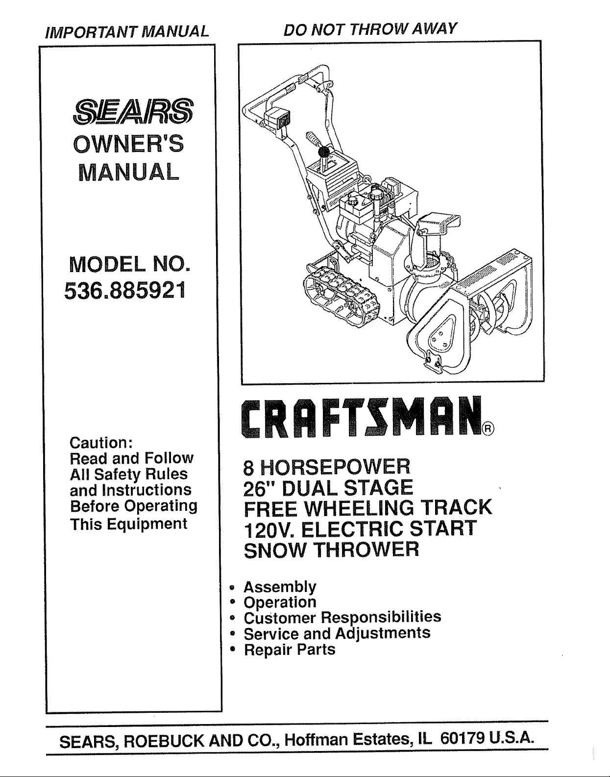
IMPORTANT MANUAL DO NOT THROW AWAY
OWNER'S
MANUAL
MODEL NO.
536.885921
Caution:
Read and Follow
All Safety Rules
and Instructions
Before Operating
This Equipment
8 HORSEPOWER
26" DUAL STAGE
FREE WHEELING TRACK
120V. ELECTRIC START
SNOW THROWER
° Assembly
• Operation
• Customer Responsibilities
° Service and Adjustments
• Repair Parts
SEARS, ROEBUCK AND CO., Hoffman Estates, IL 60179 U.S.A.
SAFETY RULES
CAUTION: ALWAYS DISCONNECT SPARK PLUG WIRE AND ._
PLACE WIRE WHERE IT CANNOT CONTACT SPARK PLUG
TO PREVENT ACCIDENTAL STARTING WHEN SETTING-UP,
TRANSPORTING, ADJUSTING OR MAKING REPAIRS,
A
IMPORTANT
SAFETY STANDARDS REQUIRE OPERATOR PRESENCE CONTROLS TO MINIMIZE THE
RISK OF INJURY, YOUR SNOW THROWER IS EQUIPPED WITH SUCH CONTROLS. DO NOT
ATTEMPT TO DEFEAT THE FUNCTION OF THE OPERATOR PRESENCE CONTROL UNDER
ANY CIRCUMSTANCES
TRAINING
1o Read the operator's manual carefully. Be
thoroughly familiar with the controls and the
proper use of the snow thrower. Know how to
stop the snow thrower and disengage the
controls quickly.
2. Never allow children tooperate the snowthrower
and keep them away while it is operating. Never
allow adults to operate the snow thrower without
proper instruction° Do not carry passengers.
3. Keep the area of operation clear of all persons,
particularly small children, and pets.
4. Exercise caution to avoid slipping or falling,
especially when operating in reverse.
PREPARATION
1. Thoroughly inspect the area where the snow
thrower is to be used and remove all doormats,
sleds, boards, wires, and other foreign objects.
2. Disengage all clutches and shift into neutral
before starting the engine (motor).
3o Do not operatethe snowthrowerwithout wearing
adequate winter outer' garments. Wear footwear
that will improve footing on slippery surfaces.
4_ Handle fuel with care; it is highly flammable_
(a) Use an approved fuel container.
(b) Never remove fuel tank cap or add fuel to a
running engine or hot engine.
(c) Fill fuel tank outdoors with extreme care.
Never fill fuel tank indoors.
(d) Replace fuel tank cap securely and wipe up
spilled fuel.
(e) Never store fuel or snow thrower with fuel in
the tank inside of abuilding where fumes may
reach an open flame or spark,
(f) Check fuel supply before each use, allowing
space for expansion as the heat of the engine
(motor) and/or sun can cause fuel to expand.
=
Use extension cords and receptacles as specified
by the manufacturer for all snow throwers with
electric drive motors or electric starting motors.
6, Adjust the snow thrower height to clear gravel or
crushed rock surfaces.
7. Never attempt to make any adjustments while the
engine (motor) is running (except when
specifically recommended by the manufacturer).
8. Let engine (motor) and snow thrower adjust to
outdoor temperatures before starting to clear
snow,
9. Always wear safety glasses or eye shields during
operation or while performing an adjustment or
repair to protect eyes from foreign objects that
may be thrown from the snow thrower.
OPERATION
1. Do not put hands or feet near or under rotating
parts. Keep clear of the discharge opening at all
times°
2, Exercise extreme caution when operating on or
crossing gravel drives, walks, or roads. Stay alert
for hidden hazards or traffic.
3_
After striking a foreign object, stop the engine
(motor), remove the wire from the spark plug,
disconnect the cord on electric motors,
thoroughly inspect the snow thrower for any
damage, and repair the damage before restarting
and operating the snow thrower_
4_
if the snow thrower should start to vibrate
abnormally, stop the (motor) and check
immediately for the cause. Vibration is generally
a warning of trouble.
5. Stop the engine (motor) whenever you leave the
operating position, before unclogging the auger!
impeller housing or discharge guide, and when
making any repairs, adjustments, or inspections.
6. When cleaning, repairing, or inspecting, make
certain the auger/impeller and all moving parts
have stopped° Disconnect the spark plug wire
and keep the wire away from the plug to prevent
accidental starting.
,
Take all possible precautions when leaving the
snow thrower unattended. Disengage the auger/
impeller, shift to neutral, stop engine, and
remove key.
2
SAFETY RULES
.
Do not run the engine indoors, except when starting
the engine and for transporting the snow thrower in
or out of the building. Open the outside doors;
exhaust fumes are dangerous (containing CARBON
MONOXIDE, an ODORLESS and DEADLY GAS).
9. Do not clear snow across the face of slopes.
Exercise caution when changing direction on
slopes. Do not attempt to clear steep slopes
10, Never operate the snow thrower without proper
guards, plates or other safety protective devices
in place.
11. Never operate the snow thrower near glass
enclosures, automobiles, window wells,
drop-offs, and the like without proper adjustment
of the snow discharge angle. Keep children and
pets away.
12. Do not overload the machine capacity by
attempting to clear snow at too fast a rate°
13. Neveroperatethe snowthrowerat high transport
speeds on slippery surfaces° Look behind and
use care when backing.
14. Never direct discharge at bystanders or allow
anyone in front of the snow thrower.
15. Disengage power to the auger/impeller when
snow thrower is transported or not in use..
167 Use only attachments and accessories approved
by the manufacturer of the snow thrower (such
as tire chains, electric start kits, etc.)
17. Never operate the snow thrower without good
visibility or light. Always be sure of your footing,
and keep a firm hold on the handles. Walk; never
run.
MAINTENANCE AND STORAGE
1. Check shear bolts and other bolts frequently for
improper tightness to be sure the snow thrower
is in safe working condition.
2. Never store the snow thrower with fuel inthe fuel
tank inside a building where ignition sources are
present such as hot water and space heaters,
clothes dryers, and the like. Allow the engine to
cool before storing in any enclosure.
3. Always refer to operator's manual instructions
for important details if the snow thrower is to be
stored for an extended period.
4. Maintain or replace safety and instruction labels,
as necessary.
5. Run the snow thrower a few minutes after
throwing snow to prevent freeze-up of the auger/
impeller.
WARNING
This snow thrower is for use on sidewalks,
driveways, and other ground level surfaces.
CAUTION should be exercised while using on
steep sloping surfaces. DO NOT USE SNOW
THROWER ON SURFACES ABOVE GROUND
LEVEL such as roofs of residences, garages,
porches or other such structures or buildings,
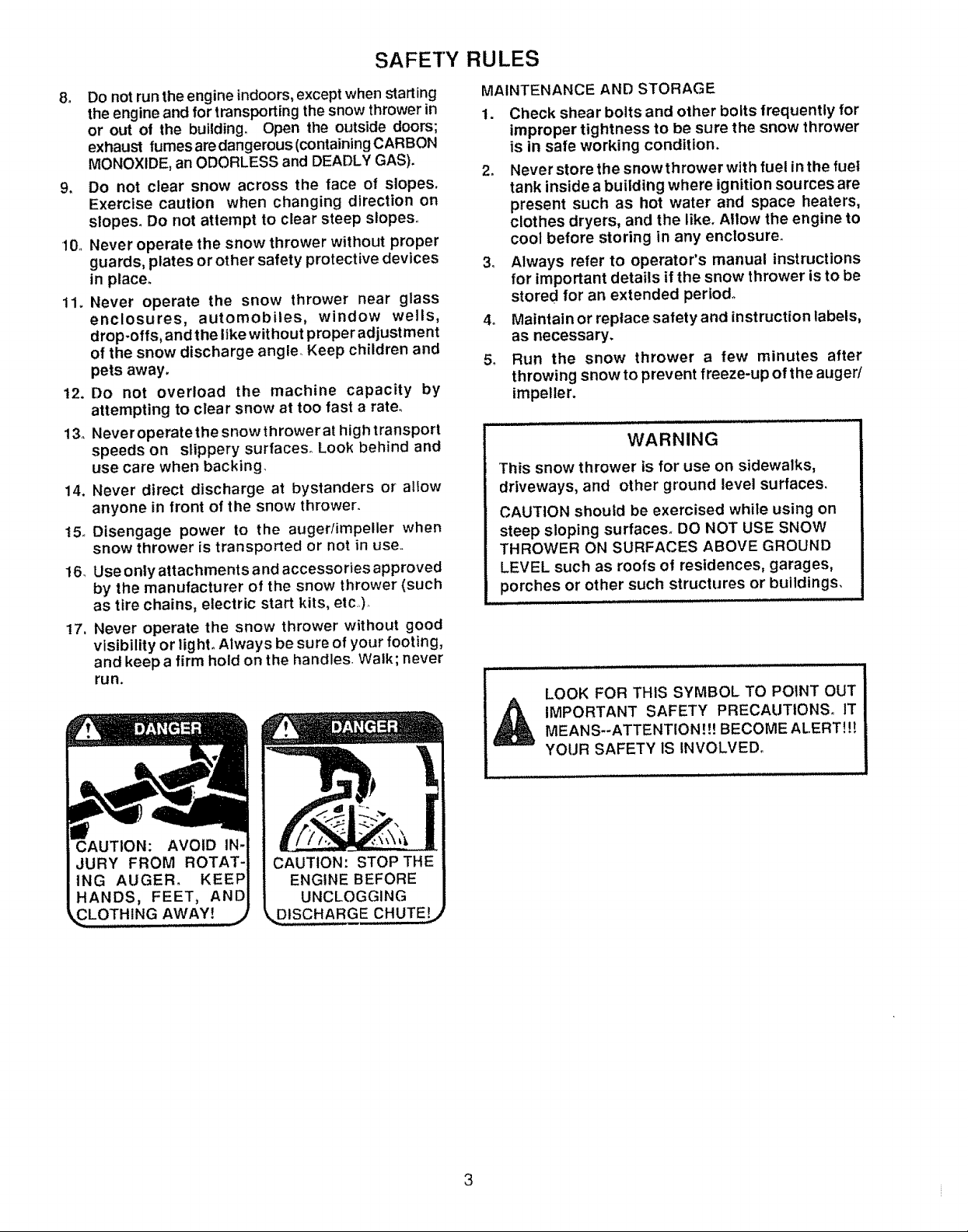
LOOK FOR THIS SYMBOL TO POINT OUT
CAUTION: AVOID IN-
JURY FROM ROTAT-
ING AUGER° KEEP
HANDS, FEET, AND
AWAY! j
_ IMPORTANT SAFETY PRECAUTIONS. ITMEANS--ATTENTION.It! BECOME ALERT!{{
YOUR SAFETY IS INVOLVED.
ENGINE BEFORE
UNCLOGGING
DISCHARGE CHUTE!
3
CONGRATULATIONS on your purchase of a Sears
Craftsman Snow Thrower.. It has been designed, engi-
neered and manufactured to give you the best possible
dependability and performance..
Should you experience any problem you cannot easily
remedy, please contact your nearest Sears Service
Center!Department, Sears has competent, well-trained
technicians and the proper tools to service or repair this
unit
Please read and retain this manual. The instructions will
enable you to assemble and maintain your snow thrower
properly. Always observe the "SAFETY RULES.."
MODEL
NUMBER 536.885921
SERIAL
NUMBER
DATE OF
PURCHASE
THE MODEL AND SERIAL NUMBERS WILL BE
FOUND ON A DECAL ATTACHED TO THE REAR
OF THE SNOW THROWER HOUSING
YOU SHOULD RECORD BOTH SERIAL NUMBER
AND DATE OF PURCHASE AND KEEP 1NASAFE
PLACE FOR FUTURE REFERENCE
, i,i
MAINTENANCE AG REEMENT
A Sears Maintenance Agreement is available on this
product Contact your nearest Sears Store for details
PRODUCT SPECIFICATIONS
HORSE POWER: 8 hp
DISPLACEMENT: 19.43
cu. in,
GASOLINE CAPACITY:
OIL (26 oz, Capacity): 5W - 30
SPARK PLUG : Champion
(GAP .030 in.) RJ19LM
VALVE CLEARANCE: intake: .010 in,
4 quarts
Unleaded
Exhaust: .010 in.
CUSTOMER RESPONSIBILITIES
e Read and observe the safety rules
e Follow a regular schedule in maintaining, caring for and using your snow thrower
® Follow the instructions under "Customer Responsibilities and "Storage" sections of this owners manual
TWO YEAR
LIMITED WARRANTY ON CRAFTSMAN
SNOW THROWER
For two years from the date of purchase, when this Craftsman Snow Thrower is maintained, lubricated
and tuned-up according to the instructions in the owner's manual, Sears witl repair, free of charge, any
defect in material and workmanship
If this Craftsman Snow Thrower is used for commercial or rental purposes, this warranty applies for only
90 days from the date of purchase.
This warranty does not cover the following:
o Expendable items which become worn during normal use, such as spark plugs, drive belts and shear
pins..
o Repairs necessary because of operator abuse or negligence, including bent crankshafts and the tailure
to maintain the equipment according to lhe instructions contained in the owner's manual
WARRANTY SERVICE IS AVAILABLE BY RETURNING THE CRAFTSMAN SNOW THROWER TO THE
NEAREST SEARS SERVICE CENTERfDEPARTMENT IN THE UNITED STATES THIS WARRANTY
APPLIES ONLY WHILE THIS PRODUCT tS IN USE IN THE UNITED STATES.
This warranty gives you specific legal rights, and you may also have other rights which may vary from
state to state.
SEARS, ROEBUCK AND CO.. Deparlrnent Dt817WA, Hoffman Estates, IL 60179
4
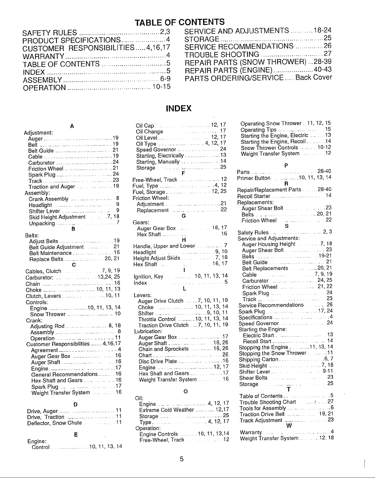
TABLE OF CONTENTS
SAFETY RULES .......................................................2,3
PRODUCT SPECIFICATIONS ..............................4
CUSTOMER RESPONSIBILITIES ..... 4,I6,17
WARRANTY .........................................................................4
TABLE OF CONTENTS ...........................................5
INDEX ...........................................................................5
ASSEMBLY .............................................................6-9
OPERATION ....................................................10-t5
SERVICE AND ADJUSTMENTS ...............18-24
STO RAGE ...................................................................25
SERVICE RECOMMENDATIONS ................ 26
TROUBLE SHOOTING .........................................27
REPAIR PARTS (SNOW THROWER) .....28-39
REPAIR PARTS (ENGINE) .........................40-43
PARTS ORDERING/SERVICE .......Back Cover
INDEX
A
Adjustment:
Auger ........................................................19
Belt ............................................................19
Belt Guide ....................................................21
Cable .........................................................19
Carburetor .................................................24
Friction Wheel ........................................21
Spark Plug .................................... 24
Track .............................................. 23
Traction and Auger ......................... 19
Assembly:
Crank Assembty .................................8
Headlight ............................................. 9
Shifter Lever ...............................................9
Skid Height Adjustment ,7, 18
Unpacking .............................. 7
B
Belts:
Adjust Belts ........................................ 19
Belt Guide Adjustment .............. 21
Belt Maintenance ............................. 16
Replace Belts ............................ 20, 21
C
Cables, Clutch ............... 7, 9, !9
Carburetor: ...................... t 3,24, 25
Chain ................................................................!6
Choke ........................................t O, 11, 13
Clutch, Levers ..................... I0, 1I
Controls:
Engine .................................!0, 11, I3, 14
Snow Thrower ......................................I0
Crank:
Adjusting Rod .....................................8, 18
Assembly ........................................ 8
Operation ................................................11
Customer Responsibilities ...........4,16,17
Agreement ............................................4
Auger Gear Box ............................... t6
Auger Shaft ................................ t 6
Engine ................................................ 17
General Recommendations ........... 16
Hex Shaft and Gears ................... 16
Spark Plug ............................ 17
Weight Transfer System ............ 16
D
Drive, Auger ...........................................11
Drive, Traction ................................... 11
Deflector, Snow Chute .......... 11
E
Engine:
Control ............................1O,1I, 13, 14
Oil Cap .............................. I2, 17
Oil Change ................ 17
Oil Level ................... 12, 17
Oil Type .....................................4, 12, 17
Speed Governor ...............................24
Starting, Electrically ...............................13
Starting, Manually ...............................14
Storage ........................................25
F
Free-Wheel, Track ......................... I2
Fuel, Type .................................. 4, t2
Fuel, Storage ...................... !2, 25
Friction Wheel:
Adjustment ............................................2t
Replacement .................................... 22
G
Gears:
Auger Gear Box ..... t 6, 17
Hex Shaft ........................ 16
H
Handle, Upper and Lower ........................7
Headlight ......................... 9, 10
Height Adjust Skids ........... 7, 18
Hex Shaft ..... 16, 17
i
Ignition, Key ............ 10, 11, 13, 14
Index ............................ 5
L
Levers:
Auger Drive Clutch ........7, I0, 11, 19
Choke ......................... 10, II, t3, t4
Shifter .................................... 9, I0, l I
Throttle Control ....................i0, ti, t3, 14
Traction Drive Clutch ..... 7, 10, 11, 19
Lubrication:
Auger Gear Box ...................................17
Auger Shaft ......................... 16, 26
Chain and Sprockets ............. 16, 26
Chart ............................................... 26
Disc Drive Plate ....................................16
Engine ...............................................12, 17
Hex Shaft and Gears ........................17
Weight Transfer System .......... 16
O
Oil:
Engine ......................................4, 12, 17
Extreme Cold Weather .................12,17
Storage ..................................... 25
Type ........................ 4, 12, 17
Operation:
Engine Controls ........... 10, I1, 13,t4
Free-Wheel, Track ............ 12
Operating Snow Thrower. tt, 12, t5
Operating Tips ............................... 15
Starting the Engine, Electric ...........13
Starting the Engine, Recoil ............ 14
Snow Thrower Controls ............. !0-12
Weight Transfer System ............ 12
P
Parts ........................................ 28-40
Primer Button ............. 10, 1I, t3, 14
R
Repair/Replacement Parts ........ 28-40
Recoil Starter ...................................... 14
Replacements:
Auger Shear Bolt ................... 23
Belts .............................. 20, 2t
Friction Wheel ...................... 22
S
Safety Rules .................................... 2, 3
Service and Adjustments:
Auger Housing Height .......... 7, t8
Auger Shear Bolt ......................... 23
Belts ...................................... 19-21
Belt Guide ...................................... 2t
Belt Replacements .......... 20, 2t
Cable ...................... 7, 9, 19
Carburetor ............................. 24, 25
Friction Wheel ............... 21,22
Spark Plug ............................. 24
Track ......................................... 23
Service Recommendations ...... 26
Spark Plug .......................... 17, 24
Specifications .............................. 4
Speed Governor .......................... 24
Starting the Engine:
Electric Start ............................. 13
Recoil Start ........................................14
Stopping the Engine .................11, t3, 14
Stopping the Snow Thrower ........... 11
Shipping Carton .......................... 6. 7
Skid Height ......................... 7, I8
Shifter Lever .................... g-t 1
Shear Bolts ............................. 23
Storage ....................... 25
T
Table of Contents ...................... 5
Troubfe Shooting Chart ................. 27
Tools for Assembly ............................. 6
Traction Drive Belt ....................... !9, 21
Track Adjustment .............................. 23
W
Warranty .................................. 4
Weight Transfer System ......... 12. t8
5
ASSEMBLY
THIS SNOW THROWER HAS A TRACK DRIVE SYSTEM EQUIPPED TO GIVE
YOU FREE WHEELING CAPABILITY.
if your snow thrower must be moved without the aid of the engine, it will be easier to pull the snow thrower back-
ward by the handles, rather than pushing For details on how to use free wheeling, see the Track Drive/Free-Wheel
Feature paragraph in the Operation section of this manual.
On start up, the track drive system may be tight and will loosen up as the snow thrower' is used. After first use,
check the track for tension and adjust if necessary. See the Track Adjustment paragraph in the Service and Adjust-
ments section of this manual Check track adjustment and fasteners regularly.
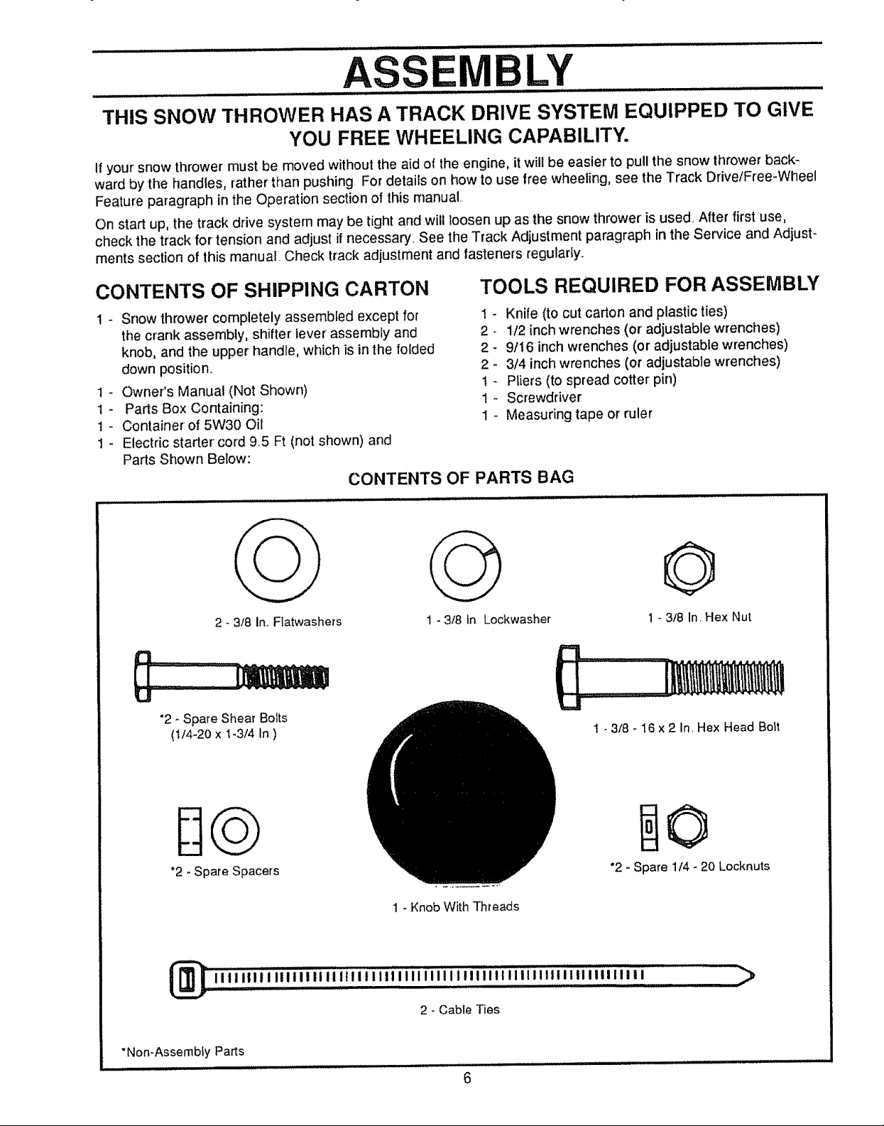
CONTENTS OF SHIPPING CARTON
! - Snow thrower completely assembled except for 1 -
the crank assembly, shifter lever assembly and 2 -
knob, and the upper handle, which is in the folded 2 -
down position. 2
1 - Owner's Manual (Not Shown) t -
1 - Parts Box Containing: 1 -
t - Container of 5W30 Oil 1 -
1 - Electric starter cord 9.5 Ft (not shown) and
Parts Shown Below:
CONTENTS OF PARTS BAG
2 - 3/8 In..Flatwashers
1 - 3/8 in Lockwasher
TOOLS REQUIRED FOR ASSEMBLY
Knife (to cut carton and plastic ties)
1/2 inch wrenches (or' adjustable wrenches)
9/t 6 inch wrenches (or adjustable wrenches)
3/4 inch wrenches (or adjustable wrenches)
Pliers (to spread cotter pin)
Screwdriver
Measuring tape or ruler
©
1- 3/8 In. Hex Nut
"2- Spare Shear Bolts
(1/4-20 x t-3/4 In.)
*2 - Spare Spacers
_iiiiillilllliilllliilliilliliiiililiiiiiiiiillllilltllilllilllil'lll ..........._
"Non-Assemb{y Parts
i t i i iiu lll_ li,Hi, i i i lll i,i/ii, i,u,i.i H,i ,,it ,i i_tlll,l.,
! - 3t8 - 16 x 2 In, Hex Head Bolt
*2 - Spare 1/4 - 20 Locknuts
1 - Knob With Threads
2 - Cabte Ties
6
........................................................................ASSE....LY .......................
Figure 1 shows the snow thrower in the shipping position,
Figure 2 shows the snow thrower completely assembled,
Reference to the right and left hand side of the snow thrower
is from the operator's position at the handle,
TO REMOVE SNOW THROWER
FROM CARTON (See Fig. 1)
e Remove the staples from top of carton to avoid injury
e Remove top pallet from carton.
• Locate and remove container of 5W30 oil in parts box,
e Cut and discard plastic ties securing the crank assem.
bly to the pallet and place the assembly aside. Discard
pallet,
e Cut all fourcorners of the carton from top to bottom and
lay the panels flat,
• Cut the bands holding the snow thrower to the tower
pallet..
e Remove packing from console
• Remove paper ties from upper handles,
e With two 9/!6 inch wrenches, _oosen (but do not
remove) both bolts securing the upper and lower
handles by holding the inner nut on the inside of the
handle wh}le turning the outside bolt counter-clock-
wise as shown in Fig 4A, page 8
e Swing the upper handle into the operating position as
shown in Fig, 2,
e Hold the inner nut and tighten the outside bolt up
against the handle as shown in Fig 4A, page 8
LowEnHANI LE..........
FIG. 1
AUGERD,iV .........
CLUTCH
HEADLIGHT SHIFTER
DRIVE
LEVER
LEVER
PANEL
CLUTCH
CABLE
UPPER
HANDLE
ASSEMBLY
CHUTE
e Position control panel bracket so that the slot is in tine
with mounting hole in the panet.
e While holding the outside bo_t, tighten the innermost
nut up against the control panel bracket as shown in
Fig. 4A, page 8,
NOTE: If the cables have become disconnected from the
clutch levers, reinstall thecables asshown in Fig 3 and Fig
3A,,
o
Tighten handle bolts securely
O
Rol! the snow thrower off the skid by pulling on the
handle, CAUTION; DO NOT back over cables
e Properly dispose of discarded packing.
NOTE: This snow thrower is equipped with a track drive and
can be hard to push when the engine is not running,
However, this unit has kfick pins in the track wheels which,
in the proper setting, allow the unit to be transported easily
without the engine being started, For instructions on the use
of these klick pins. see the Track Drive/Free-Wheel Feature
on page I2,
4" LG, FREE 3" LG, FREE
TRACTION _STATE
DRIVE"-... /
SPR,.G
TRAOT,O.
DRWE II ///,_71_,
SPRING ---_
LEVEF_ _ .
FIG. 3A
FIG. 2
FIG, 3
CAUTION: IF YOU ARE REMOVING
A SNOW FROM ANY GRAVELED OR UN-
SKIDS DOWN. THIS WiLL HELP TO PREVENT
STONES AND OTHER DEBRIS FROM BEING
PICKED UP AND THROWN BY THE AUGER.
EVEN SURFACE, RAISE THE FRONT OF
THE SNOWTHROWER BY MOVING THE
, N
DRIVE
LEVER
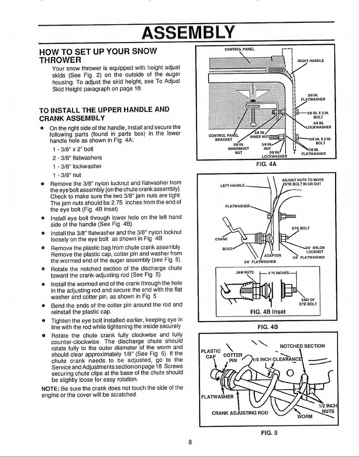
HOW TO SET UP YOUR SNOW
THROWER
Your snow thrower is equipped with height adjust
skids (See Fig. 2) on the outside of the auger
housing. To adjust the skid height, see To Adjust
Skid Height paragraph on page 18,.
TO INSTALL THE UPPER HANDLE AND
CRANK ASSEMBLY
On the right side of the handle, installand secure the
following parts (found in parts box) in the lower
handle hole as shown in Fig 4A:
1 - 3/8" x 2" bolt
2 - 3/8" flatwashers
t - 3/8" lockwasher
t - 3/8" nut
® Remove the 318" nylon locknut and flatwasher from
the eye bolt assembly (on the chute crank assembly).
Check to make sure the two 3/8" jam nuts are tight,
The jam nuts should be 275 inches from the end of
the eye bolt (Fig. 4B inset)
e Install eye bolt through lower hole on the left hand
side of the handle (See Fig. 4B).
• Install the 3/8" flatwasher and the 3/8" nylon locknut
loosely on the eye bolt as shown in Fig 4B
e Remove the plastic bag from chute crank assembly
Remove the plastic cap, cotter pin and washer from
the wormed end of the auger assembly (see Fig 5),
® Rotate the notched section of the discharge chute
toward the crank-adjusting rod (See Fig 5).
e install the wormed end of the crank fhrough the hole
in the adjusting rod and secure the end with the flat
washer and cotter pin, as shown in Fig 5
• Bend the ends of the cotter pin around the rod and
reinstall the plastic cap,,
e Tighten the eye bolt installed earlier, keeping eye in
line with the rod while tightening the inside securely
• Rotate the chute crank fully clockwise and fully
counter-clockwise. The discharge chute should
rotate fully to the outer diameter of the worm and
should clear approximately 1/8" (See Fig. 5).. If the
chute crank needs to be adjusted, go to the
Service and Adjustments section on page 18 Screws
securing chute clips at the base of the chute should
be slightly loose for easy rotation,.
NOTE: Be sure the crank does not touch the side of the
engine or the cover will be scratched,
BRACKET
3mlN, BOLT
INNERMOST NUT
NUT 3,"8 FLAT'WASHER
LOCKWASHER
FIG. 4A
CRANK
3/8 _ FLA"P#ASHER
JAM NUTS
2.75 IN_
FIG. 4B inset
i[ iL ,,,,,,,,,,,
FIG. 4B
PLASTIC % ,.
"_" NOTCHED SECTION
CAP COTTER
PIN /8 INCHCLEABANC
FLA
ADJUST NUTS TO MOVE
EYE :BOLT IN OR OUT
EYE BOLT
NYLON
3_/8 LOCKNUT
FLATWASHER
I END OF
EYE BOLT
O
| _ _k\,, J//_".,,_ 1/2 INCH
FIG, 5
8
ASSEM LY
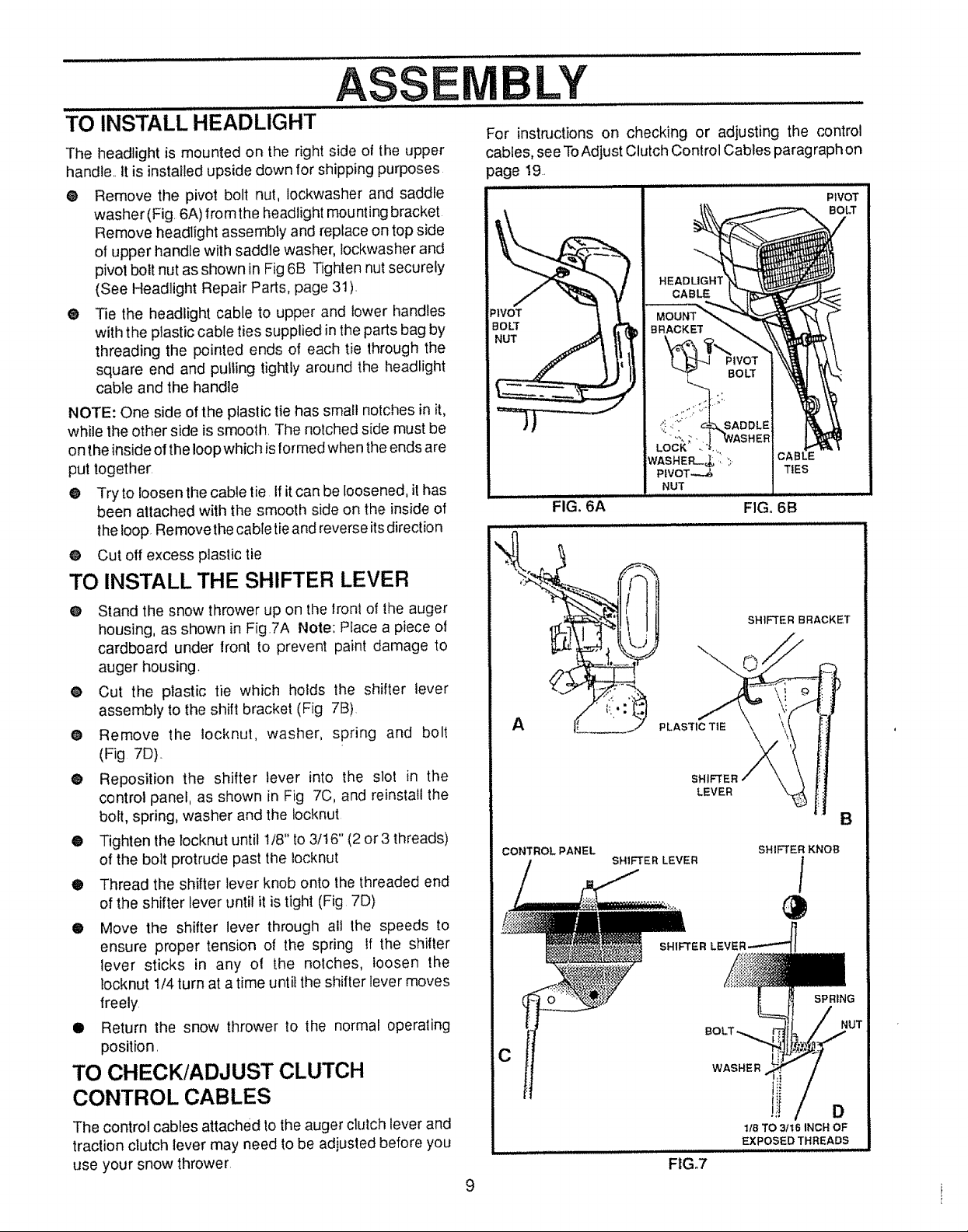
TO INSTALL HEADLIGHT
The headlight is mounted on the right side of the upper
handle., it is installed upside down for shipping purposes
® Remove the pivot bolt nut, lockwasher and saddle
washer (Fig. 6A) from the headlight mounting bracket
Remove headlight assembly and replace on top side
of upper handle with saddJe washer, Jockwasher and
pivot bolt nut as shown in Fig6B Tighten nut securely
(See Headlight Repair Parts, page 31).
® Tie the headlight cable to upper and lower handles
with the plastic cable ties supplied in the parts bag by
threading the pointed ends of each tie through the
square end and putling tightly around the headlight
cable and the handle
NOTE: One side of the plastic tie has small notches in it,
while the other side is smooth. The notched side must be
on the inside o! the loop which is formed when the ends are
put together:
@ Try to loosen the cable tie If it can be loosened, it has
been attached with the smooth side on the inside of
the loop. Removethe cable tieand reverse its direction
@ Cut off excess plastic tie
TO INSTALL THE SHIFTER LEVER
For instructions on checking or adjusting the control
cables, see To Adjust Clutch Control Cables paragraph on
page 19.
PIVOT
_'IVOT
BOLT
NUT
BOLT
TIES
FIG_ 6A FIG. 6B
O Stand the snow thrower up on the lronl of the auger
housing, as shown in Fig.7A Note: Place a piece of
cardboard under front to prevent paint damage to
auger housing.
• Cut the plastic tie which holds the shifter lever
assembly to the shift bracket (Fig 7B)
• Remove the iocknut, washer, spring and bolt
(Fig 7D)..
@ Reposition the shifter lever into the slot in the
control panel, as shown in Fig 7C, and reinstall the
bolt, spring, washer and the Iocknut
• Tighten the locknut until 1/8" to 3/t6" (2 or3 threads)
of the bolt protrude past the locknut
® Thread the shifter lever knob onto the threaded end
of the shifter lever until it is tight (Fig 7D)
• Move the shifter lever through all the speeds to
ensure proper tension of the spring If the shifter
lever sticks in any ol the notches, loosen the
locknut 1/4 turn at a time until the shifter lever moves
freely
• Return the snow thrower to the normal operating
position.
TO CHECK/ADJUST CLUTCH
CONTROL CABLES
The control cables attached to the auger clutch lever and
traction clutch fever may need to be adjusted before you
use your snow thrower
9
CONTROLPANEL
C
SHIFTER LEVER
SHIFTER
FtG.7
SHIFTER
LEVER
SHIFTER KNOB
/
SPRING
WASHER
D
lib TO _t6 INCH OF
EXPOSEDTHREADS
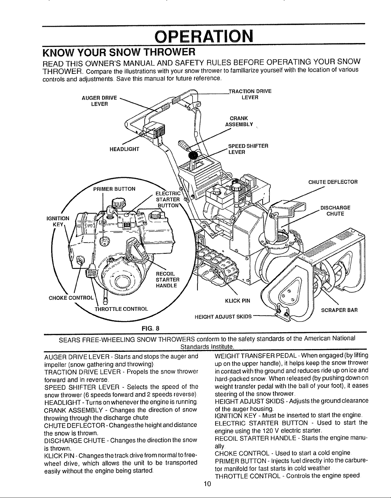
OPERATION
KNOW YOUR SNOW THROWER
READ THIS OWNER'S MANUAL AND SAFETY RULES BEFORE OPERATING YOUR SNOW
THROWER° Compare the illustrations with your snow thrower to familiarize yourself with the location of various
controls and adjustments, Save this manual for' future reference,,
,TRACTION DRIVE
AUGER DRIVE
LEVER
LEVER
CRANK
ASSEMBLY
m
IGNITION
KEY
CHOKECONTROL
HEADLIGHT
THROTTLE CONTROL
TARTER
RECOIL
STARTER
HANDLE
SPEED SHIFTER
CHUTE DEFLECTOR
DISCHARGE
CHUTE
KLICK PIN
SCRAPER BAR
HEIGHT ADJUST SKIDS
FIG. 8
SEARS FREE-WHEELING SNOW THROWERS conform to the safety standards of the American National
Standards Institute.
AUGER DRIVE LEVER - Starts and stops the auger and
impeller (snow gathering and throwing)
TRACTION DRIVE LEVER - Propels the snow thrower
forward and in reverse,
SPEED SHIFTER LEVER - Selects the speed of the
snow thrower (6 speeds forward and 2 speeds reverse)
HEADLIGHT - Turns on whenever the engine is running
CRANK ASSEMBLY - Changes the direction of snow
throwing through the discharge chute,
CHUTE DEFLECTOR -Changes the height and distance
the snow is thrown.
DISCHARGE CHUTE - Changes the direction the snow
is thrown.
KLICK PIN - Changes the track drive from normal to free-
wheel drive, which allows the unit to be transported
easily without the engine being started.
WEIGHT TRANSFER PEDAL- When engaged (by lifting
up on the upper handle), it hefps keep the snow thrower
in contact with the ground and reduces ride up on ice and
hard-packed snow When released (by pushing down on
weight transfer pedal with the ball of your foot), it eases
steering of the snow thrower.
HEIGHT ADJUST SKIDS -Adjusts the ground clearance
of the auger housing
IGNITION KEY - Must be inserted to start the engine
ELECTRIC STARTER BUTTON - Used to start the
engine using the 120 V electric starter,.
RECOIL STARTER HANDLE _Starts the engine manu_.
ally.
CHOKE CONTROL - Used to start a cold engine
PRIMER BUTTON - Injects fuel directly into the carbure-
tor manifold for fast starts in cold weather
THROTTLE CONTROL - ControLs the engine speed
10
The operation of any snow thrower can result in foreign objects being thrown into the
eyes, which can result in severe eye damage Always wear safety glasses or eye
shields while operating the snow thrower.
We recommend standard safety glasses or wide vision safety mask for over your
glasses avaRable at SEARS Retail or Catalog Stores..
iii.i....... i i i i i,,i :: iJ .......... ................ :
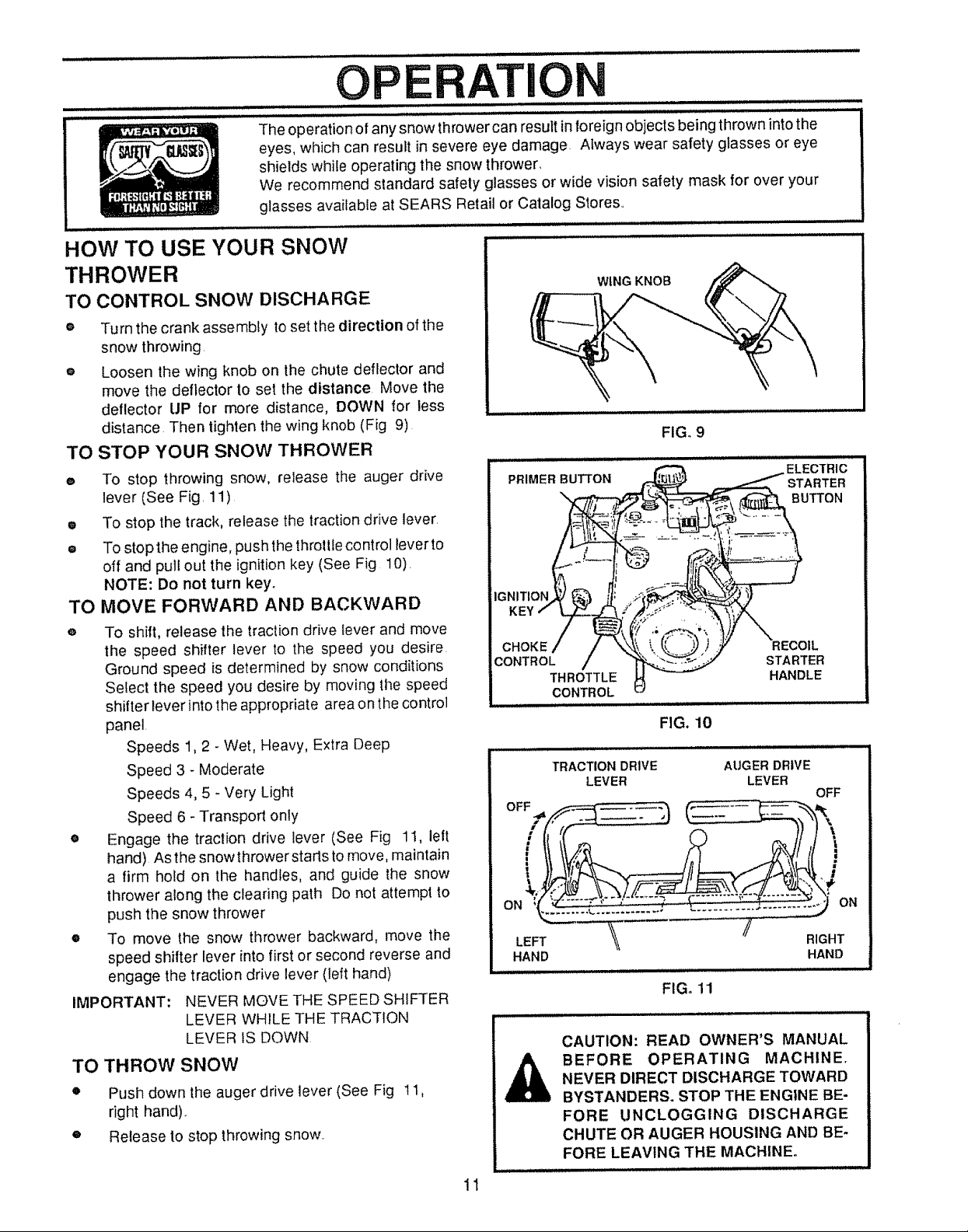
HOW TO USE YOUR SNOW
THROWER
TO CONTROL SNOW DISCHARGE
o Turn the crank assembly to set the direction of the
snow throwing.
e Loosen the wing knob on the chute deflector and
move the deflector to set the distance Move the
deflector UP for more distance, DOWN for less
distance Then tighten the wing knob (Fig 9)
TO STOP YOUR SNOW THROWER
e To stop throwing snow, release the auger drive
lever (See Fig. 11)
• To stop the track, release the traction drive lever.
= To stop the engine, pushthe throttlecontrol lever to
off and pull out the ignition key (See Fig 10).
NOTE: Do not turn key.
TO MOVE FORWARD AND BACKWARD
To shift, release the traction drive tever and move
the speed shifter lever to the speed you desire.
Ground speed is determined by snow conditions
Select the speed you desire by moving the speed
shifter lever into the appropriate area on the control
panel.
Speeds 1,2 - Wet, Heavy, Extra Deep
Speed 3 - Moderate
Speeds 4, 5 - Very Light
Speed 6 - Transport only
Engage the traction drive lever (See Fig 1I, left
hand) Asthe snowthrowerstarts to move, maintain
a firm hold on the handles, and guide the snow
thrower along the clearing path Do not attempt to
push the snow thrower
To move the snow thrower backward, move the
speed shifter lever into first or second reverse and
engage the traction drive lever (left hand)
iMPORTANT:
NEVER MOVE THE SPEED SHIFTER
LEVER WHILE THE TRACTION
LEVER fS DOWN
TO THROW SNOW
o
Push down the auger drive lever (See Fig 1t,
right hand)..
o
Release to stop throwing snow..
CHOKE
CONTROL
HAND
A
WING KNOB
FIGo9
THROTTLE
CONTROL
STARTER
HANDLE
FIG. 10
Hi i =
TRACTION DRIVE
LEVER
ii i,, .................
AUGER DRIVE
LEVER
RIGHT
HAND
FIG. 11
CAUTION: READ OWNER'S MANUAL
BEFORE OPERATING MACHINE.
NEVER DIRECT DISCHARGE TOWARD
BYSTANDERS. STOP THE ENGINE BE-
FORE UNCLOGGING DISCHARGE
CHUTE OR AUGER HOUSING AND BE-
FORE LEAVING THE MACHINE_
OFF
1t
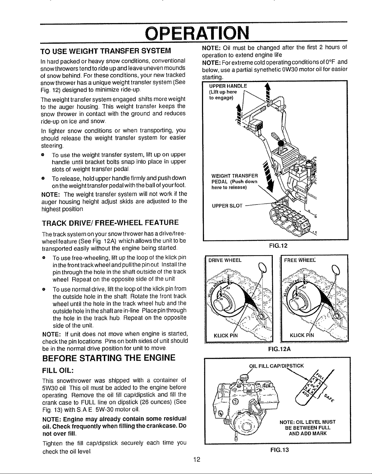
OPERAI=ION
TO USE WEIGHT TRANSFER SYSTEM
In hard packed or heavy snow conditions, conventional
snow throwers tend to ride up and leave uneven mounds
of snow behind. For these conditions, your new tracked
snow thrower has a unique weight transfer system (See
Fig,,12) designed to minimize dde-up,.
The weight transfer system engaged shifts more weight
to the auger housing. This weight transfer keeps the
snow thrower in contact with the ground and reduces
ride-up on ice and snow..
In lighter' snow conditions or when transporting, you
should release the weight transfer system for easier
steering.
® To use the weight transfer system, lift up on upper
handle until bracket bolts snap into place in upper
slots of weight transfer pedal.
e To release, hold upper handle firmly and push down
on the weight transfer pedal with the ball of your fool
NOTE: The weight transfer system will not work if the
auger housing height adjust skids are adjusted to the
highest position
NOTE: Oil must be changed after the first 2 hours of
operation to extend engine life
NOTE: For extreme cold operating conditions of 0°F and
below, use a partial synethetic 0W30 motor oil for' easier
starting. ........................
UPPER HANDLE
(Lift up here
to engage)
WEIGHT TRANSFER
PEDAL (Push down
here to release)
UPPER SLOT
TRACK DRIVE/FREE-WHEEL FEATURE
The track system on your snow thrower has adrive/free_
wheel feature (See Fig, 12A) which allows the unit to be
transported easily without the engine being started..
® To use free-wheeling, lift up the loop of the kfick pin
in the front track wheel and pull the pin out Install the
pin through the hole in the shaft outside of the track
wheel Repeat on the opposite side of the unit
o To use normal drive, lift the loop of the klick pin from
the outside hole in the shaft.. Rotate the front track
wheel until the hole in the track wheel hub and the
outside hole in the shaft are in-line Place pin through
the hole in the track hub. Repeat on the opposite
side of the unit,.
NOTE: If unit does not move when engine is started,
check the pin locations, Pins on both sides of unit should
be in the normal drive position for unit to move,
BEFORE STARTING THE ENGINE
FILL OIL:
This snowthrower was shipped with a container of
5W30 oi!. This oil must be added to the engine before
operating Remove the oil fii! cap/dipstick and fill the
crank case to FULL line on dipstick (26 ounces) (See
Fig, 13) with SAE 5W-30 motor oil
NOTE: Engine may already contain some residual
oil. Check frequently when filling the crankcase. Do
not over fill.
Tighten the fill cap/dipstick securely each time you
check the oil level,
12
DRIVE WHEEL
FIG. 12
FREEWREEt_
KUCK PIN
FIG.12A
OIL FILL CAPtDIPSTICK
%
NOTE: OIL LEVEL MUST
BE BETWEEN FULL
AND ADD MARK
FIGo13
OPE ATIO
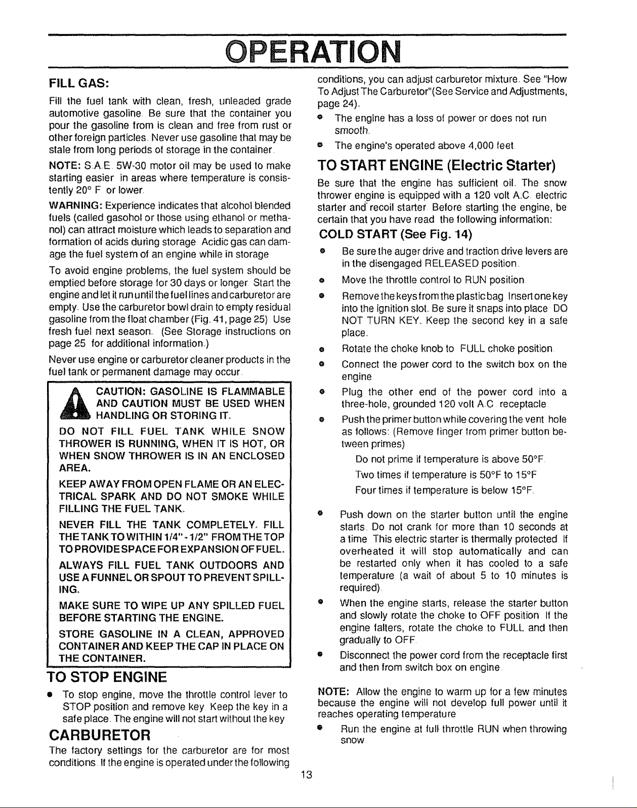
FILL GAS:
Fill the fuel tank with clean, fresh, unleaded grade
automotive gasoline. Be sure that the container you
pour the gasoline from is clean and free from rust or
other foreign particles. Never use gasoline that may be
stale from long periods of storage in the container.
NOTE: SAE. 5W-30 motor oil may be used to make
starting easier in areas where temperature is consis-
tentty 20° F or lower.
WARNING: Experience indicates that alcohol blended
fuels (called gasohol or those using ethanol or metha-
nol) can attract moisture which leads to separation and
formation of acids during storage Acidic gas can dam-
age the fuel system of an engine while in storage
To avoid engine problems, the fuel system should be
emptied before storage for 30 days or longer Start the
engine and let it run untilt he fuel lines and carbureto rare
empty. Use the carburetor bowl drain to empty residual
gasoline from the float chamber (Fig. 41, page 25) Use
fresh fuel next season. (See Storage instruclions on
page 25 for additional information)
Never use engine or carburetor cleaner products in the
fuel tank or permanent damage may occur.
_ AUTION: GASOLINE IS FLAMMABLE
DO NOT FILL FUEL TANK WHILE SNOW
THROWER IS RUNNING, WHEN 1T IS HOT, OR
WHEN SNOW THROWER IS IN AN ENCLOSED
AREA.
KEEP AWAY FROM OPEN FLAME OR AN ELEC-
TRICAl. SPARK AND DO NOT SMOKE WHILE
FILLING THE FUEL TANK,.
NEVER FILL THE TANK COMPLETELY. FILL
THE TANKTOWlTHIN 1/4".- t12" FROMTHETOP
TO PROVIDE SPACE FO R EXPANSION OF FUEL.
ALWAYS FILL FUEL TANK OUTDOORS AND
USE A FUNNEL OR SPOUT TO PREVENT SPILL-
INGo
MAKE SURE TO WIPE UP ANY SPILLED FUEL
BEFORE STARTING THE ENGINE.
STORE GASOLINE IN A CLEAN, APPROVED
CONTAINER AND KEEP THE CAP IN PLACE ON
THE CONTAINER.
AND CAUTION MUST BE USED WHEN
HANDLING OR STORING IT,,
TO........STOP ENGINE .......................................
• To stop engine, move the throttle control lever to
STOP position and remove key Keep the key in a
safe place. The engine will not start without the key
CARBURETOR
The factory settings for the carburetor are for most
conditions. If the engine is operated under the following
13
conditions, you can adjust carburetor mixture See "How
To Adjust The Carburetor"(See Service and Adjustments,
page 24)_,
® The engine has a loss o{ power or does not run
smooth.
® The engine's operated above 4,000 feet
TO START ENGINE (Electric Starter)
Be sure that the engine has sufficient oil The snow
thrower engine is equipped with a 120 volt A.C electric
starter and" recoil starter Before starting the engine, be
certain that you have read the following information:
COLD START (See Fig. 14)
o Be sure the auger drive and traction drive levers are
in the disengaged RELEASED position.
o Move the throttle control to RUN position
® Removethe keys fromthe plastic bag Insert one key
intothe ignition slot,. Be sure it snaps into place DO
NOT TURN KEY,. Keep the second key in a safe
place..
e Rotate the choke knob to FULL choke position
o Connect the power cord to the switch box on the
engine
o Plug the other end of the power cord into a
three-hole, grounded 120 volt A.C receptacle
o Push the primer button while covering the vent hole
as follows: (Remove finger from primer button be-
tween primes)
Do not prime il temperature is above 50°F
Two times if temperature is 50°F to 15°F
Four times if temperature is below 15°F.
o Push down on the starter button until the engine
starts. Do not crank for more than 10 seconds at
a time This electric starter is thermally protected If
overheated it will stop automatically and can
be restarted only when it has cooled to a safe
temperature (a wait of aboul 5 to 10 minutes is
required).
® When the engine starts, release the starter button
and slowly rotate the choke to OFF position If the
engine falters, rotate the choke to FULL and then
gradually to OFF.
e Disconnect the power cord from the receptacle lirst
and then from switch box on engine
NOTE: Allow the engine to warm up for a few minutes
because the engine will not develop full power until it
reaches operating temperature
• Run the engine at lull throttle RUN when throwing
snow
TI
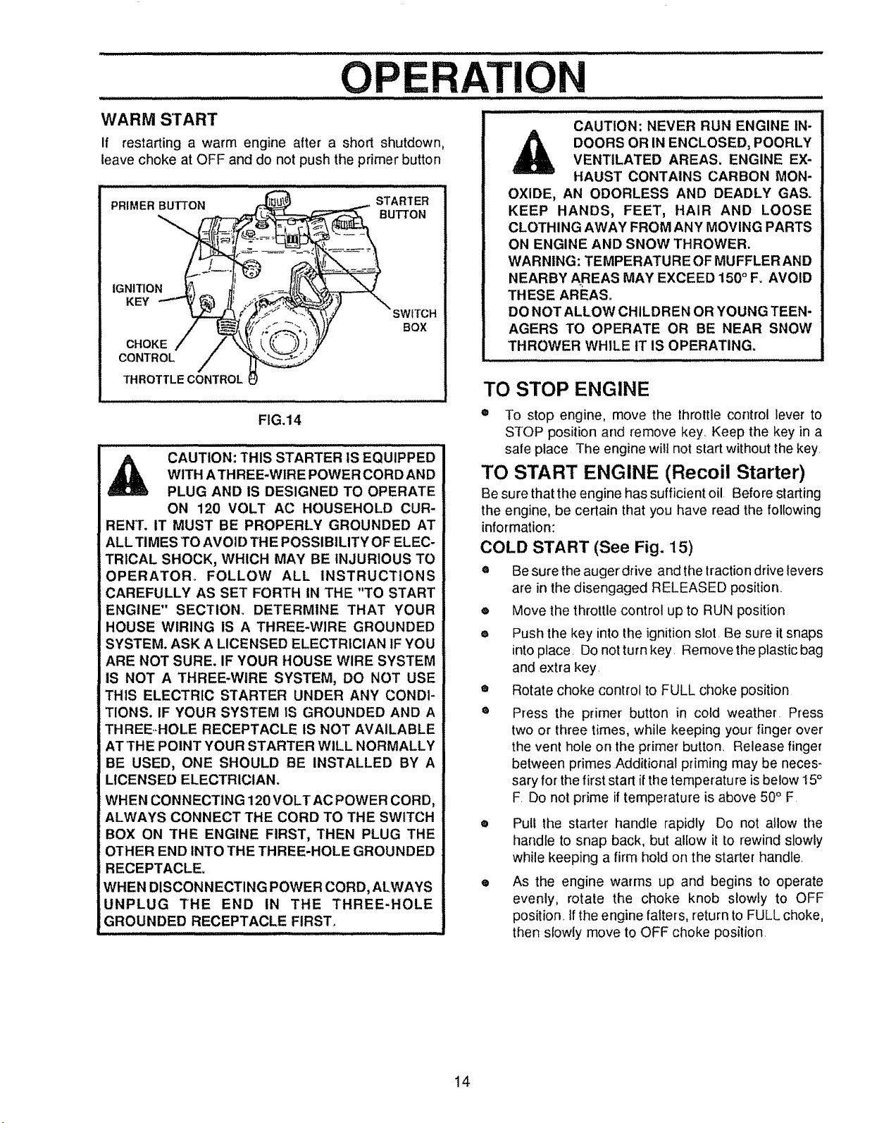
WARM S'rART
If restarting a warm engine after a short shutdown,
leave choke at OFF and do not push the primer button
FIG.14
CAUT,0NiTH,SSTARTER,SEaU,PPE0
W,THATHREE-WIREPOWERCORDAND
PLUG AND iS DESIGNED TO OPERATE
ON 120 VOLT AC HOUSEHOLD CUR-
BEN'[. IT MUST BE PROPERLY GROUNDED AT
ALL TIMES TO AVOID THE POSSIBILITY OF ELEC-
TRICAL SHOCK, WHICH MAY BE INJURIOUS TO
OPERATOR_ FOLLOW ALL INSTRUCTIONS
CAREFULLY AS SET FORTH IN THE "TO START
ENGINE" SECTION. DETERMINE THAT YOUR
HOUSE WIRING IS A THREE*WIRE GROUNDED
SYSTEM. ASK A LICENSED ELECTRICIAN tF YOU
ARE NOT SURE. IF YOUR HOUSE WIRE SYSTEM
IS NOT A THREE-WIRE SYSTEM, DO NOT USE
THIS ELECTRIC STARTER UNDER ANY CONDI-
TIONS. IF YOUR SYSTEM IS GROUNDED AND A
THREEHOLE RECEPTACLE iS NOT AVAILABLE
AT THE POINT YOUR STARTER WILL NORMALLY
BE USED, ONE SHOULD BE INSTALLED BY A
LICENSED ELECTRICIAN.
WHEN CONNECTING 120 VOLT AC POWER CORD,
ALWAYS CONNECT THE CORD TO THE SWITCH
BOX ON THE ENGINE FIRST, THEN PLUG THE
OTHER END iNl"O THE THREE-HOLE GROUNDED
RECEPTACLE.
WHEN DISCONNECTING POWER CORD, ALWAYS
UNPLUG THE END IN THE THREE-HOLE
GROUNDED RECEPTACLE FIRST.
CAUTION: NEVER RUN ENGINE IN-
DOORS OR IN ENCLOSED, POORLY
VENTILATED AREAS. ENGINE EX-
HAUST CONTAINS CARBON MON-
OXIDE, AN ODORLESS AND DEADLY GAS_
KEEP HANDS, FEET, HAIR AND LOOSE
CLOTHING AWAY FROM ANY MOVING PARTS
ON ENGINE AND SNOW THROWER.
WARNING: TEMPERATURE OF MUFFLERAND
NEARBY AREAS MAY EXCEED 150° F. AVOID
THESE AREAS.
DO NOT ALLOW CHILDREN OR YOUNG TEEN-
AGERS TO OPERATE OR BE NEAR SNOW
THROWER WHILE IT IS OPERATING.
TO STOP ENGINE
® To stop engine, move the throttle control lever to
STOP position and remove key Keep the key in a
safe peace The engine will not start without the key
TO START ENGINE (Recoil Starter)
Be sure that the engine has sufficient oil Before starting
the engine, be certain that you have read the following
information:
COLD START (See Fig. 15)
e Be sure the auger drive and the lractiondrive levers
are in the disengaged RELEASED position
,=, Move the throttle control up to RUN position
e Push the key into the ignitionslot Be sure it snaps
into place Do not turn key Remove the plastic bag
and extra key
• Rotate choke control to FULL choke position
® Press the primer button in cold weather Press
two or three times, while keeping your finger over
the vent hole on the primer button. Release finger
between primes Additional priming may be neces-
sary for the first start if the temperature is below 15°
F Do not prime if temperature is above 50° F
• Pull the starter handie rapidly Do not allow the
handle to snap back, but allow it to rewind slowly
while keeping a firm hold on the starter handle
e As the engine warms up and begins to operate
evenly, rotate the choke knob slowly to OFF
position _tf the engine falters, return to FULL choke,
then slowly move to OFF choke position
14
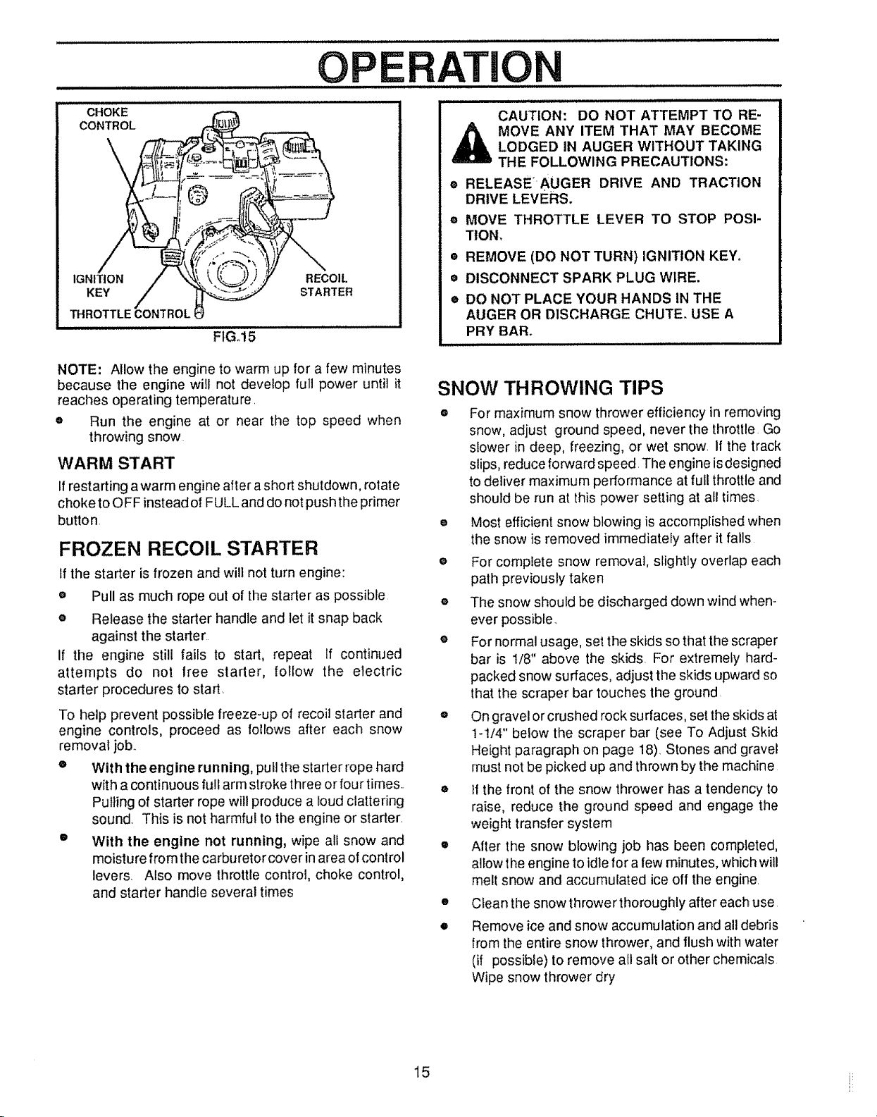
O E
TION
CHOKE
CONTROL
IGNITION RECOIL
KEY STARTER
THROTTLECONTROLI
FIG°15
NOTE: Allow the engine to warm up for a few minutes
because the engine will not develop full power until it
reaches operating temperature.
o
Run the engine at or near the top speed when
throwing snow
WARM START
If restarting awarm engine after a short shutdown, rotate
choke to OFF instead of FULL and do not push the primer
button,
FROZEN RECOIL STARTER
If the starter is frozen and will not turn engine:
• Pull as much rope out of the starter as possible
e Release the starter handle and let it snap back
against the starter
If the engine still fails to start, repeat If continued
attempts do not free starter, follow the electric
starter procedures to start.
To help prevent possible freeze-up of recoil starter and
engine controls, proceed as follows after each snow
removal job..
e With the engine running, pull the starter rope hard
with a continuous full arm stroke three or four times.
Pulling of starter rope will produce a loud clattering
sound Th{s is not harmful to the engine or starter_
e With the engine not running, wipe ali snow and
moisture from the carburetor cover in area of control
levers. Also move throttle control, choke control,
and starter handle several times
CAUTION: DO NOT ATTEMPT TO RE-
MOVE ANY ITEM THAT MAY BECOME
LODGED IN AUGER WITHOUT TAKING
THE FOLLOWING PRECAUTIONS:
e RELEASE'_AUGER DRIVE AND TRACTION
DRIVE LEVERS,
® MOVE THROTTLE LEVER TO STOP POSI-
TION,
• REMOVE (DO NOT TURN) IGNITION KEY.
• DISCONNECT SPARK PLUG WIRE.
® DO NOT PLACE YOUR HANDS IN THE
AUGER OR DISCHARGE CHUTE. USE A
PRY BAR.
SNOW THROWING TIPS
® For maximum snow thrower efficiency in removing
snow, adjust ground speed, never the throttle Go
slower in deep, freezing, or wet snow. If the track
slips, reduce forward speed. The engine is designed
to deliver maximum performance at full throttle and
should be run at this power setting at all times.
o Most efficient snow blowing is accomplished when
the snow is removed immediately after it falls
e For complete snow removal, slightly overlap each
path previously taken
o The snow should be discharged down wind when-
ever possible.
e For normal usage, set the skids so that the scraper
bar is 1/8" above the skids For extremely hard-
packed snow surfaces, adjust the skids upward so
that the scraper bar touches the ground
o On gravel or crushed rock sutraces, set the skids at
t-!/4" below the scraper bar (see To Adjust Skid
Height paragraph on page 18) Stones and gravel
must not be picked up and thrown by the machine
e If the front of the snow thrower has a tendency to
raise, reduce the ground speed and engage the
weight transfer system
o After the snow blowing job has been completed,
allow the engine to idle for a few minutes, which will
melt snow and accumulated ice off the engine.
• Clean the snow thrower thoroughly after each use
• Remove ice and snow accumulation and all debris
from the entire snow thrower, and flush with water
(if possible) to remove all salt or other chemicals
Wipe snow thrower dry
15 i_
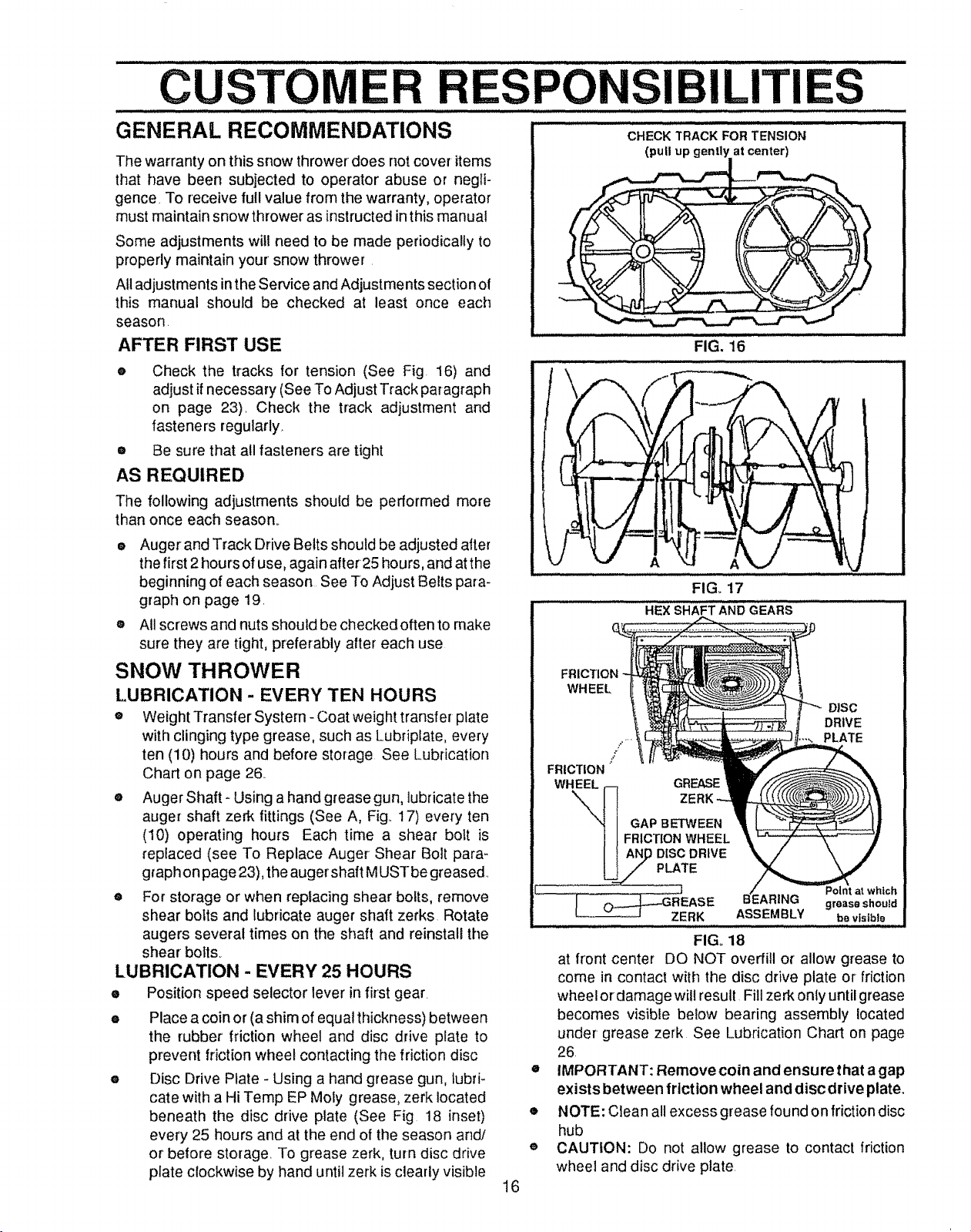
CUSTOMER RESPONSIBILITIES
GENERAL RECOMMENDATIONS ..................
CHECK TRACK FOR TENSION
The warranty on this snow thrower does not cover items
that have been subjected to operator abuse or negli-
gence, To receive full value from the warranty, operator
must maintain snow thrower as instructed in this manual
Some adjustments will need to be made periodically to
properly maintain your snow thrower.
All adjustments in the Service and Adjustments section of
this manual should be checked at least once each
season.
AFTER FIRST USE
e Check the tracks for tension (See Fig. 16) and
H ii
adjust if necessary (See To Adjust Track paragraph
on page 23). Check the track adjustment and
fasteners regularly.
® Be sure that all fasteners are tight
,i,, i iii ,Ll,,i llllll ,, ,_,,,_,, ,_,,
AS REQUIRED
The following adjustments should be performed more
than once each season.
J/
e Augerand Track Drive Belts should be adjusted after
the first 2 hours of use, again after25 hours, and atthe
beginning of each season See To Adjust Belts para-
graph on page 19.
® All screws and nuts should be checked often to make
sure they are tight, preferably after each use
SNOW THROWER
LUBRICATION - EVERY TEN HOURS
® Weight Transfer System- Coat weight transfer plate
with clinging type grease, such as Lubriplate, every
ten (10) hours and before storage See Lubrication
Chart on page 26
• Auger Shaft- Using a hand grease gun, lubricate the
auger shaft zerk fittings (See A, Fig.. 17) every ten
(10) operating hours Each time a shear bolt is
replaced (see To Replace Auger Shear Bolt para-
graph on page 23), the auger shaft MUST be greased..
® For storage or when replacing shear bolts, remove
shear bolts and lubricate auger shaft zerks Rotate
augers several times on the shaft and reinstall the
shear bolts_
LUBRICATION - EVERY 25 HOURS
e Position speed selector lever in first gear.
e Place a coin or (a shim of equal thickness) between
the rubber friction wheel and disc drive plate to
prevent friction wheel contacting the friction disc
e Disc Drive Plate - Using a hand grease gun, lubri-
cate with a Hi Temp EP Moly grease, zerk located
beneath the disc drive plate (See Fig 18 inset)
every 25 hours and at the end of the season and/
or before storage. To grease zerk, turn disc drive
plate clockwise by hand until zerk is clearly visible
16
WHEEL
FRICTION
WHEEL
!
GAP BETWEEN
FRICTION WHEEL
.......... Ji ,, uu.,,,, l, ,i,i, ,u,,,u,
at front center DO NOT overfill o_ allow grease to
come in contact with the disc drive plate or friction
wheel ordamage will result Fill zerk only until grease
becomes visible below bearing assembly located
under grease zerk See Lubrication Chart on page
26.
o
IMPORTANT: Remove coin and ensure that a gap
exists between friction wheel and disc drive plate.
o
NOTE: Clean all excess grease found on friction disc
hub
®
CAUTION: Do not allow grease to contact friction
wheel and disc drive plate.
(pull up gently at center_._)
FIG. 16
A
FIG. 17
HEX SHAFT AND GEARS
GREASE
ASSEMBLY be visible
FIG, 18
DISC
DRIVE
PLATE
tch
grease shoutd
CUSTOM
LUBRICATION
SPO
ILITIES
® Hex Shaft and Gears - Hex shaft and gears require
no lubrication. All bearings and bushings are lifetime
lubricated and require no maintenance (See Fig t8)..
NOTE: Any greasing or oiling o! the above components
can cause contamination of the friction wheel. Ifthe disc
drive plate or friction wheel come in contact with grease
or oil, damage to the friction wheel will result
Should grease or oil come in contact with the disc drive
plate or friction wheel, be sure to clean the plate and
wheel thoroughly_
NOTE: For storage, the hex shaft and gears should be
wiped with 5W-30 motor oil to prevent rusting (See Fig
• Auger Gear Box - The auger gear box has been
factory lubricated for life. If for some reason lubricant
should leak out, have the auger gear case checked
by a competent repairman.
ENGINE
LUBRICATION
Check the crankcase oil level (See Fig t9) belore
starting the engine and after each five (5) hours of
continuous use_ Add S,AE. 5W-30 motor oil as needed..
Tighten fillcap/dipstick securely each time you check the
oil level.
OIL RECOMMENDATION
Only use high quality detergent oil rated with APt service
classification SG. Select the oil's viscosity grade accord-
ing to your expected operating temperature:
RECOMMENDED VISCOSITY GRADES
___NOTE: OIL LEVEL
.,,_,,p _ _.p..f,.T_]_v MUST BEBETWEEN
ADD MARK
FIG, 19
OIL FILL CAP/
DIPSTICK
OIL DRAIN PLUG
FIG, 20
.030 GAP
ICOLDER. 5W30 32°I SAE30"WARMER
NOTE: For extreme cold operating conditions of 0° F. and
below, use a partial synethetic 0W30 motor oil for easier
starting_
NOTE: Although multi-viscosity oils improve starting in
cold weather, these multi-viscosity oils will result in in-
creased oi! consumption when used above 32°F Check
your engine oil level more frequently to avoid possible
engine damage from running low on oil
e Position snow thrower so that the oil drain plug is
lowest point on the engine Remove oil drain plug
and oil fill cap/dipstick Drain oil into a suitable
container. Oil will drain more freely when warm
o
Replace oil drain plug and tighten securely Refill
crankcase with SAE 5W-30 motor oi!
FIGo 21
SPARK PLUG
e Make sure that the spark plug is tightened securely
into the engine and the spark plug wire is attached
to the spark plug
e It a torque wrench is available, torque plug to 18 to
23 foot pounds.
• Clean the area around the spark plug base before
removal to prevent dirt from entering the engine
• Clean the spark plug and reset the gap periodically
to 030 inch (See Fig..21)..
I7
SERVICE AND ADJUSTMENTS
i= i i lUl,,i i, ................................... Jl, i ii,i n i ill,ll ilU,,ll
CAUTION: ALWAYS DISCONNECT THE
SPARK PLUG WIRE AND TIE BACK
AWAY FROM THE PLUG BEFORE MAK-
ING ANY ADJUSTMENTS OR REPAIRS_
TO ADJUST SKID HEIGHT
This snow thrower is equipped with two height adjust-
ment skids, located on the outside of the auger housing
(See Fig 22) These skids elevate the front of the snow
thrower. For normal hard surfaces such as a paved
driveway or walk, adjust the skids as follows:
® Make sure the weight transfer system is released.
To release, hotd upper handle firmly and push
down weight transfer pedal with the ball of your foot.
® Place extra shear bolts supplied (found in parts
bag) under each end of the scraper bar near but not
under the skid.,
e Loosen the skid mounting nuts (See Fig. 22) and
adjust the skid up to bring the front of the snow
thrower down. Re-tighten the mounting nuts.
e Set the skid on the other side at same height.
For rocky or uneven surfaces, raise the front of the snow
thrower by moving the skids down, This will help prevent
rocks and other debris from being picked up and thrown
by the auger
NOTE: Ifthe skids are at the maximum height, the weight
transfer system will not work
TO ADJUST SCRAPER BAR
After considerable use, the metal scraper bar will have
a definite wear pattern The scraper bar in conjunction
with the skids should always be adjusted to allow 1t8"
between the scraper bar and the sidewalk or area to be
cleaned
• Position the snow thrower on a level sudace_
o
Loosen the carriage bolts and nuts securing the
scraper bar to the auger housing,
o
Adjust the scraper bar to the proper position,
o
Tighten the carriage bolts and nuts, making sure that
the scraper bar is parallel with the working surface.,
AUGER HOUSING
e After extended operation, the scraper bar may be
reversed Ifthe scraper bar must be replaced due to
wear, remove the carriage bolts and nuts and install
a new scraper bar,
TO ADJUST CHUTE
CRANK ASSEMBLY
If you cannot rotatethe chute crank fully to the left and to
the right, you need to adjust the chute crank (See Fig
23)
e Loosen both 1/2" nuts on the crank adjusting rod
(using 3/4" wrenches),
e Rotate the adjusting rod in or out to allow about
1/8" clearance between the notch in the flange and
the outer diameter of the worm
= Once this clearance is set, tighten the nuts,
NOTE: Be sure the crank does not touch the side of the
engine or the cover will be scratched
PLASTIC
\ .OTCHEDSECT,ON
,%
CAP COTTER
SKID MOUNTING NUTS
HEIGHT ADJ UST SKID
FIGo22
INCH CLEARANC
CAUTION: BE CERTAIN TO MAINTAIN
PROPER GROUND CLEARANCE FOR
YOUR PARTICULAR AREA TO BE
CLEARED. OBJECTS SUCH AS
GRAVEL, ROCKS OR OTHER DEBRIS,
IF STRUCK BY THE IMPELLER, MAY BE
THROWN WITH SUFFICIENT FORCE TO
CAUSE PERSONAL INJURY, PROPERTY
DAMAGEORDAMAGETOTHESNOW
THROWER.
FLATWASHER 1
18
1t2 INCH
CRANK ADJUSTING ROD
FIG. 23
iiiii u,mlll ilul iJl i, ii iltllltl
S RViCE AN
TO ADJUST THE CLUTCH CONTROL
CABLES
Periodic adjustment of the cables may be required due to
normal stretch and wearon the belts, To check for correct
adjustment, the control lever must be in the full forward
position, resting o nthe plastic bumper+ The control cables
are correctly adjusted when the center of the "Z" Fitting is
between the center and top of the hole in the clutch lever
and there is no droop in the cable (See Fig 24)
If adjustment is necessary:
e
Remove gas from gas tank Stand blower on end
e
Disconnect the "Z" Fitting from drive lever
o
Pull spring cover upto expose spring Push the cable
through the spring (See Fig, 25) to expose the
o threaded portion of the cable
Hold the square end of the threaded portion with
pliers and adjust the Iocknut in until the excess slack
e is removed (See Fig, 25 inset).
Pull the cable back through the spring and connect
the cable Do the same for the other lever cable
NOTE: Whenever the traction drive or auger belts are
adjusted or replaced, the cables will need to be adjusted
TO ADJUST BELTS
ADJUSTME
TRACTION DRIVE
LEVER
"Z" FITTING
FIG.+24
TRACTION
DRIVE
SPRING
FIG, 25
TS
CONTROL LEVER
MUST BE IN FULL
FORWARD POSI-
TION (Just Contact-
ing Plasllc Bumper)
WHEN CHECKING
PLASTIC BUMPER
DRIVE
SPRING
1
Belts stretch during normal use If you need to adjust
the belts due to wear or stretch, proceed as follows:
TRACTION DRIVE BELT (See Fig. 27)
The traction drive belt has constant spring pressure and
does not require adjustment, Check the clutch control
cable adjustment before replacing the belt.
Replace the traction drive belt ifitisstill slipping (see To
Replace Belts paragraph on page 20)_
AUGER DRIVE BELT (See Fig. 27)
If your snow thrower will not discharge snow, check the
control cable adjustment If it is correct, then check the
condition of the auger drive belt It may be toose or
damaged., If it is damaged, replace it, See To Replace
Belts paragraph on page 20 If the auger drive belt is
loose, adjust as follows:
e Disconnect the spark plug wire
• Remove the belt cover (See Fig 28 on page 20)
• Loosen the nut on the idler pulley (See Fig, 26) and
move the pulley toward the bert about 1/8",
• Tighten the nut.
• Presstheaugerdrivelever Checkthetensiononthe
belt (opposite idler pulley), The bett should deflect
about 1/2" with moderate pressure (See Fig, 26)+
NOTE: You may have to move the idler pulley more than
once to obtain the correct tension.
o
Replace the belt cover+
DRIVE PULLEY
1/2 INCH
IDLER
ENGAGED
FIG, 26
TRACTION DRIVE BELT UGER DRIVE BELT
TRACTION DRIVE "GUIDE
PULLEY (Left Hand)
BELT DRIVE
(Right Hand) PULLEY
TRACTION
DRIVE IDLER
IDLER PULLEY PULLEY
FIG, 27
• Check the clutch control cable adjustment
• Reconnect the spark plug wire
19
DEFLECTION
IMPELLER
PULLEY
..............SERVICE,,,AN,D ADJUSTMENTS
TO REPLACE BELTS
The drive belts on this snow thrower are of special
construction and should be replaced with original
equipment belts available from your nearest Sears Store
or Service Center,
You will need the assistance of a second person while
replacing the belts.
Drain the gasoline from the fue! tank by removing the fuel
line Drain the gas and reinstall fuel line
i i1,111I,L
/
/
CAUTION: DRAIN THE GASOLINE OUT
IA....................I
DOORS, AWAY FROM FIRE OR FLAME.
Jl,i ii,Jl,l,i, i iii iii H, i,,
AUGER DRIVE BELT
if your snow thrower will not discharge snow, and the
auger drive belt is damaged, replace it as follows:
® Disconnect the spark plug wire.
e Remove the belt cover (See Fig 28)
• Loosen the belt guides (See Fig 29) and pull
away from the engine drive pulley
® Loosen nut on auger idler pultey (See Fig 30)
and pull idler pulley away from belt
• Remove top two bolts that secure auger housing
to motor mount frame,, Loosen bottom two bolts,
Auger housing and motor mount frame will
separate hinged by bottom two bolts
e Remove brake arm from housing, Do not remove
spring
e Remove old belt from the auger drive engine
pulley,,
e install the same type replacement belt on auger
pulley
• Reinstall brake arm into housing, Ensure brake
arm is fully inserted into housing and brake pad is
riding in pulley groove,
® Position bell onto the engine drive pulley
® Replace top two bolts; re-tighten bottom two
bolts
e Adjust the drive bett (see To Adjust Auger Drive
Belt paragraph on page 19)
= Adjust the belt guides (see To Adjust The Belt
Guides paragraph on page 21)
o Reinstall the belt cover,
Check clutch control cable adjustment (see page
19),
Reconnect the spark plug wire,
I4 X 112 INCH WA TAP
IILLI, III I II III
FIG. 28
TRACTION DRIVE BELT AUGER
TRACTION BELT
PULLEY 3E
BELT GUIDE
(Right Hand) DRIVE
TRACTION DRIVE
IDLER PULLEY
,,, i i,, i ii i ii ii
FIG. 29
,,,,
, , ,_,,..._ ..sDRIVE PULLEY
wn,,
(Left Hand)
3132INCH BELTGUIDE
BELT GUIDE..._ "'_'\ _ r''(Left Hand)
(Right Hand) A- ""_\_"_ 3/32 INCH
,...,,,IMPELLER
_ X-" ) PULLEY
FIG. 30
SCREW
PULLEY
IDLER
PULLEY
,, 20
S RVIC D ADJUSTME TS
TRACTION DRIVE BELT
If your snow thrower will not move forward, check the
traction drive belt for wear, If the traction drive belt
needs to be replaced, proceed as follows:
® Disconnect the spark plug wire,
• Remove the belt cover (See Fig, 28 on page 20)
e Loosen belt guides (See Fig 29) and pull belt
guides away from the engine drive pulley.
e Loosen nut on auger idler and pull auger idlerpulley
away from belto
® Remove auger drive belt from engine pulley,
e Pull drive belt idler pulley away from ddve belt
® Remove drive belt
e Position new drive belt onto traction pulley
® Pul! idler pulley away from belt, allowing beit to be
positioned onto engine pulley.
e ReSease idJerpuJley Ensure _Jer puJJeyis properly
engaged with belt,
o Reinstall auger drive belt,
• Adjust belt guides (see To Adjust The Belt Guides
paragraph below),
® Adjust idler on auger belt,
e Reinstall the belt cover
o Reconnect the spark plug wire,
"1"OADJUST THE BELT GUIDES
Alter you replace a track or auger drive belt, you need to
adjust one or both of the belt guides Proceed as lollows:
• Disconnect the spark plug wire.
e Remove the belt cover (See Fig 28 on page 20)
e Engage the auger drive clutch lever
• Measure the distance between the belt guides and
the belt (See Fig 30 on page 20) The distance
should be 3/32" for each guide
o it adiustment is necessary, loosen the belt guide
mounting bolts Move the belt guides to the correct
position., Tighten the mounting bolts
• Reinstall the belt cover,
• Reconnect the spark plug wire
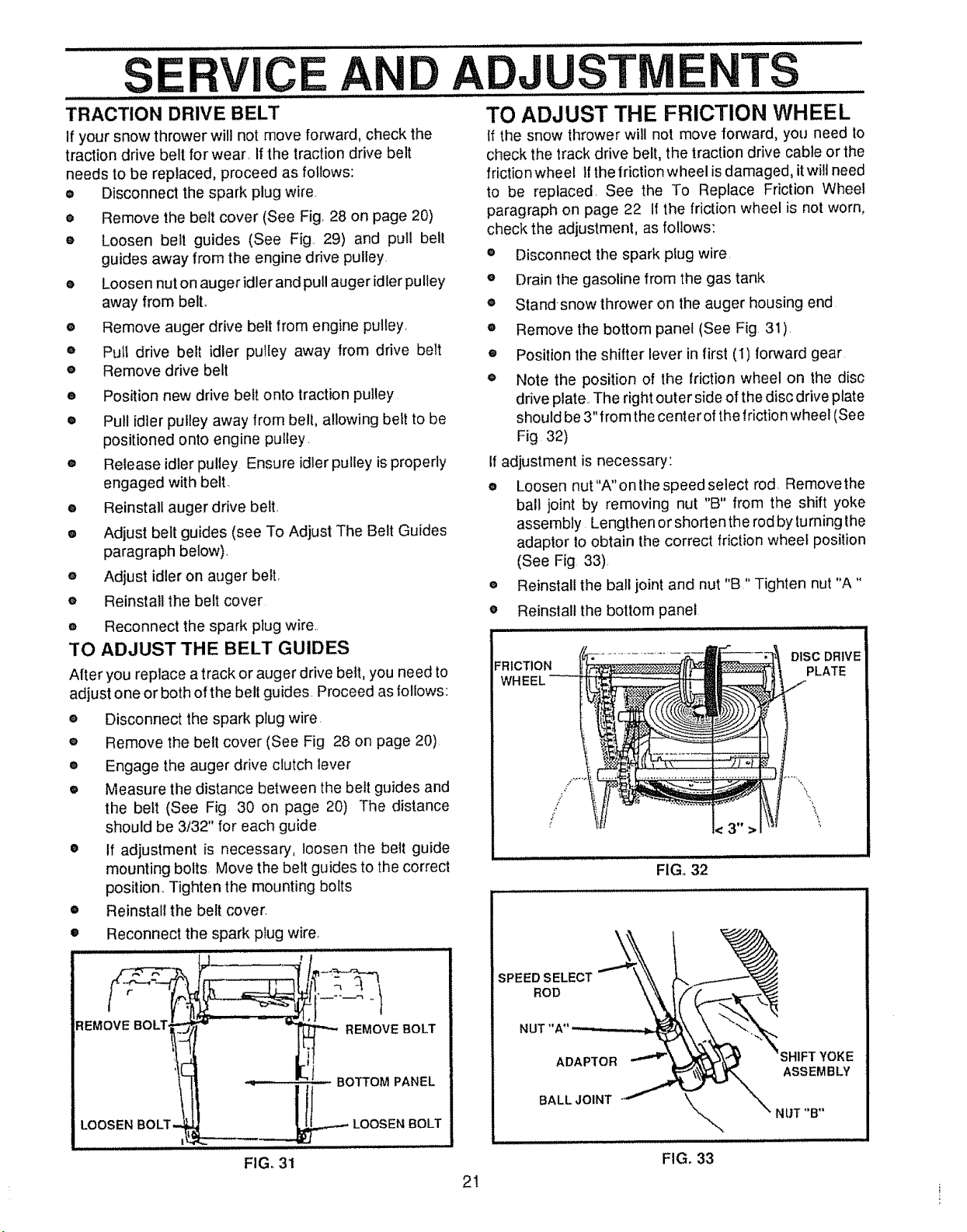
TO ADJUST THE FRICTION WHEEL
If the snow thrower will not move forward, you need to
check the track drive belt, the traction drive cable or the
friction wheel Ifthe friction wheel is damaged, it will need
to be replaced, See the To Replace Friction Wheel
paragraph on page 22 If the friction wheel is not worn,
check the adjustment, as follows:
e Disconnect the spark plug wire,
e Drain the gasoline from the gas tank
® Standsnow thrower on the auger housing end
® Remove the bottom panel (See Fig. 31),
® Position the shifter lever in first (1) forward gear
e Note the position of the friction wheel on the disc
drive plate,, The right outer side of the disc drive plate
should be 3" from the center of thefriction wheel (See
Fig 32)
;I adjustment is necessary:
e Loosen nut "A" on the speed select rod Removethe
ball joint by removing nut "B" from the shift yoke
assembly Lengthen or shortenthe rodby turning the
adaptor to obtain the correct friction wheel position
(See Fig 33),
e Reinstall the ball joint and nut "B" Tighten nut "A"
• Reinstall the bottom panel
FRICTION DISC DRIVE
FIG,, 32
PLATE
REMOVE BOLT,
LOOSEN BOLT,
FIG., 31
SPEED SELECT
21
ROD
NUT"A"
ADAPTOR
BALL JOINT
YOKE
ASSEMBLY
FIG, 33
SERVICE AND ADJUSTMENTS ..............
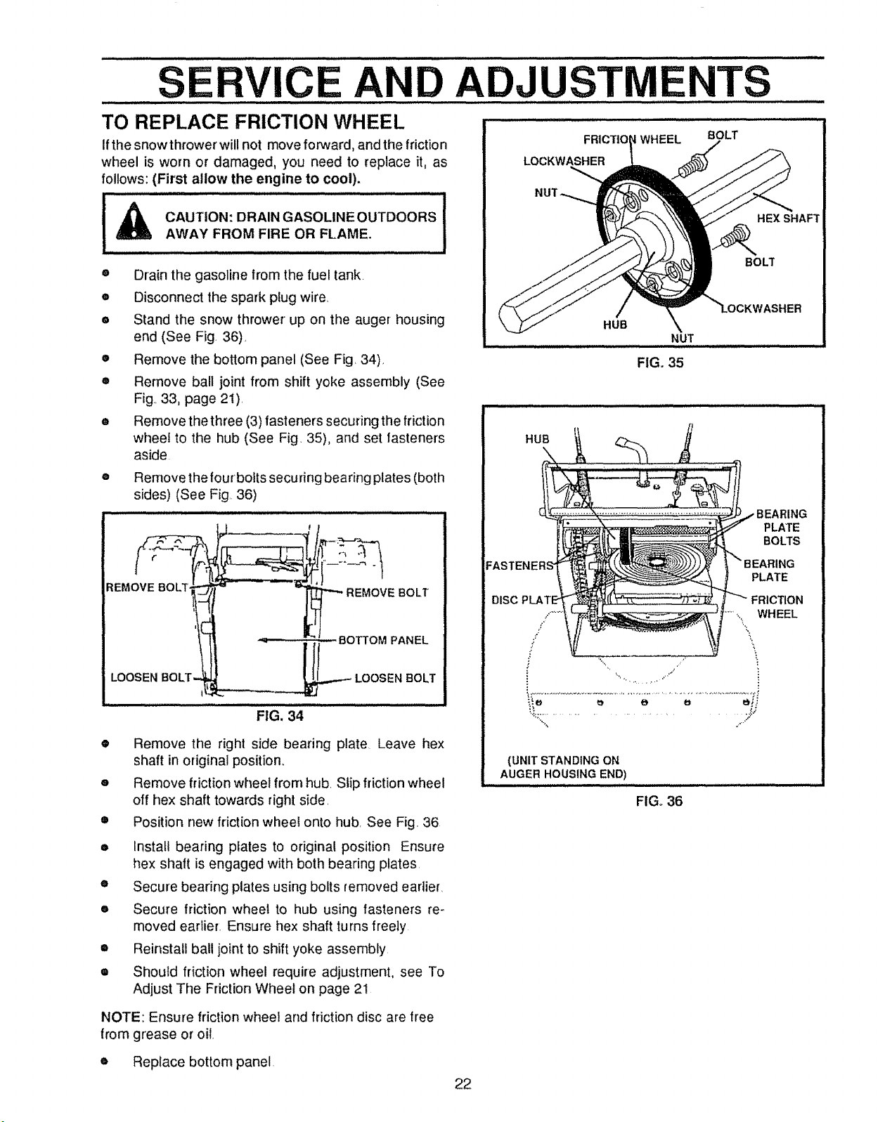
TO REPLACE FRICTION WHEEL
If the snow thrower will not move forward, and the frictio n
wheel is worn or damaged, you need to replace it, as
follows: (First allow the engine to cool).
CAUTION: DRAINGASOLINEOUTDOORS
AWAY FROM FIRE OR FLAME.
® Drain the gasoline from the fuel tank.
• Disconnect the spark plug wire
e Stand the snow thrower up on the auger housing
end (See Fig. 36).
• Remove the bottom panel (See Fig. 34)_
• Remove ball joint from shift yoke assembly (See
Fig.,33, page 2i).
• Remove the three (3)fasteners securing the friction
wheel to the hub (See Fig. 35), and set fasteners
aside
® Remove the four bofts securing bearing plates (both
sides) (See Fig. 36)
I
LOCKWASHER
HUB
FRtCTtO WHEEL
HUB
FIG. 35
BOLT
HEX SHAFT
BOLT
NUT
PLATE
BOLTS
FIG. 34
® Remove the right side bearing plate Leave hex
shaft in original position.
e Remove friction wheel from hub. Slip friction wheel
off hex shaft towards right side.
• Position new friction wheel onto hub. See Fig 36
Install bearing pfates to original position Ensure
hex shaft is engaged with both bearing plates
• Secure bearing plates using bolts removed earlier.
• Secure friction wheel to hub using fasteners re-
moved earlier. Ensure hex shaft turns freely
= Reinstall ball joint to shift yoke assembly.
• Should friction wheel require adjustment, see To
Adjust The Friction Wheel on page 21
DISC
(UNIT STANDING ON
AUGER HOUSING END)
FIG_ 36
PLATE
FRICTION
.....,..,\. WHEEL
r i
i
NOTE: Ensure friction wheel and friction disc are free
from grease or oil.
e Replace bottom panel
22
 Loading...