

Craftsman 536885471 Owner’s Manual
IMPORTANT MANUAL DO NOT THROW A WAY
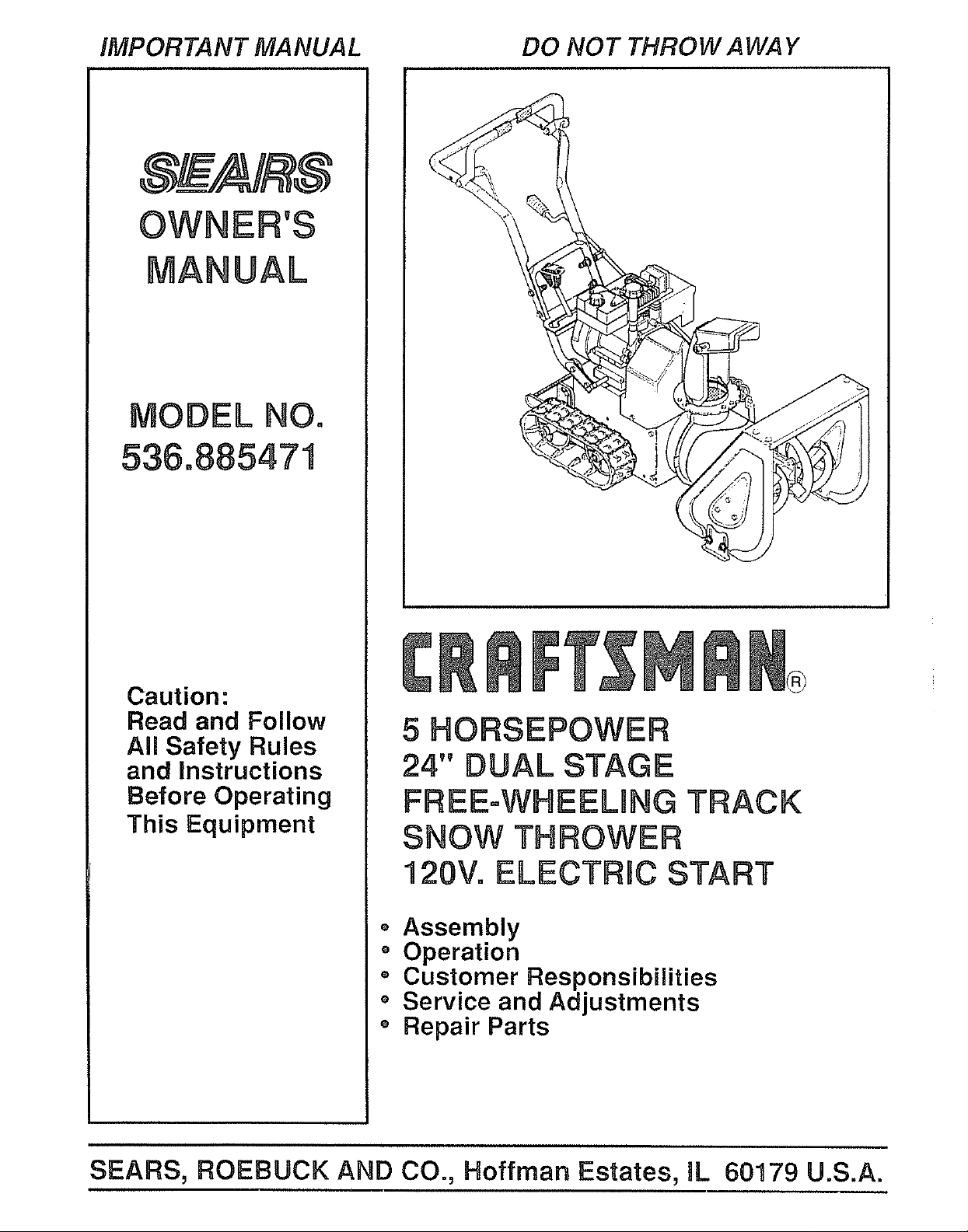
MODEL NO.
536°885471
Caution:
Read and Follow
All Safety Rules
and instructions
Before Operating
This Equipment
5 HORSEPOWER
24" DUAL STAGE
FREE=WHEELING ]'RACK
SNOW THROWER
120V. ELECTRIC START
• Assembly
o Operation
o Customer Responsibilities
o Service and Adjustments
o Repair Parts
SEARS, ROEBUCK AND CO., Hoffman Estates, IL 60179 U.S.A.
SAFETY RULES
CAUTION: ALWAYS DISCONNECT SPARK PLUG WIRE AND A
&
PLACE WIRE WHERE IT CANNOT CONTACT SPARK PLUG
TO PREVENT ACCIDENTAL STARTING WHEN SETTING-UP,
TRANSPORTING, ADJUSTING OR MAKING REPAIRS
IMPORTANT
SAFETY STANDARDS REQUIRE OPERATOR PRESENCE CONTROLS TO MINIMIZE THE
RISK OF INJURY. YOUR SNOW THROWER IS EQUIPPED WITH SUCH CONTROLS. DO NOT
ATTEMPT TO DEFEAT THE FUNCTION OF THE OPERATOR PRESENCE CONTROL UNDER
ANY CIRCUMSTANCES
TRAINING
1.
Read the operator's manual carefully_ Be
thoroughly familiar with the controls and the
proper use of the snow thrower. Know how to
stop the snow thrower and disengage the
controls quickly.
2_
Never allow children to operate the snow thrower'
and keep them away while it is operating. Never
allow adults to operate the snow thrower without
proper instruction. Do not carry passengers.
.
Keep the area of operation clear of all persons,
particularly small children, and pet&
4.
Exercise caution to avoid slipping or falling,
especially when operating in reverse.
PREPARATION
1. Thoroughly inspect the area where the snow
thrower Is to be used and remove all doormats,
sleds, boards, wires, and other foreign objects+
2. Disengage all clutches and shift into neutral
before starting the engine (motor')+
3+ Do not operatethe snowthrower without wearing
adequate winter outer garments+ Wear footwear
that will improve footing on slippery surfaces+
4. Handle fuel with care; it is highly flammable.
(a) Use an approved fuel container.
(b) Never remove fuel tank cap or add fuel to a
running engine or hot engine.
(c) Fill fuel tank outdoors with extreme care.
Never fill fuel tank indoors+
(d) Replace fuel tank cap securely and wipe up
spilled fuel+
(e) Never store fuel or snow thrower with fuel in
thetank inside of a building where fumes may
reach an open flame or spark_
(f) Check fuel supply before each use, allowing
space for expansion as the heat of the engine
(motor) and/or sun can cause fuel to expand.
5.
Use extension cords and receptacles as specified
by the manufacturer for all snow throwers with
electric drive motors or electric starting motor&
& Adjust the snow thrower height to clear gravel or
crushed rock surfaces
7_ Never attempt to make any adjustments while the
engine (motor) is running (except when
specifically recommended by the manufacturer).
8. Let engine (motor) and snow thrower adjust to
outdoor temperatures before starting to clear
snow=
9=
Always wear safety glasses or eye shields during
operation or while performing an adjustment or
repair to protect eyes from foreign objects that
may be thrown from the snow thrower
OPERATION
1. Do not put hands or feet near or under rotating
parts= Keep clear of the discharge opening at all
times,
2o Exercise extreme caution when operating on or
crossing gravel drives, walks, or roads. Stay alert
for hidden hazards or traffic_
3_
After striking a foreign object, stop the engine
(motor), remove the wire from the spark plug,
disconnect the cord on electric motors,
thoroughly inspect the snow thrower for any
damage, and repair the damage before restarting
and operating the snow thrower_
4_
If the snow thrower should start to vibrate
abnormally, stop the (motor) and check
Immediately for the cause_ Vibration is generally
a warning of trouble.
5.
Stop the engine (motor) whenever you leave the
operating position, before unclogging the auger/
impeller housing or discharge guide, and when
making any repairs, adjustments, or inspection&
,
When cleaning, repairing, or inspecting, make
certain the auger/impeller and all moving parts
have stopped. Disconnect the spark plug wire
and keep the wire away from the plug to prevent
accidental starting.
7_
Take all possible precautions when leaving the
snow thrower unattended_ Disengage the auger/
impeller, shift to neutral, stop engine, and
remove key.
2
SAFETY RULES
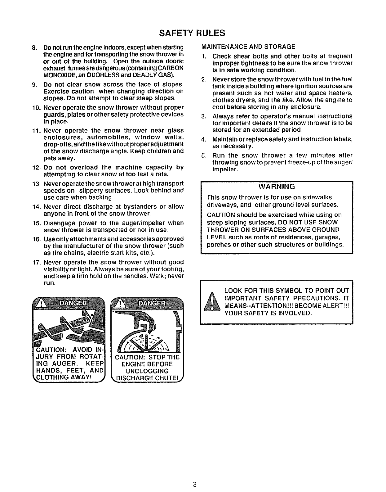
8,
Do not run the engine indoors,except when starting
the engine and for transporting the snow thrower in
or out of the building. Open the outside doors;
exhaust fumesaredangerous(containing CARBON
MONOXIDE, an ODORLESS and DEADLY GAS).
9. DO not clear snow across the face of slopes
Exercise caution when changing direction on
slopes. DO not attempt to clear steep slopes,
10. Never operate the snow thrower without proper
guards, plates or other safety protective devices
in place.
11. Never operate the snow thrower near glass
enclosures, automobiles, window wells,
drop-offs, and the like wit hout proper adjustment
of the snow discharge angle. Keep children and
pets away.
12. Do not overload the machine capacity by
attempting to clear snow at too fast a rate°
13. Neveroperatethe snowthrowerat high transport
speeds on slippery surfaces. Look behind and
use care when backing
14. Never direct discharge at bystanders or allow
anyone in front of the snow thrower
15o Disengage power to the auger/impeller when
snow thrower is transported or not in use.
16. Use only attachments and accessories approved
by the manufacturer of the snow thrower (such
as tire chains, electric start kits, etc,),
17. Never operate the snow thrower without good
visibility or light. Always be sure of your footing,
and keep a firm hold on the handles. Walk; never
run,
MAINTENANCE AND STORAGE
Check shear bolts and other bolts at frequent
improper tightness to be sure the snow thrower
is in safe working condition_
2_
Never store the snow thrower with fuel in the fuel
tank inside a building where ignition sources are
present such as hot water and space heaters,
clothes dryers, and the like. Allow the engine to
cool before storing in any enclosure
3o Always refer to operator's manual instructions
for important details If the snow thrower is to be
stored for an extended period°
4. Maintain or replace safety and instruction labels,
as necessary,
5. Run the snow thrower a few minutes after
throwing snow to prevent freeze-up of the auger/
impeller.
WARNING
This snow thrower is for use on sidewalks,
driveways, and other ground level surfaces.
CAUTION should be exercised while using on
steep sloping surfaces. DO NOT USE SNOW
THROWER ON SURFACES ABOVE GROUND
LEVEL such as roofs of residences, garages,
porches or other such structures or buildings.
LOOK FOR THIS SYMBOL TO POINT OUT
DISCHARGE CHUTE!
A IMPORTANT SAFETY PRECAUTIONS. ITMEANS--ATTENTIONH! BECOME ALERT!!!
YOUR SAFETY IS INVOLVED
CONGRATULATIONS on your purchase of a Sears
Craftsman Snow Thrower It has been designed, engi-
neered and manufactured to give you the best possible
dependability and performance
Should you experience any problem you cannot easily
remedy, please contact your nearest Sears Service
Center/Department We have competent, wel!-trained
technicians and the proper tools to service or repair this
unit
Please read and retain this manual The instructions will
enable you to assemble and maintain your snow thrower
properly Always observe the "SAFETY RULES."
MODEL
NUMBER 536 885471
SERIAL
NUMBER
DATE OF
PURCHASE
THE MODEL AND SERIAL NUMBERS WILL BE
FOUND ON A DECAL ATTACHED TO THE REAR
OF THE SNOW THROWER HOUSING
YOU SHOULD RECORD BOTH SERIAL NUMBER
AND DATE OF PURCHASE AND KEEP IN A SAFE
PLACE FOR FUTURE REFERENCE
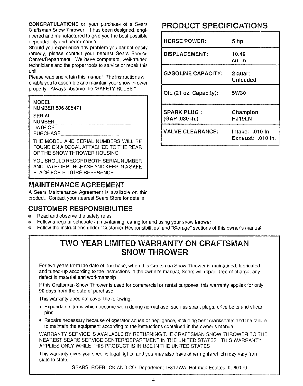
PRODUCT SPECIFICATIONS
HORSE POWER:
DISPLACEMENT: 10.49
GASOLINE CAPACITY: 2 quart
OIL (21 oz. Capacity): 5W30
SPARK PLUG :
(GAP .030 in.)
IVALVE CLEARANCE:
5hp
cu, in.
Unleaded
Champion
RJ19LM
Intake: .010 In,
Exhaust: .010 In.
MAINTENANCE AGREEMENT
A Sears Maintenance Agreement is available on this
product Contact your nearest Sears Store for details
CUSTOMER RESPONSIBILiTiES
e Read and observe the safety rules
e Follow a regular schedule in maintaining, caring for and using your snow thrower
e Follow the instructions under "Customer Responsibilities" and "Storage" sections of this owner's manual
TWO YEAR UMITED WARRANTY ON CRAFTSMAN
SNOW THROWER
For two years from the date of purchase, when this Craftsman Snow Thrower is maintained, lubricated
and tuned-up according to the instructions in the owner's manual, Sears will repair, free of charge, any
defect in material and workmanship
If this Craftsman Snow Thrower is used for commercial or rental purposes, this warranty applies for only
90 days from the date of purchase
This warranty does not cover the following:
• Expendable items which become worn during normal use, such as spark plugs, drive belts and shear
pins
o Repairs necessary because of operator abuse or negligence, including bent crankshafts and the failure
to maintain the equipment according to the instructionscontained in the owner's manual
WARRANTY SERVICE IS AVAILABLE BY RETURNING THE CRAFTSMAN SNOW THROWER TO THE
NEAREST SEARS SERVICE CENTER/DEPARTMENT IN THE UNITED STATES THIS WARRANTY
APPLIES ONLY WHILE THIS PRODUCT IS IN USE IN THE UNITED STATES
This warranty gives you specific legal rights, and you may also have other rights which may vary from
state to state
SEARS, ROEBUCK AND CO Department D/817WA, Hoffman Estates, IL 60179
4
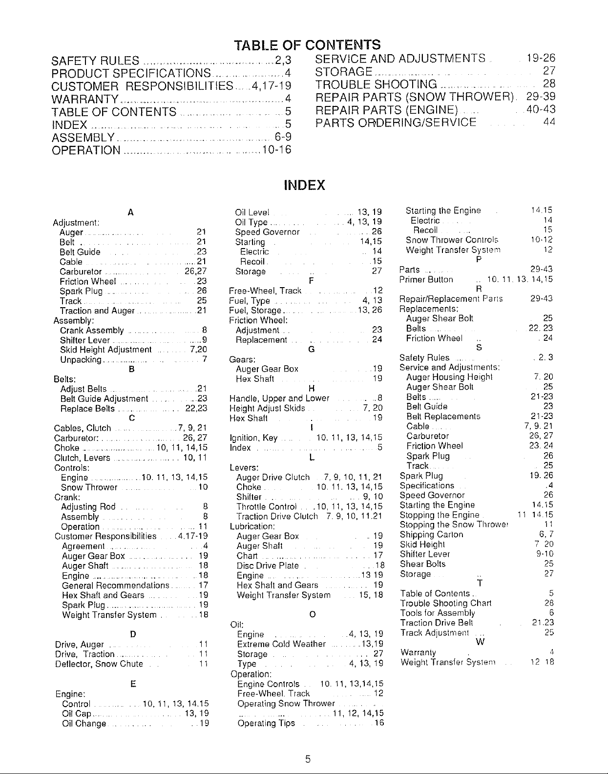
TABLE OF CONTENTS
SAFETY RULES ....................................... 2,3
PRODUCT SPECIFICATIONS ..................... 4
CUSTOMER RESPONSIBILITIES .......4,17-19
WARRANTY ........................................................... 4
TABLE OF CONTENTS .............................. 5
INDEX ............................................... 5
ASSEMBLY ....................................................... 6-9
OPERATION ....................................... 10-1 6
SERVICE AND ADJUSTMENTS 19-26
STORAGE ........................... 27
TROUBLE SHOOTING ..................... 28
REPAIR PARTS (SNOW THROWER) 29-39
REPAIR PARTS (ENGINE) ..... 40-43
PARTS OR,DERING/SERVlCE 44
INDEX
A
Adjustment:
Auger ..................... 21
Belt .................... 21
Belt Guide ........... 23
Cable ........................... 21
Carburetor ..................... 26,27
Friction Wheel .............. 23
Spark Plug ....................... 26
Track ................................ 25
Traction and Auger ........ 21
Assembly:
Crank Assembly .......... 8
Shifter Lever ....................................... 9
Skid Height Adjustment ........ 7,29
Unpacking ....................... 7
B
Belts:
Adjust Belts ........... 21
Belt Guide Adjustment .......... 23
Replace Belts ..................... 22,23
C
Cables, Clutch ...................... 7, 9, 21
Carburetor: ............................ 26, 27
Choke ......................... 10, 11, 14,15
Clutch, Levers ............................ 10, 11
Controls:
Engine ................. 10. 11, 13, 14,15
Snow Thrower ....... 10
Crank:
Adjusting Rod .......... 8
Assembly ............... 8
Operation ..................... t 1
Customer Responsibilities 4.17-19
Agreement ................... 4
Auger Gear Box ....................... 19
Auger Shaft ........................... 18
Engine ......................................... 18
General Recommendations .... 17
Hex Shaft and Gears ......... 19
Spark Plug ....................... 19
Weight Transfer System .... 18
D
Drive, Auger ........... 11
Drive, Traction ............ 1t
Deflector, Snow Chute 11
E
Engine:
Control .... 10, 11, 13, 14,15
Oil Cap .......... 13,19
Oil Change .............. 19
Oil Level t3, 19
Oil Type 4. !3. 19
Speed Governor 26
Starting 14.15
Electric 14
Recoi 15
Storage 27
F
Free-Whee Tract,. 12
Fuel, Type 4. 13
Fuel, Storage. 13.26
Friction Wheel:
Adjuslmen_ 23
Replacemen; . 24
G
Gears:
Auger Gear Box 19
Hex Shaft 19
H
Handle Upper ana Lower . .8
Height Adjust Skids 7.20
Hex Shaft 19
I
Ignition, Key 10. 11 13. 14.15
Index 5
L
Levers:
Auger Drive Clutch 7.9.10. 11.2"
Choke 10 11 13. 14.15
Shifter g. 10
ThrottleContro .10 11.13.!4.15
Traction Drive Cfutcll 7.9. 10. 11.21
LJbdcation:
Auger Gear Box 19
Auger Shaft 19
Chart . 17
Disc Drive Plate 18
Engine 13 19
Hex Shaft and Gears 19
Weight Transfer St s_err 15.18
O
Oil:
Engine ............ 4, 13, 19
Extreme Cold Weather .......... 13,19
Storage ............... 27
Type .... 4, 13, 19
Operation:
Engine Controls !0.11, 13,14,15
Free-Wheel. Track .......... 12
Operating Snow Thrower ...........
.................. 11, 12, 14,15
Operating Tips ........... 16
Starting the Engine 14.15
Electric 14
Recoil ..... 15
Snow Thrower Controls 10-12
Weight Transfer Syslem 12
P
Parts ......... 29-43
Primer Button .. 10. 11 13.14, t5
R
RepaidReplacement Paris 29-43
Replacements:
Auger Shear Bolt 25
Belts ............ 22.23
Friction Wheel 24
Safety Rules ....... 2.3
Service and Adjustments:
Auger Housing Height 7.20
Auger Shear Bolt 25
Belts .... 21_23
Beit Guide 23
Belt Replacements 21-23
Cable 7, 9.21
Carburetor 26, 27
Friction Wheel 23.24
Spark Plug 26
Track ........ 25
Spark Plug 19.26
Specifications .4
Speed Governor 26
Starting timeEngine 14,15
Stopping the Engine 11 14 15
Stopping the Snow Throwe_ 11
Shipping Carton 6, 7
Skid Height 7 20
Shifter Lever 9-10
Shear Bolts 25
Storage __ 27
Table of Contents. 5
Trouble Shooting ChaT1 28
Tools for Assembly 6
Traction Drive Bell 21 23
Track Adjustment .. 25
W
Warranty , 4
Weight Transfer System 12 18
5
CONTENTS
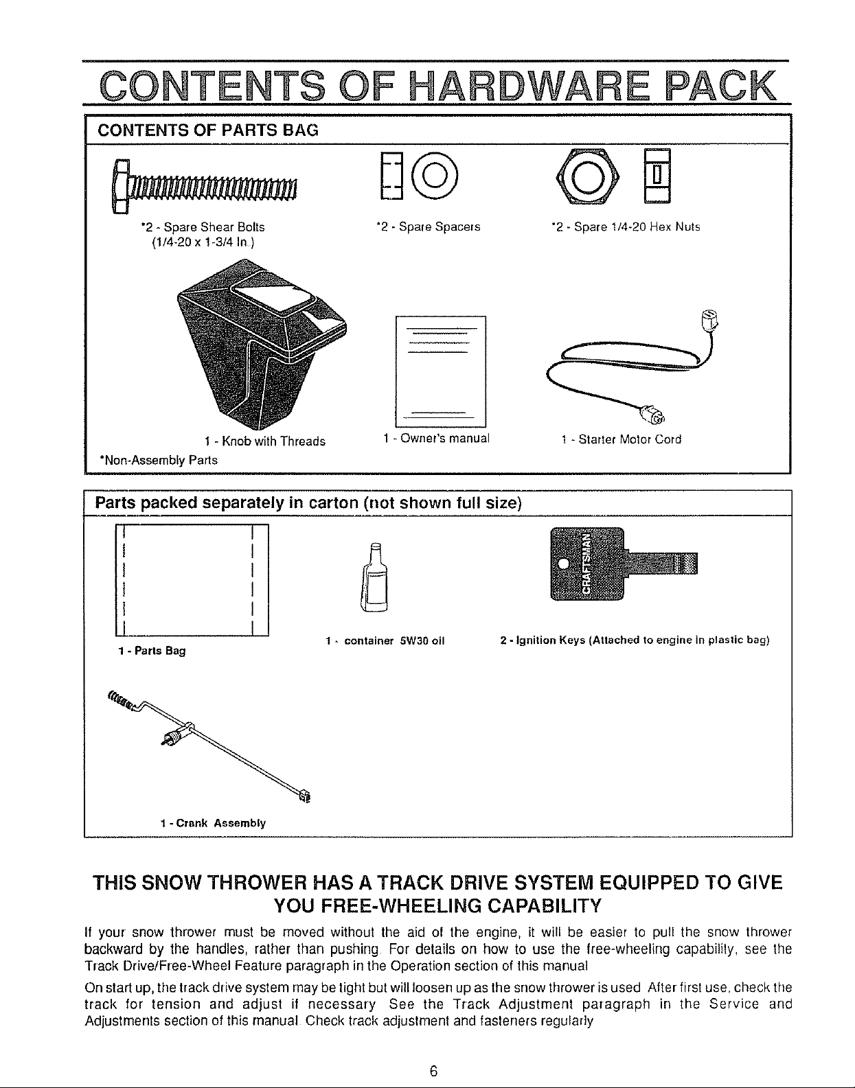
CONTENTS OF PARTS BAG
OF HARDWARE PACK
"2 - Spare Shear Bolts
(1/4-20 x 1-3/4 In )
1 - Knob with Threads
"Non-Assembly Parts
Parts packed separately in carton (not shown full size)
"2 - Spare Spacers "2- Spare 1/4_20Hex Nuts
m
1 - Owner's manual
I
I
I
I
I
--m
1 - Parts Bag
I
1- container 5W30 oil
2 - Ignition Keys (Attached to engine in plastic bag)
1 -Starter Motor Cord
1 - Crank Assembly
THiS SNOW THROWER HAS A TRACK DRIVE SYSTEM EQUIPPED TO GIVE
YOU FREE-WHEELING CAPABILITY
If your snow thrower must be moved without the aid of the engine, it will be easier to pull the snow thrower
backward by the handles, rather than pushing For details on how to use the free-wheeling capability, see the
Track Drive/Free-Wheel Feature paragraph in the Operation section of this manual
On start up, the track drive system may be tight but will loosen up as the snow thrower is used After first use, check the
track for tension and adjust if necessary See the Track Adjustment paragraph in the Service and
Adjustments section of this manual Check track adjustment and fasteners regularly
6
ASSEMBLY
TOOLS REQUIRED FOR ASSEMBLY
I - Knife (to cut carton and plastic ties)
2 - 1/2 inch wrenches (or adjustable wrenches)
2 - 9/16 inch wrenches (or adjustable wrenches)
2 - 3/4 inch wrenches (or adjustable wrenches)
1 - Pliers (to spread cotter pin)
1- Screwdriver
1 - Measuring tape or ruler
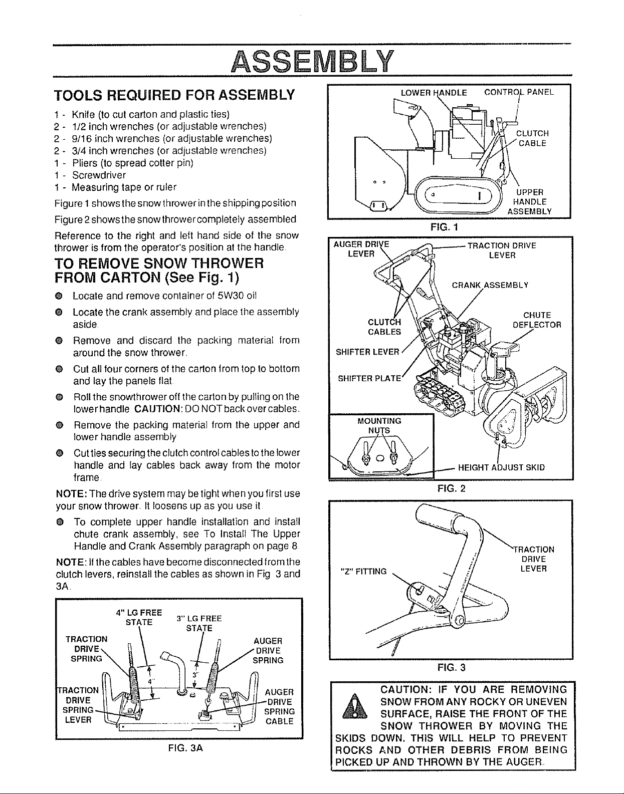
Figure I shows the snow thrower in the shipping position
Figure 2 shows the snowthrower completely assembled
Reference to the right and left hand side of the snow
thrower is from the operator's position at the handle
TO REMOVE SNOW THROWER
FROM CARTON (See Fig. 1)
@ Locate and remove container of 5W30 oil
e Locate the crank assembly and place the assembly
aside
O Remove and discard the packing material lrom
around the snow thrower
O Cut all four corners of the carton from top to bottom
and lay the panels flat
@ Roll the snowthrower off the carton by pulling on the
lower handle CAtJTION: DO NOT back over cables
@ Remove the packing material from the upper and
lower handle assembly
@ Cut ties securing the clutch control cables to the lower
handle and lay cables back away Irom the motor
frame
NOTE: The drive system may be tight when you first use
your snow thrower, It loosens up as you use it
@ To complete upper handle installation and install
chute crank assembly, see To Install The Upper
Handle and Crank Assembly paragraph on page 8
NOTE: If the cables have become disconnected from the
clutch levers, reinstall the cables as shown in Fig 3 and
3A
"Z" FITI'ING
LOWER ANDLE
FIG. 1
CRANK ASSEMBLY
FIG, 2
CONTRO_PANEL
LEVER
i
t
CLUTCH
UPPER
HANDLE
ASSEMBLY
DRIVE
LEVER
4" LG FREE
STATE 3" LG FREE
/ STATE
TRACTION \ / ,'_ AUGER
DRIVE\ _ _ / // /DRIVE
sP°,NO\ ;pR,NO
DR,VE --" / y_j DR,VE
SPR,N -. t ;P,,NG
LEVE. CASLE
FIG, 3A
FIG. 3
CAUTION: IF YOU ARE REMOVING
SNOW FROM ANY ROCKY OR UNEVEN
SURFACE, RAISE THE FRONT OF THE
SNOW THROWER BY MOVING THE
SKIDS DOWN. THIS WILL HELP TO PREVENT
ROCKS AND OTHER DEBRIS FROM BEING
PICKED UP AND THROWN BY THE AUGER
ASSE LY
HOW TO SET UP YOUR SNOW
THROWER
O
Your snow thrower is equipped with height adjust
skids (See Fig 2) on the outside of the auger
housing To adjust the skid height for different
conditions, see To Adjust Skid Height paragraph on
page 18
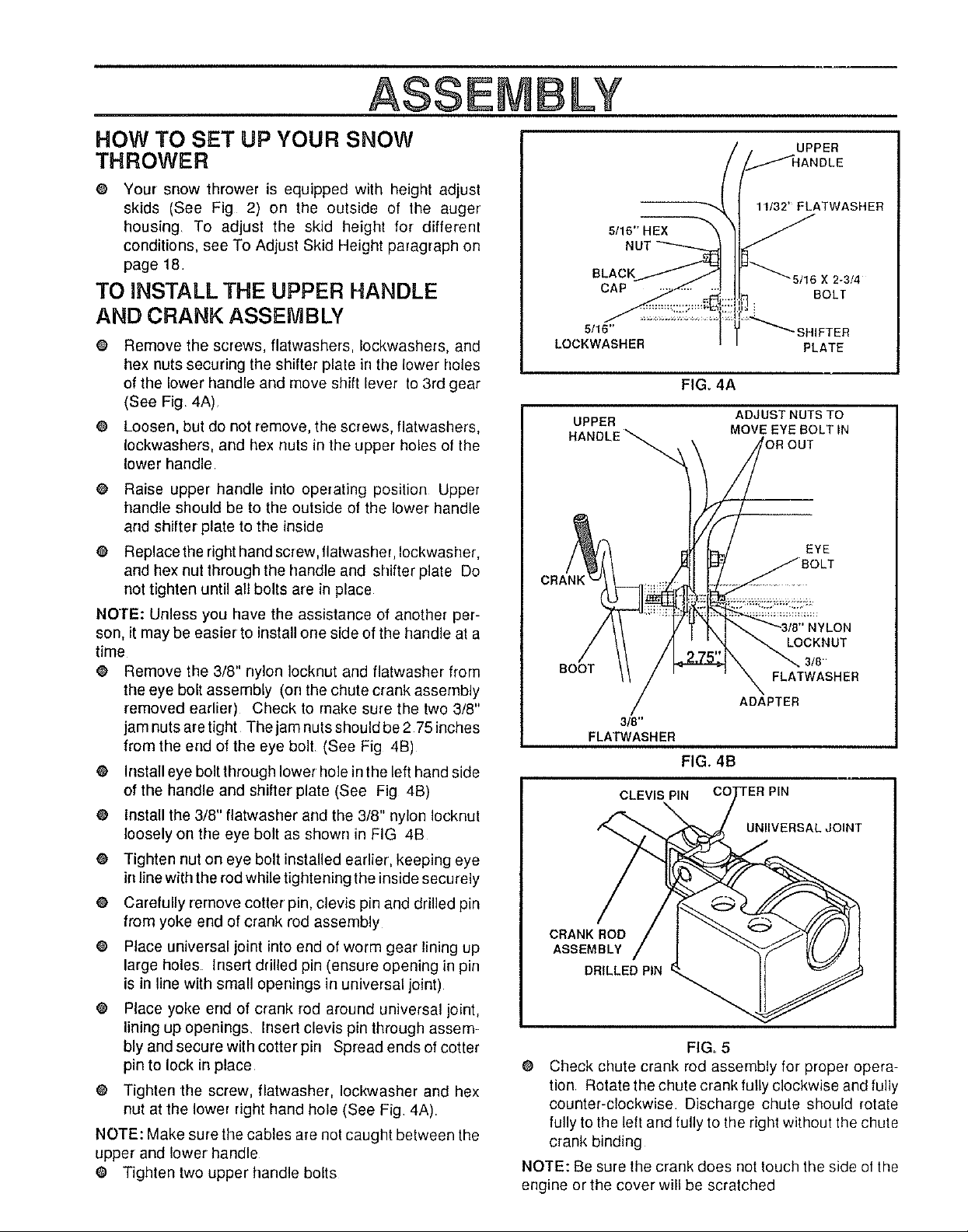
TO INSTALL THE UPPER HANDLE
AND CRANK ASSEMBLY
@ Remove the screws, fiatwashers, Iockwashers, and
hex nuts securing the shifter plate in the lower holes
of the lower handle and move shift lever to 3rd gear
(See Fig 4A)
@ Loosen, but do not remove, the screws, flatwashers,
Iockwashers, and hex nuts in the upper holes of the
lower handle
o
Raise upper handle into operating position Upper
handle should be to the outside of the lower handle
arrd shitter plate to the inside
o
Replace the right hand screw, flatwasher, Iockwasher,
and hex nut through the handle arrd shifter plate Do
not tighten until all bolts are in place
NOTE: Unless you have the assistance of another per-
son, it may be easier to install one side of the handle at a
time
@ Remove the 3/8" nylon Iocknut and flatwasher from
the eye bolt assembly (on the chute crank assembly
removed earlier) Check to make sure the two 3/8"
jam nuts are tight The jam nuts should be 2 75 inches
from the end of the eye bolt (See Fig 4B)
O Install eye bolt through lower hole in the left hand side
of the handle and shifter plate (See Fig 4B)
O install the 3/8" fiatwasher and the 3/8" nylon Iocknut
loosely on the eye bolt as shown in FIG 4B
O Tighten nut on eye bolt installed earlier, keeping eye
in line with the rod while tightening the inside securely
e Carefully remove cotter pin, clevis pin and drilled pin
from yoke end of crank rod assembly
O Place universal joint into end of worm gear lining up
large holes Insert drilled pin (ensure opening in pin
is in line with small openings in universal joint)
o
Place yoke end of crank rod around universal joint,
lining up openings, Insert clevis pin through assem-
bly and secure with cotter pin Spread ends of cotter
pin to lock in place
O Tighten the screw, flatwasher, Iockwasher arrd hex
nut at the lower right hand hole (See Fig 4A)
NOTE: Make sure the cables are not caught between the
upper and lower handle
O Tighten two upper handle bolts
UPPER
11/32' FLATWASHEB
5/16" HEX
BLACK 16 X 2-3/4
CAP BOLT
5/16" 'SHIFTER
LOCKWASHER PLATE
FIGo 4A
UPPER ADJUST NUTS TO
HANDLE _ MOVE EYE BOLT IN
OUT
"'4
EYE
CLON
LOCKNUT
BOOT
ADAPTER
3/8"
FLATWASHER
FIG. 4B
CLEVIS PIN TER PIN
UNllVERSAL JOINT
CRANK ROD
ASSEMBLY
DRILLED PIN
FIG. 5
O Check chute crank rod assembly for proper opera-
tion Rotate the chute crank fully clockwise and fully
counter-clockwise Discharge chute should rotate
fully to the left and fully to the right without tile chute
crank binding
NOTE: Be sure the crank does not touch the side of the
engine orthe cover will be scratched
3/8"
FLATWASHER
i
ASS LY
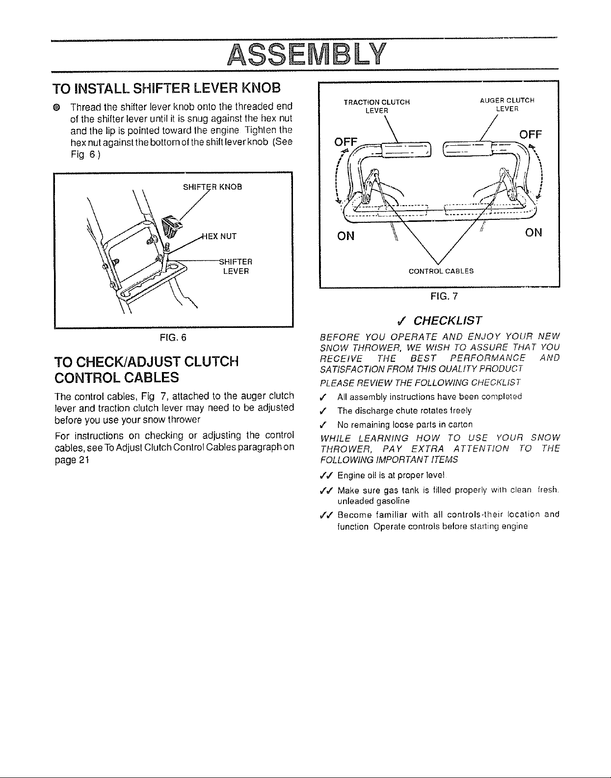
TO INSTALLSHIFTER LEVER KNOB
@ Thread the shifter lever knob onto the threaded end
of the shifter lever until it is snug against the hex nut
and the lip is pointed toward the engine Tighten the
hex nut against the bottom of the shift lever knob (See
Fig 6 )
SHIFT RKNOB
\
TRACTION CLUTCH
LEVER
AUGER CLUTCH
LEVER
OFF
NUT
"SHIFTER
LEVER
FIG, 6
TO CHECK/ADJUST CLUTCH
CONTROL CABLES
The control cables, Fig 7, attached to the auger clutch
lever and traction clutch lever may need to be adjusted
before you use your snow thrower
For instructions on checking or adjusting the control
cables, see To Adjust Clutch Conlrol Cables paragraph on
page 21
ON
CONTROLCABLRS
FIG. 7
ON
,# CHECKLIST
BEFORE YOU OPERATE AND ENJOY YOUR NEW
SNOW THROWER, WE WISH TO ASSURE THAT YOU
RECEIVE THE BEST PERFORMANCE AND
SATISFACTION FROM THIS QUALITY PRODUCT
PLEASE REVIEW THE FOLLOWING CHECKLIST
,( All assembly instructions have been completed
,/ The discharge chute rotates freely
,/ No remaining loose parts in carton
WHILE LEARNING HOW TO USE YOUR SNOW
THROWER, PAY EXTRA ATTENTION TO THE
FOLLOWING IMPORTANT ITEMS
€',/ Engine oil is at proper level
7,/" Make sure gas tank is filled properly wilh clean fresh
unleaded gasoline
,/,f Become familiar with afl controls-their location and
function Operate controls before starting engine
m
OPERATION
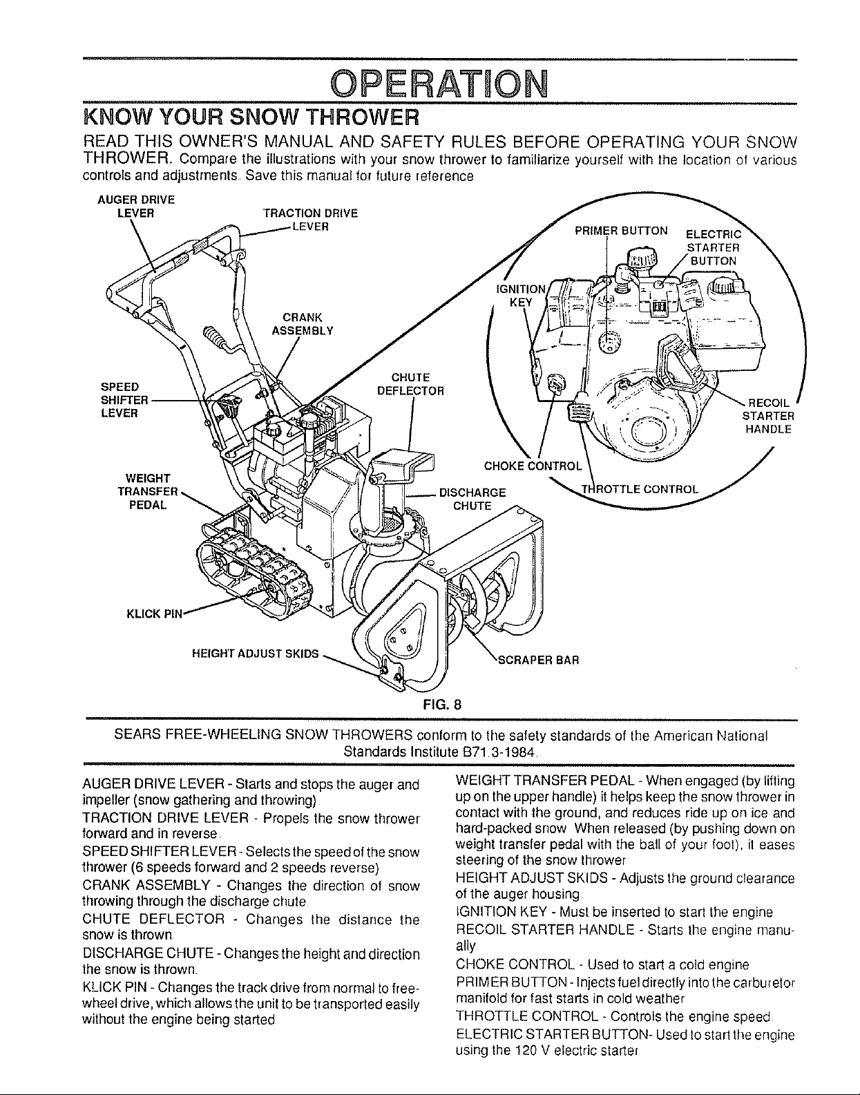
KNOW YOUR SNOW THROWER
READ THIS OWNER'S MANUAL AND SAFETY RULES BEFORE OPERATING YOUR SNOW
THROWER,. Compare the illustrations with your snow thrower to familiarize yourself with the location of various
controls and adjustments Save this manual for future reference
AUGER DRIVE
LEVER TRACTIONDRIVE
PRIMERBUTTON
STARTER
CRANK
ASSEMBLY
SPEED
LEVER
WEIGHT
PEDAL
HEIGHT ADJUST SKIDS
CHUTE
DEFLECTOR
CHuTIHOKECON_
FIG. 8
SEARS FREE-WHEELING SNOW THROWERS conform to the safety standards of the American National
Standards Institute B71 3-1984
IL
STARTER
HANDLE
AUGER DRIVE LEVER - Starts and stops the auger and
impeller (snow gathering and throwing)
TRACTION DRIVE LEVER - Propels the snow thrower
forward and in reverse
SPEED SHIFTER LEVER- Selects the speed of the snow
thrower (6 speeds forward and 2 speeds reverse)
CRANK ASSEMBLY - Changes the direction of snow
throwing through the discharge chute
CHUTE DEFLECTOR - Changes the distance the
snow is thrown
DISCHARGE CHUTE - Changes the height arrd direction
the snow is thrown,
KLICK PIN - Changes the track drive from normal to free-
wheel drive, which allows the unit to be transported easily
without the engine being started
WEIGHT TRANSFER PEDAL - When engaged (by lifting
up on the upper handle) it helps keep the snow thrower in
contact with the ground, and reduces ride up on ice and
hard-packed snow When released (by pushing down on
weight transfer pedal with the ball of your foot), it eases
steering of the snow thrower
HEIGHT ADJUST SKIDS - Adjusts the ground cIearance
of the auger housing
IGNITION KEY - Must be inserted to start the engine
RECOIL STARTER HANDLE - Starts the engine manu-
ally
CHOKE CONTROL - Used to start a cold engine
PRIM ER BUTTON - Injects fuel directly into thecarburetor
manifold for fast starts in cold weather
THROTTLE CONTROL - Controls the engine speed
ELECTRIC STARTER BUTTON- Used to start tile engine
using the 120 V electric starter
OPERATnON
The operation of any snow thrower can result in foreign objects being thrown into the
eyes, which can result in severe eye damage Always wear safety glasses or eye
shields while operating the snow thrower
We recommend standard safety glasses available at SEARS Retail Store or Service
Center
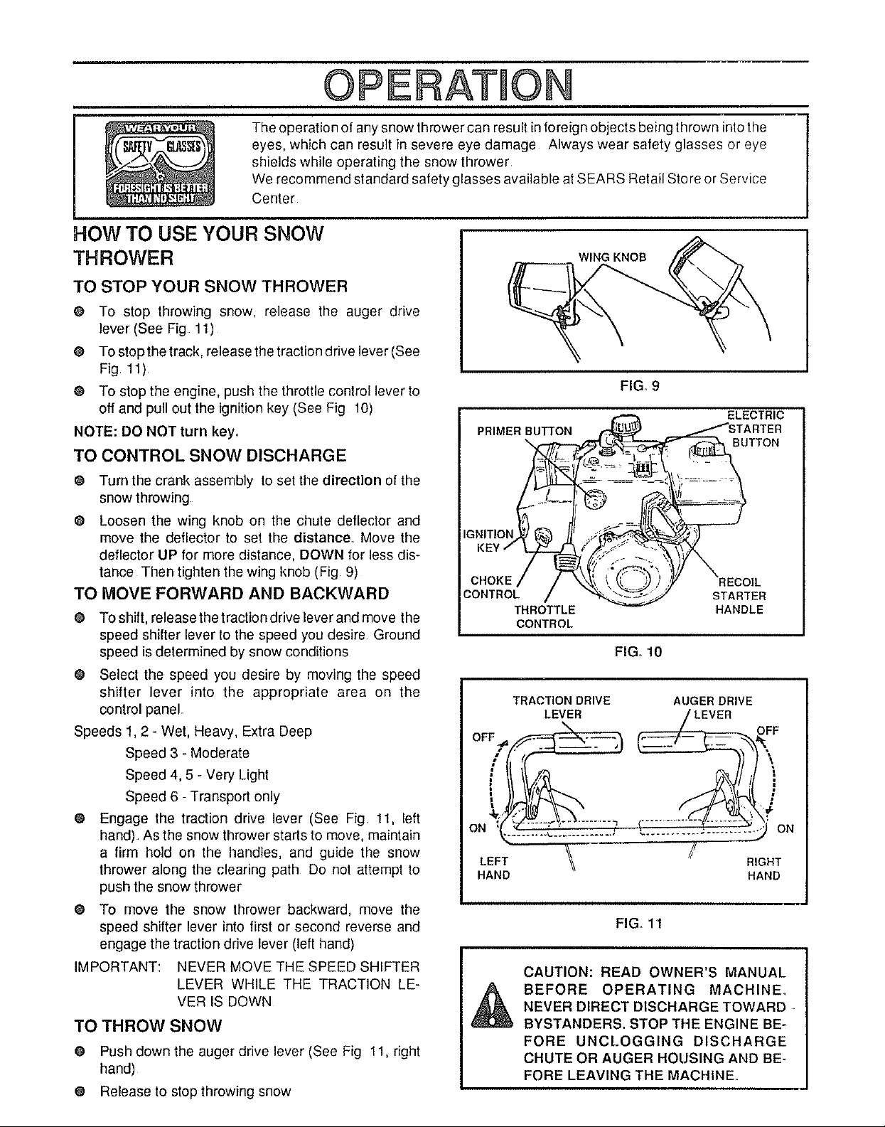
HOW TO USE YOUR SNOW
THROWER
TO STOP YOUR SNOW THROWER
@ To stop throwing snow, release the auger drive
lever (See Fig 11)
@ To stopthe track, release the traction drive lever (See
Fig 11)
¢ To stop the engine, push the throttle control lever to
off and pull out the ignition key (See Fig 10)
NOTE: DO NOT turn key,
TO CONTROL SNOW DISCHARGE
@ Turn the crank assembly to set the direction of the
snow throwing
@ Loosen the wing knob on the chute deflector and
move the deflector to set the distance Move the
deflector UP for more distance, DOWN for less dis-
tance Then tighten the wing knob (Fig 9)
TO MOVE FORWARD AND BACKWARD
@ Toshift, releasethetractiondriveleverandmove the
speed shifter lever to the speed you desire Ground
speed is determined by snow conditions
@ Select the speed you desire by moving the speed
shifter lever into the appropriate area on the
control panel
Speeds 1,2 - Wet, Heavy, Extra Deep
Speed 3 - Moderate
Speed 4, 5 - Very Light
Speed 6 -Transport only
@ Engage the traction drive lever (See Fig 11, left
hand) As the snow thrower starts to move, maintain
a firm hold on the handles, and guide the snow
thrower along the clearing path Do not attempt to
push the snow thrower
@ To move the snow thrower backward, move the
speed shifter lever into first or second reverse and
engage the traction drive lever (left hand)
IMPORTANT: NEVER MOVE THE SPEED SHIFTER
LEVER WHILE THE TRACTION LE-
VER IS DOWN
TO THROW SNOW
0 Push down the auger drive lever (See Fig 11, right
hand)
@ Release to stop throwing snow
WING KNOB
CHOKE
CONTROL
THROTTLE
CONTROL
TRACTION DRIVE
LEVER
OFF,__
DN :_ T;21"22
LEFT
HAND
CAUTION: READ OWNER'S MANUAL
BEFORE OPERATING MACHINE,
NEVER DIRECT DISCHARGE TOWARD
BYSTANDERS. STOP THE ENGINE BE-
FORE UNCLOGGING DISCHARGE
CHUTE OR AUGER HOUSING AND BE-
FORE LEAVING THE MACHINE,
FIG. 9
STARTER
HANDLE
FIGo 10
AUGER DRIVE
_] ON
RIGHT
HAND
FIGo11
 Loading...