

Craftsman 536885410 Owner’s Manual
OWNE 'S
UAL
MODEL NO=
536.885410
Caution-.
Read and Follow
all Safety Rules
and instructions
Before Operating
This Equipment
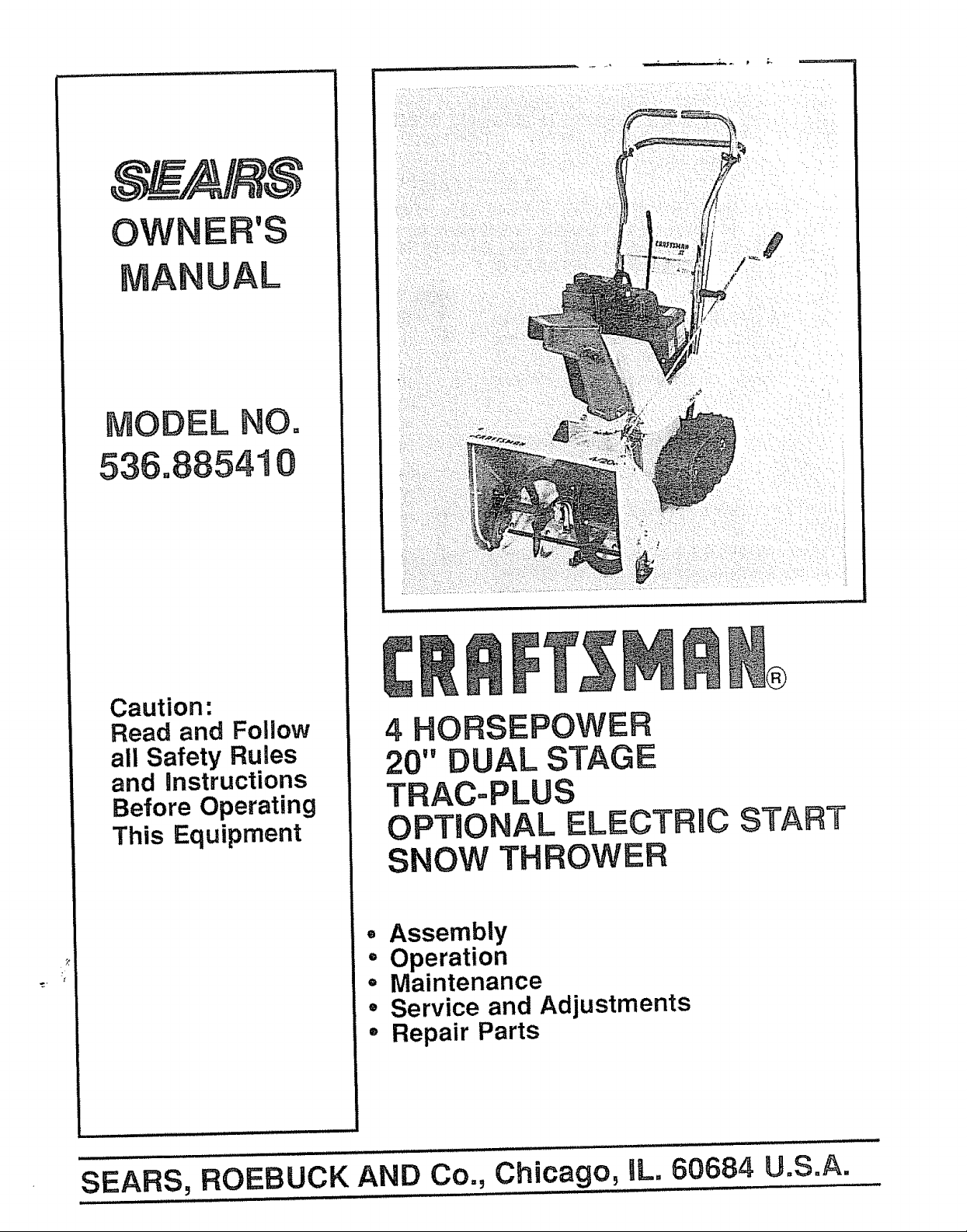
4 HORSEPOWER
20" DUAL STAGE
TRAC=PLUS
OPTIONAL ELECTRBC START
SNOW THROWER
• Assembly
o Operation
= Maintenance
° Service and Adjustments
- Repair Parts
SEARS, ROEBUCK AND Co., Chicago, aL.60684 U.SoA.
SAFETY RULES
CAUTION: ALWAYS DISCONNECT SPARK PLUG WIRE AND A
PLACE WIRE WHERE IT CANNOT CONTACT SPARK PLUG TO
PREVENT ACCIDENTAL STARTING WHEN SETTING-UP,
TRANSPORTING, ADJUSTING OR MAKING REPAIRS.
&
IMPORTANT
SAFETY STANDARDS REQUIRE OPERATOR PRESENCE CONTROLS TO MINIMIZE
THE RISK OF INJURY. YOUR SNOW THROWER IS EQUIPPED WITH SUCH CONTROLS.
DO NOT ATTEMPT TO DEFEAT THE FUNCTION OF THE OPERATOR PRESENCE
CONTROL UNDER ANY CIRCUMSTANCES,
BEFORE USE
® Read the owner's manual carefully. Be thor-
oughly familiar with the controls and the proper
use of the snow thrower. Know how to stop the
snow thrower and disengage the controls
quickly.
® Do not operate the snow thrower without wear-
ing adequate winter outer garments. Wear
footwear that will improve footing on slippery
surfaces°
® Keep the area of operation clear of all persons,
particularly small children, and pets.
e Thoroughly inspect the area where the snow
thrower is to be used and remove all doormats,
sleds, boards, wires, and other foreign objects.
e Use extension cords and receptacles as speci-
fied by the manufacturer for all snow throwers
with electric drive motors or electric starting
motors°
® Use only attachments and accessories ap-
proved by the manufacturer of the snow thrower
(such as tire chains, electric start kits, etco)
e Never operate the snow thrower without good
visibility or light, Always be sure of your footing,
and keep a firm hold on the handles, Walk;
never run.
e This snow thrower is for use on sidewalks,
driveways, and other ground level surfaces.
CAUTION should be exercised while using on
steep sloping surfaces. DO NOT USE SNOW
THROWER ON SURFACES ABOVE
GROUND LEVEL such as reofs of residences,
garages, porches or other such structures or
buildings.
= Check shear bolts and other bolts at frequent
intervals for proper tightness to be sure the
snow thrower is in safe working condition.
e Disengage all clutches and shift into neutral
before starting the engine
® Adjust the snow.thrower height to clear gravel
or crushed rock surface.
® Let engine and snow thrower adjust to outdoor
temperatures before starting to Clear snow.
FUEL .SAFETY
e Handle fuel with care; it is highly flammable.
e Use an approved fuel container.
® Check fuel supply before each use, allowing
space for expansion as the heat of the engine
and/or sun can cause fuel to expand,
® Fill fuel tank outdoors with extreme care. Never
fill fuel tank indoors.
® Replace fuel tank cap securely and wipe up
spilled fuel,
e Never remove fuel tank cap or add fuel to a
runningengine or hot engine_
® Never store fuel or snow thrower with fuel in the
tank inside of a building where fumes may
reach an open flame or spark.
OPERATING SAFETY
® Never allow children or young teenagers to
operate the snow thrower and keep them away
while it is operating. Never allow adults to
operate the snow thrower without proper in-
struction. Do not carry passengers.
® Always wear safety glasses or eye shields
during operation orwhile performing an adjust-
ment or repair to protect eyes from foreign
objects that may be thrown from the snow
thrower.
® Exercise extreme caution when operating on
or crossing gravel drives, walks, or roads, Stay
alert for hidden hazards or traffic°
o Do not put hands or feet near or under rotating
parts. Keep clear of the discharge opening at
all times.
e Exercise caution to avoid slipping or falling, es-
pecially when operating in reverse.
® Do not clear snow across the face of slopes.
Exercise caution when changing direction on
slopes. Do not attempt to clear steep slopes,
® Never operate the snowthrower without proper
guards, plates or other safety protective de-
vices in place.
SAFETY RU LES
e Never operate the snow thrower near glass en-
closures, automobiles, window wells, drop-
offs, and the like without proper adjustment of
the snow discharge angle,, Keep children and
pets away.
® Never operate the snow thrower at high trans-
port speeds on slippery surfaces,. Look behind
and use care when backing.
e Never direct discharge at bystanders or allow
anyone in front of the snow throwers.
o Do not run the engine indoors, except when
starting the engine and for transporting the
snow thrower in or out of the building. Open the
outside doors; exhaust fumes are dangerous
(containing CARBON MONOXIDE, an ODOR-
LESS and DEADLY GAS)_
Take all possible precautions when leaving the
snow thrower unattended., Disengage the
auger!impeller, shift to neutral, stop engine,
and remove key,.
® Do not overload the machine capacity by at-
tempting to clear snow at too fast a rate.,
SAFE STORAGE
e Always referto owner's manual instructions for
important details if the snow thrower is to be
stored for an extended period,
e Disengage power to the auger/impeller when
snow thrower is transported or not in use_
o Never store the snow thrower with fuel in the
fuel tank inside a building where ignition sources
are present such as hot water and space
heaters, clothes dryers, and the like.. A_low the
engine to cool before storing in any enclosure.
REPAIRtADJUSTMENTS SAFETY
e After striking a foreign object, stop the engine
(motor), remove the wire from the spark plug,
disconnect the cord on electric motors, thor-
oughly inspect the snow thrower for any dam-
age, and repair the damage before restarting
and operating the snow thrower°
o If the snow thrower should start to vibrate
abnormally, stop the engine (motor) and check
immediately for the causer Vibration is gener-
ally a warning of trouble_.
® Stop the engine (motor) whenever you leave
the operating position, before unclogging the
auger/impeller housing or discharge guide,
and when making any repairs, adjustments, or
inspections_
o When cleaning, repairing, or inspecting, make
certain the auger/impeller and all moving parts
have stopped° Disconnect the spark plug wire
and keep the wire away from the ptug to
prevent accidental starting.
o Never attempt to make any adjustments while
the engine is running (except when specifically
recommended by manufacturer).
o Maintain or replace safety and instruction
labels, as necessary.
® Run the snow thrower a few minutes after
throwing snow to prevent freeze-up of the
auger/impeller,.
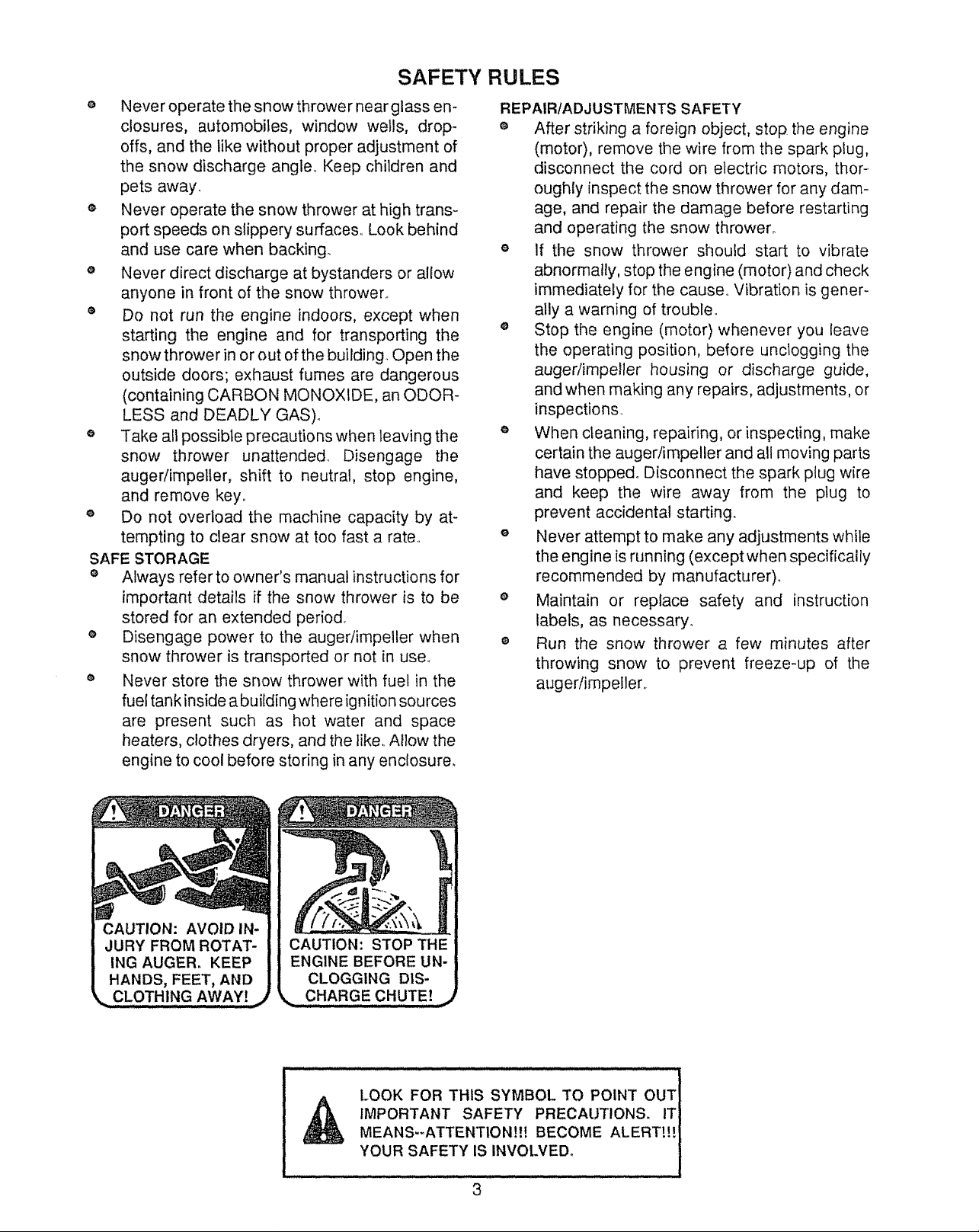
CAUTION: AVOID IN-
JURY FROM ROTAT-
ING AUGER. KEEP
HANDS, FEET, AND
LOOK FOR THIS SYMBOL TO POINT OUT
IMPORTANT SAFETY PRECAUTIONS. IT]
MEANS--ATTENTION!!! BECOME ALERTt!! i
YOUR SAFETY IS INVOLVED.
3
CONGRATULATIONS on your purchase of a Sears
Craftsman Snow Thrower.. It has been designed, engi-
neered and manufactured to give you the best possible
dependability and performance.
Should you experience any problem you cannot easily
remedy, please contact your nearest Sears Service Cen-
tedDepartment. We have competent, well-trained tech-
nicians and the proper tools to service or' repair this unit..
Please read and retain this manual.. The instructions will
enable you to assemble and maintain your snow thrower
properly.. Always observe the "SAFETY RULES/'
MODEL
NUMBER 536.885410
SERIAL
NUMBER
DATE OF
PURCHASE
THE MODEL AND SERIAL NUMBERS WILL BE
FOUND ON A DECAL ATTACHED TO THE REAR
OF THE SNOW THROWER HOUSING
YOU SHOULD RECORD BOTH SERIAL NUMBER
AND DATE OF PURCHASE AND KEEP IN ASAFE
PLACE FOR FUTURE REFERENCE..
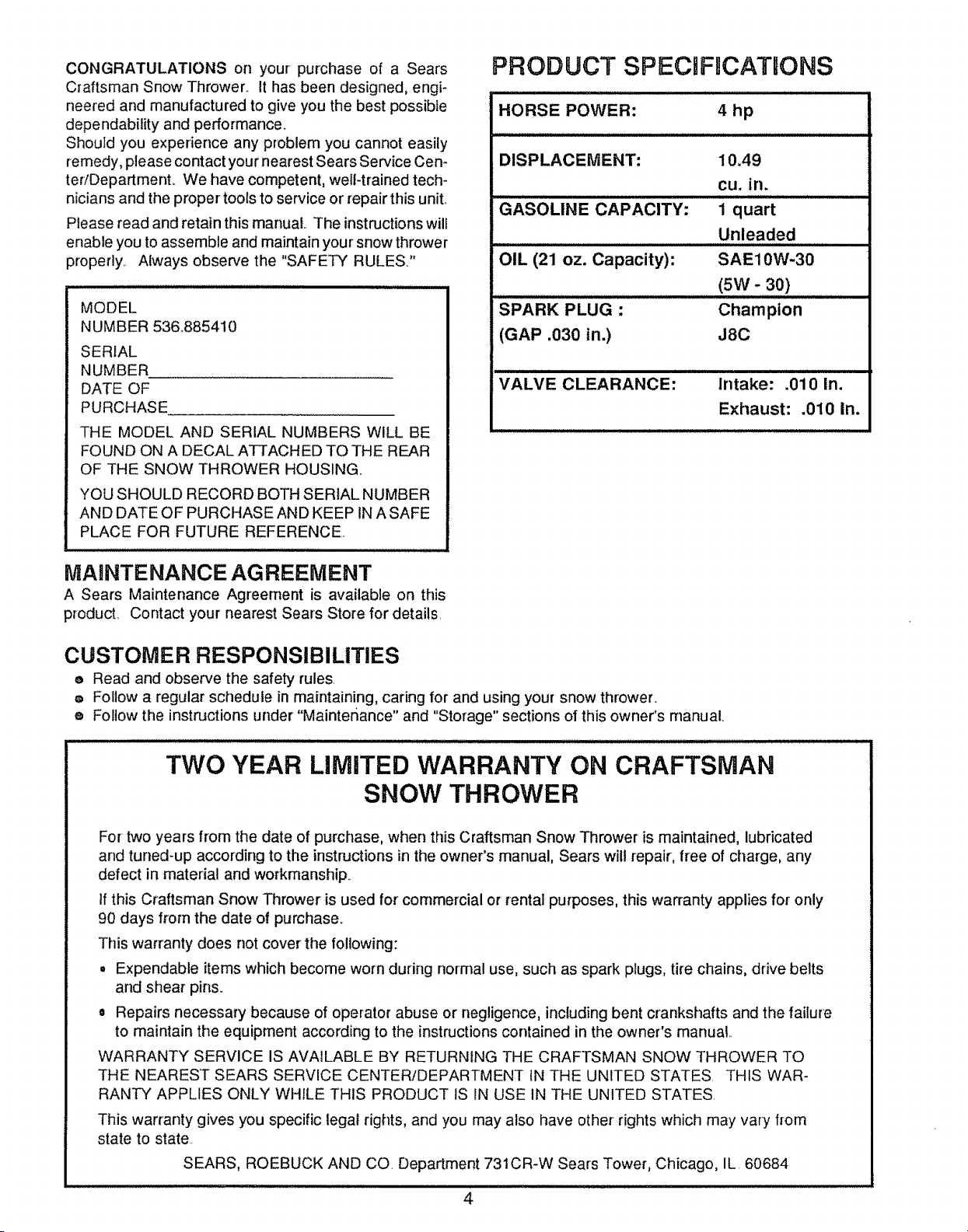
PRODUCT SPECiFmCATIONS
HORSE POWER: 4 hp
DISPLACEMENT:
GASOLINE CAPACITY:
OIL (21 oz. Capacity):
SPARK PLUG -
(GAP .030 in.)
VALVE CLEARANCE:
10A9
cu. in.
1 quart
Unleaded
SAE10W-30
(5W - 30)
Champion
J8C
Intake: .010 In.
Exhaust: .010 In.
MAINTENANCE AGREEMENT
A Sears Maintenance Agreement is available on this
producL Contact your nearest Sears Store for details,
CUSTOMER RESPONSIBILITIES
e Read and observe the safety rules
o Follow a regular schedule in maintaining, caring for and using your snow thrower.
e Follow the instructions under "Maintenance" and "Storage" sections of this owner's manual.
TWO YEAR LIMITED WARRANTY ON CRAFTSMAN
SNOW THROWER
For two years from the date of purchase, when this Craftsman Snow Thrower is maintained, lubricated
and tuned-up according to the instructions inthe owner's manual, Sears wilt repair, free of charge, any
defect in material and workmanship.
If this Craftsman Snow Thrower is used for commercial or rental purposes, this warranty applies for only
90 days from the date of purchase.
This warranty does not cover' the following:
• Expendable items which become worn during normal use, such as spark plugs, tire chains, drive belts
and shear pins.
o Repairs necessary because of operator abuse or negligence, including bent crankshafts and the failure
to maintain the equipment according to the instructions contained in the owner's manual
WARRANTY SERVICE IS AVAILABLE BY RETURNING THE CRAFTSMAN SNOW THROWER TO
THE NEAREST SEARS SERVICE CENTER/DEPARTMENT IN THE UNITED STATES THIS WAR-
RANTY APPLIES ONLY WHILE THIS PRODUCT IS IN USE IN THE UNITED STATES.
This warranty gives you specific legal rights, and you may also have other rights which may vary from
state to state.
SEARS, ROEBUCK AND CO. Department 731CR-W Sears Tower, Chicago, IL 60684
4
TABLE OF CONTENTS
SAFETY RULES ...................................................2,3
PRODUCT SPECIFICATIONS ..............................4
CUSTOMER RESPONSIBILITIES ................. 4
WARRANTY .............................................................4
TABLE OF CONTENTS ...........................................5
INDEX .................................................................... 5
ASSEMBLY ....................................................... 6-8
OPERATION ................................................... 9-t3
MAINTENANCE ...............................................14-15
SERVICE AND ADJUSTMENTS ..............16-22
STORAGE .................................................................23
SERVICE RECOMMENDATIONS ..................24
TROUBLE SHOOTING .........................................25
REPAIR PARTS (SNOWTHROWER) ....26-33
REPAIR PARTS (ENGINE) ....................... 34-37
PARTS ORDERINGISE RVlCE ..... Back Cover
iNDEX
A
Adjustment:
Auger ..............................................................17
Belt ..................................................................t7
Belt Guides ...................................................tg
Cables ...............................................................17
Carburetor .............................................22
Friction Wheel ..........................................t 9
Chute Crank .............................................16
Scraper Bar .................................................16
Spark Plug ...............................................22
Track ..............................................................21
Traction and Auger ....................................17
Assembly:
Crank Assembly ..............................................8
Skid Height Adjustment ..................7, 16
Unpacking ........................................................7
B
Belts:
Adjust Belts ....................................................t7
Belt Guide Adjustment ..........................19
Belt Maintenance .............14, 17, 18, t9
Replace Belts ......................................t8, 19
C
Cables, Clutch ........................................... 7, 9
Carburetor: .......................................22, 23
Chain ...................................................................14
Choke ....................................................9, 1O, 12
Clutch, Levers ..........................................9, t0
Controls:
Engine .............................................9, I0, 12
Snow Thrower ........................9, 10, t 1, t3
Crank:
Adjusting Rod .......................................8, 16
Assembly ........................................................8
Operation .....................................................10
Customer Responsibilities .........................4
D
Drive, Auger ...................................................10
Drive, Traction .........................................10
Deflector, Chute ..........................................t0
E
Engine:
Control .................................................9, 10, t2
Oil Cap .................................................11, t5
Oil Change .............................................16
Oil Level ...........................................11,15
0il Type ...........................................4, 1!, 15
Speed Governor ....................................22
Starting the Engine .............................12
Storage ......................................................23
F
Fuel, Type .................................................4, 12
Fuel, Storage .........................................!2, 24
Friction Wheel:
Adjustment .....................................................I g
Replacement ...............................................20
G
Gears:
Auger Gear Box ...................................14
Hex Shaft ...............................................I4
H
Handle, Upper and Lower ............................7
Height Adjust Skids ..................................7, 16
Hex Shaft ......................................................14
I
Ignition, Key ....................................I0, 11, 12
index ...................................................................5
L
Levers:
Auger Drive Clutch ...........................9, 10
Choke ...............................................9, 1O, 12
Shift Rod Lever ...................................9, 10
Throttle Control ......................9, 10, 12
Traction Drive Clutch .......................9, t 0
Lubrication:
Auger Gear Box ..................................14
Auger Shaft ...................................................14
Chain and Sprockets ................................14
Chart ...........................................................24
Engine ...............................................11, 15
Hex Shaft and Gears ..................!4, 15
Weight Transfer System ......................14
M
Maintenance:
Agreement ............................................4
Auger Gear Box .......................................t4
Auger Shaft ........................................14
Chain and sprockets ..........................14
Engine ....................................................!5
General Recommendations .................14
Hex Shaft and Gears .............................14
Weight Transfer System ......................t4
O
Oil:
Engine ...........................................4, 11, 15
Extreme Cold Weather ................I1, 1'3
Storage ...........................................................23
Type ...............................................4, 11, t5
Operation:
Engine Controls .........................9, 10, t2
Operating Snow Thrower. 10, t 1, 13
Operating Tips ..........................................13
Starting the Engine ...........................12, 13
Snow Thrower Controls ...........9-11, 13
Weight Transfer System ............... t I
P
Parts ............................................... 26-39
Primer Button .......................... 9, !0, 12
R
Repair/Replacement Parts .............26-39
Recoil Starter ...........................................12
Replacements:
Auger Shear Bolt ................................2I
Belts ....................................................17, !8
Friction Wheel ...............................19 20
S
Safety Rules ..................................................2, 3
Service and Adjustments:
Auger Housing Height ........................16
Auger Shear Bolt ................................21
Belts ................................................!7, 18
Belt Guide ...........................................!9
Belt Replacements ....................... 18
Cable .................................................. 17
Carburetor ........................................ 22
Chute Crank ................................... ! 6
Friction Wheel ............................. t9, 20
Spark Plug ...................................... 22
Track ........................................................21
Service Recommendations .............. 24
Spark Plug ............................ 4, 15, 22
Specifications ..........................................4
Speed Governor .....................................22
Starting the Engine ...............................12
Stopping the Engine ........................t0, 12
Stopping the Snow Thrower ................10
Shipping Carton ..................................6, 7
Skid Height .........................................7, t6
Shift Rod Lever ............................ 9, 10
Shear Bolts .................................................21
Storage .....................................................23
T
Table of Contents ................................ 5
Trouble Shooting Chart .................... 25
Tools for Assembly .............................. 6
Traction Drive Belt ...................... t7, 18
Track Adjustment .............................. 2t
W
Warranty ............................................... 4
Weight Trans{er System ................9, 11
5
ii ...............
ASSE L¥
THIS SNOW THROWER iS EQUIPPED WITH "TRAC-PLUS" AND ONLY
MOVES EFFECTIVELY WHEN ENGnNE iS RUNNING
if your snow thrower must be moved without the aid of the engine, it will be easier' to pull the snow thrower' back-
ward by the handles, rather than pushing°
On start up, the track drive system may be tight and wilt loosen up as the snow thrower isused. After first use,
check the track for tension and adjust if necessary.. See the Track Adjustment paragraph in the Service and Adjust-
ments section of this manual, Check track adjustment and fasteners regularly.
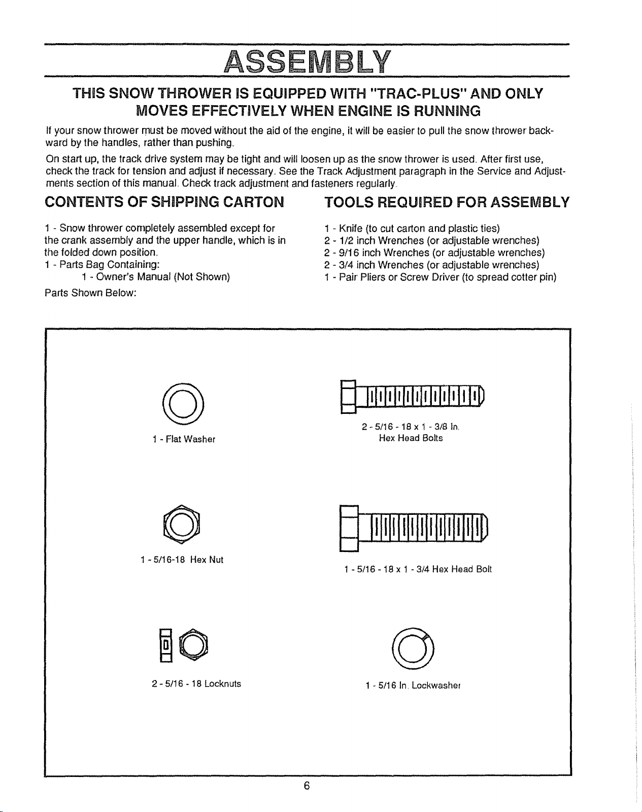
CONTENTS OF SHIPPING CARTON TOOLS REQUnRED FOR ASSEMBLY
1 - Snow thrower completely assembled except for
the crank assembly and the upper handle, which is in
the folded down position°
1 - Parts Bag Containing:
1 - Owner's Manual (Not Shown)
Parts Shown Below:
G
I - Fiat Washer
1 - Knife (to cut carton and plastic ties)
2 - 1/2 inch Wrenches (or adjustable wrenches)
2 - 9/16 inch Wrenches (or adjustable wrenches)
2 - 3/4 inch Wrenches (or adjustable wrenches)
t - Pair' Pliers or Screw Driver (to spread cotter pin)
iiIili!iIiiiIflmlilq_
2- 5/16- 18 x 1 - 3/8 In.
Hex Head Bolts
O
1 -5/16-18 Hex Nut
2 -5/! 6 - 18 Locknuts
O
1 - 5/16 In. Lockwasher
ASS L¥
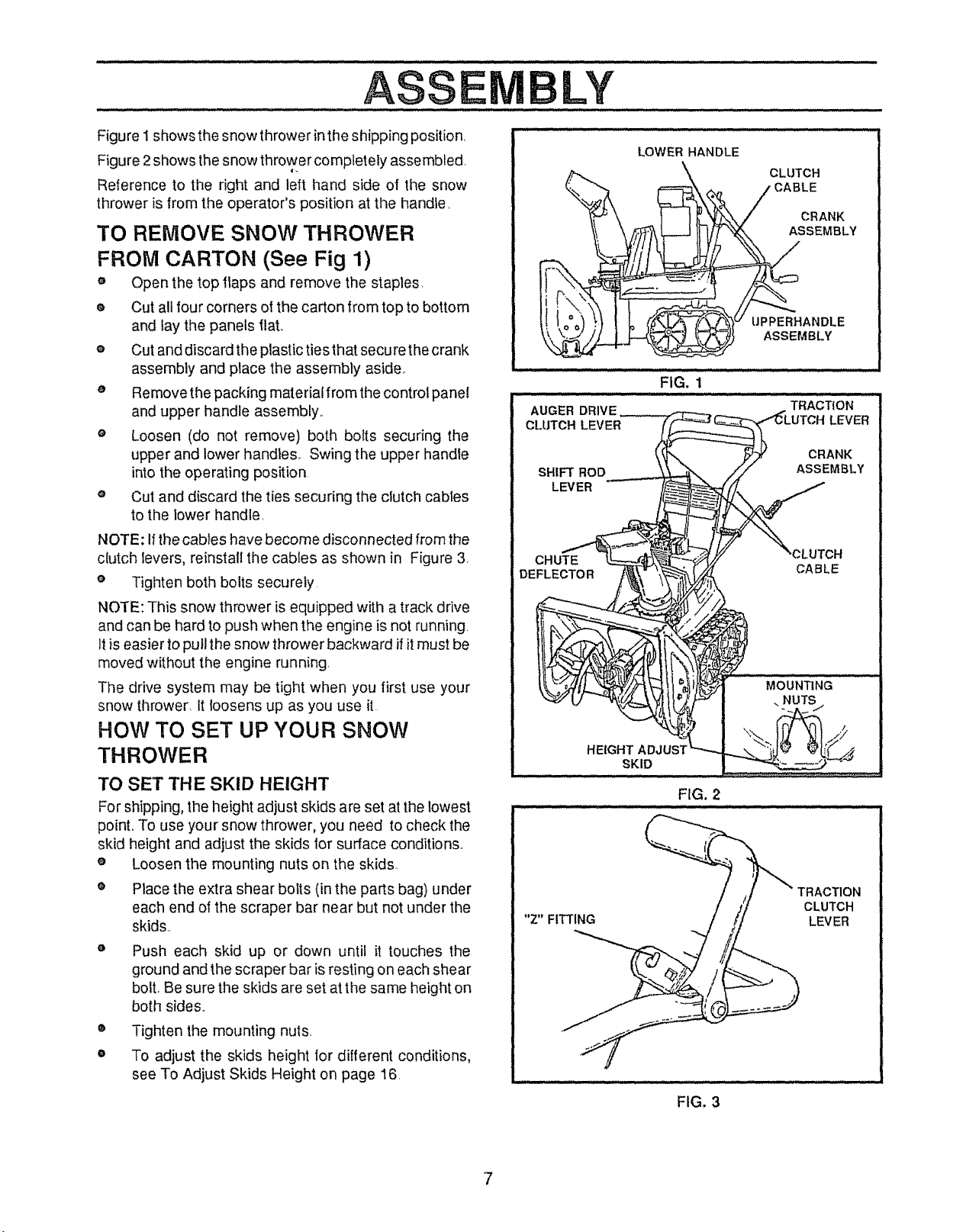
Figure I shows the snow thrower in the shipping position.
Figure 2 shows the snow thrower completely assembled,
Reference to the right and left hand side of the snow
thrower is from the operator's position at the hand_e,
TO REMOVE SNOW THROWER
FROM CARTON (See Fig 1)
e Open the top flaps and remove the staples
® Cut all four corners of the carton from top to bottom
and lay the panels flat.
o Cut and discard the plastic ties that secure the crank
assembly and place the assembly aside_
o Remove the packing material from the control panel
and upper handle assembly,,
o Loosen (do not remove) both bolts securing the
upper and lower handles,, Swing the upper handle
into the operating position,
e Cut and discard the ties securing the clutch cables
to the lower handle.
NOTE: Ifthe cables have become disconnected from the
clutch levers, reinstall the cables as shown in Figure 3,
o Tighten both bolts securely,
NOTE: This snow thrower is equipped with a track drive
and can be hard to push when the engine is not running.
It is easier to pull the snow thrower backward if it must be
moved without the engine running,
The drive system may be tight when you first use your
snow thrower, It loosens up as you use it
HOW TO SET UP YOUR SNOW
THROWER
LOWER HANDLE
CLUTCH
CABLE
CRANK
ASSEMBLY
UPPERHANDLE
ASSEMBLY
FIG. 1
TO SET THE SKID HEIGHT
For shipping, the height adjust skids are set at the lowest
point. To use your snow thrower, you need to check the
skid height and adjust the skids for surface conditions,
e Loosen the mounting nuts on the skids.,
o Place the extra shear bolts (in the parts bag) under
each end of the scraper bar near but not under the
skids.,
Push each skid up or down until it touches the
ground and the scraper bar is resting on each shear
bolt, Be sure the skids are set at the same height on
both sides,,
o
Tighten the mounting nuts.
o
To adjust the skids height for different conditions,
see To Adjust Skids Height on page 16,
7
"Z" FITTING
FIG, 2
TRACTION
CLUTCH
LEVER
FIG. 3
CAUTION: IF YOU ARE REMOVING
,_ SNOW FROM ANY ROCKY OR UNEVEN
SURFACES, RAISE THE FRONT OF THE
SNOW THROWER BY MOVING THE
SKIDS DOWN. THIS WILL HELP TO PREVENT
ROCKS AND OTHER DEBRIS FROM BEING
PICKED UP AND THROWN BY THE AUGER.
LY
IIIllUIIlllILillllllllllllllIll _IIIllU I II J
RIGHT
illlll ill iilll i_ IHlll ill_l Hj i_ I I
LEFT ADJUST NUTS
TO MOVE EYE
BOLT IN OR
OUT
BOOT'
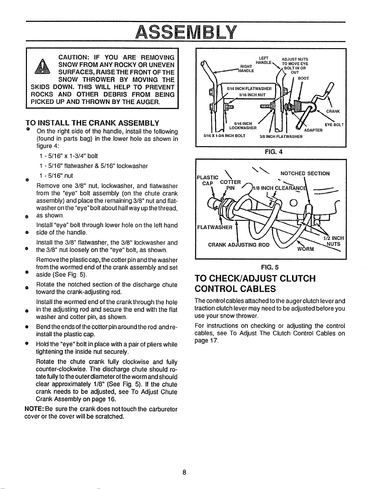
TO INSTALL THE CRANK ASSEMBLY
e On the right side of the handle, install the following
(found in parts bag) in the lower hote as shown in
figure 4:
1 - 5/16" x 1-3/4" bolt
1 - 5/16" flatwasher & 5/16" Iockwasher
1 - 5/16" nut
o
Remove one 3/8" nut, lockwasher, and flatwasher
from the "eye" bolt assembly (on the chute crank
assembly) and place the remaining 3/8" nut and flat-
washer on the "eye" bott about half way up the thread,
as shown
o
Install "eye" bolt through lower hole on the left hand
o
side of the handle.
install the 3/8" flatwasher, the 3/8" lockwasher and
o
the 3/8" nut loosely on the "eye" bolt, as shown_
Remove the plastic cap, the cotter pin and the washer
from the wormed end of the crank assembly and set
® aside (See Fig. 5).
Rotate the notched section of the discharge chute
o
toward the crank-adjusting rod_
Install the wormed end of the crank through the hole
e in the adjusting rod and secure the end with the flat
washer and cotter pin, as shown.
• Bend the ends of the cotter pin around the rod and re-
install the plastic cap.
o Hold the "eye" bolt in place with a pair of pliers while
tightening the inside nut securely.
Rotate the chute crank fully clockwise and fully
counter-clockwise. The discharge chute should ro-
tate fully to the outer diameteroi the worm and should
clear approximately 1/8" (See Fig 5)° If the chute
crank needs to be adjusted, see To Adjust Chute
Crank Assembly on page 16.
NOTE: Be sure the crank does nottouch the carburetor
cover or the cover will be scratched.
51t6 INCH
LOCKWASHEB
5116 X 1-314 INCH BOLT
ADAPTER
3/8 INCH FLATWASHER
w_ NK
EYE BOLT
FIG. 4
NOTCHED SECTION
CAP COTTER
FLATWASHER
I/2 INCH
CRANK ADJUSTING ROD
WORM
illlllllllllllllllll
FIG. 5
TO CHECK/ADJUST CLUTCH
CONTROL CABLES
The control cables attached to the auger clutch lever and
traction clutch lever may need to be adjusted before you
use your snow thrower.
For instructions on checking or adjusting the control
cables, see To Adjust The Clutch Control Cables on
page 17.
OPE AT O
:: .... : : :.
KNOW YOUR SNOW THROWER,
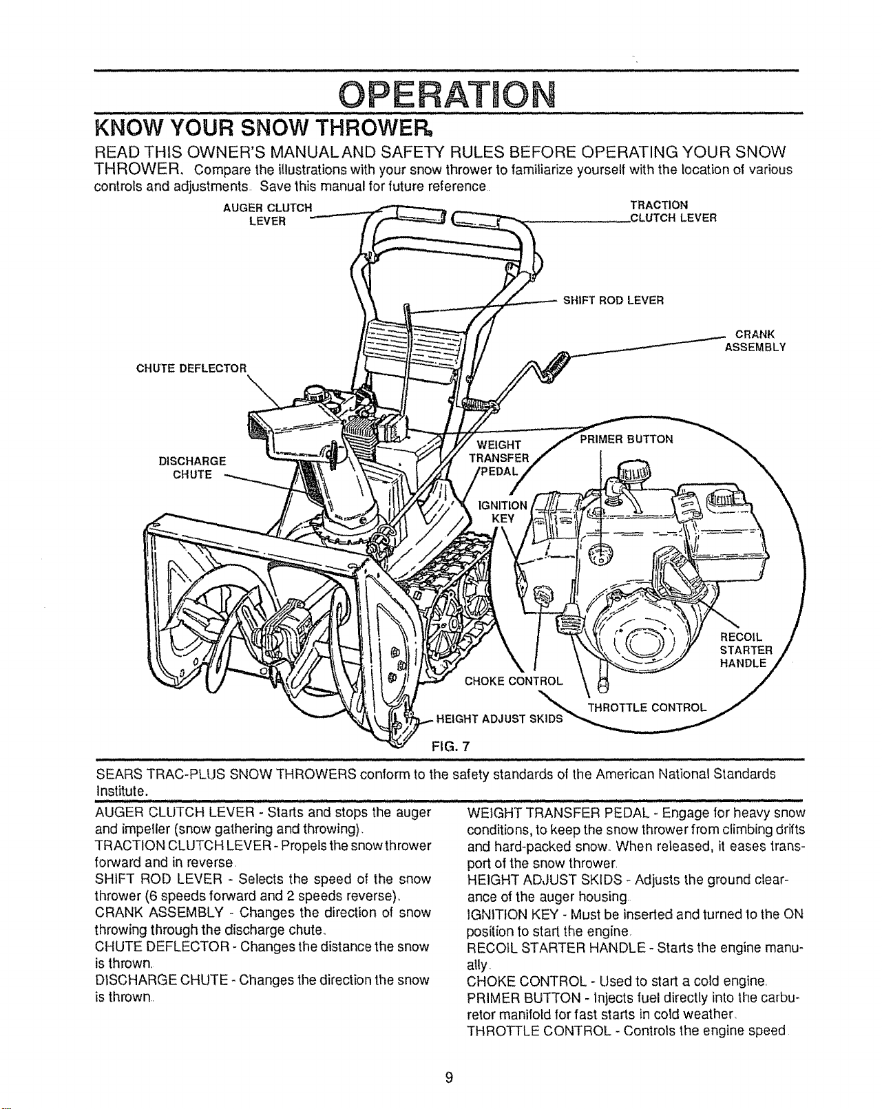
READ THIS OWNER'S MANUALAND SAFETY RULES BEFORE OPERATING YOUR SNOW
THROWER. Compare the illustrationswith your snow thrower to familiarize yourself with the location oi various
controls and adjustments. Save this manual for future reference
AUGER CLUTCH TRACTION
LEVER .CLUTCHLEVER
SHIFT ROD LEVER
CRANK
ASSEMBLY
CHUTE DEFLECTOR
BUTTON
RECOIL
STARTER
HANDLE
THROTTLE CONTROL
DISCHARGE
CHUTE
WEIGHT
TRANSFER
IGNITION
KEY
CHOKE CONTROL
HEIGHT ADJUST
FIG. 7
SEARS TRAC-PLUS SNOW THROWERS conform to the safety standards of the American National Standards
institute,
AUGER CLUTCH LEVER - Starts and stops the auger WEIGHT TRANSFER PEDAL - Engage for heavy snow
and impeller (snow gathering and throwing), conditions, to keep the snow thrower from climbing drifts
TRACTION CLUTCH LEVER-Propels the snow thrower and hard-packed snow,, When released, it eases trans-
forward and in reverse,
SHIFT ROD LEVER - Selects the speed of the snow
thrower (6 speeds forward and 2 speeds reverse),
CRANK ASSEMBLY - Changes the direction of snow
throwing through the discharge chute.,
CHUTE DEFLECTOR - Changes the distance the snow
is thrown,
DISCHARGE CHUTE - Changes the direction the snow
is thrown..
port of the snow thrower,
HEIGHT ADJUST SKIDS - Adjusts the ground clear-
ance of the auger housing.
IGNITION KEY - Must be inseded and turned to the ON
position to start the engine,
RECOIL STARTER HANDLE - Starts the engine manu-
ally.
CHOKE CONTROL - Used to start a cold engine,
PRIMER BUTTON - injects fuel directly into the carbu-
retor manifold for fast starts in cold weather,
THROTTLE CONTROL - Controls the engine speed
9
OPE A=f O
The operation of any snow th rower can result in foreign objects being thrown into the
eyes, which can result in severe eye damage_ Always wear safety glasses or eye
shields while operating the snow thrower.
We recommend standard safety glasses or Wide Vision Safety Mask for over your
glasses available at SEARS Retail or Catalog Stores.
HOW TO USE YOUR SNOW
THROWER
TO
CONTROL SNOW DISCHARGE
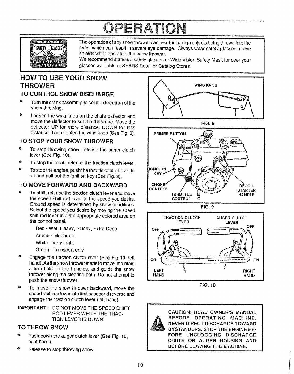
O
Turn the crank assembly to set the direction of the
snow throwing_
e Loosen the wing knob on the chute deflector and
move the deflector to set the distance° Move the
deflector UP for more distance, DOWN for less
distance. Then tighten the wing knob (See Fig 8)
TO STOP YOUR SNOW THROWER
• To stop throwing snow, release the auger clutch
lever (See Fig 10)_
e To stop the track, release the traction clutch tever
e To stop the engine, push the throttle control lever to
off and pull out the ignition key (See Fig 9)
TO
MOVE FORWARD AND BACKWARD
O
To shift, release the traction clutch lever and move
the speed shift rod lever to the speed you desire.
Ground speed is determined by snow conditions.
Select the speed you desire by moving the speed
shift rod lever into the appropriate colored area on
the control panel
Red - Wet, Heavy, Slushy, Extra Deep
Amber- Moderate
White - Very Light
Green - Transport only
o
Engage the traction clutch lever (See Fig 10, tett
hand) As the snowthrower starts to move, maintain
a firm hold on the handles, and guide the snow
thrower along the clearing path Do not attempt to
push the snow thrower.
To move the snow thrower backward, move the
speed shift rod lever into first or second reverse and
engage the traction clutch lever (left hand).
IMPORTANT:
TO THROW SNOW
Push down the auger clutch lever (See Fig. 10,
right hand).
Release to stop throwing snow
DO NOT MOVE THE SPEED SHIFT
ROD LEVER WHJLE THE TRAC-
TION LEVER IS DOWN
FIG. 8
PRIMER BUTTON
IGNITION
KEY
CHOKE'
CONTROL
THROTTLE
CONTROL
STARTER
HANDLE
FIGo9
IU,HI, I:l / / I I I I
TRACTION CLUTCH AUGER CLUTCH
LEVER LEVER
/
HAND HAND
FIG. 10
CAUTION: READ OWNER'S MANUAL
BEFORE OPERATING MACHINE,
NEVER DIRECT DISCHARGE TOWARD
BYSTANDERS. STOP THE ENGINE BE-
FORE UNCLOGGING DISCHARGE
CHUTE OR AUGER HOUSING AND
BEFORE LEAVING THE MACHINE.
,, Ill
li,,HUll m
OFF
RIGHT
=lUl
10
OPERATION
TO USE WEIGHT TRANSFER SYSTEM ...................... ..............................
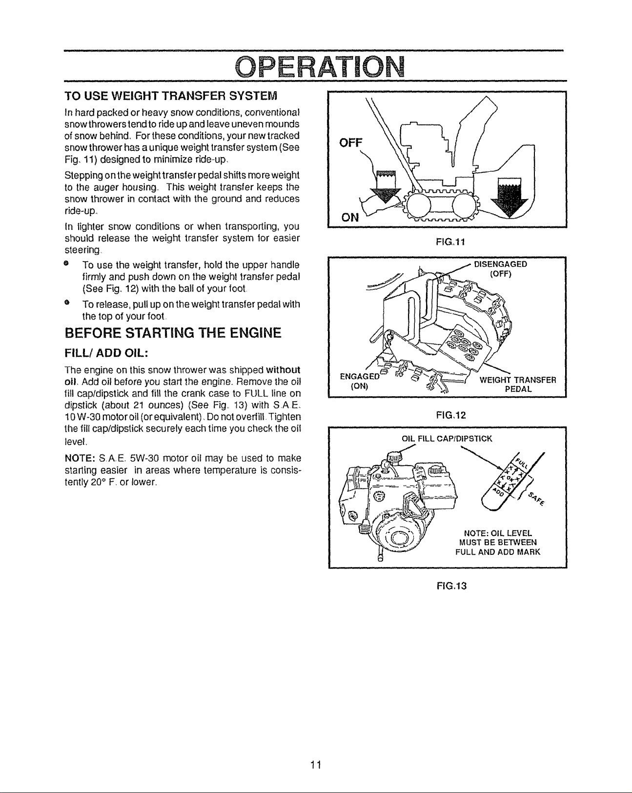
In hard packed or heavy snow conditions, conventional
snow throwers tend to ride up and leave uneven mounds
of snow behind. For these conditions, your new tracked
snow thrower has a unique weight transfer system (See
Fig, 11) designed to minimize ride-up,
Stepping on the weight transfer pedal shiit s more weight
to the auger housing. This weight transfer keeps the
snow thrower in contact with the ground and reduces
ride-up.
In Iighter snow conditions or when transporting, you
should release the weight transfer system 1or easier
steering.
e To use the weight transfer, hold the upper handle
firmly and push down on the weight transfer pedal
(See Fig_12) with the ball of your foot.
e To release, pull up on the weight transfer pedal with
the top of your foot.
BEFORE STARTING THE ENGtNE
OFF
ON
FIGol I
FILL! ADD OIL:
The engine on this snow thrower was shipped without
oil, Add oil before you start the engine.. Remove the oil
fill cap/dipstick and fill the crank case to FULL line on
dipstick (about 21 ounces) (See Fig.. 13) with S.AE.
10 W-30 motor oil (or equivalent). Do not overfill. Tighten
the fill cap/dipstick securely each time you check the oil
level,,
NOTE: SAE. 5W-30 motor oil may be used to make
starting easier in areas where temperature is consis-
tently 20° F, or lower..
ENGAG_ /
(ON)
FIG,12
11,, ....H J , ,iJ ,, , j=,i i ....
OIL FILL CAPtDIPSTICK
NOTE: OIL LEVEL
MUST BE BETWEEN
FULL AND ADD MARK
FIG,13
WEIGHT TRANSFER
PEDAL
il
,H,I i i ..........
OPE
FILL GAS:
Fill the fuel tank with clean, fresh, unleaded grade auto-
motive gasoline., Be sure that the container you pour the
gasoline from is clean and free from rust or other foreign
particles.. Never use gasoline that may be stale from long
periods of storage in the container°
WARNING: Experience indicates that alcohol blended
fuels (called gasohol or' using ethanol or methanol) can
attract moisture which leads to separation and formation
of acids during storage.. Acidic gas can damage the fuel
system of an engine while in storage,
To avoid engine problems, the fuel system should be
emptied before storage for 30 days or longer'.. Drain the
gas tank, start the engine and let it run until the fuet lines
and carburetor are empty.. Use the carburetor bowl drain
to empty residual gasoline from the float chamber
(Figure 39).. Use fresh fuel next season.. (See Storage
instructions on page 23 for additional information..)
Never use engine or carburetor cleaner products in the
fuel tank or permanent damage may occur.
_ AUTION: GASOLINE IS FLAMMABLE
DO NOT FILL FUEL TANK WHILE SNOW
THROWER iS RUNNING,WHEN IT IS HOT, OR
WHEN SNOW THROWER IS tN AN ENCLOSED
AREA.
KEEP AWAY FROM OPEN FLAME OR AN ELEC-
TRICAL SPARK AND DO NOT SMOKE WHILE
FILLING THE FUEL TANK.
NEVER FILL THE TANK COMPLETELY. FILL
TH E TANK TO WITHIN 1/4"- 1/2" FROM TH E TOP
TO PROVIDE SPACE FOR EXPANSION OF FUEL.
ALWAYS FILL FUEL TANK OUTDOORS AND
USE A FUNNEL OR SPOUTTO PREVENTSPILL-
ING.
MAKE SURE TO WIPE UP ANY SPILLED FUEL
BEFORE STARTING THE ENGINE.
STORE GASOLINE IN A CLEAN, APPROVED
CONTAINER AND KEEP THE CAP IN PLACE ON
THE CONTAINER°
AND CAUTION MUST BE USED WHEN
HANDLING OR STORING IT.
ATIO
CAUTION: NEVER RUN ENGINE IN-
DOORS OR IN ENCLOSED, POORLY
VENTILATED AREAS. ENGINE EX-
HAUST CONTAINS CARBON MON-
OXIDE, AN ODORLESS AND DEADLY GAS.
KEEP HANDS, FEET, HAIR AND LOOSE CLOTH-
ING AWAY FROM ANY MOVING PARTS ON
ENGINE AND SNOW THROWER=
WARNING: TEMPERATURE OF MUFFLER AND
NEARBY AREAS MAY EXCEED 150° F. AVOID
THESE AREAS.
DO NOT ALLOW CHILDREN OR YOUNG TEEN-
AGERS TO OPERATE OR BE NEAR SNOW
THROWER WHILE IT IS OPERATING.
TO STOP ENGmNE
e To stop engine, move the throttle control lever to
"STOP" position and remove key. Keep the key in a
safe place_ The engine will not start without the key.
TO START ENGINE
Be sure that the engine has sufficient oil. Before starting
the engine, be certain that you have read the following
information:
COLD START (See Fig. 14)
O
Be sure the auger and the traction clutch levers are
in the disengaged "RELEASED" position.
® Move the throttle control up to "FAST" position.
® Push the key into the ignition slot. Be sure it snaps
into place, Do not turn key.
o
Rotate choke control to "FULL" choke position,
o
Press the primer button two or three times, while
keeping your finger' over the vent hole on the primer
button. Additional priming may be necessary for the
first start if the temperature is below 15° F,
o
Pull the starter handle rapidly, Do not allow the
handle to snap back, but allow it to rewind slowly
while keeping a firm hold on the starter handle.
As the engine warms up and begins to operate
evenly, rotate the choke knob slowly to "OFF" posi-
tion. If the engine falters, return to "FULL" choke,
then slowly move to "OFF" choke position.
NOTE: Allow the engine to warm up for a few minutes
because the engine will not develop full power until it
reaches operating ternperature.
e Run the engine at or near the top speed when
throwing snow..
12
 Loading...