

Craftsman 536885201 Owner’s Manual
Operator's Manual
Snow Thrower
3.8 Horsepower 4-Cycle Engine
21-inch Single Stage
Auger Propelled
Model536.885201
CAUTION: Before using this product,
read this manual and follow all of its
Safety Rules and Operating Instructions.
CRRFTSMRN °
Manual del usario
Quitanieves
de 21 pulgadas
3.8 caballos de fuerza (hp)
Monoetapico
Propulsado por barrena
Modelo 536.885201
PRECAUCION: Antes de usar este producto,
lea este manual y siga todas las reglas de
seguridad e instrucciones de operaci6n.
Sears, Roebuck and Co., Hoffman Estates, IL 60179 U.S.A.
F-011060M www.sears.com/craftsman
NnIL,'q:] ! =l(o]j[_o] _Innl=1_In_
WARRANTY STATEMENT ......
SAFETY RULES ...............
INTERNATIONAL SYMBOLS . ..
ASSEMBLY ...................
OPERATION ..................
MAINTENANCE ...............
SERVICE AND ADJUSTMENT ..
LIMITED ONE-YEAR WARRANTY ON CRAFTSMAN SNOW THROWER
For one years from the date of purchase, when this Craftsman Snow thrower is maintained,
lubricated, and tuned up according to the operating and maintenance instructions in the
owner's manual, Sears will repair, free of charge, any defect in material or workmanship.
If this Craftsman Snow thrower is used for commercial or rental purposes, this warranty ap-
plies for only 90 days from the date of purchase.
This warranty does not cover the following:
Items which become worn during normal use, such as spark plugs, drive belts and shear
pins.
Repair necessary because of operator abuse or negligence, including bent crankshafts
and the failure to maintain the equipment according to the instructions contained in the
owner's manual.
WARRANTY SERVICE IS AVAILABLE BY RETURNING THE CRAFTSMAN SNOW
THROWER TO THE NEAREST SEARS SERVICE CENTER/DEPARTMENT IN THE
UNITED STATES. THIS WARRANTY APPLIES ONLY WHILE THIS PRODUCT IS IN USE
IN THE UNITED STATES.
This warranty gives you specific legal rights, and you may also have other rights which may
vary from state to state.
Sears, Roebuck and Co., D817WA, Hoffman Estates. IL 60179
2 STORAGE .................... 23
3 TROUBLE SHOOTING CHART.. 24
5 REPAIR PARTS ............... 28
7 ENGINE REPAIR PARTS ....... 34
9 SPANISH (ESPAI_IOL) .......... 40
15 PARTS ORDERING/SERVICE ..
18 BACK COVER
GENERAL RECOMMENDATIONS
The warranty on this snow thrower does
not cover items that have been sub-
jected to operator abuse or negligence.
To receive full value from the warranty,
the operator must maintain the snow
thrower as instructed in this manual.
Some adjustments will need to be made
periodically to properly maintain your
snow thrower.
All adjustments in the Service and Ad-
justments section of this manual must
be checked at least once each season.
F-011060M
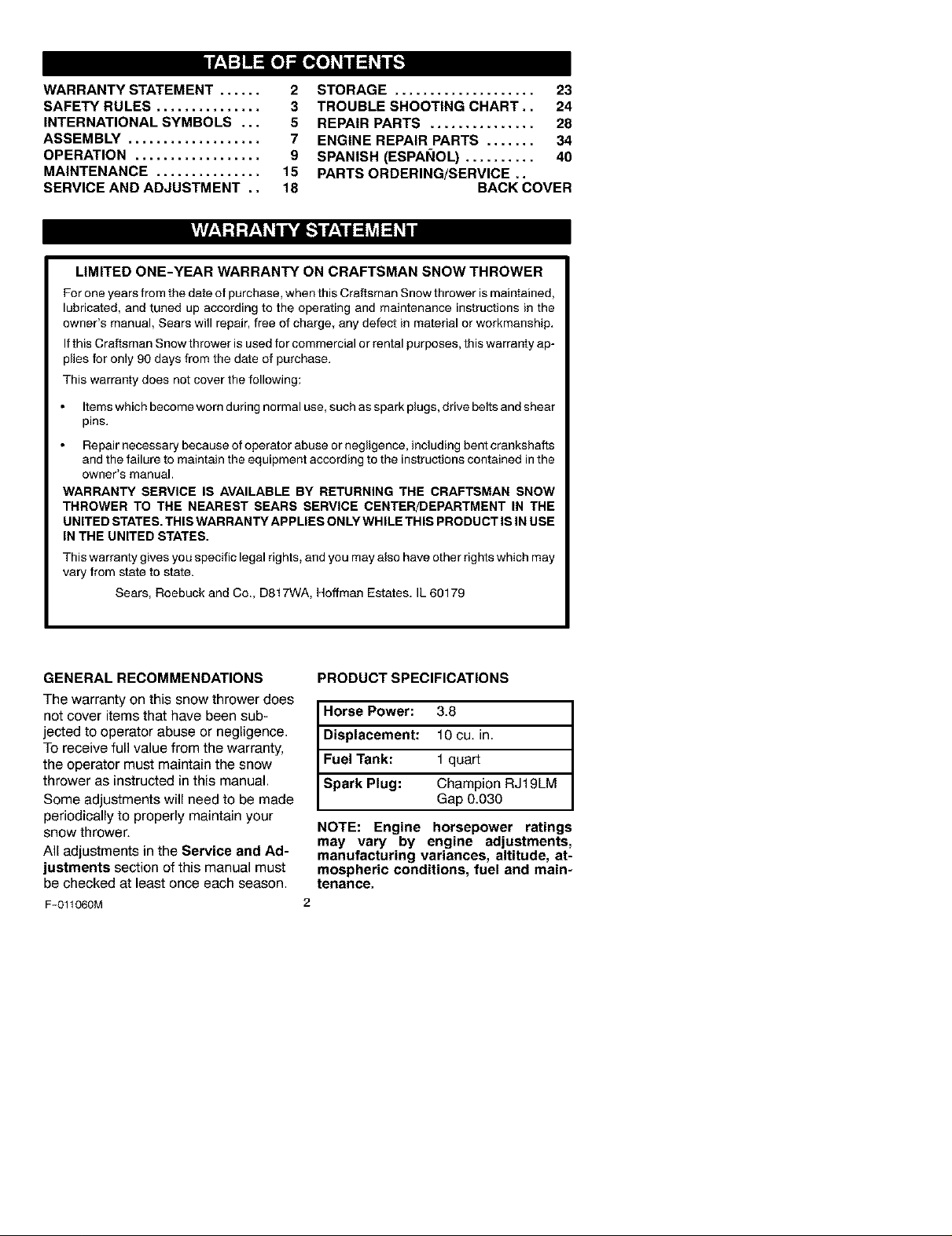
PRODUCT SPECIFICATIONS
Horse Power: 3.8
Displacement: 10 cu. in.
Fuel Tank: 1 quart
Champion RJf 9LM
Spark Plug: Gap 0.030
NOTE: Engine horsepower ratings
may vary by engine adjustments,
manufacturing variances, altitude, at-
mospheric conditions, fuel and main-
tenance.
_lk OOK FOR THIS SYMBOL TO POINT OUT IMPORTANT SAFETY PRECAUTIONS.
d_lb WARNING: Always disconnect
with spark plug to prevent accidental
starting during: Preparation, Mainte-
nance, or Storage of you snow thrower.
IMPORTANT: Safety standards require oper=
ator presence controls to minimize the risk of in-
jury. Your snow thrower isequipped with such
controls. Do not attempt to defeat the function
of the operator presence control under any cir-
cumstances.
TRAINING
1. Read the operating and service instruction
2. Never allow children to operate the equip=
3. Keep the area of operation clear of all per-
4. Exercise caution to avoid slipping or falling
PREPARATION
1. Thoroughly inspect the area where the
F-011060M
IT MEANS-- ATTENTION!!! BECOME ALERT!!! YOUR SAFETY IS INVOLVED.
2. Disengage all cIu[ches before starting the
engine (motor).
3. Do not operate the equipment without
Engine Exhaust, some of its con-
stituents, and certain vehicle com-
ponents contain or emit chemicals
known to the State of California to
cause cancer and birth defects or
other reproductive harm.
Battery posts, terminals and re-
lated accessories contain lead
and lead compounds, chemicals
known to the State of California to
cause cancer and birth defects or
other reproductive harm. WASH
HANDS AFTER HANDLING.
the spark plug wire and place it
where it cannot make contact
manual carefully. Be thoroughly familiar
with the controls and the proper use of the
equipment. Know how to stop the unit and
disengage the controls quickly.
merit. Never allow adults to operate the
equipment without proper instruction.
sons, particularly small children and pets.
especially when operating in reverse.
equipment is to be used and remove all
doormats, sleds, boards, wires, and other
foreign objects.
wearing adequate winter outer garments.
Wear footwear that will improve footing on
slippery surfaces.
4. Handle fuel with care; it is highly flam-
mable.
a. Use an approved fuel container.
b. Never remove fuel tank cap or add fuel
to a running engine (motor) or hot en-
gine (motor).
c. Fill fuel tank outdoors with extreme
care. Never fill fuel tank indoors.
d. RepIace fuel cap securely and wipe up
spilled fuel.
Never store fuel or snow thrower with
fuel in the tank inside of a building
where fumes may reach an open flame
or spark.
f. Check fuel supply before each use, al-
lowing space for expansion as the heat
of the engine (motor) and/or sun can
cause fuel to expand.
5. For all units with electdc starting motors
use electric starting extension cords certi-
fied CSA!UL. Use only with a receptacle
that has been installed in accordance with
local inspection authodties.
6. Never attempt to make any adjustments
while the engine (motor) is running (except
when specifically recommended by manu-
facturer).
7. Let engine (motor) and snow thrower ad-
justto outdoor temperatures before starting
to clear snow.
8. Always wear safety glasses or eye shields
during operation or while performing an ad-
justment or repair to protect eyes from
foreign objects that may be thrown from the
snow thrower.
OPERATION
1. Do not operate this machine if you are tak-
ing drugs or other medication which can
cause drowsiness or affect your ability to
operate this machine,
2. Do not use this machine ifyou are mentally
or physically unable to operate this ma-
chine safely.
3. Donotputhandsorfeetnearorunderro-
14.Donotoverloadthemachinecapacityby
tatingparts.Keepclearofthedischarge
openingatalltimes.
15.Neveroperatethemachineathightrans-
4. Exerciseextremecautionwhenoperating
onorcrossinggraveldrives,walksor
roads.Stayalertforhiddenhazardsor
traffic.
5. Afterstrikingaforeignobject,stoptheen-
gine(motor),removethewirefromthe
16.Neverdirectdischargeatbystandersor
17.Disengagepowertothecollector/impeller
sparkplug,thoroughlyinspectsnow
throwerforanydamage,andrepairthe
damagebeforerestartingandoperating
thesnowthrower.
6. Iftheunitshouldstarttovibrateabnormal-
Iy,stoptheengine(motor)andcheckim-
18.Useonlyattachmentsandaccessoriesap-
19.Neveroperatethesnowthrowerwithout
mediatelyforthecause.Vibrationis
generallyawarningoftrouble.
7. Stoptheengine(motor}wheneveryou
leavetheoperatingposition,beforeun-
cloggingtheauger/impellerhousingordis-
chargechuteandwhenmakingany
repairs,adjustments,orinspections.
8. Whencleaning,repairing,orinspecting,
makecertaintheauger/impellerandall
20.Donotover-reach.Keepproperfooting
21.Donotattempttousesnowthrowerona
MAINTENANCE AND STORAGE
1. Check bolts at frequent intervals for proper
movingpartshavestoppedandallcontrols
aredisengaged.Disconnectthesparkplug
wireandkeepthewireawayfromthespark
2. Never store the snow thrower with fuel in
plugtopreventaccidentalstarting.
9. Takeallpossibleprecautionswhenleaving
thesnowthrowerunattended.Disengage
theauger/impellerandstoptheengine
(motor).
10.Donotruntheengine(motor)indoors,ex-
3. Always refer to operator's guide instruc-
ceptwhenstartingtheengine(motor)and
fortransportingthesnowthrowerinorout
ofthebuilding.Opentheoutsidedoors;ex-
haustfumesaredangerous(containing
CARSONMONOXIDE,anODORLESS
andDEADLYGAS).
11.Donotclearsnowacrossthefaceof
4. Maintain or replace safety and instruction
5. Run the snow thrower a few minutes after
slopes.Exerciseextremecautionwhen
changingdirectiononslopes.Donotat-
tempttoclearsteepslopes.
12.Neveroperatethesnowthrowerwithout
properguards,platesorothersafetypro-
tectivedevicesinplace.
13.Neveroperatethesnowthrowernearen-
closures,automobiles,windowwells,
drop-offs,andthelikewithoutproperad-
justmentof thesnowdischargeangle.
Keepchildrenandpetsaway.
Caution should be exercised while using on
steep sloping surfaces. DO NOT USE
SNOW THROWER ON SURFACES ABOVE
GROUND LEVEL such as roofs of resi-
dences, garages, porches or other such
structures or buildings.
attemptingtoclearsnowattoofastarate.
portspeedsonslipperysurfaces.Lookbe-
hindandusecarewhenbackingup.
allowanyoneinfrontoftheunit.
whensnowthroweristransportedornotin
use,
provedbytheman_acturerofthesnow
thrower.
goodvisibilityorlight.Alwaysbesureof
yourfootingandkeepafirmholdonthe
handles.Walk;neverrun.
andbalanceata]Itimes.
roof.
tightness to be sure the equipment is in
safe working condition.
the tank inside a building where ignition
sources are present such as hot water and
space heaters, clothes dryers, and the like.
Allow the engine (motor) to cool before
storing in any enclosure.
tions for important details if the snow
thrower is to be stored for an extended
period.
labels, as necessary.
throwing snow to prevent freeze-up of the
auger/impeller.
for use on sidewalks, driveways
_IL WARNING: This snow thrower is
and other ground level surfaces.
F-011060M 4
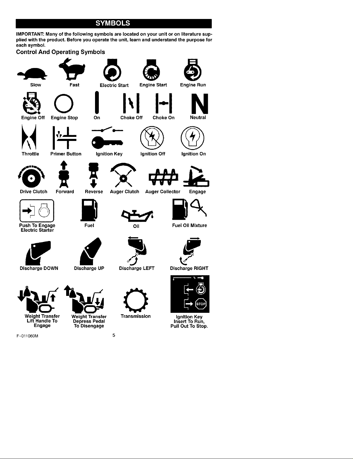
IMPORTANT: Many of the following symbols are located on your unit or on literature sup-
plied with the product. Before you operate the unit, learn and understand the purpose for
each symbol.
Control And Operating Symbols
Slow Fast Electric Start Engine Start Engine Run
H N
Engine Off Engine Stop On Choke Off Choke On Neutral
®Q
Throttle Primer Button Ignition Key
Drive Clutch Forward Reverse Auger Clutch Auger Collector Engage
Push To Engage
Electric Starter
Fuel Oil Fuel Oil Mixture
Ignition Off Ignition On
f d
Discharge DOWN Discharge UP Discharge LEFT Discharge RIGHT
Weight Transfer Weight Transfer Transmission Ignition Key
Lift Handle To Depress Pedal Insert To Run,
Engage To Disengage Pull Out To Stop.
F-O11060M 5
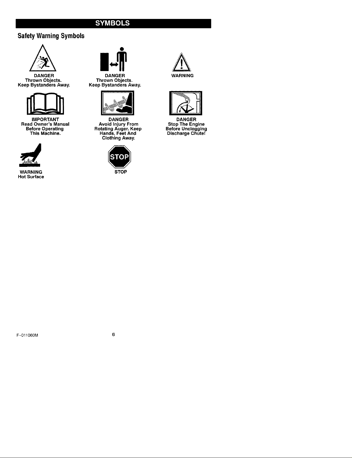
Safety WarningSymbols
DANGER
Thrown Objects.
Keep Bystanders Away.
IMPORTANT
Read Owner's Manual
Before Operating
This Machine.
WARNING
Hot Surface
DANGER
Thrown Objects.
Keep Bystanders Away.
DANGER
Avoid Injury From
Rotating Auger. Keep
Hands, Feet And
Clothing Away.
STOP
WARNING
DANGER
Stop The Engine
Before Unclogging
Discharge Chute!
F-O11060M 6
Contents of Parts Bag (actual size)
1 - Owner's Manual (notshown)
1 - Packet of Fuel Stabilizer (not shown)
,_ WARNING: Always wearsafety glasses or eye shields
while assembling snow
thrower.
TOOLS REQUIRED
1 - Knife tocut carton
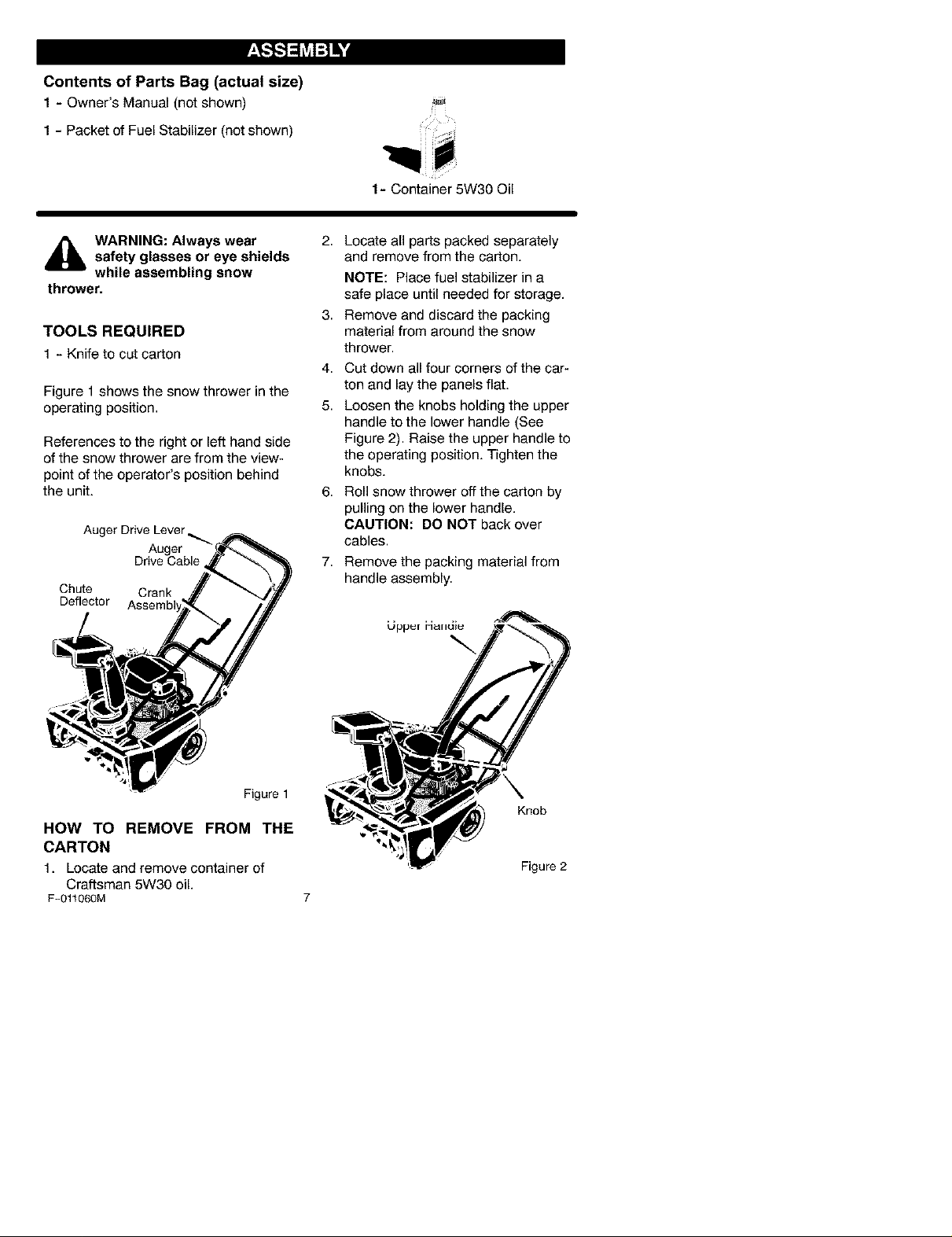
Figure 1 shows the snow thrower in the
operating position.
References to the right or left hand side
of the snow thrower are from the view-
point of the operator's position behind
the unit.
Auger Drive Lever _.
Chute Crank
Deflector
Auger
Drive Cable
1- Container 5W30 Oil
2,
Locate all parts packed separately
and remove from the carton.
NOTE: Place fuel stabilizer in a
safe place until needed for storage.
3,
Remove and discard the packing
material from around the snow
thrower.
4.
Cut down all four corners of the car-
ton and lay the panels flat.
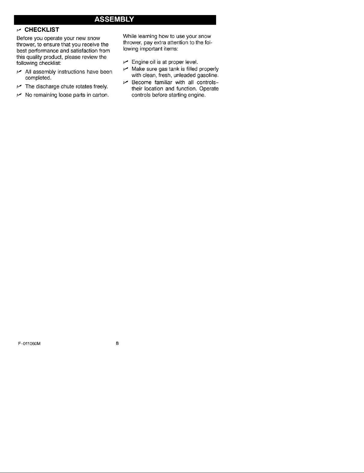
5.
Loosen the knobs holding the upper
handle to the lower handle (See
Figure 2). Raise the upper handle to
the operating position. Tighten the
knobs.
6,
Roll snow thrower off the carton by
pulling on the lower handle.
CAUTION: DO NOT back over
cables.
7,
Remove the packing material from
handle assembly.
Figure 1
HOW TO REMOVE FROM THE
CARTON
1. Locate and remove container of
Craftsman 5W30 oil.
F-011060M
Knob
Figure 2
_" CHECKLIST
Before you operate your new snow
thrower, to ensure that you receive the
best performance and satisfaction from
this quality product, please review the
following checklist:
_' All assembly instructions have been
completed.
_' The discharge chute rotates freely.
_' No remaining loose parts in carton.
While learning how to use your snow
thrower, pay extra attention to the fol-
lowing important items:
_' Engine oil is at proper level.
_' Make sure gas tank is filled properly
with clean, fresh, unleaded gasoline.
_' Become familiar with all controls-
their location and function. Operate
controls before starting engine.
F-011060M 8
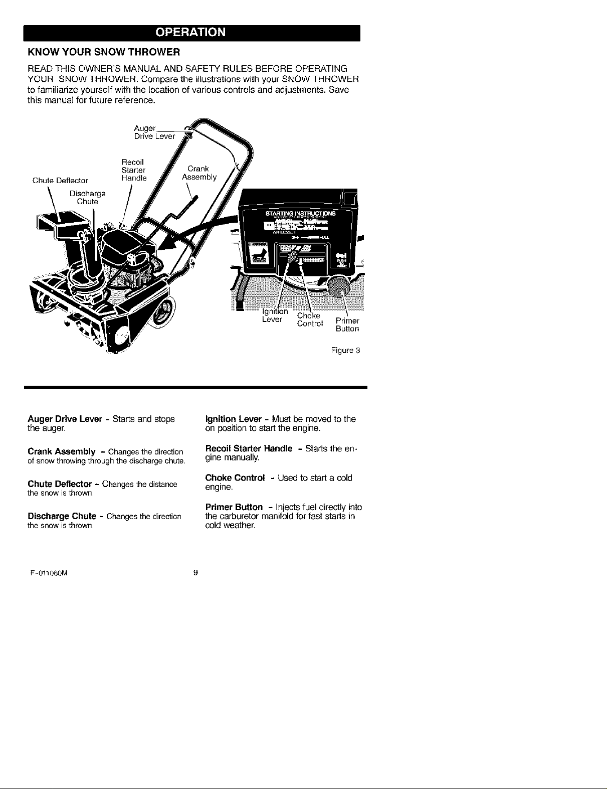
KNOW YOUR SNOW THROWER
READ THIS OWNER'S MANUAL AND SAFETY RULES BEFORE OPERATING
YOUR SNOW THROWER. Compare the illustrations with your SNOW THROWER
to familiarize yourself with the location of various controls and adjustments. Save
this manual for future reference.
Drive Lever
Recoil
Starter
Chute Deflector Handle
Discharge
Chute
Ignition
Lever Choke
Cont_I
Primer
Bu_on
Auger Drive Lever- Starts and stops
the auger.
Crank Assembly - Changesthe direction
of snowthrowingthroughthe dischargechLOe,
Chute Deflector - Changes thedistance
the snow isthrown.
Discharge Chute - Changesthe direction
the snow isthrown.
F-011060M 9
Figure 3
Ignition Lever - Must be moved to the
on position to start the engine.
RecoilStarter Handle - Startstheen-
gine manually.
Choke Control - Used to start a cold
engine.
Primer Button - Injects fuel directly into
the carburetor manifold for fast starts in
cold weather.
The operation of any snow thrower can
result in foreign objects being thrown
into the eyes, which can result in se-
vere eye damage. Always wear safety
glasses or eye shields while operating
the snow thrower.
We recommend standard safety
glasses or a wide vision safety mask for
over your glasses.
,_ WARNING: Read Owner's
Manual before operating
machine. Never direct dis-
charge toward bystanders stop the
engine before unclogging discharge
chute or auger housing and before
leaving the machine.
TO STOP YOUR
SNOW THROWER
1. To stop throwing snow, release the
auger drive lever. See Figure 3.
NOTE: If the snow thrower contin-
ues to slowly move forward, see
"How To Adjust The Auger Control
Cable" in the Service And Adjust-
ment Section.
2. To stop the engine, move the igni-
tion lever to the off position.
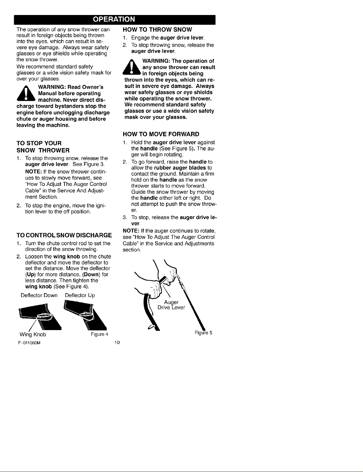
TO CONTROL SNOW DISCHARGE
1. Turn the chute control rod to set the
direction of the snow throwing.
2. Loosen the wing knob on the chute
deflector and move the deflector to
set the distance. Move the deflector
(Up) for more distance, (Down) for
less distance. Then tighten the
wing knob (See Figure 4).
Deflector Down Deflector Up
HOW TO THROW SNOW
1. Engage the auger drive lever.
2. To stop throwing snow, release the
auger drive lever.
,_ WARNING: The operation of
any snow thrower can result
in foreign objects being
thrown into the eyes, which can re-
sult in severe eye damage. Always
wear safety glasses or eye shields
while operating the snow thrower.
We recommend standard safety
glasses or use a wide vision safety
mask over your glasses.
HOW TO MOVE FORWARD
1,
Hold the auger drive lever against
the handle (See Figure 5). The au-
ger will begin rotating.
2.
To go forward, raise the handle to
allow the rubber auger blades to
contact the ground. Maintain a firm
hold on the handle as the snow
thrower starts to move forward.
Guide the snow thrower by moving
the handle either left or right. Do
not attempt to push the snow throw-
er.
3. To stop, release the auger drive le-
ver.
NOTE: If the auger continues to rotate,
see "How To Adjust The Auger Control
Cable" in the Service and Adjustments
section.
Wing Knob Figure 4
F-011060M 10
Figure 5
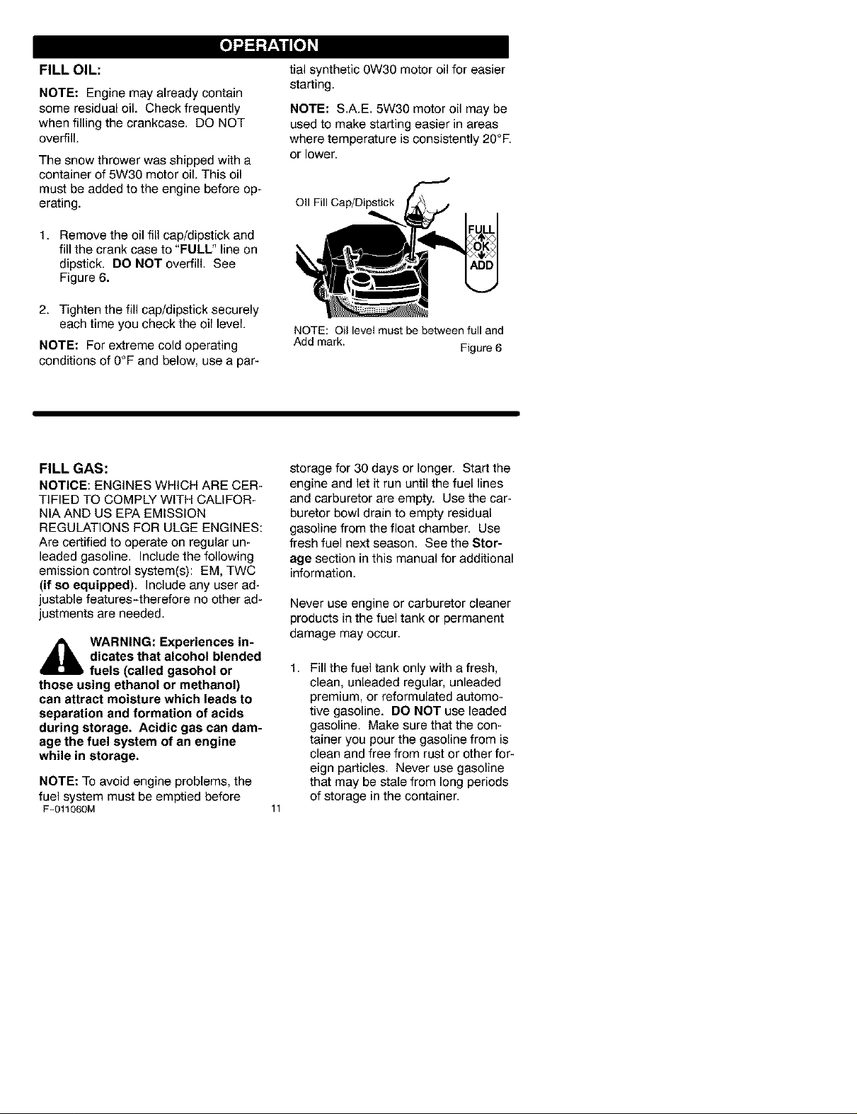
FILL OIL:
NOTE: Engine may already contain
some residual oil. Check frequently
when filling the crankcase. DO NOT
overfill.
The snow thrower was shipped with a
container of 5W30 motor oil. This oil
must be added to the engine before op-
erating.
1. Remove the oil fill cap/dipstick and
fill the crank case to "FULL" line on
dipstick. DO NOT overfill. See
Figure 6.
2. Tighten the fill cap/dipstick securely
each time you check the oil level.
NOTE: For extreme cold operating
conditions of 0°F and below, use a par-
tial synthetic 0W30 motor oil for easier
starting.
NOTE: S.A.E. 5W30 motor oil may be
used to make starting easier in areas
where temperature is consistently 20°E
or lower.
OII FillCap/Dipstick
NOTE: Oil level must be behNeen full and
Add mark.
Figure 6
FILL GAS:
NOTICE: ENGINES WHICH ARE CER-
TIFIED TO COMPLY WITH CALIFOR-
NIA AND US EPA EMISSION
REGULATIONS FOR ULGE ENGINES:
Are certified to operate on regular un-
leaded gasoline. Includethe following
emission control system(s): EM, TWC
(if so equipped). Include any user ad-
justable features-therefore no other ad-
justments are needed.
_lb WARNING: Experiences in-
dicates that alcohol blended
fuels (called gasohol or
those using ethanol or methanol)
can attract moisture which leads to
separation and formation of acids
during storage. Acidic gas can dam-
age the fuel system of an engine
while in storage.
NOTE: To avoid engine problems, the
fuel system must be emptied before
F-011060M
storage for 30 days or longer. Start the
engine and let it run until the fuel lines
and carburetor are empty. Use the car-
buretor bowl drain to empty residual
gasoline from the float chamber. Use
fresh fuel next season. See the Stor-
age section in this manual for additional
information.
Never use engine or carburetor cleaner
products in the fuel tank or permanent
damage may occur.
1,
Fill the fuel tank only with a fresh,
clean, unleaded regular, unleaded
premium, or reformulated automo-
tive gasoline. DO NOT use leaded
gasoline. Make sure that the con-
tainer you pour the gasoline from is
clean and free from rust or other for-
eign particles. Never use gasoline
that may be stale from long periods
of storage in the container.
11
_lb ARNING: Gasoline is flam-
gasoline.
Do not fill fuel tank while snow
thrower is running, when it is hot, or
when snow thrower is in an en-
closed area.
Keep away from open flame or an
electrical spark and do not smoke
while filling the fuel tank.
Never fill the tank completely. Fill
the tank to within 1/4"-1/2" from the
top to provide space for expansion
of fuel.
Always fill fuel tank outdoors and
use a funnel or spout to prevent
spilling.
Make sure to wipe up any spilled
fuel before stating the engine.
Store gasoline in a clean, approved
container and keep the cap in place
on the container.
mable. Always use caution
when handling or storing
BEFORE STARTING THE ENGINE
1. Before you service or start the en-
gine, familiarize yourself with the
snow thrower. Be sure you under-
stand the function and location of all
controls.
2. Be sure that all fasteners are tight.
3. Before starting the engine, make
sure all controls operate correctly.
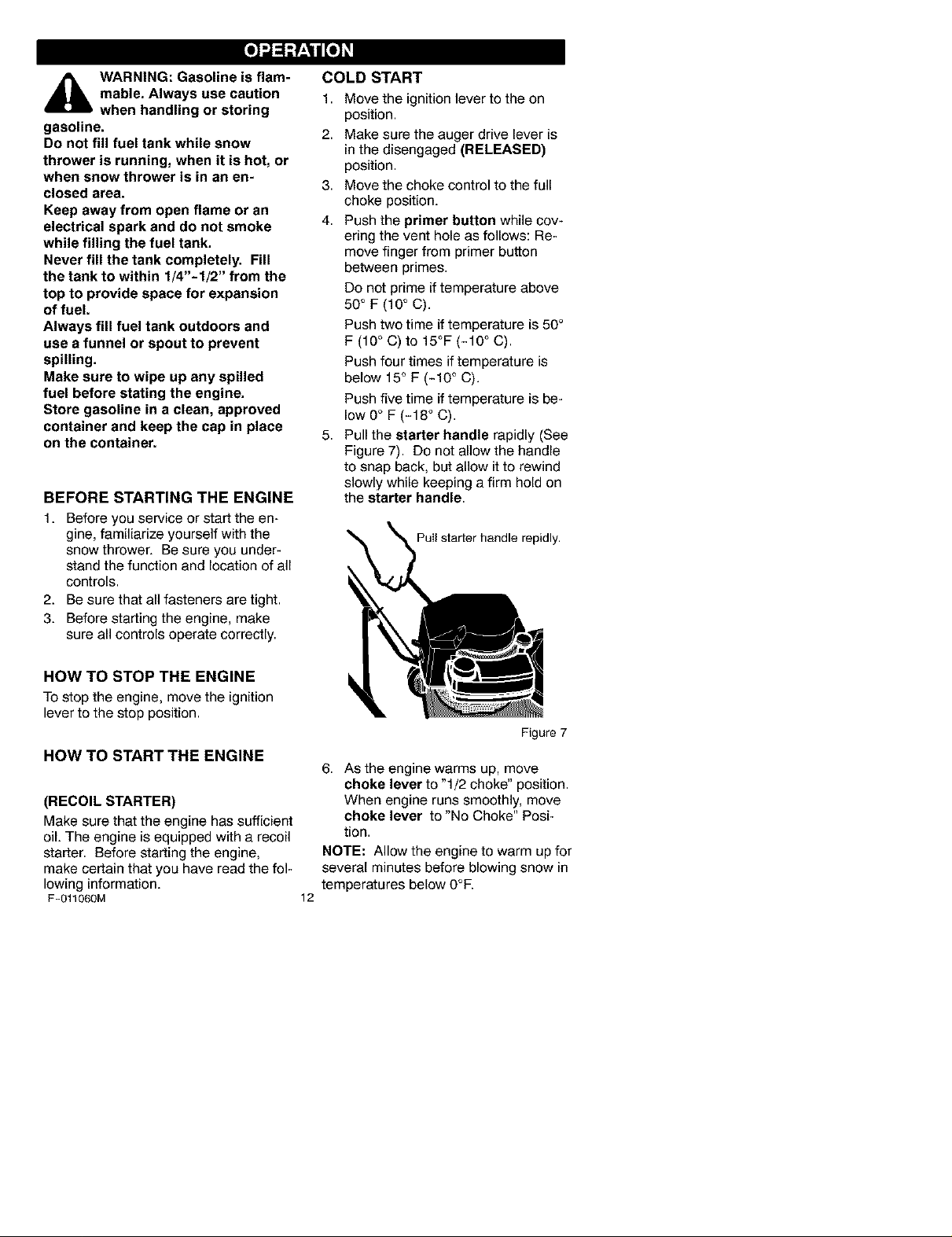
COLD START
1. Move the ignition lever to the on
position.
2. Make sure the auger drive lever is
in the disengaged (RELEASED)
position.
3. Move the choke control to the full
choke position.
4. Push the primer button while cov-
ering the vent hole as follows: Re-
move finger from primer button
between primes.
Do not prime if temperature above
50 ° F (10 ° C).
Push two time iftemperature is 50°
F (10 ° C) to 15°F (-10 ° C).
Push four times if temperature is
below 15° F (-10 ° C).
Push five time iftemperature is be-
low0 ° F (-18 ° C).
5. Pull the starter handle rapidly (See
Figure 7). Do not allow the handle
to snap back, but allow it to rewind
slowly while keeping a firm hold on
the starter handle.
Puil starter handle repidly.
HOW TO STOP THE ENGINE
To stop the engine, move the ignition
lever to the stop position.
HOW TO START THE ENGINE
(RECOIL STARTER)
Make sure that the engine has sufficient
oil. The engine is equipped with a recoil
starter. Before starting the engine,
make certain that you have read the fol-
lowing information.
F-011060M
6. As the engine warms up, move
choke lever to "1/2 choke" position.
When engine runs smoothly, move
choke lever to "No Choke" Posi-
tion.
NOTE: Allow the engine to warm up for
several minutes before blowing snow in
temperatures below 0°E
12
Figure 7
WARM START
If restarting a warm engine after a short
shutdown, leave choke at "OFF" and do
not push the primer button. If the en-
gine fails to start, follow the Cold Start
instructions.
FROZEN STARTER
Ifthe starter is frozen and will not turn
engine:
1. Pull as much rope out of the starter
as possible.
2. Release the starter handle and let it
snap back against the starter.
Ifthe engine still fails to start, repeat the
two previous steps until the engine
starts. Then continue with the direc-
tions for cold start.
To help prevent possible freeze-up of
recoil starter and engine controls, pro-
ceed as follows after each snow remov-
al job.
1. With the engine running, pull the
starter rope hard with a continuous
full arm stroke three or four times.
Pulling of starter rope will produce a
loud clattering sound. This is not
harmful to the engine or starter.
2. With the engine not running, wipe all
snow and moisture from the carbu-
retor cover in area of control levers.
Also move throttle control, choke
control, and starter handle several
times.
_lb WARNING: Never run en-
gine indoors or in enclosed,
poorly ventilated areas. En-
gine exhaust contains CARBON
MONOXIDE, AN ODORLESS AND
DEADLY GAS. Keep hands, feet,
hair and loose clothing away from
any moving parts on engine and
snow thrower.
The temperature of muffler and
nearby areas may exceed 150°1=.
Avoid these areas.
DO NOT allow children or young
teenagers to operate or be near
snow thrower while it is operating.
_lb ARNING: Do not attempt
to remove any item that may
become lodged in auger
without taking the following precau-
tions:
• Release auger drive lever.
• Move the ignition lever to the
stop position to stop the engine.
• Disconnect spark plug wire.
Do not place your hands in the
auger or discharge chute. Use a
pry bar.
SNOW THROWING TIPS
1. When the handle is raised, the au-
ger blades will engage the ground
and the snow thrower will move for-
ward. When the auger drive lever is
released, the auger blades will stop.
If the blades do not stop, see "How
To Adjust The Auger Drive Cable" in
the Service And Adjustment section.
2. Most efficient snow throwing is ac-
complished when the snow is re-
moved immediately after if falls.
3. For complete snow removal, slightly
overlap each previous path.
4. Whenever possible, discharge the
snow down wind.
F-011060M
5,
The distance the snow will be dis-
charged can be adjusted by moving
the discharge chute deflector. Raise
the deflector for more distance or
lower the deflector for less distance.
6,
In windy conditions, lower the chute
deflector to direct the discharged
snow close to the ground where it is
less likely to blow into unwanted
areas.
7. For safety and to prevent damage
to the snow thrower, keep the area
to be cleared free of stones, toys
and other foreign objects.
8. Do not use the auger propelling fea-
ture when clearing gravel or
13
crushedrockdriveways.Movethe
handledowntoslightlyraisetheau-
ger.
9. Theforwardspeedofthesnow
throwerisdependentonthedepth
andweightofthesnow.Experience
willestablishthemosteffective
methodofusingthesnowthrower
underdifferentconditions.
10.Aftereachsnowthrowingjob,allow
theenginetorunforafewminutes.
Thesnowandaccumulatedicewill
meltofftheengine.
11.Cleanthesnowthroweraftereach
use.
12.Removeice,snowanddebrisfrom
theentiresnowthrower.Flushwith
watertoremoveallsaltorother
chemicals.Wipesnowthrowerdry.
DRY AND AVERAGE SNOW
1. Snow up to eight inches deep can
be removed rapidly and easily by
walking at a moderate rate. For
snow or drifts of a greater
depth,slow your pace to allow the
discharge chute to dispose of the
snow as rapidly as the auger re-
ceives the snow.
2. Plan to have the snow discharged in
the direction the wind is blowing.
WET PACKED SNOW
Move slowly into wet, packed snow. If
the wet, packed snow causes the auger
to slow down or the discharge chute be-
gins to clog, back off and begin a series
of short back and forth jabs into the
snow. These short back and forth jabs,
four to six inches, will "belch" the snow
from the chute.
SNOW BANKS AND DRIFTS
In snow of greater depth than the unit,
use the same "jabbing" technique de-
scribed above. Turn the discharge
chute away from the snow bank. More
time will be required to remove snow of
this type than level snow.
F-O11060M 14
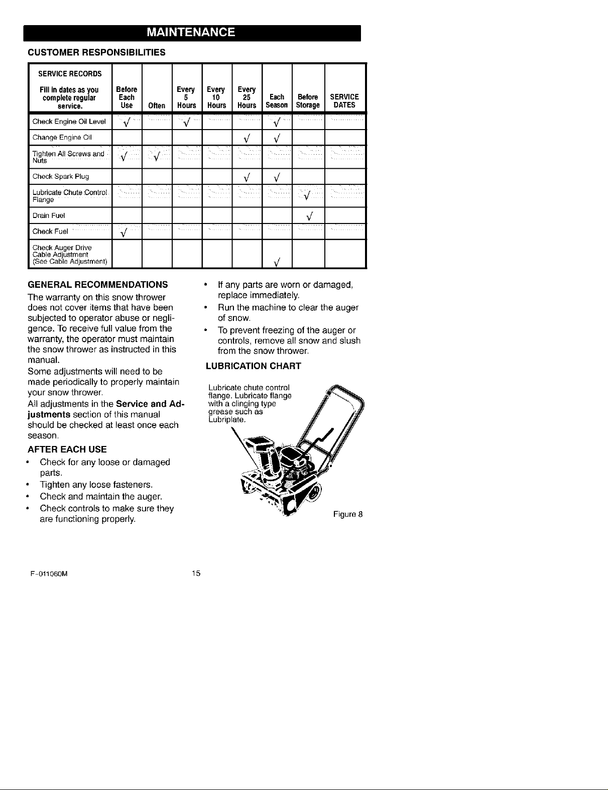
CUSTOMER RESPONSIBILITIES
SERVICERECORDS
Fillindatesasyou Before Every Every Every
completeregular Each 5 10 25 Each Before SERVICE
service. Use Often Hours Hours Hours Season Storage DATES
Check Engine Oil Level _/ _r _/ •
Change Engine Oil _/ _/
Tighten A_IScrews and I I I I I
Nuts
Check Spark Plug _/ _/
Lubricate Chute Control .....
Flange
Drain Fuel ,/
, , , , , , ,
CheckFuel _/ • I I I I I I
Check Auger Drive
_able Ad ustment
See Cab e Ad ustment _/
GENERAL RECOMMENDATIONS
The warranty on this snow thrower
does not cover items that have been
subjected to operator abuse or negli-
gence. To receive full value from the
warranty, the operator must maintain
the snow thrower as instructed in this
manual.
Some adjustments will need to be
made periodically to properly maintain
your snow thrower.
All adjustments in the Service and Ad-
justments section of this manual
should be checked at least once each
season.
AFTER EACH USE
Check for any loose or damaged
parts.
Tighten any loose fasteners.
Check and maintain the auger.
Check controls to make sure they
are functioning properly.
F-Ot1060M 15
If any parts are worn or damaged,
replace immediately.
Run the machine to clear the auger
of snow.
To prevent freezing of the auger or
controls, remove all snow and slush
from the snow thrower.
LUBRICATION CHART
Lubricate chute control
flange, Lubricate flange
with a clinging type
grease such as
Lubriplate.
Figure 8
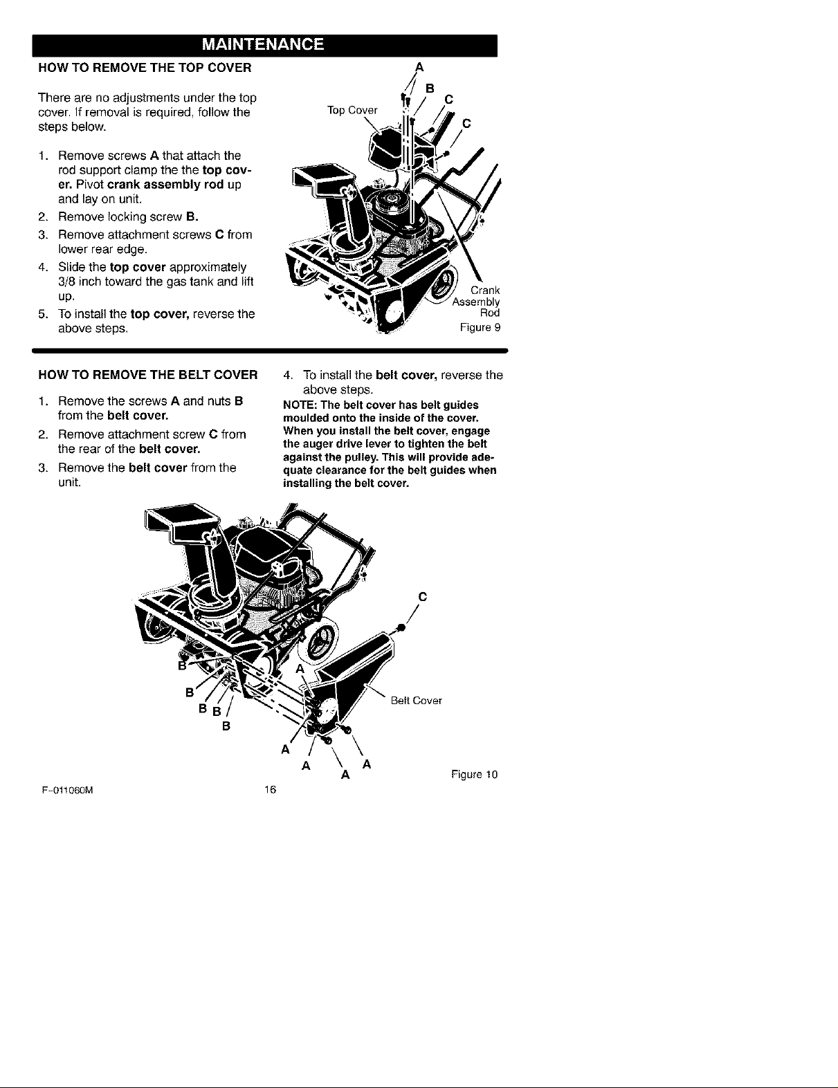
HOW TO REMOVE THE TOP COVER
There are no adjustments under the top
cover. If removal is required, follow the
steps below.
1. Remove screws A that attach the
rod support clamp the the top cov-
er, Pivot crank assembly rod up
and lay on unit.
2. Remove locking screw B.
3. Remove attachment screws C from
lower rear edge.
4. Slide the top cover approximately
3/8 inch toward the gas tank and lift
up.
5. To install the top cover, reverse the
above steps.
Top Cover
A
B
C
C
Crank
ssembly
Rod
Figure 9
HOW TO REMOVE THE BELT COVER
1. Remove the screws A and nuts B
from the belt cover,
2. Remove attachment screw C from
the rear of the belt cover,
3. Remove the belt cover from the
unit.
BI
B
F-01r060M
4. To install the belt cover, reverse the
above steps.
NOTE: The belt cover has belt guides
moulded onto the inside of the cover.
When you install the belt cover, engage
the auger drive lever to tighten the belt
against the pulley. This will provide ade-
quate clearance for the belt guides when
installing the belt cover.
C
Beit Cover
A
A A
16
\
A Figure10
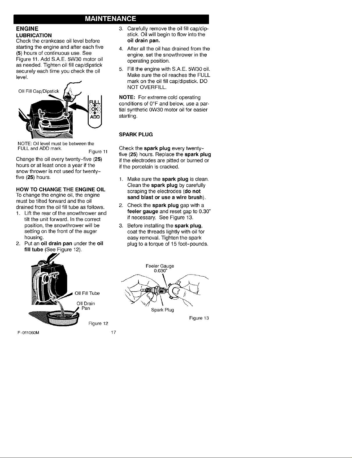
ENGINE
LUBRICATION
Check the crankcase oil level before
starting the engine and after each five
(5) hours of continuous use. See
Figure 11. Add S.A.E. 5W30 motor oil
as needed. Tighten oil fill cap/dipstick
securely each time you check the oil
level.
Oll Fill Cap/Dipstick
NOTE: Oil levelmustbe betweenthe
FULL andADD mark.
Figure 11
Change the oil every twenty-five (25)
hours or at least once a year if the
snow thrower is not used for twenty-
five (25) hours.
HOW TO CHANGE THE ENGINE OIL
To change the engine oil, the engine
must be tilted forward and the oil
drained from the oil fill tube as follows.
1. Lift the rear of the snowthrower and
tilt the unit forward. In the correct
position, the snowthrower will be
setting on the front of the auger
housing.
2. Put an oil drain pan under the oil
fill tube (See Figure 12).
3,
Carefully remove the oil fill cap/dip-
stick. Oil will begin to flow into the
oil drain pan.
4.
After all the oil has drained from the
engine, set the snowthrower in the
operating position.
5.
Fill the engine with S.A.E. 5W30 oil.
Make sure the oil reaches the FULL
mark on the oil fill cap/dipstick. DO
NOT OVERFILL.
NOTE: For extreme cold operating
conditions of 0°F and below, use a par-
tial synthetic 0W30 motor oil for easier
starting.
SPARK PLUG
Check the spark plug every twenty-
five (25) hours. Replace the spark plug
if the electrodes are pitted or burned or
if the porcelain is cracked.
1,
Make sure the spark plug is clean.
Clean the spark plug by carefully
scraping the electrodes (do not
sand blast or use a wire brush).
2,
Check the spark plug gap with a
feeler gauge and reset gap to 0.30"
if necessary. See Figure 13.
3.
Before installing the spark plug,
coat the threads lightly with oil for
easy removal. Tighten the spark
plug to a torque of 15 foot-pounds.
Fill Tube
OII Drain
, Pan
Figure 12
F-011060M 17
Feeler Gauge
0.030"
Spark Plug
Figure 13
_lb WARNING: To prevent acci-
always disconnect the spark plug
wire and place it where it cannot
make contact with the spark plug.
dental starting when making
any adjustments or repairs,
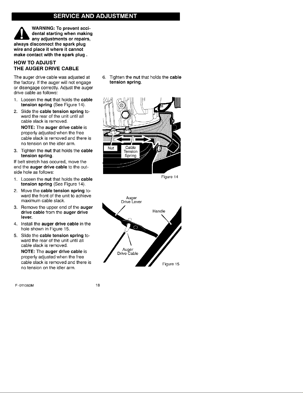
HOW TO ADJUST
THE AUGER DRIVE CABLE
The auger drive cable was adjusted at
the factory. If the auger will not engage
or disengage correctly. Adjust the auger
drive cable as follows:
1. Loosen the nut that holds the cable
tension spring (See Figure 14).
2. Slide the cable tension spring to-
ward the rear of the unit until all
cable slack is removed.
NOTE: The auger drive cable is
properly adjusted when the free
cable slack is removed and there is
no tension on the idler arm.
3. Tighten the nut that holds the cable
tension spring.
If belt stretch has occured, move the
end the auger drive cable to the out-
side hole as follows:
1. Loosen the nut that holds the cable
tension spring (See Figure 14).
2. Move the cable tension spring to-
ward the front of the unit to achieve
maximum cable slack.
3. Remove the upper end of the auger
drive cable from the auger drive
lever.
4. Install the auger drive cable in the
hole shown in Figure 15.
5. Slide the cable tension spring to-
ward the rear of the unit until all
cable slack is removed.
NOTE: The auger drive cable is
properly adjusted when the free
cable slack is removed and there is
no tension on the idler arm.
6. Tighten the nut that holds the cable
tension spring.
Figure 14
Auger
Drive Lever
Handle
\
Auger
Drive Cable
Figure 15
F-011060M 18
HOW TO ADJUST
THE AUGER BRAKE
The auger brake is adjusted at the fac-
tory to assure safe operation of the
snowthrower. If the auger brake needs
an adjustment, follow the steps below:
1. To access the auger brake, tilt the
front of the unit up.
2. Make sure the auger drive belt is
properly installed. See "How To Re-
move The Auger Drive Belt".
3. Make sure the auger drive lever is
in the disengaged (released) posi-
tion.
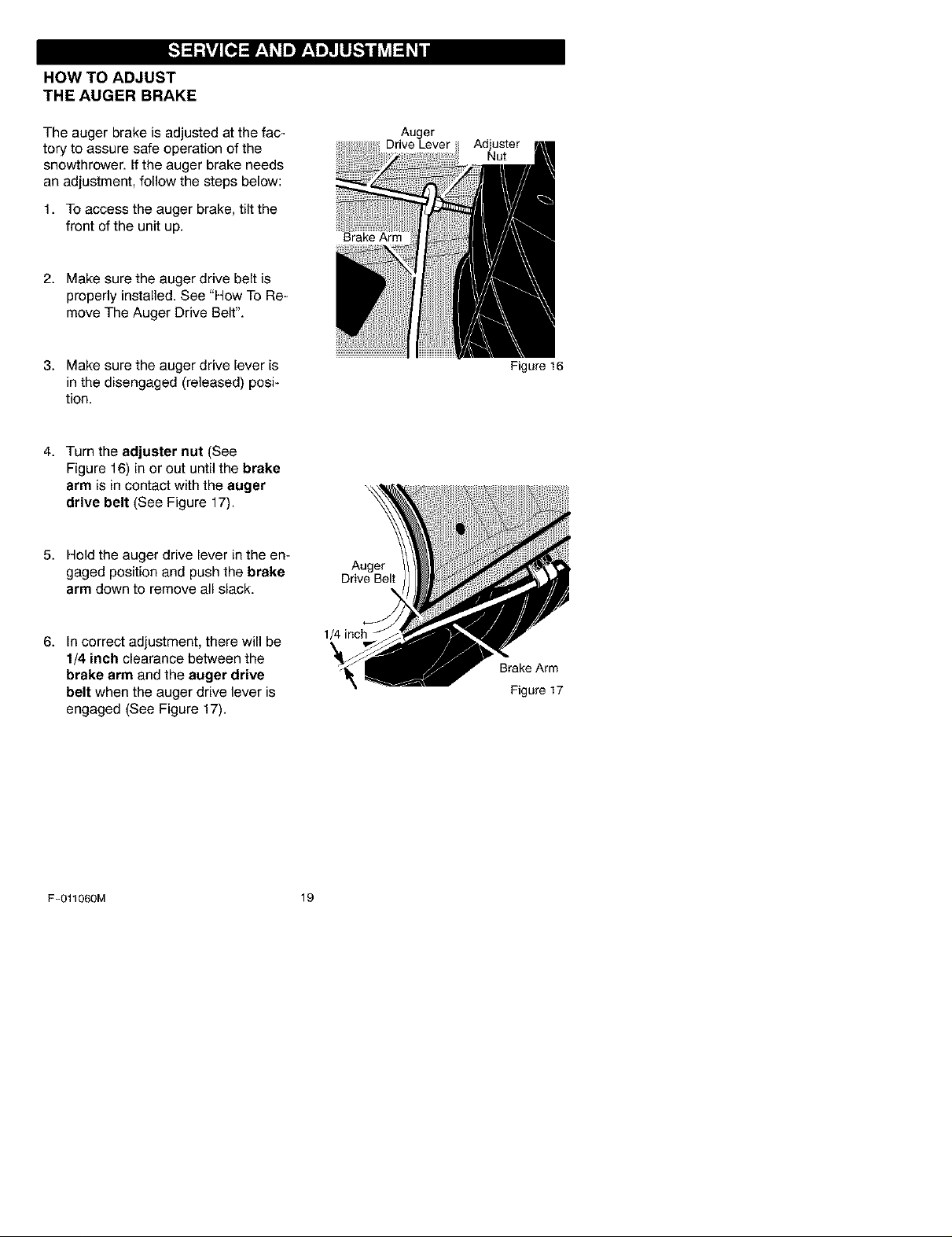
4. Turn the adjuster nut (See
Figure 16) in or out until the brake
arm is in contact with the auger
drive belt (See Figure 17).
5. Hold the auger drive lever in the en-
gaged position and push the brake
arm down to remove all slack.
Brake Arm
Auger
Drive Belt
Auger
Drive Lever
Adjuster
Nut
Figure 16
6. In correct adjustment, there will be
1/4 inch clearance between the
brake arm and the auger drive
belt when the auger drive lever is
engaged (See Figure 17).
F-011060M 19
1/4 inch
Brake Arm
Figure 17
HOW TO REMOVE
THE AUGER DRIVE BELT
The auger drive belt is made of special
construction and must be replaced with
an original equipment belt available
from the nearest Sears Store.
Ifthe auger drive belt is damaged, the
snowthrower will not discharge snow
and will not move forward. Replace the
damaged belt as follows:
1. Disconnect the spark plug wire.
2. Remove the belt cover. See "How
To Remove The Belt Cover".
3. Note the path of the auger drive
belt. For assistance, a diagram de-
cal is provided.
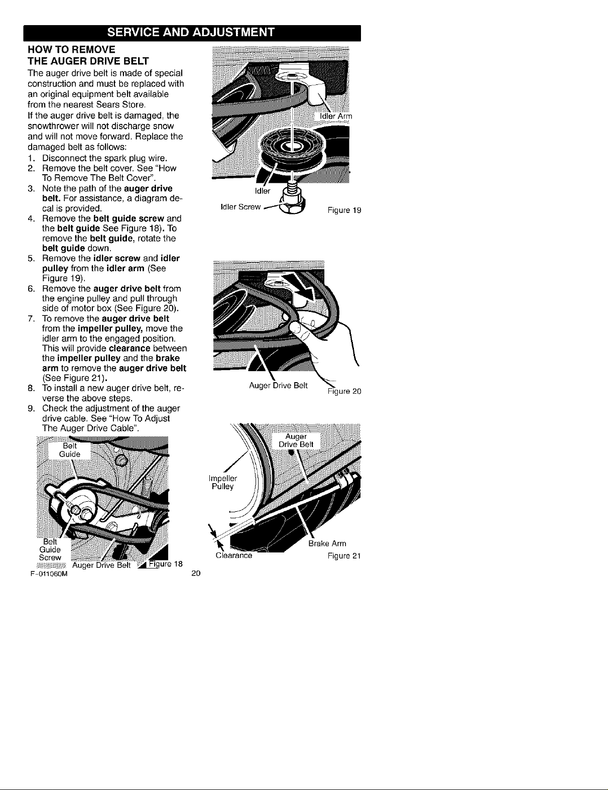
4. Remove the belt guide screw and
the belt guide See Figure 18). To
remove the belt guide, rotate the
belt guide down.
5. Remove the idler screw and idler
pulley from the idler arm (See
Figure 19).
6. Remove the auger drive belt from
the engine pulley and pull through
side of motor box (See Figure 20).
7. To remove the auger drive belt
from the impeller pulley, move the
idler arm to the engaged position.
This will provide clearance between
the impeller pulley and the brake
arm to remove the auger drive belt
(See Figure 21).
8. To install a new auger drive belt, re-
verse the above steps.
9. Check the adjustment of the auger
drive cable. See "How To Adjust
The Auger Drive Cable".
Idler Screw
Auger Drive Belt
Idler Arm
Idler
Figure 19
Figure 20
Belt
Guide
Screw
F-011060M
Auger Drive Belt
ure 18
Impeller
Pulley
Brake Arm
Clearance
20
Figure 21
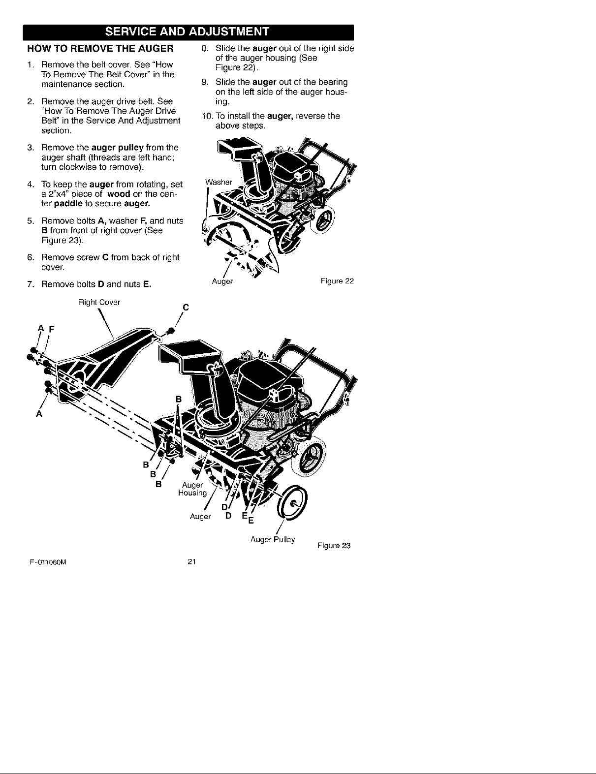
HOW TO REMOVE THE AUGER 8. Slide the auger out of the right side
1. Remove the belt cover. See "How
To Remove The Belt Cover" in the
maintenance section.
of the auger housing (See
Figure 22).
9. Slide the auger out of the bearing
on the left side of the auger hous-
2. Remove the auger drive belt. See
"How To Remove The Auger Drive
Belt" in the Service And Adjustment
section.
ing.
10. To install the auger, reverse the
above steps.
3. Remove the auger pulley from the
auger shaft (threads are left hand;
turn clockwise to remove).
4. To keep the auger from rotating, set
Washer
a 2"x4" piece of wood on the cen-
ter paddle to secure auger,
5. Remove bolts A, washer F, and nuts
B from front of right cover (See
Figure 23).
6. Remove screw C from back of right
cover.
7. Remove bolts D and nuts E.
Auger Figure 22
AF
A
F-011060M
Right Cover
C
/
B
B
B
Auger
Housing
Auger
21
D
Auger Pulley
Figure 23
 Loading...