

Craftsman 536884780 Owner’s Manual
IMPORTANT MANUAL DO NOT THROW AWAY
S AURS
OWNER'S
MANUAL
MODEL NO.
536.884780
Caution:
Read and Follow
All Safety Rules
and Instructions
Before Operating
This Equipment
CRRFT.SMRN
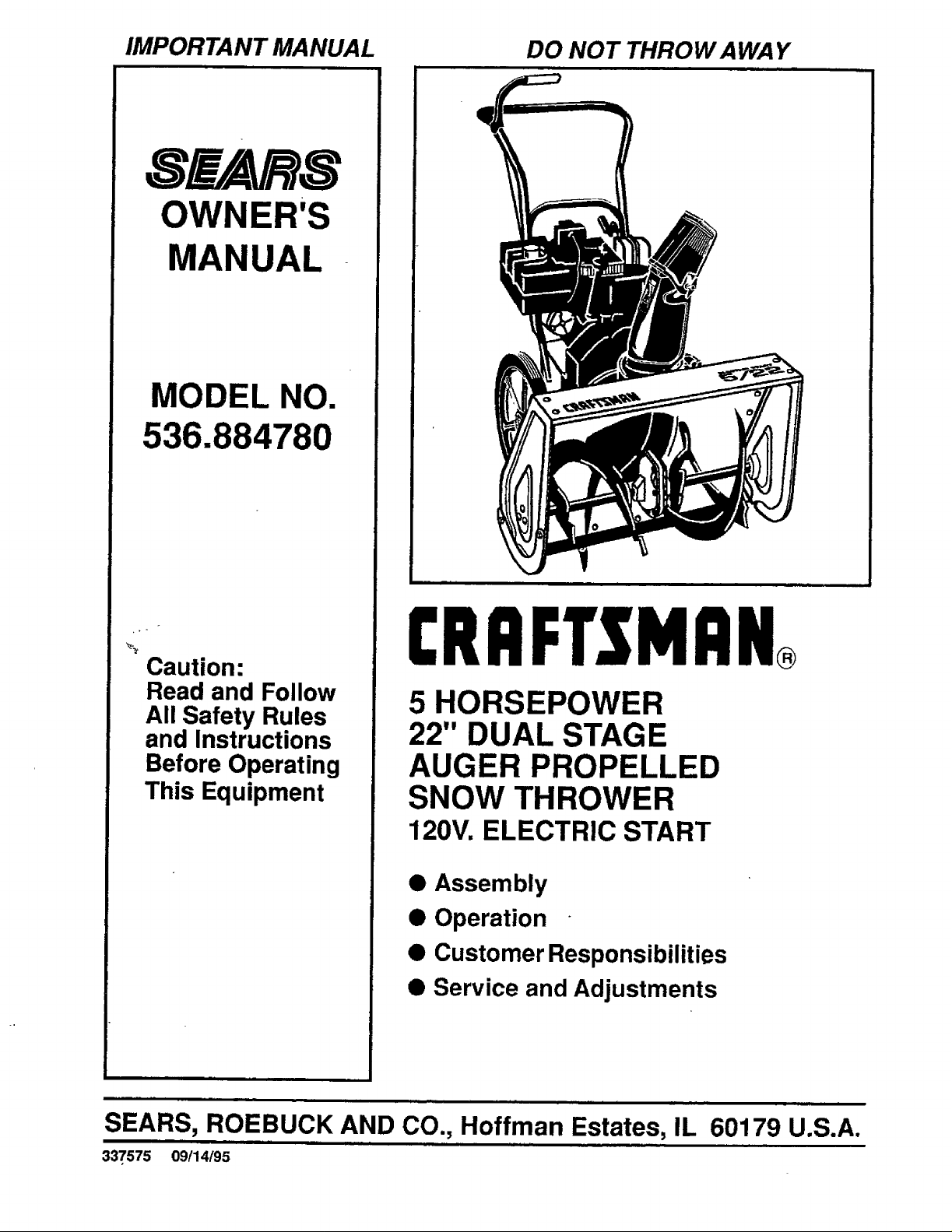
5 HORSEPOWER
22" DUAL STAGE
AUGER PROPELLED
SNOW THROWER
120V. ELECTRIC START
• Assembly
• Operation
• Customer Responsibilities
• Service and Adjustments
nrll
SEARS, ROEBUCK AND CO., Hoffman Estates, IL 60179 U.S.A.
337575 09/14/95
SAFETY RULES
,_ CAUTION: ALWAYS DISCONNECT SPARK PLUG WIRE AND ,_
PLACE WIRE WHERE IT CANNOT CONTACT SPARK PLUG
TO PREVENT ACCIDENTAL STARTING WHEN SETTING-UP,
TRANSPORTING, ADJUSTING OR MAKING REPAIRS.
IMPORTANT
SAFETY STANDARDS REQUIRE OPERATOR PRESENCE CONTROLS TO MINIMIZE THE
RISK OF INJURY. YOUR SNOW THROWER IS EQUIPPED WITH SUCH CONTROLS. DO NOT
ATTEMPT TO DEFEAT THE FUNCTION OF THE OPERATOR PRESENCE CONTROL UNDER
ANY CIRCUMSTANCES.
TRAINING
1. Read the operator's manual carefully. Be
thoroughly familiar with the controls and the
proper use of the snow thrower. Know how to
stop the snow thrower and disengage the
controls quickly.
2. Never allow children to operate the snow thrower
and keep them away while it is operating. Never
allow adults to operate the snow thrower without
proper instruction. Do not carry passengers.
3. Keep the area o! operation clear of all persons,
particularly small children, and pets.
4. Exercise caution to avoid slipping or falling,
especially when operating in reverse.
PREPARATION
1. Thoroughly inspect the area where the snow
thrower is to be used and remove all doormats,
sleds, boards, wires, and other foreign objects.
2. Disengage all clutches and shift into neutral
before starting the engine (motor).
3. Do not operate the snow thrower without wearing
adequate winter outer garments. Wear footwear
that will improve footing on slippery surfaces.
4. Handle fuel with care; it is highly flammable.
(a) Use an approved fuel container.
(b) Never remove fuel tank cap or add fuel to a
runningengineor hot engine.
(c) Fill fuel tank outdoors with extreme care.
Never fil!fueltank indoors.
(d) Replace fuel tank cap securely and wipe up
spilled fuel.
(e) Never store fuel or snow thrower'with fuel in
the tank inside of a building where fumes'may
reach an open flame or spark.
(f) Check fuel supply before each use, allowing
space for expansion as the heat of the engine
(motor) and/or sun can cause fuel to expand.
.
Use extension cords and receptacles as specifie_l
by the manufacturer for all snow throwers with.
electric drive motors or electric starting motors.
6. Adjust the snow thrower height to clear gravel or
crushed rock surfaces.
7. Never attempt to make any adjustments while the
engine (motor) is running (except when
specifically recommended by the manufacturer).
8. Let engine (motor) and snow thrower adjust to
outdoor temperatures before starting to clear
snow.
9. Always wear safety glasses or eye shields during
operation or while performing an adjustment or
repair to protect eyes from foreign objects that
may be thrown from the snow thrower.
OPERATION
1. Do not put hands or feet near or under rotating
parts. Keep clear of the discharge open=ng at all
times.
2. Exercise extreme caution when operating on or
crossing gravel drives, walks, or roads. Stay aler_
for hidden hazards or traffic.
.
After striking a foreign object, stop the engine
(motor), remove the wire from the spark plug,
disconnect the cord on electric motors,
thoroughly inspect the snow thrower for any
damage, and repair the damage before restarting
and operating the snow thrower.
.
If the snow thrower shoutd start to vibrate
abnormally, stop the (motor) and check
immediately for the cause. Vibration =sgenerally
a warning of trouble.
5. Stop the engine (motor) whenever you leave the
operating position, before unclogging the auger/
impeller housing or discharge guide, and when
making any repairs, adjustments, or inspections.
6. When cleaning, repairing, or respecting, make
certain the auger/impeller and all moving parts
have stopped. Disconnect the spark plug wire
and keep the wire away from the plug to prevent
accidental starting.
7. Take all possible precautions when leaving the
snow thrower unattended. Disengage the auger/
impeller, shift to neutral, stop engine, and
remove key.
SAFETY RULES
8. Do not run the engine indoors,except when starting
the engine and for transporting the snow thrower in
or out of the building. Open the outside doors;
exhaust fumes are dangerous (containing CARBON
MONOXIDE,an ODORLESS and DEADLY GAS).
9• Do not clear snow across the face of slopes.
Exercise caution when changing direction on
slopes. Do not attempt to clear steep slopes.
10. Never operate the snow thrower without proper
guards, plates or other safety protective devices
in place.
11. Never operate the snow thrower near glass
enclosures, automobiles, window wells,
drop-oils, and the like without proper adjustment
of the snow discharge angle, Keep children and
pets away.
12. Do not overload the machine capacity by
attempting to clear snow at too fast a rate.
13. Never operate the snow thrower at high transport
speeds on slippery surfaces. Look behind and
use care when backing•
14. Never direct discharge at bystanders or allow
anyone in front of the snow thrower.
15. Disengage power to the auger/impeller when
snow thrower is transported or not in use.
16. Use only attachments and accessories approved
by the manufacturer of the snow thrower (such
as tire chains, electric start kits, etc.).
17. Never operate the snow thrower without good
visibilityor light. Always be sure of your footing,
and keep a firm hold on the handles. Walk; never
run.
MAINTENANCE AND STORAGE
1. Check shear bolts and other bolts frequentty for
proper tightness to be sure the snow thrower
is in safe working condition.
2. Never store the snow thrower with fuel in the fuel
tank inside a building where ignition sources are
present such as hot water and space heaters,
clothes dryers, and the like. Allow the engine to
cooi before storing in any enclosure.
3_ Always refer to operator's manual instructions
for important details if the snow thrower is to be
stored for an extended period.
4. Maintain or replace safety and instructionlabels,
as necessary.
5. Run the snow thrower a few minutes after
throwing snow to prevent freeze-up of the auger/
impeller.
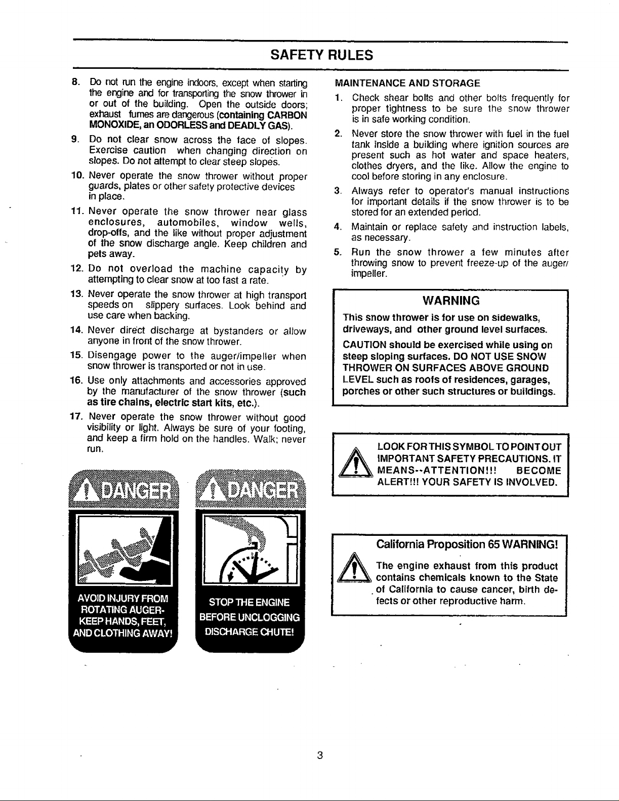
WARNING
This snow thrower is for use on sidewalks,
driveways, and other ground level surfaces.
CAUTION should be exercised while using on
steep sloping surfaces. DO NOT USE SNOW
THROWER ON SURFACES ABOVE GROUND
LEVEL such as roofs of residences, garages,
porches or other such structures or buildings.
LOOK FORTHIS SYMBOL TO POINTOUT
iMPORTANT SAFETY PRECAUTIONS. tT
MEANS--ATTENTION!!! BECOME
ALERT!!7 YOUR SAFETY IS INVOLVED.
California Proposition 65WARNING!
The engine exhaust from this product
contains chemicals known to the State
• of California to cause cancer, birth de-
fects or other reproductive harm.
CONGRATULATIONSonyour purchase of a SEARS
Craftsman Snow Thrower. It has been designed, engi-
neered and manufactured to give you the best possible
dependabilityand performance.
Should you experience any problem you cannot easily
remedy, please contact your nearest SEARS Service
CentedDepartment. SEARS hascompetent, weU-trained
technicians and the proper toolsto service or repair this
unit.
Please read and retain this manual. The instructions will
enable youto assemble and maintain your snowthrower
properly. Always observe the "SAFETY RULES."
MODEL
NUMBER 536.884780
SERIAL
NUMBER
DATE OF
PURCHASE
THE MODEL AND SERIAL NUMBERS WILL BE
FOUND ON A DECAL ATTACHED TO THE REAR
OF THE SNOW THROWER HOUSING.
YOU SHOULD RECORD BOTH SERIAL NUMBER
AND DATEOF PURCHASE AND KEEP INA SAFE
PLACE FOR FUTURE REFERENCE.
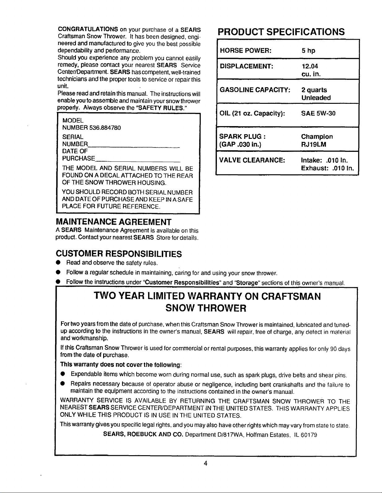
PRODUCT SPECIFICATIONS
HORSE POWER: 5 hp
DISPLACEMENT: 12.04
cu. in.
GASOLINE CAPACITY:
OIL (21 oz. Capacity): SAE 5W-30
SPARK PLUG : Champion
(GAP .030 in.) RJ19LM
VALVE CLEARANCE: Intake: .010 In,
2 quarts
Unleaded
i
Exhaust: .010 In.
MAINTENANCE AGREEMENT
A SEARS MaintenanceAgreement isavailable onthis
product.Contact yournearestSEARS Store for details.
CUSTOMER RESPONSIBILITIES
• Read and observe the safety rules.
• Followa regular schedule in maintaining,caring for and usingyour snow thrower.
• Followthe instructionsunder "Customer Responsibilities" and "Storage" sectionsofthis owner's manual.
TWO YEAR LIMITED WARRANTY ON CRAFTSMAN
SNOW THROWER
For twoyears from the date of purchase, when this Craftsman Snow Thrower is maintained, lubricated and tuned-
up according to the instructions in the owner's manual, SEARS will repair, free of charge, any defect in material
and workmanship.
If this Craftsman Snow Thrower is used for commercial or rental purposes, this warranty applies for only 90 days
from the date of purchase.
This warranty does not cover the following:
• Expendable items which become wornduring normal use, such as spark plugs, drive belts and shear pins.
• Repairs necessary because of operator abuse or negligence, including bent crankshafts and the failure to
maintain the equipment according to the instructions contained inthe owner'smanual.
WARRANTY SERVICE IS AVAILABLE BY RETURNING THE CRAFTSMAN SNOW THROWER TO THE
NEAREST SEARS SERVICE CENTER/DEPARTMENT iN THE UNITED STATES. THIS WARRANTY APPLIES
ONLY WHILE THIS PRODUCT tS IN USE IN THE UNITED STATES.
This warranty gives you specific legal rights, and you mayalso have other rights which may vary from state to state.
SEARS, ROEBUCK AND CO. Department D/817WA, Hoffman Estates, IL 60179
4
im=l ii i
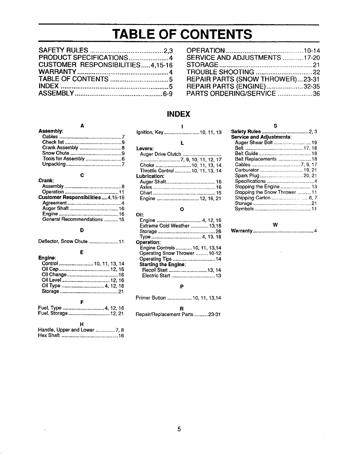
TABLE OF CONTENTS
SAFETY RULES ........................................ 2,3
PRODUCT SPECIFICATIONS ...................... 4
CUSTOMER RESPONSIBILITIES ..... 4,15-16
WARRANTY .................................................. 4
TABLE OF CONTENTS. ............................... 5
INDEX ........................................................... 5
ASSEMBLY .......................................... •...... 6-9
A
Assembly:
Cables ............................................. 7
Check list ......................................... 9
Crank Assemb[y .............................. 8
Snow Chute ..................................... 9
Tools for Assembly .......................... 6
Unpacking ........................................ 7
C
Crank:
Assembly ......................................... 8
Operation ....................................... ! 1
Customer Rssponsibilities....4,15-16
Agreement ....................................... 4
Auger Shaft ................................... 16
Engine ........................................... 16
General Recommendations .......... I5
Deflector, Snow Chute ..................... 11
E
Engine:
Control......................... lO, 11, 13, 14
Oil Cap ..................................... 12, 16
Oil Change ..................................... 16
Oil Level................................... 12, 16
Oil Type ............................... 4, 12, 16
Storage .......................................... 21
F
Fuel, Type .............................. 4, 12, 16
Fuel, Storage .............................. 12, 21
H
Handle, Upper and Lower .............. 7, 8
Hex Shaft ......................................... 16
Ignition, Key.......................... I 0, ! 1, 13
Levers:
Auger Drive Clutch ............................
............;................ 7, 9, 10, 11, !2, 17
Choke .......................... 10, 11, 13, 14
Throttle Control............ 10, t 1, 13, 14
Lubrication:
Auger Shaft .................................... 16
Axles .............................................. 16
Chart .............................................. 15
Engine ............................... 12, 16, 21
Oil:
Engine ................................. 4, 12, 16
Extreme Cold Weather ............. 13,18
Storage .......................................... 26
Type ..................................... 4, 13, 18
Operation:
Engine Controls............ 10, 11, 13,14
Operating Snow Thrower ......... 10-12
Operating Tips ............................... t4
Starting the Engine:
Recoil Start............................ 13, 14
Electric Start ................................ 13
Primer Button .................. 10, 11, 13,14
RepaidReplacement Parts .......... 23-31
INDEX
I
L
o
R
OPERATION .......................................... t 0-14
SERVICE AND ADJUSTMENTS ........... ! 7-20
STORAGE ................................................... 2t
TROUBLE SHOOTING ............................... 22
REPAIR PARTS (SNOW THROWER)...23-31
REPAIR PARTS (ENGINE) .................... 32-35
PARTS ORDERING/SERVICE ................... 36
S
Safety Rules .................................. 2, 3
Service and Adjustments:
Auger Shear Bolt ........................... 19
Belt .......................................... 17, 18
Belt Guide ...................................... 18
Belt Replacements ........................ 18
Cables ................................... 7, 9, 17
Carburetor ............................... 19, 21
Spark Plug ............................... 20, 21
Specifications .................................. 4
Stopping the Engine ..................... 13
Stopping the Snow Thrower .......... 11
Shipping Carton .......................... 6, 7
Storage .......................................... 21
Symbols ........................................ 11
W
Warranty ............................................ 4
5
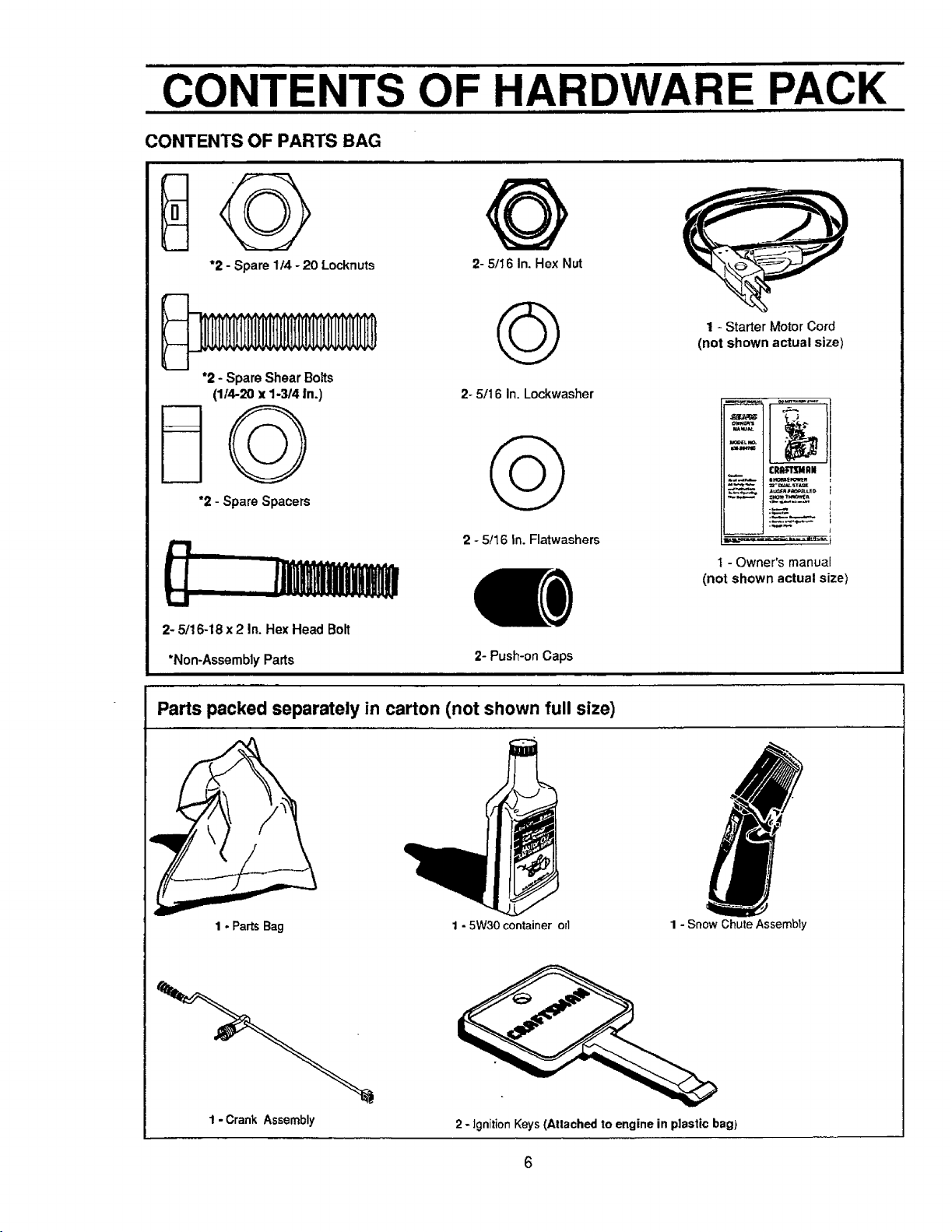
CONTENTS OF HARDWARE PACK
i
CONTENTS OF PARTS BAG
*2 - Spare 1/4 -20 Locknuts 2- 5/16 In.Hex Nut
1 - Starter Motor Cord
(not shown actual size)
*2 - Spare Shear Botts
(1/4-20 x 1-3/4 in.)
*2 - Spare Spacers
2- 5/16 In. Lockwasher
2 - 5/16 In. Flatwashers
t.i
2- 5/16-18 x 2 In. Hex Head Bolt
*Non-Assembly Parts 2- Push-on Caps
Parts packed separately in carton (not shown full size)
_L r,o.
_u_ _
FRR_IU411N
_ =h'amE_w
1 - Owner's manual
(not shown actual size)
1- PartsBag
1- CrankAssembly
1 - 5W30 container orl 1 - Snow Chute Assembly
2 - ignition Keys (Atlached to engine in plastic bag)
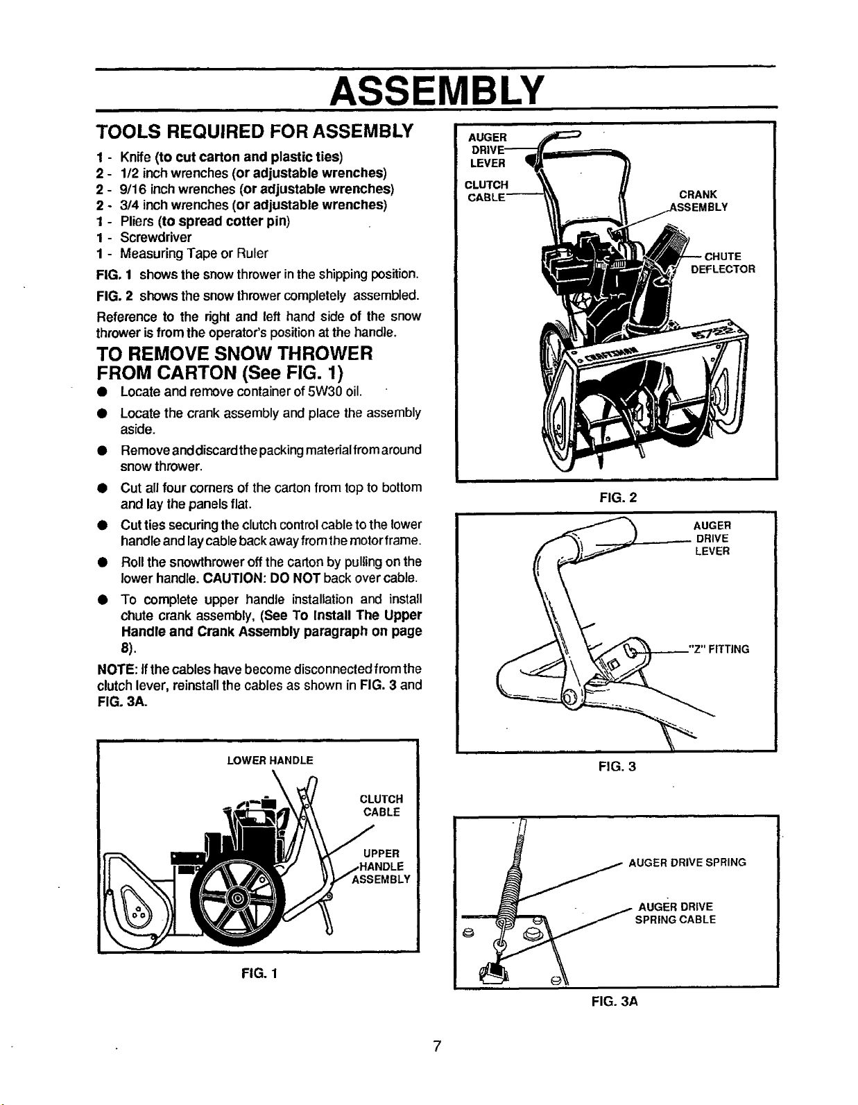
ASSEMBLY
TOOLS REQUIRED FOR ASSEMBLY
1 - Knife(to cut carton and plastic ties)
2 - 112inch wrenches (or adjustable wrenches)
2 - 9/16 inch wrenches (or adjustable wrenches)
2 - 3/4 inch wrenches (or adjustable wrenches)
1 - Pliers (to spread cotter pin)
1- Screwdriver
1 - Measuring Tape or Ruler
FIG. 1 shows the snowthrowerin theshippingposition.
FIG. 2 shows the snowthrowercompletely assembled.
Reference to the right and left hand side of the snow
throwerisfrom the operator'spositionat the handle.
TO REMOVE SNOW THROWER
FROM CARTON (See FIG. 1)
• Locate and remove container of 5W30 oil.
• Locatethe crank assemblyand place the assembly
aside.
• Remove anddiscardthepacking materialfromaround
snow thrower.
• Cut all four comers of the carton from top to bottom
and lay the panels flat.
• Cutties securing the clutch control cable to the lower
handle and laycable back awayfrom the motor frame.
• Roll the snowthrower off the carton by pulling on the
lower handle. CAUTION: DO NOT back over cable.
• To complete upper handle installation and install
chute crank assembly, (See To Install The Upper
Handle and Crank Assembly paragraph on page
8).
NOTE: if the cables havebecomedisconnectedfrom the
clutchlever, reinstallthe cables as shown in FIG. 3 and
FIG. 3A.
AUGER
LEVER
CLUTCH
CRANK
}LY
DEFLECTOR
FIG. 2
AUGER
DRIVE
LEVER
FITTING
LOWER HANDLE
FIG. 1
CLUTCH
CABLE
UPPER
SSEMBLY
FIG. 3
AUGER DRIVE SPRING
FIG. 3A
7
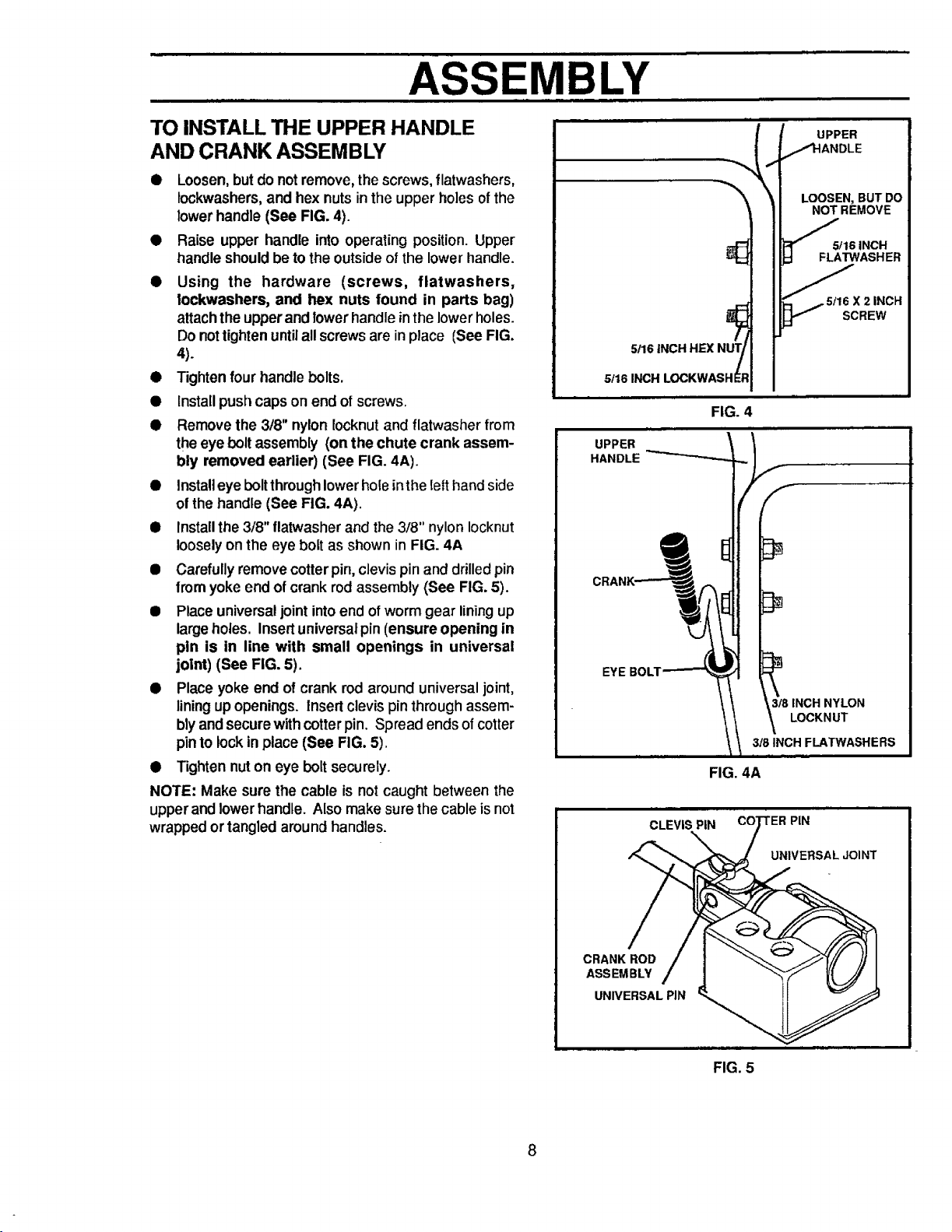
ASSEMBLY
TO INSTALL THE UPPER HANDLE
AND CRANK ASSEMBLY
• Loosen, but donotremove, the screws, flatwashers,
lockwashers, and hex nuts in the upper holes of the
lower handle (See FIG. 4).
• Raise upper handle into operating position. Upper
handle should be to the outside of the lower handle.
• Using the hardware (screws, flatwashers,
lockwashers, and hex nuts found in parts bag)
attachtheupperand lowerhandle inthe lowerholes.
Do nottighten untilall screws are inplace (See FIG,
4).
• Tightenfour handle bolts.
• Install push caps on end of screws.
• Removethe 3/8" nylon Iocknutand flatwasher from
theeye bolt assembly (on the chute crank assem-
bly removed earlier) (See FIG. 4A).
• Install eye bolt through lowerhole inthe Ietthand side
of the handle (See FIG. 4A).
• Install the 3/8" flatwasher and the 3/8" nylon Iocknut
loosely on the eye bolt as shown in FIG. 4A
• Carefully remove cotter pin, clevis pin and drilled pin
from yoke end of crank rod assembly (See FIG. 5).
• Place universal joint into end of worm gear lining up
large holes. Insert universal pin (ensure opening in
pen is in line with small openings in universal
joint) (See FIG. 5).
• Place yoke end of crank rod around universaljoint,
liningupopenings. Insert clevis pin throughassem-
blyand securewithcotter pin. Spread endsofcotter
pinto lockin place (See FIG. 5).
• Tighten nuton eye bolt securely.
NOTE: Make sure the cable is not caught between the
upperand lowerhandle. Also make sure the cable isnot
wrapped ortangled aroundhandles.
5!16 INCH HEX NUT/
5116 INCH LOCKWASHE$
UPPER
HANDLE "_
CLEVIS PiN
/
FIG. 4
/,f
FIG. 4A
LOOSEN,BUTDO
NOT REMOVE
/
FLATWASHER
'/_5tl 6 X 2 INCH
f
LOCKNUT
3t8 INCH NYLON
318INCH
PIN
UNIVERSAL JOINT
5/16 INCH
SCREW
CRANK ROD
ASSEMBLY
UNIVERSAL PIN
FIG. 5
8
ASSEMBLY
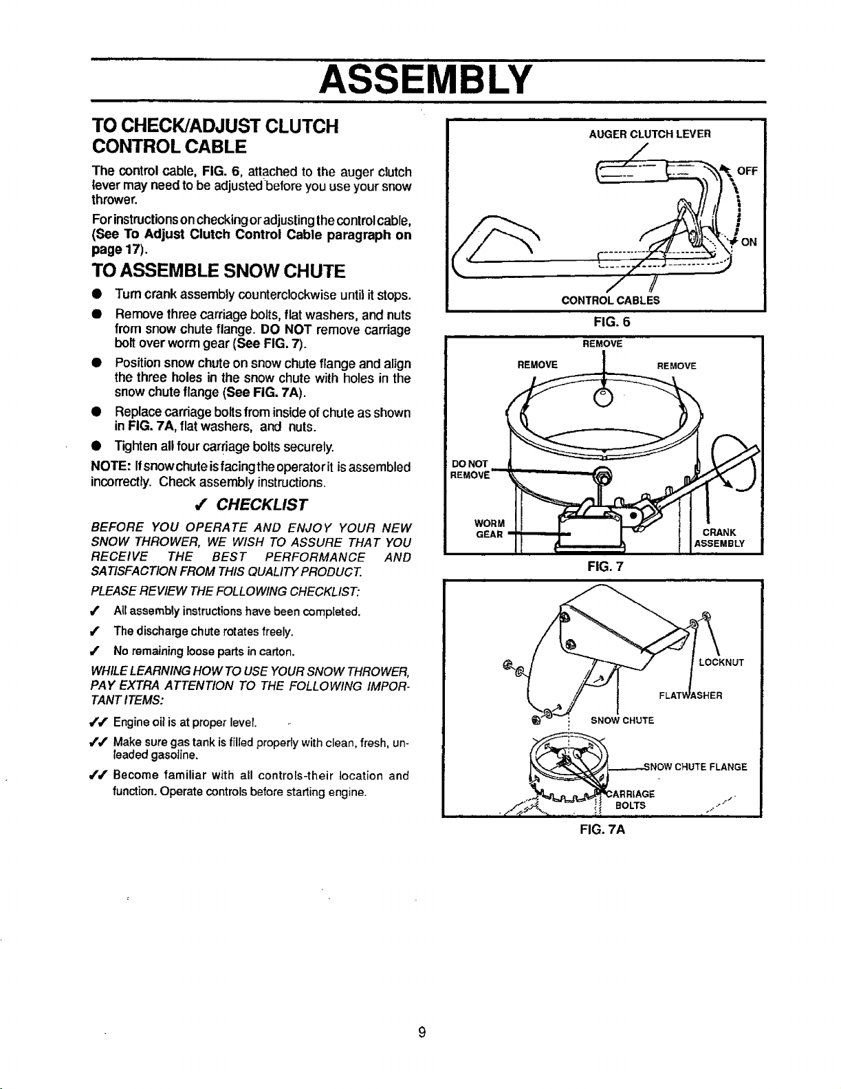
TO CHECK/ADJUST CLUTCH
CONTROL CABLE
The control cable, FIG. 6, attached to the auger clutch
lever may need to be adjustedbefore you use your snow
thrower.
Forinstructionsoncheckingoradjusting the control cable,
(See To Adjust Clutch Control Cable paragraph on
page 17).
TO ASSEMBLE SNOW CHUTE
• Turn crank assembly counterclockwise until it stops.
• Remove three carriage bolts, flat washers, and nuts
from snow chute flange. DO NOT remove carriage
bolt over worm gear (See FIG. 7).
• Position snow chute on snow chute flange and alJgn
the three holes in the snow chute with holes in the
snow chute flange (See FIG. 7A).
• Replacecarriage bolts from inside of chute as shown
in FIG. 7A, flat washers, and nuts.
• Tighten allfour carriage boltssecurely.
NOTE: Ifsnowchute isfacingtheoperatorit isassembled
incorrectly. Check assembly instructions.
,f CHECKLIST
BEFORE YOU OPERATE AND ENJOY YOUR NEW
SNOW THROWER, WE WISH TO ASSURE THAT YOU
RECEIVE THE BEST PERFORMANCE AND
SATISFACTION FROM THIS QUALITY PRODUCT.
PLEASE REVIEW THE FOLLOWING CHECKLIST:
4' Atl assembly instructions have been completed.
/ The discharge chute rotates freely.
/ No remaining loose parts in carton.
WHILE LEARNING HOW TO USE YOUR SNOW THROWER,
PAY EXTRA ATTENTION TO THE FOLLOWING IMPOR-
TANT ITEMS:
/#" Engine oil is at proper lever.
/,/' Make sure gas tank is filledproperly with clean, fresh, un-
leaded gasoline.
J/ Become familiar with all controEs-their location and
function. Operate controls before starting engine.
AUGER CLUTCH LEVER
/_
1
/ /
CONTROL CABLES
FIG. 6
REMOVE
DO NOT
REMOVE
WOR M
GEAR
FIG. 7
LOCKNUT
iSHER
: SNOW CHUTE
_E ,o..,.jNOWCHUTEFLANGE
FIG. 7A
9
OPERATION
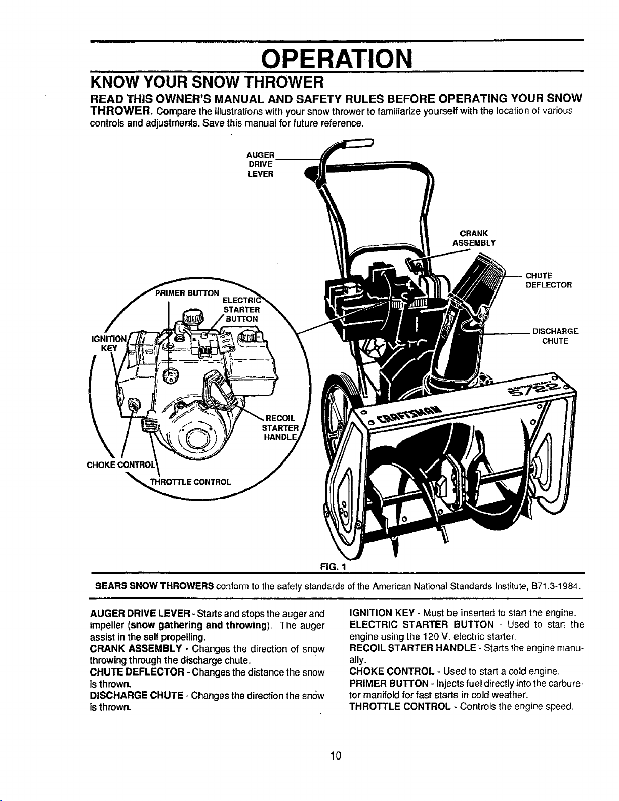
KNOW YOUR SNOW THROWER
READ THIS OWNER'S MANUAL AND SAFETY RULES BEFORE OPERATING YOUR SNOW
THROWER. Compare the illustrationswith your snow throwerto familiarize yourselfwith the locationof various
controlsand adjustments.Save thismanual for future reference.
AUGER
DRIVE
LEVER
CRANK
ASSEMBLY
CHUTE
DEFLECTOR
STARTER
DISCHARGE
KEY
CHUTE
STARTER
HANi
THRO'I'IrLE CONTROL
FIG. 1
SEARS SNOW THROWERS conform to the safety standards of the American National Standards Institute, B71.3-1984.
AUGER DRIVE LEVER - Startsand stops the auger and
impeller (snow gathering and throwing). The auger
assist inthe self propelling.
CRANK ASSEMBLY - Changes the direction of snow
throwingthroughthe dischargechute.
CHUTE DEFLECTOR - Changes the distance the snow
isthrown.
DISCHARGE CHUTE - Changes the direction the sn6w
isthrown.
IGNITION KEY - Must be inserted to start the engine.
ELECTRIC STARTER BUTTON - Used to start the
engine using the 120 V. electric starter.
RECOIL STARTER HANDLE- Starts the engine manu-
ally.
CHOKE CONTROL - Used to start a cold engine.
PRIMER BU'I-I'ON - Injects fuel directty into the carbure-
tor manifold for fast starts incold weather.
THROTTLE CONTROL - Controls the engine speed.
10
OPERATION
The operation ofany snowthrower can resultinforeign objects being thrown intothe
eyes, whichcan resultinsevere eye damage. Always wear safety glasses or eye
shieldswhileoperating the snow thrower.
We recommend standard safety glasses available at SEARS Retail Stores or
Service Centers.
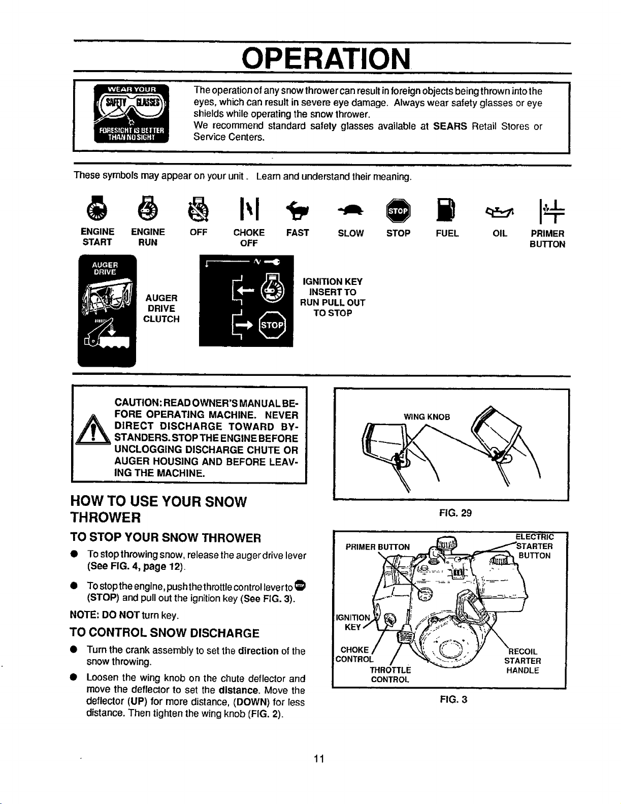
These symbols may appear on your unit. Learn and understand theirmeaning.
ENGINE ENGINE OFF CHOKE FAST SLOW STOP FUEL
START RUN OFF
IGN_ION KEY
AUGER
DRIVE
CLUTCH
INSERTTO
RUN PULL OUT
TO STOP
CAUTION: READ OWNER'S MAN UAL BE-
FORE OPERATING MACHINE. NEVER
WING KNOB
DIRECT DISCHARGE TOWARD BY-
STANDERS. STOP THE ENGINE BEFORE
UNCLOGGING DISCHARGE CHUTE OR
AUGER HOUSING AND BEFORE LEAV-
ING THE MACHINE.
HOW TO USE YOUR SNOW
THROWER
OIL PRIMER
BUTTON
FIG. 29
TO STOP YOUR SNOW THROWER
To stop throwingsnow, release theauger drivelever
(See FIG. 4, page 12).
• TOstopthe engine, push the throttlecontrollevertoI_
(STOP) and pull outthe ignitionkey(See FIG. 3).
NOTE: DO NOT turn key.
TO CONTROL SNOW DISCHARGE
Turn the crank assembly to set the direction of the
snow throwing.
Loosen the wing knob on the chute deflector and
move the deflector to set the distance. Move the
deflector (UP) for more distance, (DOWN) for less
distance. Then tighten the wingknob (FIG. 2).
11
PRIMER BUTTON
CHOKE
CONTROL
THROTTLE
CONTROL
ELECTRIC
;R
BUTTON
STARTER
HANDLE
FIG. 3
OPERATION
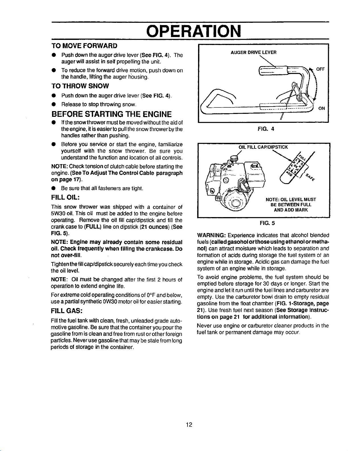
TO MOVE FORWARD
• Pushdown the auger drive lever (See FIG. 4). The
augerwill assist in self propellingthe unit.
• To reduce the forward ddve motion,push down on
the handle, liftingthe auger fiousing.
TO THROW SNOW
• Pushdown the auger drive lever (See FIG. 4).
• Release to stopthrowing snow.
BEFORE STARTING THE ENGINE
• Ifthe snow thrower must be moved without the aid of
the engine, itis easier to pull the snowthrower bythe
handles rather than pushing.
• Before you service or start the engine, tamiliarize
yourself with the snow thrower. Be sure you
understand the function and location of all controls.
NOTE: Check tension of clutch cable before starting the
engine. (SeeTo Adjust The Control Cable paragraph
on page 17).
• Be surethat all fasteners are tight.
FILL OIL:
This snow thrower was shipped with a container of
5W30 oil. This oiJ must be added to the engine before
operating. Remove the oil fill cap/dipstick and fill the
crank case to (FULL) line on dipstick (21 ounces) (See
FIG. 5).
NOTE: Engine may already contain some residual
oil. Check frequently when fllllngthe crankcase. Do
not over-fill.
Tighten the fillcap!dipstick securely each time you check
the oil level.
NOTE: Oil must be changed after the first 2 hours of
operation to extend engine life.
Forextreme cold operating conditions of 0°F and below,
use a partial synthetic 0W30 motor oil for easier starting.
FILL GAS:
Fill thefuel tank with clean,fresh, unleaded grade auto-
motive gasoline. Be sure that the container you pour the
gasoline from is clean and free from rustorother foreign
particles. Never use gasoline that may be stale from long
periods o| storage in the container.
FIG. 4
OIL FILL CAPIDIPSTICK
i NOTE: OIL LEVEL MUST
WARNING: Experience indicates that alcohol blended
fuels (called gasohol orthose using ethanolor metha-
nol) can attract moisturewhich leadsto separation and
formationof acids during storage the fuel system of an
engine while instorage. Acidic gas can damage thefuel
system of an engine while in storage.
To avoid engine problems, the fuel system should be
emptied before storage for 30 days or longer. Start the
engine and let it run until the fuel lines and carburetor are
empty. Use the carburetor bowl drain to empty residual
gasoline from the float chamber (FIG. 1-Storage, page
21). Use fresh fuel next season (See Storage instruc-
tions on page 21 tot additional information).
Never use engine or carburetor cleaner productsin the
fuel tank or permanent damage may occur.
BE BETWEEN FULL
AND ADD MARK
FIG. 5
12
OPERATION
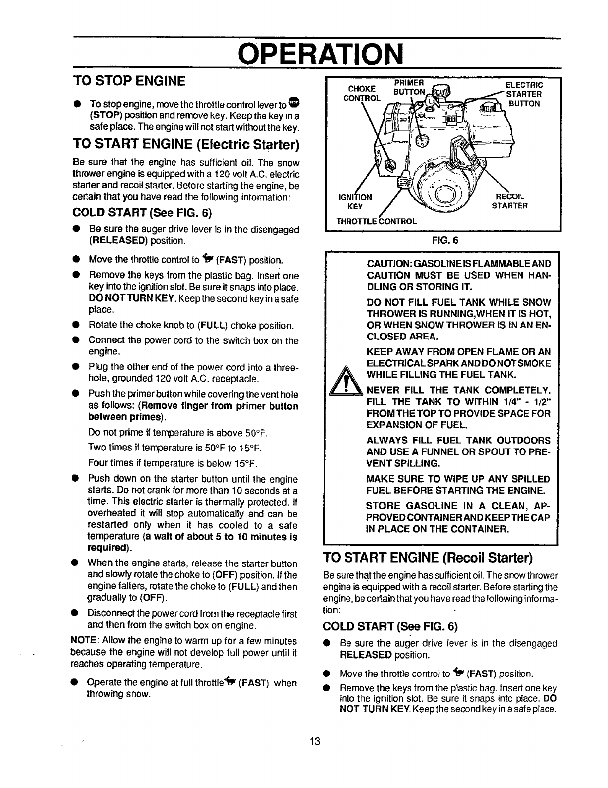
TO STOP ENGINE
• To stopengine, move the throttlecontrolleverto_I
(STOP) positionandremove key. Keep the key ina
safe place. The enginewillnotstartwithoutthekey.
TO START ENGINE (Electric Starter)
Be sure that the engine has sufficient oil. The snow
thrower engine is equipped with a 120 volt A.C. electric
starter and recoil starter. Before starting the engine, be
certain that you have read the following information:
COLD START (See FIG. 6)
• Be sure the auger drive lever is in the disengaged
(RELEASED) position.
Move the throttle control to '_ (FAST) position.
Remove the keys from the plastic bag. Insert one
key intothe ignitionslot.Be sure itsnaps intoplace.
DONOT TURN KEY. Keepthe second keyinasafe
place.
Rotate the choke knob to (FULL) choke position.
Connect the power cord to the switch box on the
engine.
Plug the other end of the power cord into a three-
hole, grounded 120 volt A.C. receptacle.
Push the primer button while covering the vent hole
as follows: (Remove finger from primer button
between primes).
Do not prime if temperature isabove 50°F.
Two times if temperature is 50°F to 15°F.
Four times iftemperature is below 15°F.
Push down on the starter button untilthe engine
starts. Do not crank for morethan 10 seconds at a
time. This electric starter is thermally protected. If
overheated it will stop automatically and can be
restarted only when it has cooled to a safe
temperature (a wait of about 5 to 10 minutes is
required).
When the engine starts, release the starter button
and slowly rotate the choke to (OFF) position.Ifthe
engine falters, rotate the choke to (FULL) and then
gradually to (OFF).
Disconnect the power cord from the receptacle first
and then from the switch box on engine.
NOTE: Allow the engine to warm up for a few minutes
because the engine will not develop full power until it
reaches operatingtemperature,
• Operate the engine at full throttle_ (FAST) when
throwingsnow.
CHOKE
CONTROL
PRIMER
BU'I-I'ON
ELECTRIC
STARTER
BUTTON
\
IGNITION
KEY
THROTTLE CONTROL
FIG. 6
i
CAUTION: GASOLINE IS FLAMMABLE AND
CAUTION MUST BE USED WHEN HAN-
DLING OR STORING IT.
DO NOT FILL FUEL TANK WHILE SNOW
THROWER IS RUNNING,WHEN IT IS HOT,
OR WHEN SNOW THROWER IS IN AN EN-
CLOSED AREA.
KEEP AWAY FROM OPEN FLAME OR AN
ELECTRICAL SPARK ANDDONOT SMOKE
WHILE FILLING THE FUEL TANK.
NEVER FILL THE TANK COMPLETELY.
FILL THE TANK TO WITHIN 1/4" - 1/2"
FROM THE TOP TO PROVIDE SPACE FOR
EXPANSION OF FUEL.
ALWAYS FILL FUEL TANK OUTDOORS
AND USE A FUNNEL OR SPOUT TO PRE-
VENTSPILLING.
MAKE SURE TO WiPE UP ANY SPILLED
FUEL BEFORE STARTING THE ENGINE.
STORE GASOLINE IN A CLEAN, AP-
PROVED CONTAINER ANDKEEPTHE CAP
IN PLACE ON THE CONTAINER.
TO START ENGINE (Recoil Starter)
Be sure that the engine has sufficient oil.The snow thrower
engine is equipped with arecoil starter. Before starting the
engine, be certain thatyou have readthefollowing informa-
tion:
COLD START (See FIG. 6)
• Be sure the auger drive lever is in the disengaged
RELEASED position.
• Move the throttle control to _ (FAST) position.
• Remove the keys from the plastic bag. Insert one key
intothe ignition slot. Be sure itsnaps intoplace. DO
NOT TURN KEY. Keep the second key ina safe place.
RECOIL
STARTER
13
OPERATION
iii |1
CAUTION: NEVER RUN ENGINE
INDOORS OR IN ENCLOSED, POORLY
VENTILATED AREAS. ENGINE EXHAUST
CONTAINS CARBON MONOXIDE, AN
ODORLESS AND DEADLY GAS. KEEP
HANDS, FEET, HAIR AND LOOSE
CLOTHING AWAY FROM ANY MOVING
PARTS ON ENGINE AND SNOW
THROWER.
WARNING: TEMPERATURE OF
MUFFLER AND NEARBY AREAS MAY
EXCEED 150° F. AVOID THESE AREAS.
DO NOT ALLOW CHILDREN OR YOUNG
TEENAGERS TO OPERATE OR BE N EAR
SNOW THROWER WHILE IT IS
OPERATING.
CAUTION: DO NOT ATTEMPT TO RE-
MOVE ANY ITEM THAT MAY BECOME
LODGED IN AUGER WITHOUT TAKING
THE FOLLOWING PRECAUTIONS:
_ RELEASE AUGER DRIVE LEVER.
@ Rotatethe choke control to (FULL) choke position.
• Push the primer button while covering the vent hole
• Pulltherecoilstarterhand2erapidly.Do notallowthe
• As the engine warms up and begins to operate
NOTE: Allowthe engineto warm upfor a few minutes
because the engine will not develop full power until it
reaches operatingtemperature.
• MOVE THROTTLE LEVER TO STOP
POSITION.
• REMOVE (DO NOT TURN) IGNITION
KEY.
• DISCONNECT SPARK PLUG WIRE.
• DO NOT PLACE YOUR HANDS IN THE
AUGER OR DISCHARGE CHUTE. USE
A PRY BAR.
as follows: (Remove finger from primer button
between primes).
Do notprime iftemperatureisabove 50°F.
Two times if temperatureis50°F to 15°F.
Fourtimes iftemperature is below 15°F.
handletosnapback,butallowittorewindslowlywhile
keepinga firmholdon the starterhandle.
evenly,rotatethe choke controlslowlyto the (OFF)
position.Iftheenginefalters, returnto(FULL) choke,
then slowlymoveto the (OFF) position.
WARM START
Ifrestarting awarm engine after a short shutdown, leave
choke at (OFF) and do not push the primer button. Ifthe
engine fails to start, follow the Cold Start instructions
above.
FROZEN STARTER
If the starter is frozen and will not turn engine:
• Pull as much rope out of the starteras possible.
• Releasethe starter handle and let itsnap back
againstthe starter.
If the engine stillfails to start, repeat the two previous
steps until the engine starts. Then continue with the
directionsfor cold start.
To help prevent possible freeze-up of recoil starter and
engine controls, proceed as follows after each snow
removal job.
• With the engine running, pull the starter rope hard
with acontinuous full arm stroke three or four times.
Pulling of starter rope will produce a loud clattering
sound. This is not harmful to the engine or starter.
• With the engine not running, wipe all snow and
moisture from the carburetorcoverinareaofcontrol
levers.Alsomovethrottlecontrol, chokecontrol,and
starter handleseveral times.
SNOW THROWING TIPS
• For maximum snow thrower efficiency operate
engine at full throttle. The engine is designed to
deliver maximum performance at full throttle and
should be run at this power setting at all times.
• Most efficient snow throwing is accomplished when
the snow is removed immediatelyafter it fails.
• For complete snow removal, s_ightlyoverlap each
path previously taken.
• The snow should be discharged down wind whenever
possible.
• After the snow throwing job has been completed,
allow the engine to idle for a few minutes, which will
melt snow and accumulated ice off the engine.
Clean the snow thrower thoroughly after each use.
Remove ice and snow accumulation and all debris
fromthe entire snowthrower, and flushwith water (if
possible) to remove all salt or other chemicats. Wipe
snow thrower dry.
• Operate the engine at full throttle "iY(FAST) when
throwingsnow.
14
CUSTOMER RESPONSIBILITIES
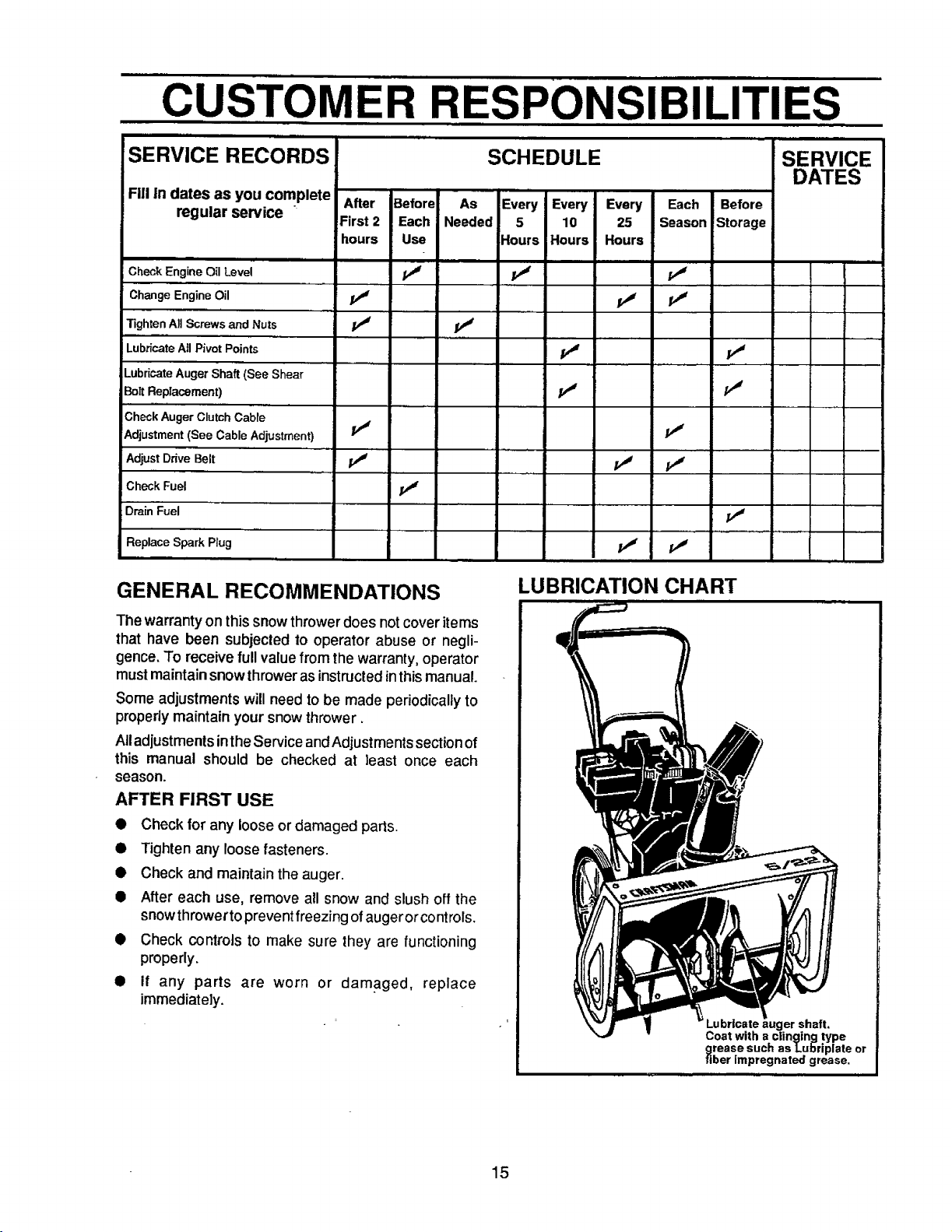
SERVICE RECORDS
Fill in dates as you complete
regular service
m
Check Engine OilLevel _ _
Change Engine Oil j_ j_ p_
Tighten All Screws and Nuts /_ pJ
Lubricate All Pivot Points _ pJ
Lubricate Auger Shaft (See Shear
Bolt Replacement) pJ PJ
Check Auger Clutch Cable
Adjustment (See Cable Adjustment) PJ PJ
Adjust Drive Belt pJ /_
Check Fuel jr_
Drain Fuel
Replace Spark Plug p,# pj
, , ......
After
First 2
hours
Before As Every Every Every Each Before
Each Needed 5 10 25 Season Storage
Use Hours Hours Hours
GENERAL RECOMMENDATIONS
SCHEDULE
iii
LUBRICATION CHART
SERVICE
DATES
The warranty on this snowthrowerdoes notcover items
that have been subjected to operator abuse or negli-
gence. To receive fullvalue fromthe warranty, operator
mustmaintainsnowthroweras instructedinthismanual.
Some adjustmentswill need tobe made periodicallyto
properlymaintain your snowthrower.
All adjustments intheService and Adjustments section of
this manual should be checked at least once each
season.
AFTER FIRST USE
• Check for any loose or damaged parts.
• Tighten any loose fasteners.
• Check and maintain the auger.
• After each use, remove all snow and slush off the
snow throwerto prevent freezing ofaugerorcontrols.
• Check controls to make sure they are functioning
properly.
• if any parts are worn or damaged, replace
immediately.
Coat with a clinging type
grease such as Lu]_riplate or
fiber impregnated grease.
shaft.
15
CUSTOMER RESPONSIBILITIES
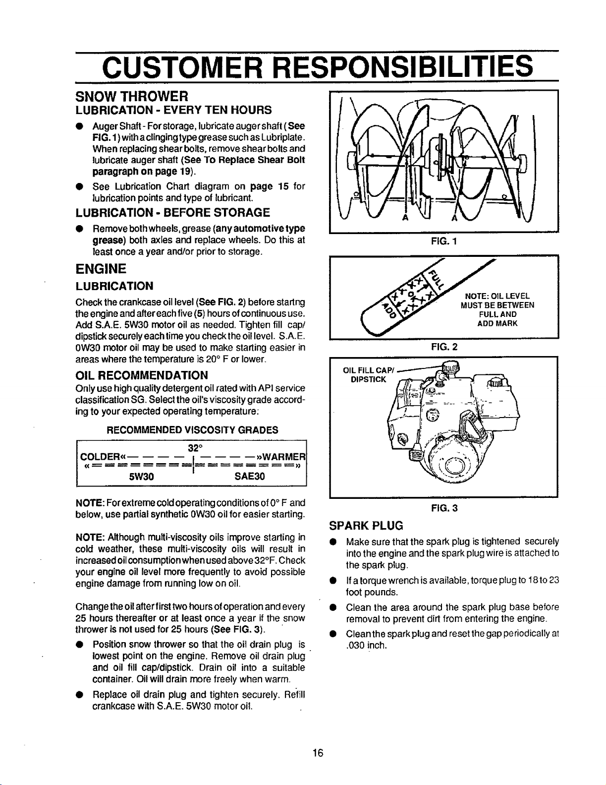
SNOW THROWER
LUBRICATION - EVERY TEN HOURS
• AugerShaft- Forstorage,lubricate augershaft (See
FIG. 1)withaclingingtype greasesuch as Lubriplate.
When replacingshearbolts,remove shear boltsand
lubricateauger shaft(See To Replace Shear Bolt
paragraph on page 19).
• See Lubrication Chart diagram on page 15 for
lubricationpointsand type of lubricant.
LUBRICATION - BEFORE STORAGE
• Removebothwheels,grease (anyautomotivetype
grease) both axles and replace wheels. Do this at
least once a year and/or priorto storage.
ENGINE
LUBRICATION
Check the crankcaseoil level(See FIG. 2) before startng
the engineand aftereachfive (5) hoursofcontinuoususe.
Add S.A.E. 5W30 motoroil as needed. Tighten fill cap/
dipsticksecurelyeachtimeyoucheckthe oil level. S.A.E.
0W30 motoroil may be used to make startingeasier in
areas where thetemperatureis 20° F or lower.
OIL RECOMMENDATION
Onlyuse highqualitydetergent oilrated withAPI service
classificationSG. Selectthe oil'sviscositygrade accord-
ingto yourexpected operatingtemperature:
RECOMMENDED VISCOSITY GRADES
/'ff',_!lr.L',,f-_°'_ MUST BE BETWEEN
[ _0 _ FULL AND
OIL RLL CAP/
DIPSTICK
A
FIG. 1
FIG, 2
1LLEV EL
ADD MARK
Co.DE.,, ,,w...E.,,
I 3io
NOTE: Forextreme coldoperatingconditionsof0° F and
below, use partialsynthetic0W30 oil for easier starting.
NOTE: Althoughmulti-viscosity oils improve starting in
cold weather, these multi-viscosity oils will result in
increasedoilconsumptionwhen usedabove32°F. Check
your engine oil level more frequently to avoid possible
engine damage from runninglow on oil.
Change theoilafterfirst twohours ofoperationand every
25 hours thereafter or at least once a year if the snow
thrower is not used for 25 hours (See FIG. 3).
• Position snow thrower so that the oit drain plug is
lowest point on the engine. Remove oil drain plug
and oil fill cap/dipstick. Drain oil into a suitable
container. Oilwilldrain more freely when warm.
• Replace oil drain plug and tighten securely. Refill
crankcase with S.A.E. 5W30 motor oil.
5W30 SAE30
FIG. 3
SPARK PLUG
• Make sure that the spark plug istightened securely
into the engine and the spark plug wire isattached to
the spark ptug.
• Ifa torquewrench is available, torque plug to I8 to 23
foot pounds.
Q Clean the area around the spark plug base before
removal to prevent dirt from entering the engine.
• Clean the spark plugand reset the gap periodically at
.030 inch.
16
SERVICE AND ADJUSTMENTS
CAUTION: ALWAYS DISCONNECT THE
SPARK PLUG WIRE AND TIE BACK
AWAY FROM THE PLUG BEFORE MAK-
ING ANY ADJUSTMENTS OR REPAIRS.
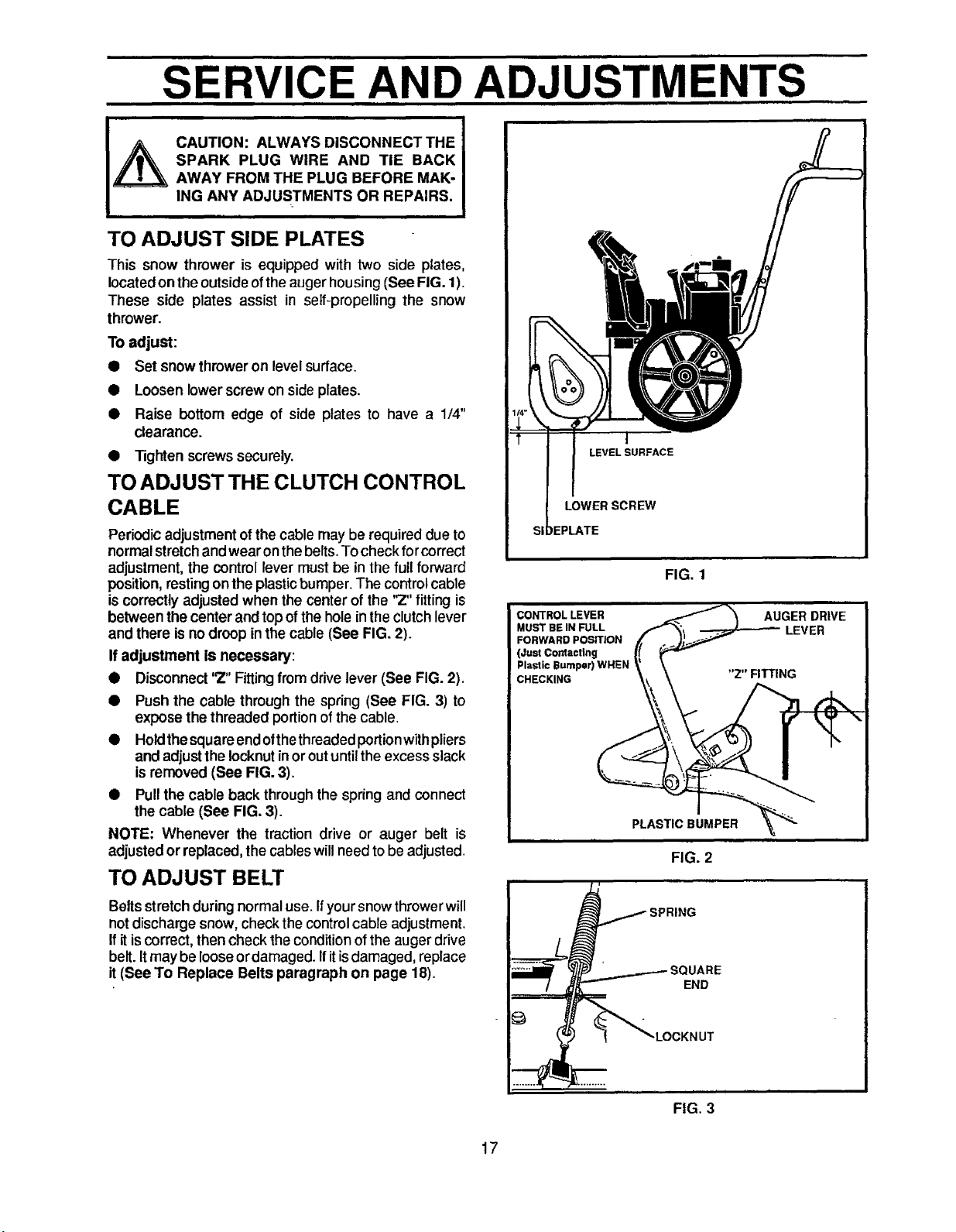
TO ADJUST SIDE PLATES
This snow thrower is equipped with two side plates,
located on the outside ofthe auger housing (See FIG. 1).
These side plates assist in self-propelling the snow
thrower.
Toadjust:
• Setsnowthroweronlevelsurface.
• Loosen lowerscrew on side plates.
• Raise bottom edge of side plates to have a 1/4"
clearance.
• Tighten screws securely.
TO ADJUST THE CLUTCH CONTROL
CABLE
Periodic adjustment of the cable may be required due to
normalstretch andwear on thebelts. Tocheck forcorrect
adjustment, the control lever must be in the full forward
position, resting on the plastic bumper. The control cable
is correctly adjusted when the center of the '_" fitting is
between the center and top of the hole in the clutch lever
and there is no droop inthe cable (See FIG. 2).
If adjustment is necessary:
• Disconnect'2" Fittingfrom drivelever (See FIG. 2).
• Push the cable through the spring (See FIG. 3) to
expose the threaded portion ofthe cable.
• Holdthesquareendofthethreadedportionwithpliers
and adjusttheIocknutinoroutuntilthe excessslack
isremoved (See FIG. 3).
• Pullthe cable back through the spring and connect
the cable (See FIG. 3).
NOTE: Whenever the traction drive or auger belt is
adjusted or replaced,the cableswill needto be adjusted.
TO ADJUST BELT
I
LEVEL SURFACE
LOWER SCREW
IEPLATE
FIG. 1
CONTROL LEVER
MUST BE IN FULL
FORWARD POSITION
(Just Cordact|ng
Plastic Bumper) WHEN
CHECKING
PLASTIC BUMPER
FIG. 2
Beltsstretch during normal use. Ifyoursnow throwerwill
not discharge snow, check the control cable adjustment.
If it is correct, then check the condition of the auger drive
belt. Itmay be loose ordamaged. Ifitisdamaged, replace
it (See To Replace Belts paragraph on page 18).
IARE
END
FIG. 3
17
i iiml i i|1
SERVICE AND ADJUSTMENTS
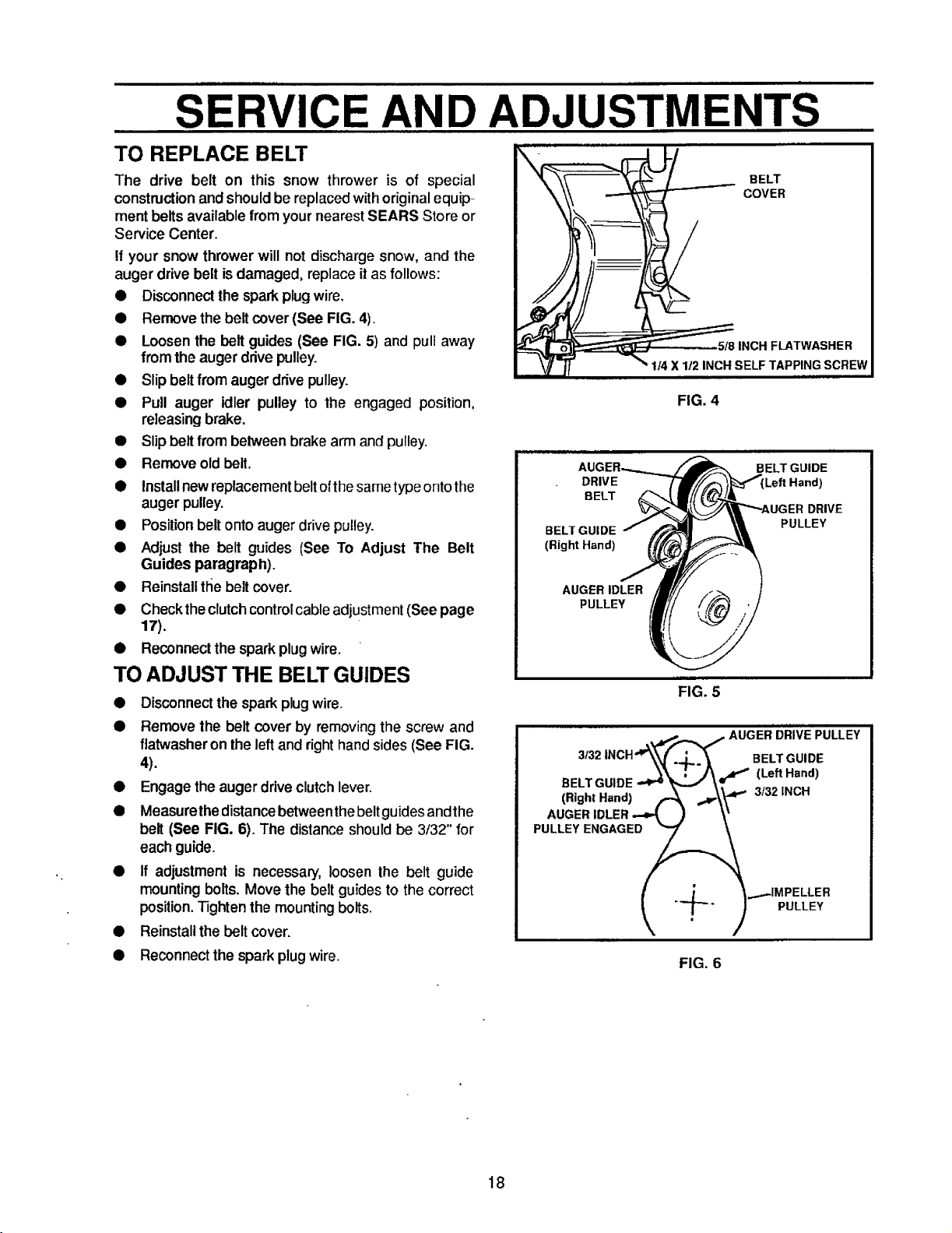
TO REPLACE BELT
The drive belt on this snow thrower is of special
constructionandshouldbe replacedwithoriginalequip-
ment belts available fromyour nearest SEARS Store or
Service Center.
If your snowthrower will not discharge snow, and the
auger drive belt isdamaged, replace itas follows:
• Disconnectthe sparkplugwire,
• Removethe belt cover(See FIG. 4).
• Loosenthe belt guides (See FIG. 5) and pull away
from the augerdrivepulley.
• Slipbeltfrom auger drive pulley.
• Pull auger idler pulley to the engaged position,
releasingbrake.
• Slipbeltfrom belween brake arm and pulley.
• Removeold belt.
• Installnewreplacementbeltofthesametypeontothe
augerpulley.
• Positionbelt onto auger drivepulley.
• Adjust the belt guides (See To Adjust The Belt
Guides paragraph).
• Reinstalltl_ebelt cover.
• Checkthe clutchcontrolcableadjustment(See page
17),
• Reconnectthe spark plugwire.
TO ADJUST THE BELT GUIDES
• Disconnectthe sparkplugwire.
• Remove the belt cover by removing the screw and
flatwasheron the left and right handsides (See FIG.
4).
• Engage the auger drive clutch lever.
• Measurethe distance between the beltguides andthe
belt (See FIG. 6). The distance should be 3/32" for
each guide.
• If adjustment is necessary, loosen the belt guide
mounting bolts. Move the belt guides to the correct
position. Tighten the mounting bolts.
• Reinstall the belt cover.
• Reconnect the spark plug wire.
FIG. 4
DRIVE
BELT
BELT GUIDE
(Right Hand)
AUGER IDLER
PULLEY
FIG. 5
AUGER DRIVE PULLEY
3f32 INCH'__ BELT GUIDE
(,.,,..a.,)A ---\V"
FIG. 6
BELT GUIDE
Left Hand)
DRIVE
PULLEY
18
 Loading...