

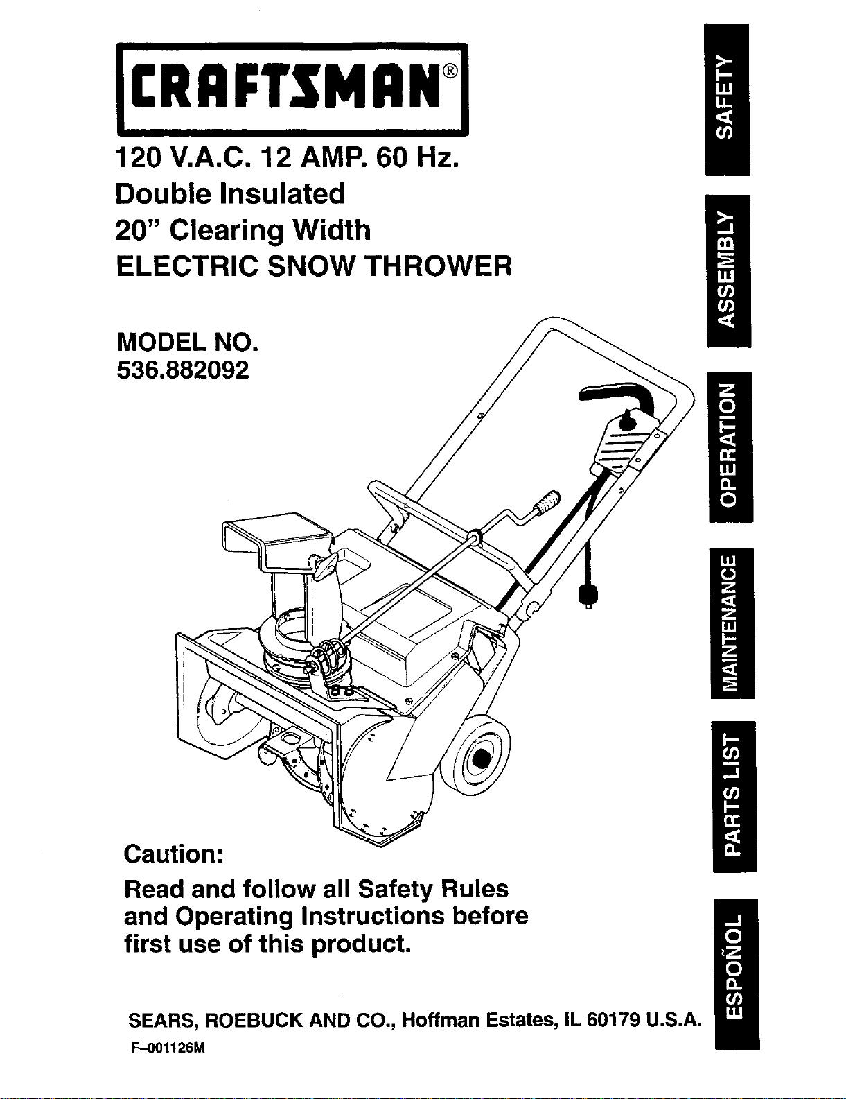
120 V.A.C. 12 AMP. 60 Hz.
Double Insulated
20" Clearing Width
ELECTRIC SNOW THROWER
MODEL NO.
536.882092
Caution:
Read and follow all Safety Rules
and Operating Instructions before
first use of this product.
SEARS, ROEBUCK AND CO., Hoffman Estates, IL 60179 U.S.A.
F-001126M
WARRANTY STATEMENT ......
SAFETY RULES ...............
ASSEMBLY ...................
OPERATION ..................
MAINTENANCE ...............
2 SERVICE AND ADJUSTMENT . . 12
3 REPAIR PARTS 16
5
7 SPANISH (ESPAI_IOL) .......... 25
11 PARTS ORDERING/SERVICE .. 40
. °..=. = = =, °.. • •
LIMITED ONE-YEAR WARRANTY ON CRAFTSMAN SNOW THROWER
For one years from the date of purchase, when this Craftsman Snow thrower is maintained,
lubricated, and tuned up according to the operating and maintenance instructions in the
owner's manual, Sears will repair, free of charge, any defect in material or workmanship.
If this Craftsman Snow thrower is used for commercial or rental purposes, this warranty ap-
plies for only 90 days from the date of purchase.
This warranty does not cover the following:
• Items which become worn during normal use such as drive belts and shear pins.
Ii,
• Repair necessary because of operator abuse or negligence, including bent crankshafts
and the failure to maintain the equipment according to the instructions contained in the
owner's manual.
WARRANTY SERVICE IS AVAILABLE BY RETURNING THE CRAFTSMAN SNOW
THROWER TO THE NEAREST SEARS SERVICE CENTER/DEPARTMENT IN THE
UNITED STATES. THIS WARRANTY APPLIES ONLY WHILE THIS PRODUCT IS IN USE
IN THE UNITED STATES.
This warranty gives you specific legal rights, and you may also have other rights which may
vary from state to state.
Sears, Roebuck and Co., D817WA, Hoffman Estates. IL 60179
GENERAL RECOMMENDATIONS
PRODUCT SPECIFICATIONS
The warranty on this snow thrower does
not cover items that have been sub-
jected to operator abuse or negligence.
Motor: 120 V.A.C., 12amps, 60Hz
Clearing Width: 20 inches
To receive full value from the warranty,
the operator must maintain the snow
Clearing Height: 8 inches
thrower as instructed in this manual.
Some adjustments will need to be made
periodically to properly maintain your
snow thrower.
All adjustments in the Service and Ad-
justments section of this manual must
be checked at least once each season.
F-001126M
2
,_ WARNING: Look for this symbol to point out important safe-
ty precautions. It means: "Attention! Become Alert! Your
Safety Is Involved."
power cord to prevent acciden-
WARNING: Always disconnect
tal starting when setting-up,
transporting, adjusting or making re-
pairs.
IMPORTANT: Safety standards require op-
erator presence controls to minimize the
risk of injury. Your snow thrower is
equipped with such controls. Do not at-
tempt to defeat the function of the opera-
tor presence control under any
circumstances.
BEFORE USE
1. Read the owner's manual carefully. Be
thoroughly familiar with the controls and
the proper use of the snow thrower. Know
how to slop the snow thrower and disen-
gage the controls quickly.
2. Do not operate the snow thrower without
wearing adequate outer garments. Wear
footwear that will improve footing on slip-
pery surfaces.
3. Keep the area of operation clear of all per-
sons, particularly small children and pets.
4. Thoroughly inspect the area where the
snow thrower is to be used and remove all
doormats, sleds, boards, wires, and other
foreign objects.
5. Use extension cords and receptacles as
specified by the manufacturer for all snow
throwers with electric ddve motors or with
factory-installed or optional starting mo-
tors.
6. Use only attachments and accessories
approved by the manufacturer of the snow
thrower. No attachments are recom-
mended for use with this unit. Any such
use might increase the risk of injury to the
operator.
7. Never operate the snow thrower without
good visibility or light. Always be sure of
your footing, and keep a firm hold on the
handles. Walk; never run.
8. This snow thrower is for use on sidewalks,
driveways, and other ground level sur-
faces. CAUTION: should be exercised
while using on steep sloping surfaces. DO
NOT USE SNOW THROWER ON SUR-
FACES ABOVE GROUND LEVEL such
as roofs of residences, garages, porches
or other such structures or buildings.
F-001126M
9. Check shear bolts and other bolts fre-
quently for proper tightness to be sure the
snow thrower is in safe working condition.
10. Let engine and snow thrower adjust to
outdoor temperatures before starting to
clear snow.
equipped with a protector that
WARNING: The motor is
will disconnect power to the mo-
tor tempOrarily if the snow thrower is
overworked, and will automatically reset
as the motor cools. If the motor stops, re-
lease the control bar, disconnect the ex-
tension cord and allow the motor to cool 5
minutes before continuing operation.
OPERATING SAFETY
1. Never allow children or young teenagers
to operate the snow thrower. Keep them
away while it is operating. Never allow
adults to operate the snow thrower without
proper instruction.
2. Do not operate this machine if you are
taking drugs or other medication which
can cause drowsiness or affect your ability
to operate this machine.
3. Do not use this machine if you are mental-
ly or physically unable to operate this ma-
chine safely.
4. Always wear safety glasses or eye shields
during operation or while performing an
adjustment or repair to protect your eyes
from foreign objects that may be thrown
from the snow thrower.
5. Always dress properly. Do not ware loose
clothing or jewelry. They can be caught in
moving parts.
6. Do not put hands or feet near or under ro-
tating parts. Keep clear of the discharge
opening at all times.
7. Exercise extreme caution when operating
on or crossing gravel drives, walks, or
roads to avoid slipping or falling, especial-
ly when operating in reverse or backing
up. Stay alert for hidden hazards or traffic.
8. Do not clear snow across the face of
slopes. Exercise caution when changing
direction on slopes. Do not attempt to
clear steep slopes.
9. Never operate the snow thrower without
proper guards, plates, or other safety pro-
tective devices in place.
10. Operation of the snow thrower in the hand
hold position is unsafe, except in accor-
3
dancewiththe special instructions for
such use provided in this manual.
11. Never operate the snow thrower near
glass enclosures, automobiles, window
wells, drop--offs, and the like without prop-
er adjustment of the snow discharge
angle. Keep children and pets away.
12. Never operate the snow thrower on grav-
eled surface unless the snow thrower is
adjusted for such a surface in accordance
with this manual. See Operating Tips in
the Operation section of this manual.
13. Never operate the snow thrower at high
transport speeds on slippery surfaces.
Look behind and use care when backing.
14. Never direct discharge at bystanders or
allow anyone in front of the snow thrower.
15. Take all possible precautions when leav-
ing the snow thrower unattended. Disen-
gage the auger/impeller, and remove key.
16. To prevent accidental starting do not carry
plugged-in snow thrower with finger on
switch. Be sure switch is off when plug-
ging in.
17. If cord is d_maged in any manner while
plugged in, pull extension cord from wall
receptacle.
18. Do riot abuse cord. Never carry snow
thrower by cord or yank it to disconnect
from receptacle. Keep cord from heat, oil,
and sharp edges.
19. Do not overload the machine capacity by
attempting to clear snow at too fast a rate.
20. Do not force snow thrower. It will perform
better and safer at the rate for which it
was designed.
21. Do not over reach. Keep proper footing
and balance at all times.
shock, use U.L. listed two con-
WARNING: To prevent electric
ductor extension cord suitable
for outdoor use in cold weather. Exten-
sion cord should be no longer than 100
feet. See chart in Operation section for
recommended extension cords.
22. To prevent accidental disconnection of ex-
tension cord from control switch during
operation, loop extension cord through
strain relief clip on control switch as
shown in the assembly section of this
manual.
REPAIR/ADJUSTMENTS SAFETY
1. After striking a foreign object, stop the en-
gine (motor), disconnect the cord on elec-
tric motors, thoroughly inspect the snow
thoroughly inspect the snow thrower for
any damage, and repair the damage be-
fore restarting and operating the snow
thrower.
2. If snow thrower should start to vibrate ab-
normally, stop engine (motor) and check
immediately for the cause. Vibration is
generally a warning of trouble.
3. Stop the engine (motor) whenever you
leave the operating position. Also, discon-
nect the power cord before unclogging
the auger/impeller housing or discharge
chute, and when making any repairs, ad-
justments, or inspections to prevent acci-
dental starting.
4. When cleaning, repairing, or inspecting,
make certain the auger/impeller and all
moving parts have stopped. Disconnect
the power cord for service.
5. Never attempt to make any adjustments
while the engine (motor) is running (ex-
cept when specifically recommended by
the manufacturer).
6. Maintain or replace safety and instruction
labels, as necessary.
7. When servicing, use only identical re-
placement parts. Replace or repair dam-
aged cords.
8. Maintain snow throwers with care. Follow
instructions and changing accessories.
9. Run the snow thrower a few minutes after
throwing snow to prevent freeze-up of the
auger/impeller.
SAFE STORAGE
1. Always refer to the owner's manual in-
structions for important details if the snow
thrower is to be stored for an extended
period.
2. Store snow thrower indoors when not in
use. Snow throwers should be stored in-
doors in a dry, locked-up place out of
reach of children.
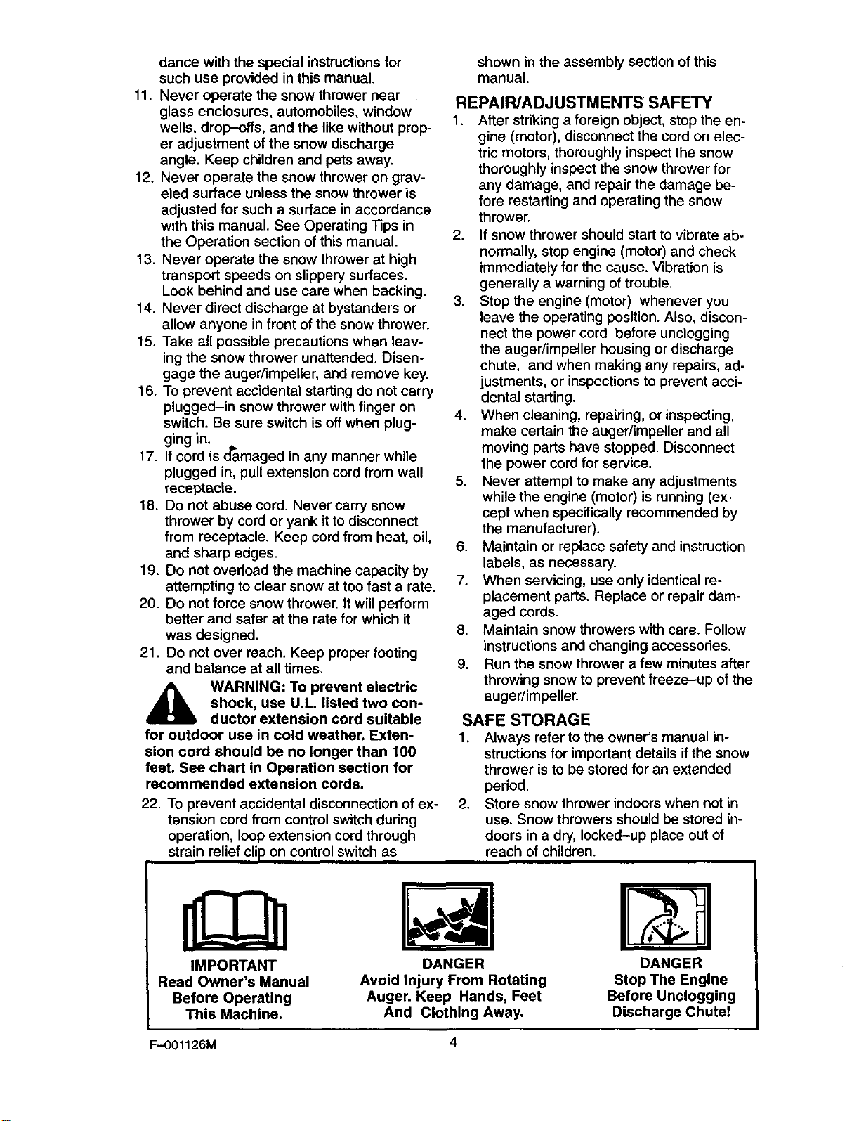
IMPORTANT
Read Owner's Manual
Before Operating
This Machine.
F-OO1126M 4
Avoid Injury From Rotating
Auger. Keep Hands, Feet
DANGER
And Clothing Away.
DANGER
Stop The Engine
Before Unclogging
Discharge Chute!
ASSEMBLY
CONTENTS OF PARTS BAG
1 - Owner's Manual
1 - Warranty Card
1 - Parts Bag
(Not shown actual size)
1 - Key
glasses or eye shields while as-
WARNING: Always wear safety
sembling snow thrower.
TOOLS REQUIRED FOR ASSEMBLY
1 - Knife to cut carton.
1- Pliers
The figure below shows the snow thrower
completely assembled.
References to the right or left hand side of
the snow thrower are from the viewpoint of
the operator's position behind the unit.
TO REMOVE SNOW THROWER
FROM CARTON
1. Remove the inserts positioned around
the unit and the packing material.
2. Cut down all four corners of the carton
and lay the panels flat.
3. Pull snow thrower out of the carton.
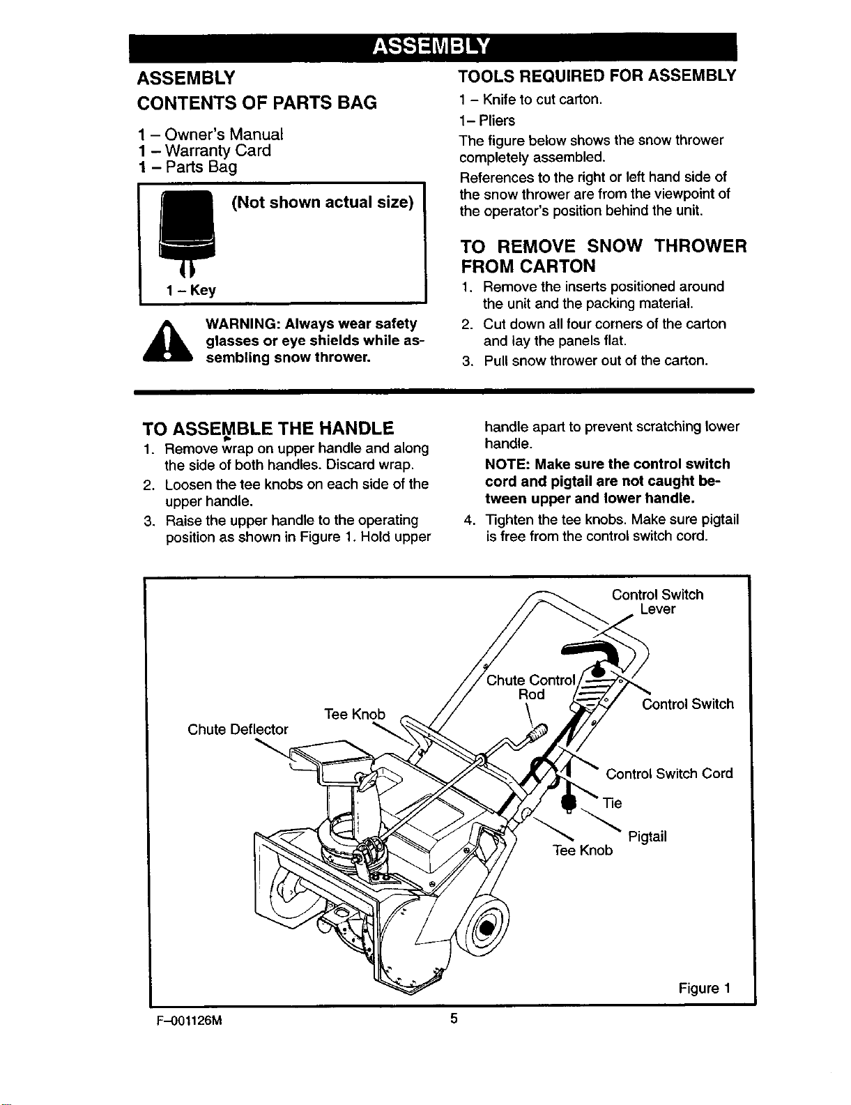
TO ASSEMBLE THE HANDLE
1. Remove wrap on upper handle and along
the side of both handles. Discard wrap.
2. Loosen the tee knobs on each side of the
upper handle.
3. Raise the upper handle to the operating
position as shown in Figure 1. Hold upper
Tee Knob
Chute Deflector
handle apart to prevent scratching lower
handle.
NOTE: Make sure the control switch
cord and pigtail are not caught be-
tween upper and lower handle.
4. Tighten the tee knobs. Make sure pigtail
is free from the control switch cord.
Control Switch
Lever
Control Switch
Control Switch Cord
Tie
F-001126M 5
Tee Knob
Pigtail
Figure 1
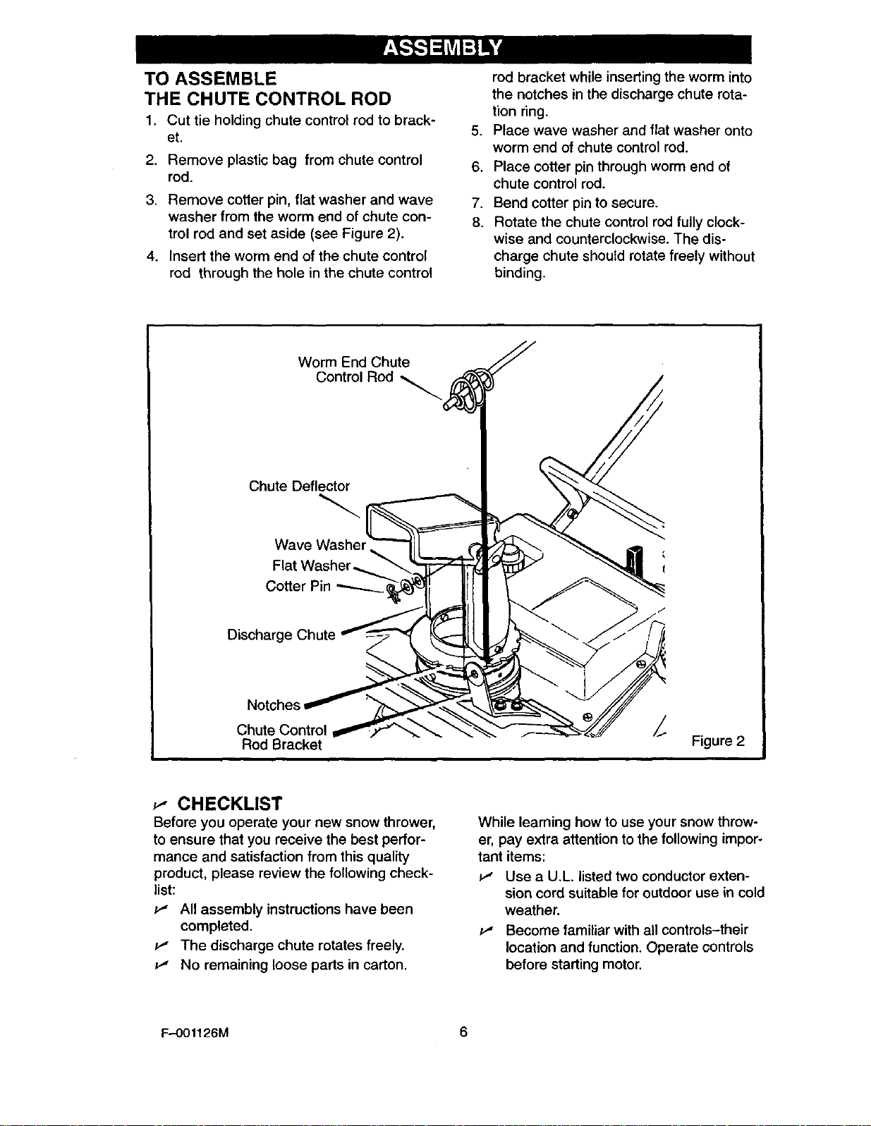
TO ASSEMBLE
THE CHUTE CONTROL ROD
1. Cut tie holding chute control rod to brack-
et.
2. Remove plastic bag from chute control
rod.
3. Remove cotter pin, flat washer and wave
washer from the worm end of chute con-
trol rod and set aside (see Figure 2).
4. Insert the worm end of the chute control
rod through the hole in the chute control
Worm End Chute
Control Rod
Chute Deflector
rod bracket while inserting the worm into
the notches in the discharge chute rota-
tion ring.
,
Place wave washer and flat washer onto
worm end of chute control rod.
6.
Place cotter pin through worm end of
chute control rod,
7.
Bend cotter pin to secure.
8.
Rotate the chute control rod fully clock-
wise and counterclockwise. The dis-
charge chute should rotate freely without
binding.
Wave Washer
Flat Washer
Discharge
Notches
Chute Control i
Rod Bracket
_,- CHECKLIST
Before you operate your new snow thrower,
to ensure that you receive the best perfor-
mance and satisfaction from this quality
product, please review the following check-
list:
P" All assembly instructions have been
completed.
v' The discharge chute rotates freely.
No remaining loose parts in carton.
Figure 2
While learning how to use your snow throw-
er, pay extra attention to the following impor-
tant items:
P" Use a U.L. listed two conductor exten-
sion cord suitable for outdoor use in cold
weather.
P" Become familiar with all controls-their
location and function, Operate controls
before starting motor.
F-001126M 6
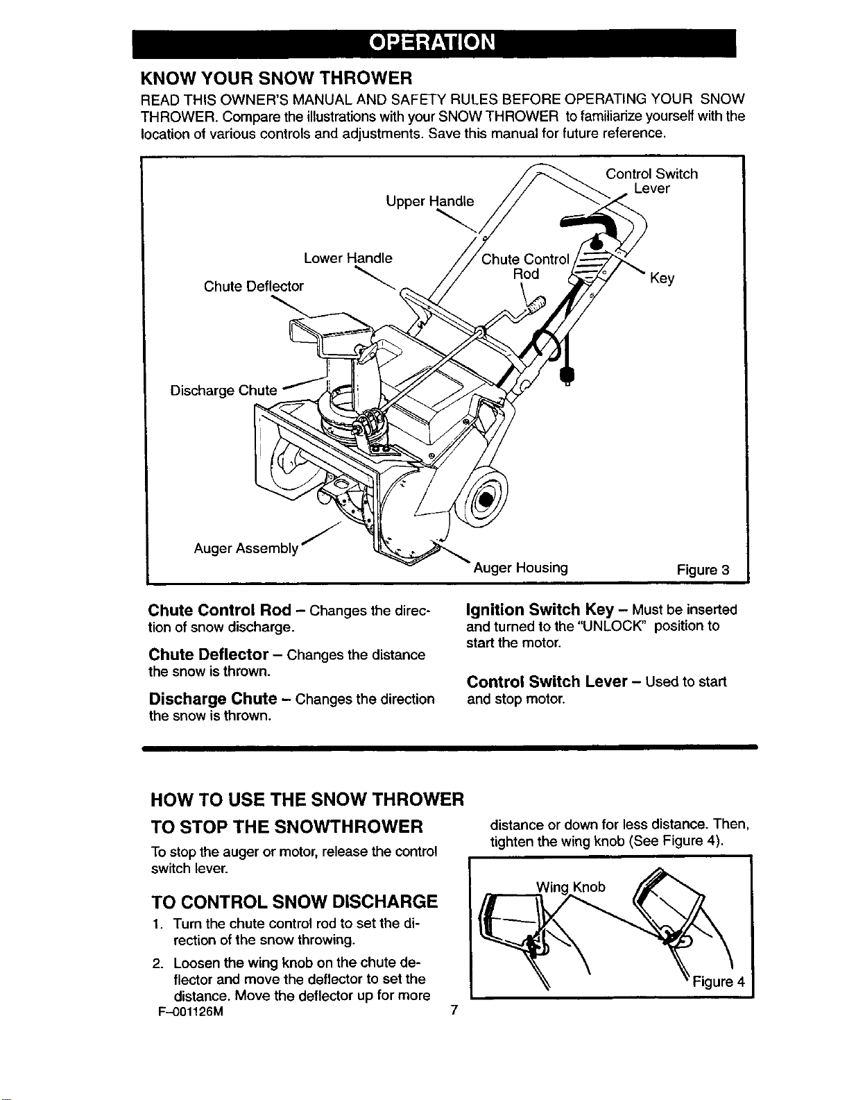
KNOW YOUR SNOW THROWER
READ THIS OWNER'S MANUAL AND SAFETY RULES BEFORE OPERATING YOUR SNOW
THROWER. Compare the illustrations with your SNOW THROWER to familiarize yourself with the
location of various controls and adjustments. Save this manual for future reference.
Control Switch
Lever
Upper Handle
Lower Handle
Chute Deflector
Auger Assembly j
LL_ Auger Housing Figure 3
Chute Control Rod - Changes the direc-
tion of snow discharge.
Chute Deflector - Changes the distance
the snow isthrown.
Discharge Chute - Changes the direction
the snow isthrown.
HOW TO USE THE SNOW THROWER
TO STOP THE SNOWTHROWER
To stop the auger or motor, release the control
switch lever.
TO CONTROL SNOW DISCHARGE
1. Turn the chute control rod to set the di-
rection of the snow throwing.
2. Loosen the wing knob on the chute de-
flector and move the deflector to set the
distance. Move the deflector up for more
F--001126M
Ignition Switch Key - Must be inserted
and turned to the "UNLOCK" position to
start the motor.
Control Switch Lever - Used to start
and stop motor.
distance or down for less distance. Then,
tighten the wing knob (See Figure 4).
Knob
7
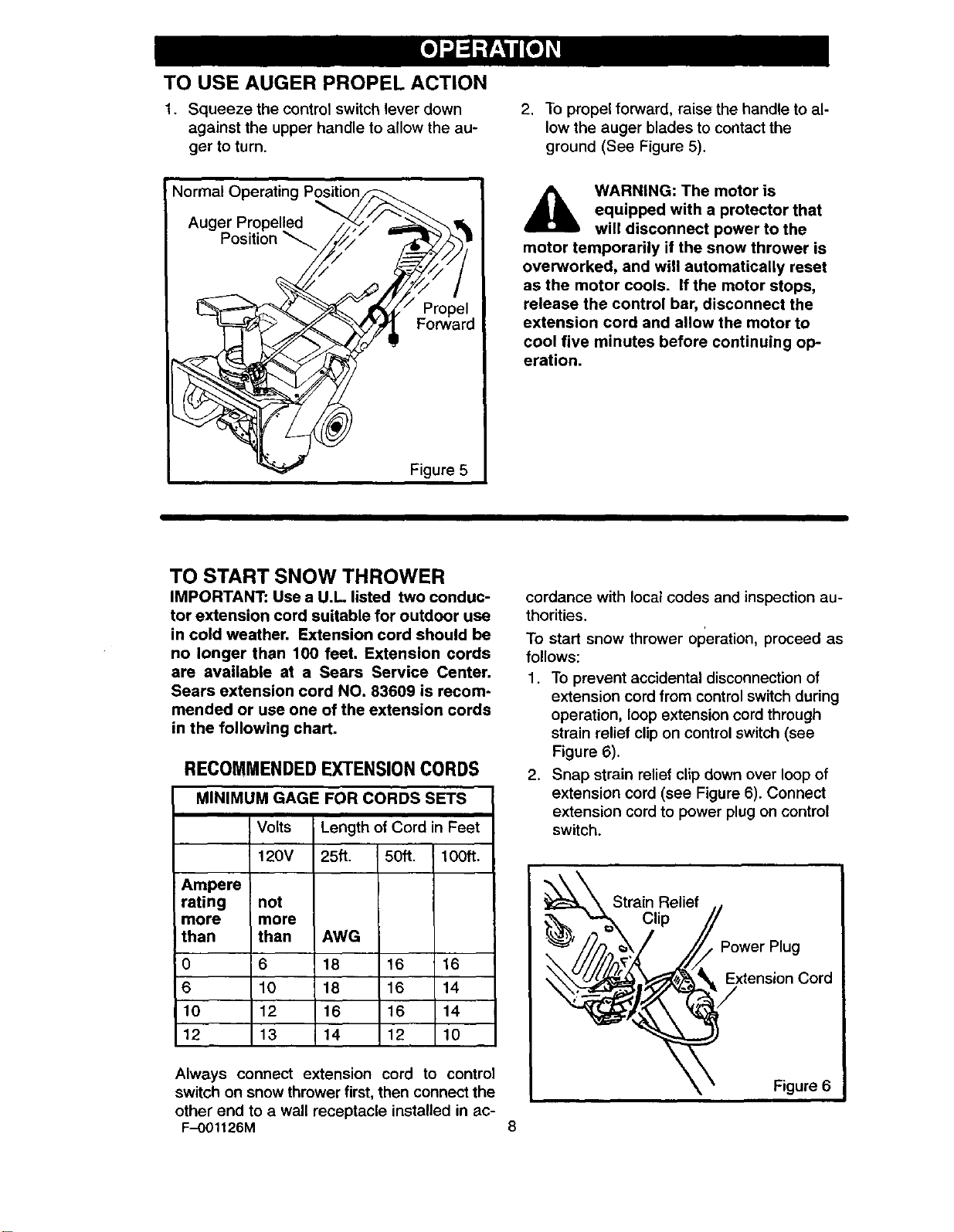
TO USE AUGER PROPEL ACTION
1. Squeeze the control switch lever down
against the upper handle to allow the au-
ger to turn.
2. To propel forward, raise the handle to al-
low the auger blades to contact the
ground (See Figure 5).
equipped with a protector that
WARNING: The motor is
will disconnect power to the
motor temporarily if the snow thrower is
overworked, and will automatically reset
as the motor cools. If the motor stops,
release the control bar, disconnect the
extension cord and allow the motor to
cool five minutes before continuing op-
eration.
TO START SNOW THROWER
IMPORTANT: Use a U.L listed two conduc-
tor extension cord suitable for outdoor use
in cold weather. Extension cord should be
no longer than 100 feet. Extension cords
are available at a Sears Service Center.
Sears extension cord NO. 83609 is recom-
mended or use one of the extension cords
in the following chart.
RECOMMENDEDEXTENSIONCORDS
MINIMUM GAGE FOR CORDS SETS
Volts Length of Cord in Feet
120V 25ft. 50ft. lOOft.
Ampere
rating
more
than
0
6
10
12
not
more
than AWG
6 18 16 16
10 18 16 14
12 16 16 14
13 14 12 10
cordance with local codes and inspection au-
thorities.
To start snow thrower operation, proceed as
follows:
1. To prevent accidental disconnection of
extension cord from control switch during
operation, loop extension cord through
strain relief clip on control switch (see
Figure 6).
2. Snap strain relief clip down over loop of
extension cord (see Figure 6). Connect
extension cord to power plug on control
switch.
___ Strain Relief .
c,p II
Always connect extension cord to control
switch on snow thrower first, then connect the
other end to a wall receptacle installed in ac-
F-OOl126M

3. To operate snow thrower turn key (clock-
wise) and hold in UNLOCKED position
while pulling control switch lever toward
handle. Hold control switch lever and re-
lease key (see Figure 7).
Operating Position
Control Switch
Lever
_/ Released
Position
Key
Control
Switch
Figure 7
NOTE: Keep the second key (found in plas-
tic bag) in a safe place.
4. To stop snow thrower, release lever on
upper handle.
TO STOP SNOW THROWER
1, Release control switch lever on upper
handle.
2. Disconnect extension cord from wall re-
ceptacle first, then from power cord on
control switch.
3. Remove key when not in use.
,_ WARNING: If snow thrower fre-
with higher rated fuse without consulting
the power company.
quently trips circuit breaker or
blows fuses, DO NOT replace
SNOW THROWING TIPS
This snow thrower will propel itself for-
ward when the handle is raised enough
to cause the auger blades to contact the
ground. The auger will stop when control
switch lever is released.
For most efficient snow throwing, turn the
discharge chute deflector to throw snow
downwind, and slightly overlap each
swath. In light snow take up to a full cut
and in heavy snow take less than a full
cut.
The distance snow will be discharged
can be adjusted by moving the discharge
chute deflector. Raise the deflector for
more distance or lower the deflector for
less distance.
In windy conditions, lower the chute de-
flector to direct discharged snow close to
the ground where it is less likely to blow
into unwanted areas.
Keep the area to be cleared free of •
stones, toys and other foreign objects for
F-O01126M 9
safety and to prevent damage to the
snow thrower.
Do not use the auger propelling feature
when clearing gravel or crushed rock
driveways. Move the handle down to
raise the auger slightly.
The allowable forward speed of the snow
thrower is dependent on the depth and
weight of the snow. Experience will es-
tablish the most effective method of using
the snow thrower under different condi-
tions.
DRY AND AVERAGE SNOW
Snow up to eight inch depth can be re-
moved rapidly and easily by walking at a
moderate rate. For snow or drifts of a
greater depth you may find it desirable to
slow your pace to allow the discharge
chute to dispose of the snow as rapidly
as the auger receives the snow.
Plan to have the snow discharged in the
direction the wind is blowing.

hind snow thrower (operator's
WARNING: Always stand be-
position) when starting motor.
Do Not put hands, feet, hair or loose
clothing on near the discharge chute de-
flector or auger housing while the motor
is running.
gravel, rocks or other debris, if
WARNING: Objects such as
struck by the auger, may be
thrown with sufficient force to cause per-
sonal injury or property damage.
WET PACKED SNOW
Move slowly into snow of this condition. The
greater the depth, the slower you should go.
When it appears that the wet, packed snow
is causing the auger to slow down and the
chute to clog, back off and begin a series of
short jabs into the snow. These short back
and forth, 4 to 6 inch, jabbing motions will
"belch" the snow from the chute.
SNOW BANKS AND DRIFTS
in snow of greater depth than the unit, use
the "jabbing" technique described above.
Turn the discharge chute away from the
snow bank. More time will be required to re-
move snow of this type than level snow.
F-O01126M 10

CUSTOMER RESPONSIBILITIES
SERVICERECORDS After
Fillin datesasyou 12
completeregularservice. Hours
Tighten All Screws & Nuts ",,J
Check Drive Belts
Lubricate Chute Control Flange
First
As
Needed
Before
Storage
Begin
Each
Season
SERVICEDATES
GENERAL RECOMMENDATIONS
The warranty on this snow thrower does not
cover items that have been subjected to op-
erator abuse or negligence. To receive full
value from the warranty, the operator must
maintain the snow thrower as instructed in
this manual
Some adjustments will need to be made pe-
riodically to properly maintain your snow
thrower.
All adjustments in the Service and Adjust-
ments section of this manual should be
checked at least once each season.
AFTER FIRST USE
• Check for any loose or damaged parts
after each use.
LUBRICATION CHART
• Tighten any loose fasteners.
AFTER EACH USE
Run the machine to clear the auger of
snow.
Remove all snow and slush from the
snow thrower to prevent freezing of au-
ger or controls.
LUBRICATION - AS REQUIRED
Lubricate the flange on the discharge
chute before storage.
See Lubrication Chart diagram for lu-
brication points and type of lubricant.
F-001126M 11
Lubricate chute control flange.
Remove discharge chute and
coat flange with a clinging type
grease such as Lubriplate.
Figure 8

TO ADJUST
THE CHUTE CRANK ASSEMBLY
If you cannot rotate the chute crank fully to
the left and to the right, you need to adjust
the chute crank (see Figure 9).
1, Loosen both 1/2" nuts, using 1/2"
wrenches, on the crank adjusting brack-
et.
2. Swivel the crank adjusting bracket to al-
low 1/8" clearance between the notch in
the flange and the outer diameter of the
worm.
3. Once this clearance is set, tighten the
nuts.
TO REMOVE BELT COVER
1. Remove the belt cover (see Figure 10) by
removing the ten screws. There are five
screws on the front of the belt cover, two
screws on the top of the belt cover, and
three scrp_wson the bottom of the belt
Motor Pulley
Idler Pulle,
Auger
Housing
Auger Pulley
Short Screw Location
cover. The front screw on the bottom of
the belt cover is shorter than the rear and
top screws).
2. Pull the belt cover away from the snow
thrower.
Top Belt Cover
Belt Cover
Figure 10
TO ADJUST THE DRIVE BELT
If the motor drive pulley and the auger drive
pulley are not aligned properly, excessive
belt wear will occur. To check the pulley
alignment, proceed as follows:
1. Remove the belt cover (see "To Remove
Belt Cover").
2. Place a straight edge approximately 16"
tong across the large auger pulley, con-
tacting two points and extending to the
motor pulley (see Figure 11). The outside
of the motor pulley must be flush with the
straight edge. If the pulleys are aligned,
skip to the last step).
F-OO1126M
12

TO ADJUST THE MOTOR PULLEY
1. Loosen the two set screws on the motor
pulley.
2. Slide the motor pulley in or out on the
shaft until the pulley is flush with the
straight edge (see Figure 11).
3. Tighten the two set screws on the motor
pulley.
4. Reinstall belt cover. Make sure the short-
er screw is in the front position (see
Figure 10).
5. If the drive belt is damaged or worn ex-
cessively, replace it with a new belt.
NOTE: When servicing use only identical
replacement parts. If extension cord is
damaged, in any manner, replace or re-
pair cord.
TO REPLACE THE DRIVE BELT
The drive belt on this unit is of special
construction and must be replaced with the
same type belt available at your nearest au-
thorized service center.
1. Remove the belt cover.
2. Carefully lift idler pulley to release pres-
sure on belt (see Figure 12).
3. Remove _ld belt.
4. Replace with new belt with belt ribs
down.
5. Release idler pulley.
6. Make sure the belt is seated properly.
7. Check the drive belt adjustment (see "To
Adjust the Drive Belt".
8. Reinstall belt cover. Make sure the short-
er screw is in the front position (see
Figure 10).
TO REPLACETHEAUGER
1. Remove the belt cover (see "To Remove
Belt Cover").
2. Remove the drive belt (see "To Replace
The Drive Belt").
3. Remove the auger pulley (see Figure 13)
from the auger shaft (threads are left
hand; turn clockwise to remove). Place a
piece of wood (2x4) on the center paddle
area to secure auger to keep from turn-
ing.
4. Remove the bearing assembly from the
left frame of snow thrower by removing
the two nuts on the inside of housing.
5. Slide the auger assembly out of the bear-
ing assembly on the right side of the
snow thrower.
Motor Pu]le
Idler Pulley
Drive Belt
Auger Pulley
Figure 12
7. Install the new auger assembly in reverse
order of removal.
NOTE: Check the drive belt adjustment
before installing the belt cover (see "To
Adjust the Drive Belt").
6. Tip the auger assembly enough to allow it
to slide out of the auger housing.
F-001126M
13

MOTOR SERVICE
Motor repairs and adjustments should be
done by technicians trained to work on snow
thrower type motors. Take your snow throw-
er to an Authorized Sears Service Center for
repair and adjustment.
SNOW THROWER STORAGE
Thoroughly clean the snow thrower.
Lubricate all the lubrication points (see
the Maintenance section).
Be sure _at all nuts, bolts and screws
are securely fastened. Inspect all visible
moving parts for damage, breakage and
wear. Replace if necessary.
Touch up all rusted or chipped paint sur-
faces; sand lightly before painting.
Cover the bare metal parts of the blower
housing and auger with rust preventative,
such as a spray lubricant.
Store the snow thrower indoors in a
clean, dry, locked-up place out of reach
of children.
Store the extension cord with the snow
thrower to prevent misplacement.
Inspect the snow thrower thoroughly for
worn, loose or damaged parts. Make all
necessary repairs before storing snow
thrower.
Inspect extension cord thoroughly for
signs of excess wear or damage. If worn
or damaged, replace with a U,L. listed
cord suitable for outdoor use in cold
weather,
NOTE: A yearly checkup or tune-up at a
Sears Authorized Service Center is a
good way of ensuring that your snow
thrower will provide maximum perfor-
mance for the next season.
F-OO1126M 14

TROUBLE
CAUSE
CORRECTION
Motor runs erratically
Excessive vibration
Unit fails to propel itself
Unit fails to discharge
snow
Damaged motor
Obstruction in auger
Loose parts
Damaged auger
Drive belt loose or damaged
Worm auger assembly
Auger drive belt loose or
damaged
Have the unit serviced by a
competent repairman.
Remove obstruction.
Clean auger housing.
Clean ice and snow from
discharge chute.
Stop motor immediately and
unplug power cord.
Tighten all bolts and make all
necessary repairs. If
vibration continues, have the
unit serviced by a
competent repairman.
Repair or replace auger
assembly.
Replace drive belt.
Replace auger assembly.
Replace if damaged.
Motor stops
Discharge chute clogged
Foreign object lodged in
auger
Snow Thrower is overworked
Stop motor immediately and
unplug power cord.
Clean discharge chute and
inside of auger housing.
Stop motor immediately and
unplug power cord.
Remove object from auger.
The motor is equipped with a
)rotector that will disconnect
)ower to the motor
temporarily if the snow
thrower is overworked, and
will automatically reset as the
motor cools. If the motor
stops, release the control
bar, disconnect the extension
cord and allow the motor to
cool 5 minutes before
continuing operation. Ifthis
happens often take your
snow thrower to an
Authorized Sears Service
Center for repair and
adjustment.
F_01126M 15

CRAFTSMAN20"ELECTRICSNOWTHROWER536.882092
MOTOR ASSEMBLY
17 27
31
54 33
54 52
45
10-2
46
10-1
3O
F-OO1126M 16
DETAIL 'A'
342691

CRAFTSMAN 20" ELECTRIC SNOW THROWER 536.882092
MOTOR ASSEMBLY
Key No. Description Part No.
10 MOTOR, ELECTRIC 760912
10-1 BRUSH CAP 761142
10-2 BRUSH CUT-OUT ASSY, 761143
10-3 BRUSH ASSY. 761144
10-.-4 RECTIFIER 761146
10-5 SCREW, 10-24 761145
11 NUT RETAINER 710288
12 BOLT, 5/16-18 x .75 340720
13 PLASTIC WASHER 6711
14 TUBE, INSULATOR 761203
15 BOLT, 5/16-18 x 1.00 3316
17 NUT,#10-24 312300
18 FLATWASH ER 71067
19 NUT, 1/4-20 782585
20 BRACKET, UPPER MOTOR MT. 760932-853
•'21 BRACKET, LOWER MOTOR MT. 760931-853
22 FLATWASHER 583372
23 SCREW, 1/4-20 x 1.00 180022
24 INSULATOR, MOTOR 760934
25 INSULATOR WASHER 760933
26 FLATWASHER 71071
27 NUT, 5/16-18 71038
28 BRACE, MOTOR 760984-853
29 SHOULDER WASHER 583371
30 PULLEY, MOTOR 760981
31 SCREW, 1/4-20 x .38 102570
32 SQUARE KEY 71095
33 BELT 760976
40 IDLER BRACKET 583395
41 SCREW, 3/8-16 x 1.50 710082
42 IDLER PULLEY 583391
44 NUT, 3/8-16 590
45 FLATWASHER 71072
46 SCREW, 5/16-18 x .75 313676
47 FLATWASHER 71071
48 SPACER, SLEEVE 53794
49 NUT, 5/16-18 71391
50 IDLER SPRING 760988
52 SCREW, 1/4-20 x 1.25 308231
54 NUT. 1/4-20 71034
-- MANUAL, OWNER'S F-001026M
F-001126M 17

CRAFTSMAN20"ELECTRICSNOWTHROWER536.882092
FRAME ASSEMBLY
_115 9
Key
NO.
80 FRAME, SIDE RH 333769-853
81 FRAME, SIDE LH 333767
90 CHANNEL SUPPORT 760982
91 SCREW, 1/4-20 x 2.00 180044
92 NUT, 1/4-20 782585
115 PLATE, SUPPORT 334856
92---_Description
--92 313936
WHEEL ASSEMBLY
650
Key
No. Description Part No.
650 AXLE, 7 x 1,5 313678
651 FLATVVASHER 583409
660 TIRE & RIM 577036
661 FLA'I-WASH ER 583409
662 E RING 577598
F-001126M 18
651 660
661
334309

CRAFTSMAN20"ELECTRICSNOWTHROWER536.882092
DISCHARGE CHUTE ASSEMBLY
591
591
605
604
590
j606
\
592
ITEM
HOUSING
Key No. Description
580 RING, CHUTE
581 SCREW, 1/4-20 x .50
582 GUIDE, CHUTE
590 LOWER CHUTE
591 SCREW, 1/4-20 x .50
592 NUT, 1/4-20
600 UPPER CHUTE
601 WIRE HINGE
602 BOLT, 5/16-18 x 1.25
603 FLATWASHER
604 T KNOB
605 NUT, 5/16-18
606 SCREW, 5/16-18 x .756
607 FLA"RNASH ER
608 NUT, 5/16-18
F-001126M 19
313939
Part No.
314239
711752
577021
334234
313686
302635
325847
308931
302843
71071
57171
71037
578088
71071
71391

511
CRAFTSMAN20"ELECTRICSNOWTHROWER536.882092
AUGER HOUSING ASSEMBLY
512
483
481
480
532
540
520-2
520-8
520
Key
No. Description
480 HOUSING ASSEMBLY
481 SCREW, 1/4-20x.75
482 FLATWASHER
483 NUT, 1/4-20
486 SCREW, 1/4-20 x.63
487 BRACKET, STOP
488 FLATWASHER
489 NUT,I/4-20
490 SCRAPER BAR
491 RIVET
492 SCREW, 1/4-20x .75
493 NUT, 1/4-20
510 FLANGE BEARING
511 SCREW, 1/4-20x1.00
512 FLATWASHER
F-001126M
Part Key
No. No.
330312 513
302628 520
71067 520-2
73826 520-6
579052 520-8
331126 520-10
331211 530
302635 531
55323 532
577707 533
302628 534
302635 539
577023 540
710263 541
71067
20
492
342670
Part
Description No.
NUT, 1/4-20 302635
AUGER ASSEMBLY 302783
AUGER BLADE 302565
RIVET 49838
CENTER BLADE 335992
BLADE SU PPORT 302552
BEARING ASSEMBLY 583459
BEARING RETAINER 334287
SCREW, 1/4-20x5/8 579052
FLA'I'WASH ER 71067
NUT, 1/4-20 73826
FLA'INMASHER 40677
SPACER, SLEEVE 578101
PULLEY, POLY V 583363

CRAFTSMAN 20" ELECTRIC SNOWTHROWER536.882092
HANDLE ASSEMBLY
756
757
764
Key
No. Description Part No,
750 HANDLE, LOWER 313487-853
751 SCREW 313674
752 FLATWASHER 71067
753 NUT, 1/4-20 782585
755 ASSY, SWITCH BOX 342757
756 SCREW, 10-24 581060
757 NUT, #10-24 71055
F-O01126M
750
762
753
342561
Key
No. Description Part No.
758 KEY, SWITCH BOX 583356
760 UPPER HANDLE 761117
762 BOLT 337584
763 WASHER, FORMED 311936
764 T KNOB 57171
765 NUT, 5/16-18 71037
21

CRAFTSMAN20"ELECTRICSNOWTHROWER536.882092
BELT COVER ASSEMBLY
170
172
®
151 1 127
Key No. Description Part No.
120 BOTTOM COVER 584589
121 SCREW, 1/4-20 x 1.25 313674
122 FLATWASHER 71067
123 SCREW, 1/4-20 x 1.50 70971
124 NUT, 1/4-20 782585
126 CABRURATOR COVER 326212
127 SCREW, 1/4-14 x .75 313685
128 NUT, 1/4-10 578109
129 CABLE CLIP 583435
150 COVER, BELT 57036
151 SCREW, 10-24 x .50 12342
152 NUT, #10-24 312300
153 SCREW, 1/4-20 x .50 313686
154 FLATWASHER 71067
155 NUT, 1/4-20 578107
157 SCREW, 1/4-14 x .75 313685
159 NUT, 1/4-10 578109
170 TOP COVER 760958
171 FLArWASH ER 901736
172 RIVET 902973
174 SIDE COVER 58046
F-O01126M 22
338427

852
CRAFTSMAN20"ELECTRICSNOWTHROWER536.882092
CHUTE CONTROL ROD ASSEMBLY
z 856
853
851
_857
855
87O
ITEM
LOWER HANDLE
Key No.
F-O01126M
850
851
852
853
855
856
857
86O
861
863
864
87O
871
872
873
874
Description
ROD, ASSY UPPER CHUTE
FLATWASHER
COI-FER PIN
WASHER, CURVED SPRING
FLATWASHER
KNOB, SLEEVE
NUT, PUSH
EYE BOLT 3/8-16x2.00
GROMMET, EYE BOLT
WASHER, SPLITLOCK
NUT, 3/8-16
BRACKET, CHUTE ROTATE
BOLT, 5/16-18 x .75
FLATWASHER
WASHER, SPTLOCK
NUT, 5/16--18
23
863
864
313942
Part No.
314996
71072
71082
313431
71072
57082
331532
313712
148
71062
71045
333946-853
340720
71071
71060
71037

F-O01126M 24

For the repair or replacement parts you
need delivered directly to your home
Call 7am-7pm, 7days a week
1-800-366-PART
(1-800-366-7278)
Para ordenar piezas con entrega
a domicilio - 1-800-659-7084
For in-house major brand repair service
Call 24 hours a day, 7days a week
1-800-4-REPAIR
(1-800-473-7247)
Para pedir servicio de reparaci6n a
domicilio- 1-800-676-5811
For the location of a Sears Parts and
Repair Center in your area
Call 24 hours a day, 7days a week
1-800-488-1222
For information on purchasing a Sears
Maintenance agreement or to inquire
about an existing Agreement
Call 9am-5pm, Monday-Saturday
1-800-827-6655
When requesting service or ordering
parts, always provide the following infor-
mation:
• Product Type • Part Number
=|mmnm
mmmmmm
• Model Number • Part Description
SEAR-8
Amel_'S Repai[Spe_ists Printed in U.S.A.
 Loading...