

Craftsman 536881510 Owner’s Manual
I CRRFTSMRN1
Operator's Manual
Snow Thrower
525 Series
Electric Start
22-inch Single Stage
Auger Propelled
Model 536.881510
CAUTION: Before using this product,
read this manual and follow all of its
Safety Rules and Operating Instructions,
Manual del usario
Quitanieves
de 22 pulgadas
525 Serie
Monoetapico
Arranque electrico
Propulsado por barrena
Modelo 536.881510
PRECAUCION: Antes de usar este producto,
lea este manual y siga todas las reglas de
seguridad e instrucciones de operaci6n,
Sears, Roebuck and Co., Hoffman Estates, IL 60179 U.S.A.
1741478
Rev. 01 07-01-2007
www.sears.com/craftsman
i f'.._:] n=[o]_ [_o__
WARRANTY STATEMENT ...... 2
SAFETY RULES ............... 2
INTERNATIONAL SYMBOLS ,.. 5
ASSEMBLY ................... 7
OPERATION .................. 10
MAINTENANCE ............... 18
SERVICE AND ADJUSTMENT .. 22
|flv/,_1;| ;r,_1_i ik'd[-_
LIMITED TWO-YEAR WARRANTY ON CRAFTSMAN SNOW THROWER
For two years from the date of purchase, when this Craftsman Snow thrower is maintained,
lubricated, and tuned up according to the operating and maintenance instructions in the
owner's manual, Sears will repair, free of charge, any defect in material or workmanship.
Ifthis Craftsman Snow thrower is used for commercial or renta! purposes, this warranty ap-
plies for only 90 days from the date of purchase.
This warranty does not cover the following:
Items which become worn during normal use, such as spark plugs, drive belts and shear
pins.
Repair necessary because of operator abuse or negligence, including bent crankshafts
and the failure to maintain the equipment according to the instructions contained in the
owner's manual.
WARRANTY SERVICE IS AVAILABLE BY RETURNING THE CRAFTSMAN SNOW
THROWERTO THE NEAREST SEARS SERVICE CENTER IN THE UNITED STATES.
THIS WARRANTY APPLIES ONLY WHILE THIS PRODUCT IS IN USE IN THE UNITED
STATES.
This warranty gives you specific legal rights, and you may also have other rights which may
vary from state to state.
Sears, Roebuck and Co., D817WA, Roffman Estates. IL 60179
STORAGE .................... 25
TROUBLE SHOOTING CHART,. 26
REPAIR PARTS ............... 30
ENGINE REPAIR PARTS ....... 44
SPANISH (ESPAI_IOL) .......... 51
PARTS ORDERING/SERVICE ... 80
_IL OOK FOR THIS SYMBOL TO POINT OUT IMPORTANT SAFETY PRECAUTIONS.
Engine Exhaust, some of its constituents, and
certain vehicle components contain or emit
chemicals known to the State of California to
cause cancer and birth defects or other repro-
ductive harm.
Battery posts, terminals and related accessories
contain lead and lead compounds, chemicals
known to the State of California to cause cancer
and birth defects or other reproductive harm.
WASH HANDS AFTER HANDLING.
1741478 2
IT MEANS-- ATTENTION!!! BECOME ALERT!!! YOUR SAFETY IS INVOLVED.
_lb WARNING: Always discon-
IMPORTANT: Safety standards re-
quire operator presence controls to
minimize the risk of injury. Your snow
thrower is equipped with such controls.
Do not attempt to defeat the function of
the operator presence control under any
circumstances.
nect the spark plug wire
and place it where it cannot
make contact with spark plug to
prevent accidental starting during:
Preparation, Maintenance, or Stor-
age of your snow thrower.
,_ WARNING: This snow thrower is
capable of amputating hands
and feet and throwing objects.
Failure to observe the following safety in-
structions could result in serious injury.
TRAINING
1. Read this operating and service instruction
manual carefully. Be thoroughly familiar
with the controls and the proper use of the
snow thrower. Know how to stop the snow
thrower and disengage the controls quick-
ly.
2. Never allow children to operate the snow
thrower. Never allow adults to operate the
snow thrower without proper instruction.
3. Keep the area of operation clear of alt per-
sons, particularly smalt children and pets.
4. Exercise caution to avoid slipping or falling
especially when operating in reverse.
PREPARATION
Thoroughly inspect the area where the
snow thrower is to be used and remove all
doormats, sleds, boards, wires, and other
foreign objects.
2,
Disengage all clutches before starting the
engine (motor).
3.
Do not operate the snow thrower without
wearing adequate winter outer garments.
Wear footwear that will improve footing on
slippery surfaces. Avoid loose fitting cloth-
ing that can get caught in moving parts.
Handle fueI with care; it is highly flam-
mable.
a. Use an approved fuel container.
b. Never remove fuel tank cap oradd fuel
to a running engine (motor) or hot en-
gine (motor).
c. Fill fuet tank outdoors with extreme
care. Never fitl fuel tank indoors.
d. Replace fuel cap securely and wipe up
spilled fuel.
e. Never store fuet or snow thrower with
fuel in the tank inside of a building
where fumes may reach an open flame
or spark.
f. Check fuel supply before each use, a!-
lowing space for expansion as the heat
of the engine (motor) and/or sun can
cause fuel to expand.
g. Never fill containers inside a vehicle or
on a truck or trailer bed with a plastic
liner. Always place containers on the
1741478
ground, away from vehicle, before fill-
ing.
h. When practical, remove gas-powered
equipment from the truck or trailer and
refuel it on the ground. Ifthis is not pos-
sible, then refuel such equipment on a
trailer with a portable container, rather
than from a gasoline dispenser nozzle.
i. Keep the nozzle in contact with the rim
of the fuel tank container opening at all
times, until refueling is complete. Do
not use a nozzle lock-open device.
j. If fuet is spilled on clothing, change
clothing immediately.
5.
For all snow throwers with electric starting
motors use electric starting extension
cords certified CSA/UL Use onty with a re-
ceptacle that has been installed in accord-
ance with local inspection authorities.
6.
Let engine (motor) and snow thrower ad-
just to outdoor temperatures before starting
to clear snow.
7.
Always wear safety glasses or eye shields
during operation or while performing an ad-
justment or repair to protect eyes from
foreign objects that may be thrown from the
snow thrower.
OPERATION
1. Do not operate this snow thrower if you are
taking drugs or other medication which can
cause drowsiness or affect your ability to
operate this snow thrower.
2. Do not use the snow thrower if you are
mentally or physically unable to operate the
snow thrower safely.
3. Do not put hands or feet near or under ro-
tating parts. Keep clear of the discharge
opening at all times.
4. Exercise extreme caution when operating
on or crossing gravel drives, walks or
roads. Stay alert for hidden hazards or
traffic.
5. After striking a foreign object, stop the en-
gine (motor), remove the wire from the
spark plug, thoroughly inspect snow
thrower for any damage, and repair the
damage before restarting and operating
the snow thrower.
6. If the snow thrower should start to vibrate
abnormally, stop the engine (motor) and
check immediately for the cause. Vibration
is generally a warning of trouble.
7. Stop the engine (motor) whenever you
leave the operating position, before un-
clogging the auger/impeller housing or dis-
charge chute and when making any
repairs, adjustments, or inspections.
3
8. Whencleaning,repairing,orinspecting,
makecertaintheauger/impellerandall
movingpartshavestoppedandallcontrols
aredisengaged.Disconnectthesparkptug
23.Thissnowthrowerisforuseonsidewalks,
wireandkeepthewireawayfromthespark
plugtopreventaccidentalstarting.
9. Takealipossibleprecautionswhenleaving
24.Nevertouchahotengineormuffler.
thesnowthrowerunattended.Disengage
theauger/impeller,stopengine(motor),
andremovekey.
10.Donotstartorrunengineinenclosedarea,
evenifdoorsorwindowsareopen.Ex-
haustfumesaredangerous(containing
CARBONMONOXIDE,anODORLESS
andDEADLYGAS).
11.Exerciseextremecautionifoperatingon
steepsloppingsurfaces.
,_ WARNING: This snow thrower is
Caution should be exercised while using on
steep sloping surfaces. DO NOT USE
SNOW THROWER ON SURFACES ABOVE
GROUND LEVEL such as roofs of resi-
dences, garages, porches or other such
structures or buildings.
12.Donotclearsnowacrossthefaceof
slopes.Exerciseextremecautionwhen
changingdirectiononslopes.Donotat-
tempttoclearsteepslopes.
13.Neveroperatethesnowthrowerwithout
MAINTENANCE AND STORAGE
Clearing A Clogged Discharge Chute
properguards,platesorothersafetypro-
tectivedevicesinplace.
14.Neveroperatethesnowthrowernearen-
closures,automobiles,windowwetts,drop-
offs,andthetikewithoutproperadjustment
ofthesnowdischargeangle.Keepchildren
andpetsaway.
15.Donotoverloadthesnowthrowercapacity
byattemptingtoclearsnowattoofasta
rate.
16.Neveroperatethesnowthrowerathigh
transportspeedsonslipperysurfaces.
Lookbehindandusecarewhenbacking
up.
,_ WARNING: Hand contact with
common cause of injury associated with
snow throwers. Never use your hand to
clean out the discharge chute.
To Clear The Chute:
• SHUT OFFTHE ENGINEt
• Wait 10 seconds to be sure that the im-
peller blades have stopped rotating.
• Always use a clean-out tool, not your
hands.
1. Check shear bolts and other bolts at fre-
17.Neverdirectdischargeatbystandersor
allowanyoneinfrontofthesnowthrower.
18.Disengagepowertothecollector/impeller
whensnowthroweristransportedornotin
use.
2. Store the snowthrower away from ignition
19.Useonlyattachmentsandaccessoriesap-
provedbythemanufacturerofthesnow
thrower(suchastirechains,electricstart
kits,ect.).
20.Neveroperatethesnowthrowerwithout
3. Always refer to operator's guide instruc-
goodvisibilityorlight.Alwaysbesureof
yourfootingandkeepafirmholdonthe
handles.Walk;neverrun.
21.Donotover-reach.Keepproperfooting
andbalanceatalltimes.
4. Maintain or replace safety and instruction
5. Run the snow thrower a few minutes after
22.Donotusethesnowthroweronsurfaces
abovegroundlevelsuchasroofsofresi-
dences,garages,porchesorothersuch
structuresorbuildings.
drivewaysandothergroundlevelsur-
faces.
for use on sidewalks, driveways
and other ground level surfaces.
the rotating impeller inside the
discharge chute is the most
quent intervals for proper tightness to be
sure the snow thrower is in safe working
condition.
sources or appliances that have a pilot
light, such as hot water and space heaters,
clothes dryers, etc.... Allow the engine
(motor) to cool before storing in any enclos-
ure.
tions for important details if the snow
thrower is to be stored for an extended
period.
labels, as necessary.
throwing snow to prevent freeze-up of the
auger/impeller.
1741478 4
_"_"_'_o_l_..-_
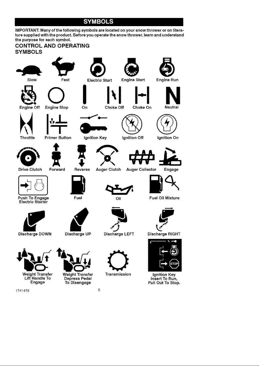
IMPORTANT: Many of the following symbols are located on your snow thrower or on litera-
ture supplied with the product. Before you operate the snow thrower, learn and understand
the purpose for each symbol.
CONTROL AND OPERATING
SYMBOLS
Slow Fast Electric Start Engine Start Engine Run
@0 I I-I N
Engine Off Engine Stop On Choke Off Choke On Neutral
®®
Throttle Primer Button Ignition Key
Drive Clutch Forward Reverse Auger Clutch Auger Collector Engage
Push To Engage Fuel Oil Fuel Oil Mixture
Electric Starter
Ignition Off Ignition On
VVV
w d - #
Discharge DOWN Discharge UP Discharge LEFT Discharge RIGHT
Weight Transfer Weight Transfer Transmission Ignition Key
Lift Handle To Depress Pedal Insert To Run,
Engage To Disengage Pull Out To Stop.
1741478
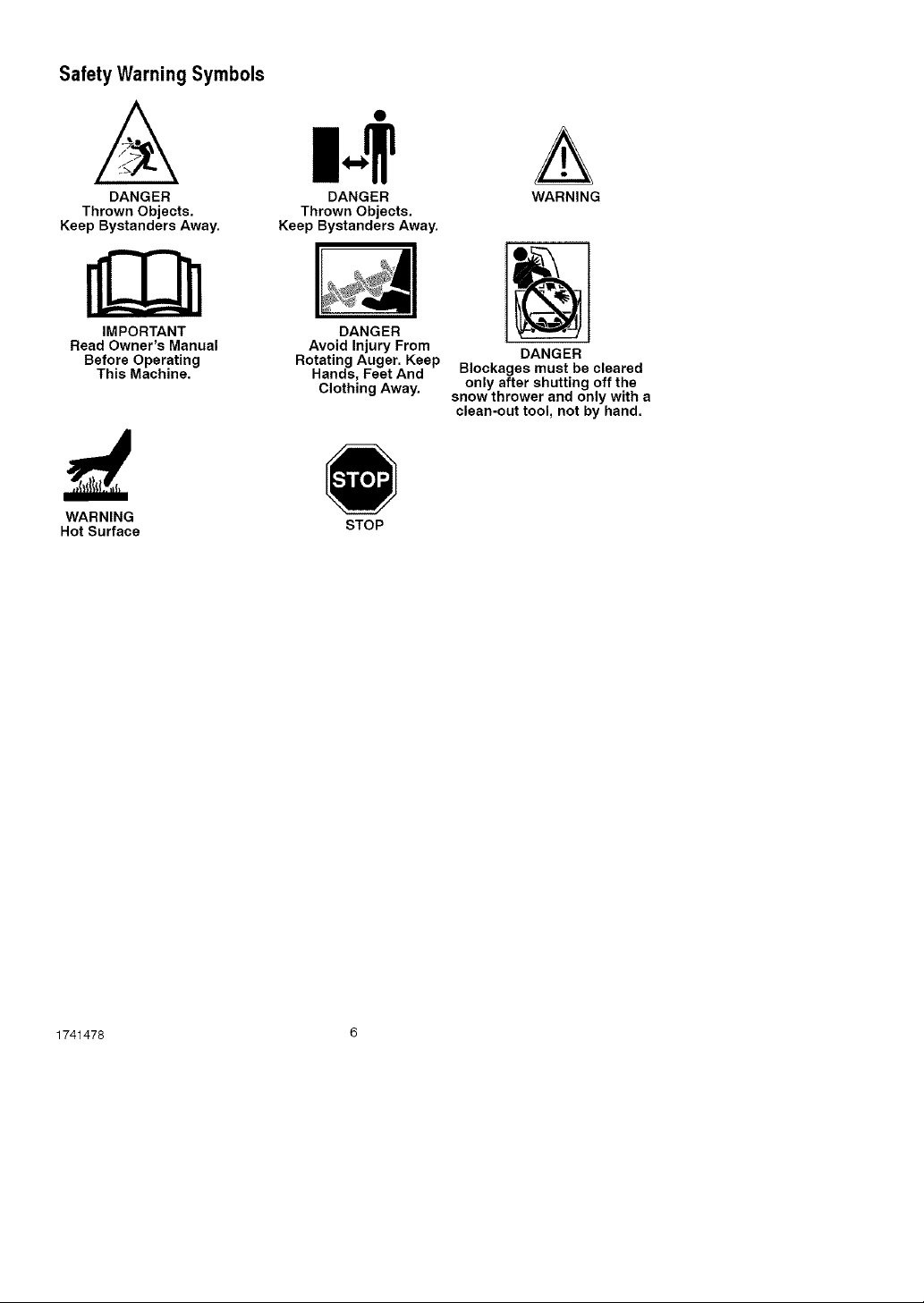
Safety Warning Symbols
A
DANGER
Thrown Objects.
Keep Bystanders Away.
IMPORTANT
Read Owner's Manual
Before Operating
This Machine.
WARNING
Hot Surface
DANGER
Thrown Objects.
Keep Bystanders Away.
DANGER
Avoid Injury From
Rotating Auger. Keep
Hands, Feet And
Clothing Away.
STOP
A
WARNING
DANGER
Blockages must be cleared
only after shutting off the
snow thrower and only with a
clean-out tool, not by hand.
1741478 6
Contents of Parts Bag
1 - Owner's Manual (not shown)
1 - Electric Starter Cord (not shown)
1 - Fuel Stabilizer (not shown)
_lb ARNING: Always wearsafety glasses or eye shields
while assembling snow
thrower.
TOOLS REQUIRED
1 - Knife to cut carton
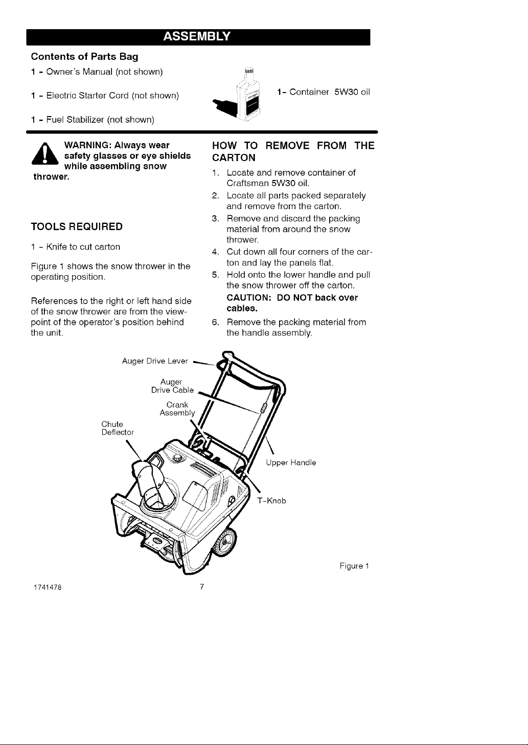
Figure 1 shows the snow thrower in the
operating position.
References to the right or left hand side
of the snow thrower are from the view-
point of the operator's position behind
the unit.
J_
1- Container 5W30 oi!
HOW TO REMOVE FROM THE
CARTON
1. Locate and remove container of
Craftsman 5W30 oil.
2. Locate all parts packed separately
and remove from the carton,
3. Remove and discard the packing
material from around the snow
thrower.
4. Cut down all four corners of the car-
ton and lay the panels flat.
5. Hold onto the lower handle and pull
the snow thrower off the carton.
CAUTION: DO NOT back over
cables,
6. Remove the packing material from
the handle assembly.
Auger Drive Lever
Auger
Drive Cable
Crank
Assembly
Chute
Deflector
1741478 7
Upper Handle
T-Knob
Figure 1
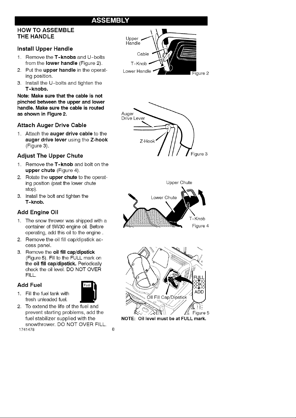
HOW TO ASSEMBLE
THE HANDLE
Install Upper Handle
1. Remove the T-knobs and U-bolts
from the lower handle (Figure 2).
2. Put the upper handle in the operat-
ing position.
3. Install the U-bolts and tighten the
T-knobs.
Note: Make sure that the cable is not
pinched between the upper and lower
handle, Make sure the cable is routed
as shown in Figure 2.
Attach Auger Drive Cable
1. Attach the auger drive cable to the
auger drive lever using the Z-hook
(Figure 3).
Adjust The Upper Chute
1. Remove the T-knob and bolt on the
upper chute (Figure 4).
2. Rotate the upper chute to the operat-
ing position (past the lower chute
stop).
3. Install the bolt and tighten the
T-knob.
Add Engine Oil
1. The snow thrower was shipped with a
container of 5W30 engine oil. Before
operating, add this oil to the engine.
2. Remove the oil fill cap/dipstick ac-
cess panel.
3. Remove the oil fill cap/dipstick
(Figure 5). Fill to the FULL mark on
the oil fill cap/dipstick. Periodically
check the oil level. DO NOT OVER
FILL.
Add Fuel
1. Fil! the fuel tank with
fresh unleaded fue!.
2. To extend the life of the fuel and
prevent starting problems, add the
fuel stabilizer supplied with the
snowthrower. DO NOT OVER FILL.
1741478
Upper
Handle
Cable
T-Knob
gure 2
Au(
Drive Lever
Figure 3
Upper Chute
Lower Chute
X
T-Knob
Figure 4
Oil Fill
NOTE: Oil level must be at FULL mark.
Figure 5
_" CHECKLIST
Before you operate your new snow
thrower, to ensure that you receive the
best performance and satisfaction from
this quality product, please review the
following checklist:
_" All assembly instructions have been
completed.
_" The discharge chute rotates freely.
_" No remaining loose parts in carton.
While learning how to use your snow
thrower, pay extra attention to the fol-
lowing important items:
_" Make sure engine oil is at proper lev-
el. Use a high quality detergent oil
classified "For Service SG, SH, SJ,
SL, or higher".
_" Make sure the fuel tank is filled prop-
erly with clean, fresh, unleaded gaso-
line with a minimum of 85 octane.
_" Become familiar with the location of
all controls and understand their
function.
_" Before starting the engine, make sure
all controls operate correctly.
1741478 9
[o)_J_P_o)_l
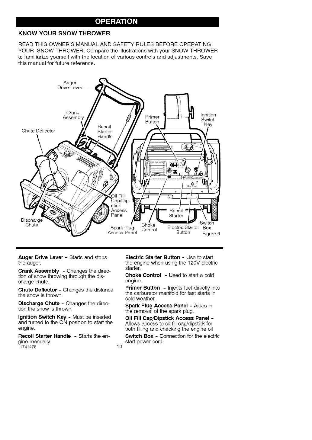
KNOW YOUR SNOW THROWER
READ THIS OWNER'S MANUAL AND SAFETY RULES BEFORE OPERATING
YOUR SNOW THROWER. Compare the illustrations with your SNOW THROWER
to familiarize yourself with the location of various controls and adjustments. Save
this manual for future reference.
Auger
Drive Lever-
Crank Ignition
Assembly Primer Switch
ChuteDeflector
Key
\
stick
Access
Panel
Discharge
Chute
Auger Drive Lever - Starts and stops
the auger.
Crank Assembly - Changes the direc-
tion of snow throwing through the dis-
charge chute,
Chute Deflector - Changes the distance
the snow is thrown.
Discharge Chute - Changes the direc-
tion the snow is thrown,
Ignition Switch Key - Must be inserted
and turned to the ON position to start the
engine.
Recoil Starter Handle - Starts the en-
gine manually.
1741478 10
Spark Ptug Control Electric Starter Box
Access Panel Button Figure 6
Choke
Electric Starter Button - Use to start
the engine when using the 120V electric
starter,
Choke Control - Used to start a cold
engine.
Primer Button - Injects fuel directly into
the carburetor manifold for fast starts in
cold weather.
Spark Plug Access Panel - Aides in
the removal of the spark plug.
Oil Fill Cap/Dipstick Access Panel -
Allows access to oil fill cap/dipstick for
both filling and checking the engine oil
Switch Box - Connection for the electric
start power cord.
[o)_J_P_o)_l
_i ARNING: Read Owner's
Manual before operating
machine. Never direct dis-
charge toward bystanders. Stop the
engine before unclogging discharge
chute or auger housing and before
leaving the machine.
TO STOP YOUR
SNOW THROWER
1. To stop throwing snow, release the
auger drive lever. See Figure 6.
NOTE: If the snow thrower contin-
ues to slowly move forward, see
"How To Adjust The Auger Control
Cable" in the Service And Adjust-
ment Section.
2. To stop the engine, move the igni-
tion switch key to the off position.
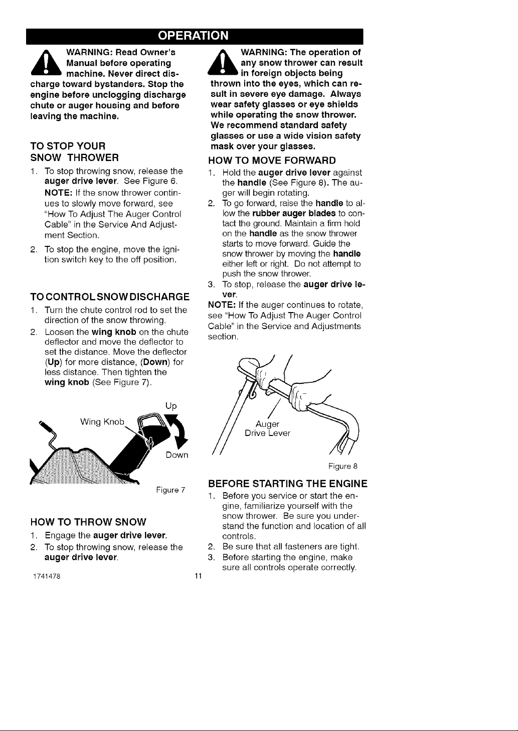
TO CONTROL SNOW DISCHARGE
1. Turn the chute control rod to set the
direction of the snow throwing.
2. Loosen the wing knob on the chute
deflector and move the deflector to
set the distance. Move the deflector
(Up) for more distance, (Down) for
less distance. Then tighten the
wing knob (See Figure 7).
_i ARNING: The operation of
any snow thrower can result
in foreign objects being
thrown into the eyes, which can re-
sult in severe eye damage. Always
wear safety glasses or eye shields
while operating the snow thrower.
We recommend standard safety
glasses or use a wide vision safety
mask over your glasses.
HOW TO MOVE FORWARD
1. Hold the auger drive lever against
the handle (See Figure 8). The au-
ger will begin rotating.
2. To go forward, raise the handle to al-
low the rubber auger blades to con-
tact the ground. Maintain a firm hold
on the handle as the snow thrower
starts to move forward. Guide the
snow thrower by moving the handle
either left or right. Do not attempt to
push the snow thrower.
3. To stop, release the auger drive le-
ver.
NOTE: If the auger continues to rotate,
see "How To Adjust The Auger Control
Cable" in the Service and Adjustments
section.
Up
Winc
Down
Figure 7
HOW TO THROW SNOW
1. Engage the auger drive lever.
2. To stop throwing snow, release the
auger drive lever.
1741478
Auger
Drive Lever
Figure 8
BEFORE STARTING THE ENGINE
1. Before you service or start the en-
gine, familiarize yourself with the
snow thrower. Be sure you under-
stand the function and location of all
controls.
2. Be sure that all fasteners are tight.
3. Before starting the engine, make
sure all controls operate correctly.
[o)_J_P_o)_l
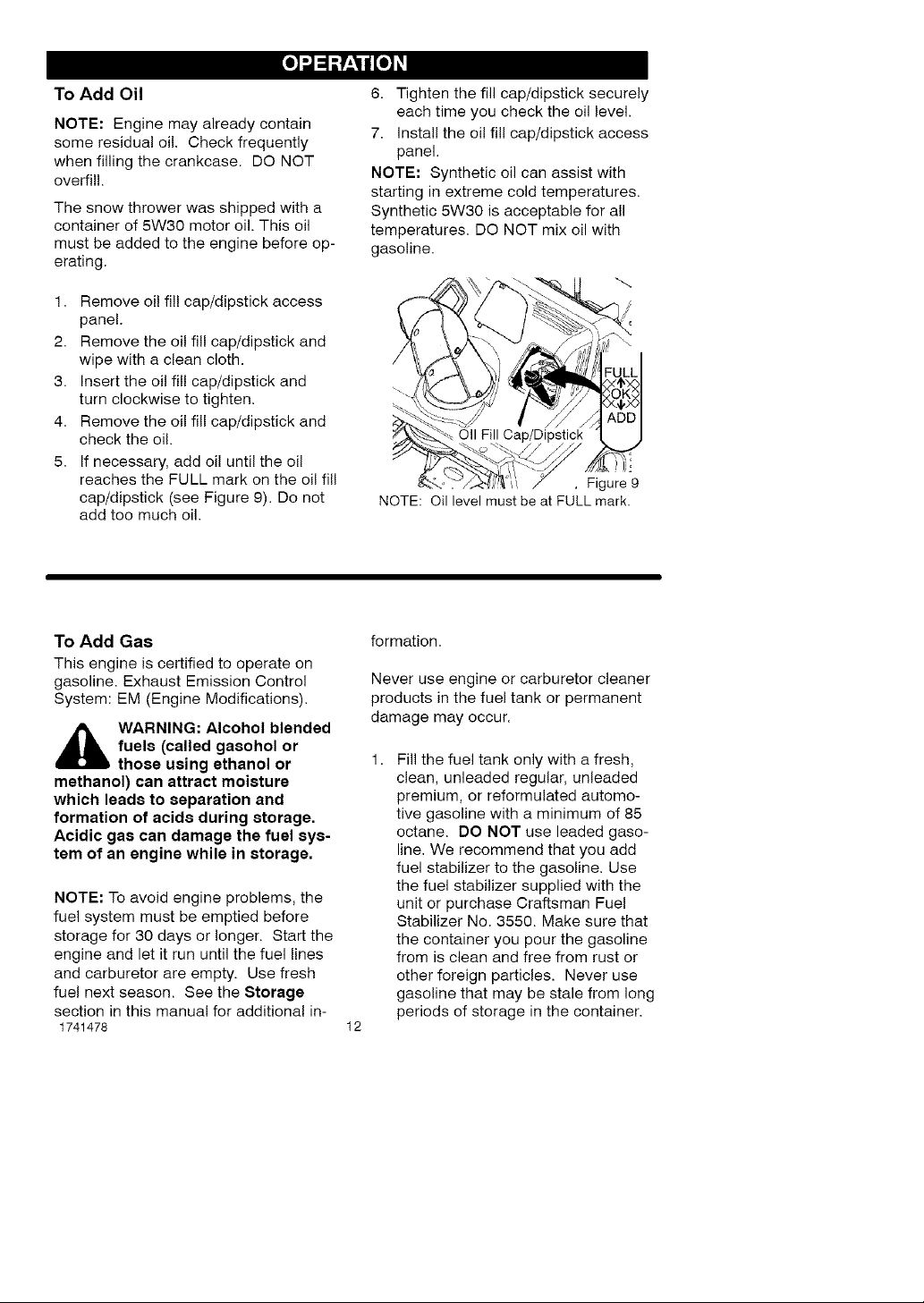
To Add Oil
NOTE: Engine may already contain
some residual oil. Check frequently
when filling the crankcase. DO NOT
overfil!.
The snow thrower was shipped with a
container of 5W30 motor oil. This oil
must be added to the engine before op-
erating.
1. Remove oi! fi!! cap/dipstick access
panel.
2. Remove the oil fill cap/dipstick and
wipe with a clean cloth.
3. Insert the oil fill cap/dipstick and
turn clockwise to tighten.
4. Remove the oil fill cap/dipstick and
check the oil.
5. If necessary, add oil until the oil
reaches the FULL mark on the oil fill
cap/dipstick (see Figure 9). Do not
add too much oil.
6. Tighten the fill cap/dipstick securely
each time you check the oil level.
7. Install the oil fill cap/dipstick access
panel.
NOTE: Synthetic oil can assist with
starting in extreme cold temperatures.
Synthetic 5W30 is acceptable for all
temperatures. DO NOT mix oil with
gasoline.
Oil Fill
!i.'
, Figure 9
NOTE: Oil level must be at FULL mark.
To Add Gas
This engine is certified to operate on
gasoline. Exhaust Emission Control
System: EM (Engine Modifications).
A ARNING: Alcohol blended
fuels (called gaeohol or
those using ethanol or
methanol) can attract moisture
which leads to separation and
formation of acids during storage.
Acidic gas can damage the fuel sys-
tem of an engine while in storage.
NOTE: To avoid engine problems, the
fuel system must be emptied before
storage for 30 days or longer. Start the
engine and let it run until the fuel lines
and carburetor are empty. Use fresh
fuel next season. See the Storage
section in this manual for additional in-
1741478
formation.
Never use engine or carburetor cleaner
products in the fuel tank or permanent
damage may occur.
Fill the fuel tank only with a fresh,
clean, unleaded regular, unleaded
premium, or reformulated automo-
tive gasoline with a minimum of 85
octane. DO NOT use leaded gaso-
line. We recommend that you add
fuel stabilizer to the gasoline. Use
the fuel stabilizer supplied with the
unit or purchase Craftsman Fuel
Stabilizer No. 3550. Make sure that
the container you pour the gasoline
from is clean and free from rust or
other foreign particles. Never use
gasoline that may be stale from long
periods of storage in the container.
12
[o)_J_P_o)_l
,_ WARNING: Gasoline is flam-
gasoline.
• Turn engine off and let engine
• Do not fill fuel tank while snow
• Keep away from open flame or an
mable. Always use caution
when handling or storing
cool at least two minutes before
removing the gas cap.
thrower is running, when it is hot,
or when snow thrower is in an en-
closed area.
electrical spark and do not smoke
while filling the fuel tank.
• Never fill the tank completely. Fill
the tank to approximately 1-1/2"
below the top of the tank opening
to provide space for expansion of
fuel.
• Always fill fuel tank outdoors and
use a funnel or spout to prevent
spilling.
• Make sure to wipe up any spilled
fuel before stating the engine.
• Store gasoline in a clean, ap-
proved container and keep the
cap in place on the container.
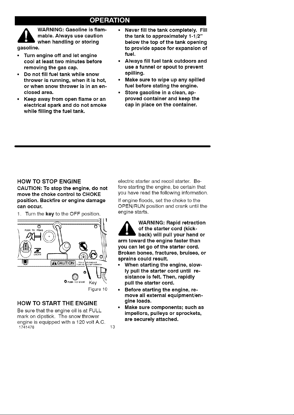
HOW TO STOP ENGINE
CAUTION: To stop the engine, do not
move the choke control to CHOKE
position. Backfire or engine damage
can occur.
1. Turn the key to the OFF position.
' f
_.T Key
Figure 10
HOW TO START THE ENGINE
Be sure that the engine oil is at FULL
mark on dipstick. The snow thrower
engine is equipped with a 120 volt A.C.
1741478 13
electric starter and recoil starter. Be-
fore starting the engine, be certain that
you have read the following information.
If engine floods, set the choke to the
OPEN/RUN position and crank until the
engine starts.
,_ WARNING: Rapid retraction
of the starter cord (kick-
back) will pull your hand or
arm toward the engine faster than
you can let go of the starter cord.
Broken bones, fractures, bruises, or
sprains could result.
• When starting the engine, slow-
ly pull the starter cord until re-
sistance is felt. Then, rapidly
pull the starter cord.
• Before starting the engine, re-
move all external equipment/en-
gine loads.
• Make sure components; such as
impellors, pulleys or sprockets,
are securely attached.
[o)_J_P_o)_l
_lb ARNING: The starter i8
designed to operate on 120 volt AC
household current. It must be prop-
erly grounded at all times to avoid
the possibility of electrical shock
which may be injurious to operator.
• Follow all instructions carefully
• Determine that your house wiring
How To Start A Cold Engine
1. Make sure auger drive lever is in
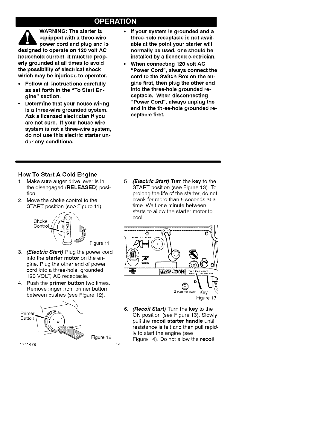
2. Move the choke control to the
3. (Electric Start) Plug the power cord
4. Push the primer button two times.
equipped with a three-wire
power cord and plug and i8
as set forth in the "To Start En-
gine" section.
i8 a three-wire grounded system.
Ask a licensed electrician if you
are not sure. If your house wire
system is not a three-wire system,
do not use this electric starter un-
der any conditions.
the disengaged (RELEASED) posi-
tion.
START position (see Figure 11).
Control
Choke
Figure 11
into the starter motor on the en-
gine. Plug the other end of power
cord into a three-hole, grounded
120 VOLT, AC receptacle.
Remove finger from primer button
between pushes (see Figure 12).
If your system is grounded and a
three-hole receptacle is not avail-
able at the point your starter will
normally be used, one should be
installed by a licensed electrician.
When connecting 120 volt AC
"Power Cord", always connect the
cord to the Switch Box on the en-
gine first, then plug the other end
into the three-hole grounded re-
ceptacle. When disconnecting
"Power Cord", always unplug the
end in the three-hole grounded re-
ceptacle first.
(Electric Start) Turn the key to the
START position (see Figure 13). To
prolong the life of the starter, do not
crank for more than 5 seconds at a
time. Wait one minute between
starts to allow the starter motor to
cool.
OPu_o_,._ Key !
Figure t3
Primer
Button"
1741478
Figure 12
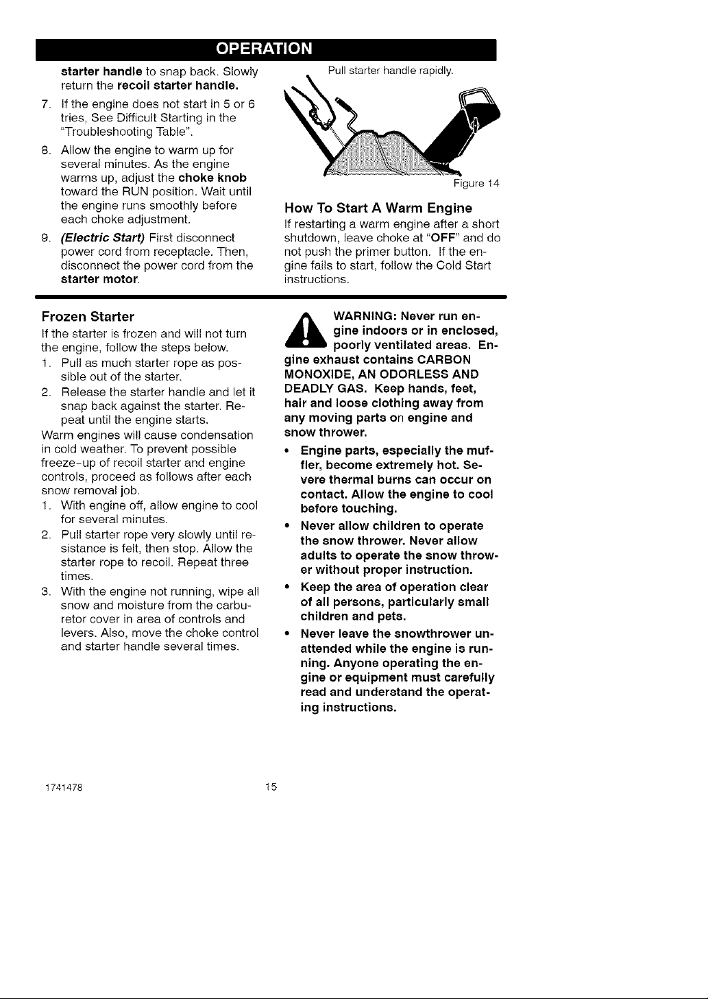
(Recoil Start) Turn the key to the
ON position (see Figure 13). Slowly
pull the recoil starter handle until
resistance is felt and then pull tepid-
ly to start the engine (see
Figure 14). Do not allow the recoil
14
[o)_J_P_o)_l
starter handle to snap back. Slowly
return the recoil starter handle.
7. If the engine does not start in 5 or 6
tries, See Difficult Starting in the
"Troubleshooting Table".
8. Allow the engine to warm up for
several minutes. As the engine
warms up, adjust the choke knob
toward the RUN position. Wait until
the engine runs smoothly before
each choke adjustment.
9. (Electric Start) First disconnect
power cord from receptacle. Then,
disconnect the power cord from the
starter motor.
Frozen Starter
If the starter is frozen and will not turn
the engine, follow the steps below.
1. Pull as much starter rope as pos-
sible out of the starter.
2. Release the starter handle and let it
snap back against the starter. Re-
peat until the engine starts.
Warm engines will cause condensation
in cold weather. To prevent possible
freeze-up of recoil starter and engine
controls, proceed as follows after each
snow removal job.
1. With engine off, allow engine to cool
for several minutes.
2. Pull starter rope very slowly until re-
sistance is felt, then stop. Allow the
starter rope to recoil. Repeat three
times.
3. With the engine not running, wipe all
snow and moisture from the carbu-
retor cover in area of controls and
levers. Also, move the choke control
and starter handle several times.
Pull starter handle rapidly.
Figure 14
How To Start A Warm Engine
if restarting a warm engine after a short
shutdown, leave choke at "OFF" and do
not push the primer button. Ifthe en-
gine fails to start, fol!ow the Cold Start
instructions.
,_ WARNING: Never run en-
gine indoors or in enclosed,
poorly ventilated areas. En-
gine exhaust contains CARBON
MONOXIDE, AN ODORLESS AND
DEADLY GAS. Keep hands, feet,
hair and loose clothing away from
any moving parts on engine and
snow thrower.
• Engine parts, especially the muf-
fler, become extremely hot. Se-
vere thermal burns can occur on
contact. Allow the engine to cool
before touching.
• Never allow children to operate
the snow thrower. Never allow
adults to operate the snow throw-
er without proper instruction.
• Keep the area of operation clear
of all persons, particularly small
children and pets.
• Never leave the snowthrower un-
attended while the engine is run-
ning. Anyone operating the en-
gine or equipment must carefully
read and understand the operat-
ing instructions.
1741478 15
[o)_J_P_o)_l
HOW TO CLEAR
A CLOGGED DISCHARGE CHUTE
with the rotating impeller in-
WARNING: Hand contact
the most common cause of injury as-
sociated with snow throwers. Never
use your hand to clean out the dis-
charge chute.
To Clear The Chute:
• SHUT OFF THE ENGINE!
• Wait 10 seconds to be sure that the
• Always use a clean-out tool, not
side the discharge chute is
impeller blades have stopped ro-
tating.
your hands.
Use a clean-out tool to remove snow
from the auger housing.
• Release the auger drive lever.
• Pull out the key.
• Disconnect spark plug wire.
• Do not place your hands in the au-
ger or discharge chute. Use a
clean-out tool to remove snow or
debris.
_lb ARNING: Blockage must
be cleared only after shut-
ting off the snow thrower
and only with a clean-out tool, not
by hand.
SNOW THROWING TIPS
1. When the handle is raised, the au-
ger blades will engage the ground
and the snow thrower will move for-
ward. When the auger drive lever is
released, the auger blades will stop.
if the blades do not stop, see "How
To Adjust The Auger Drive Cable" in
the Service And Adjustment section.
2. Most efficient snow throwing is ac-
complished when the snow is re-
moved immediately after if fails.
3. Let the engine (motor) and the snow
thrower adjust to outdoor tempera-
ture before starting to clear snow.
4. For complete snow removal, slightly
overlap each previous path.
5. Whenever possible, discharge the
snow down wind.
6. The distance the snow will be dis-
charged can be adjusted by moving
the discharge chute deflector. Raise
the deflector for more distance or
lower the deflector for less distance.
7. In windy conditions, lower the chute
deflector to direct the discharged
snow close to the ground where it is
1741478 16
less likely to blow into unwanted
areas.
8. For safety and to prevent damage
to the snow thrower, keep the area
to be cleared free of stones, toys
and other foreign objects.
9. When clearing snow from crushed
rock or gravel driveways, do not al-
low the auger blades to contact the
driveway. Move the handle down to
slightly raise the auger blades.
10. The forward speed of the snow
thrower is dependent on the depth
and weight of the snow. Experience
will establish the most effective
method of using the snow thrower
under different conditions.
11. After each snow throwing job, allow
the engine to run for a few minutes.
The snow and accumulated ice wil!
melt off the engine.
12. Clean the snow thrower after each
use.
13. Remove ice, snow and debris from
the entire snow thrower. Flush with
water to remove all salt or other
chemicals. Wipe snow thrower dry.

[o)_J_P_o)_l
DRY AND AVERAGE SNOW
1. Snow up to eight inches deep can
be removed rapidly and easily by
walking at a moderate rate. For
snow or drifts of a greater depth,
slow your pace to allow the dis-
charge chute to dispose of the snow
as rapidly as the auger receives the
snow.
2. Plan to have the snow discharged in
the direction the wind is blowing.
WET PACKED SNOW
Move slowly into wet, packed snow. If
the wet, packed snow causes the auger
to slow down or the discharge chute be-
gins to clog, back off and begin a series
of short back and forth jabs into the
snow. These short back and forth jabs,
four to six inches, will "belch" the snow
from the chute.
SNOW BANKS AND DRIFTS
In snow of greater depth than the unit,
use the same "jabbing" technique de-
scribed above. Turn the discharge
chute away from the snow bank. More
time will be required to remove snow of
this type than level snow.
1741478 17
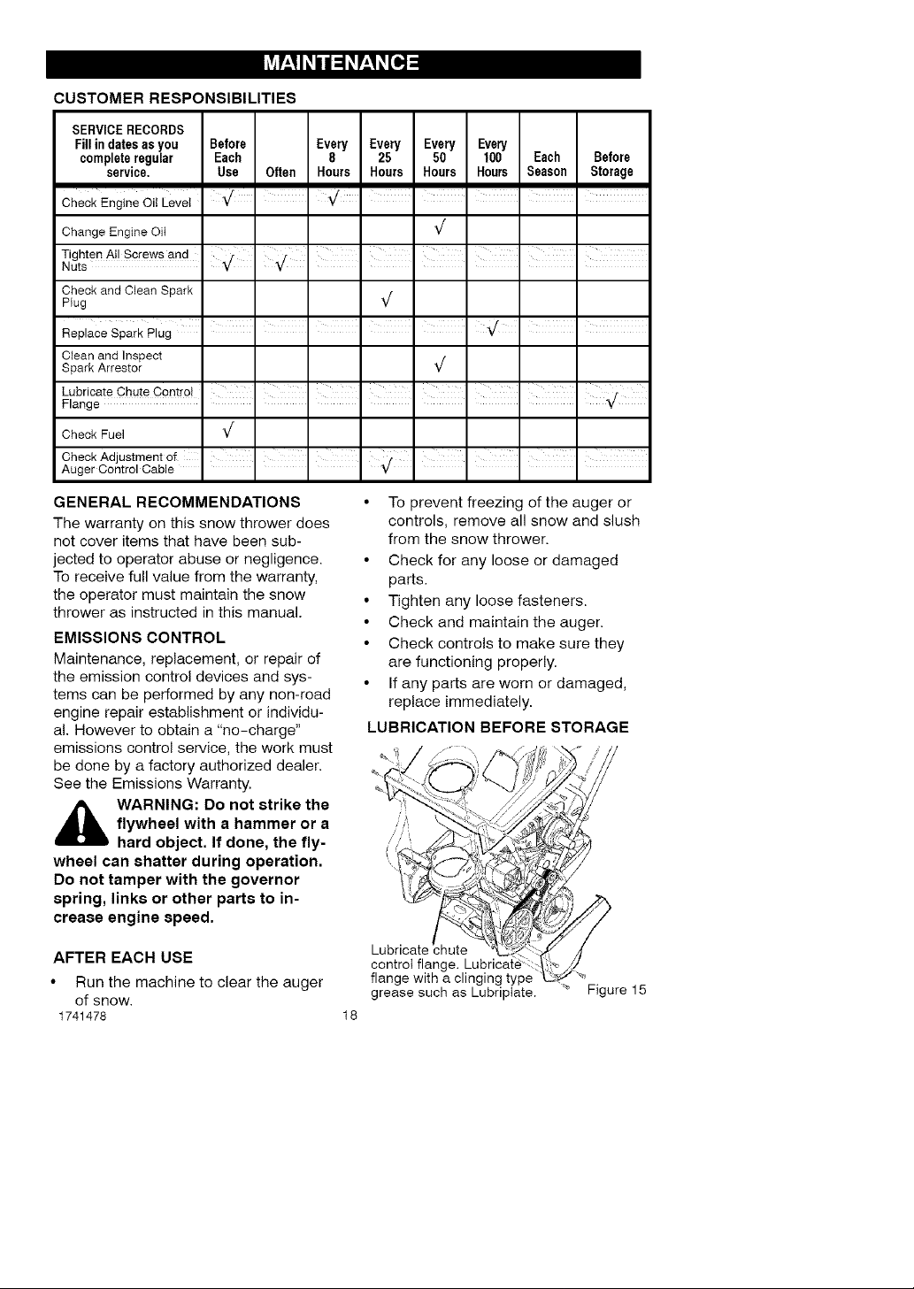
CUSTOMER RESPONSIBILITIES
SERVICERECORDS
Fill in dates asyou Before Every Every Every Every
completeregular Each 8 25 50 100 Each Before
service, Use Often Hours Hours Hours Hours Season Storage
Check Engine Oil Leve_ • ' " I I I I
Change Engine OiI _/
Tighten All Screws and
Nuts
Checkand Clean Spark
Plug _/
Clean and Inspect
Spark Arrestor _/
Check Fuel _/
CheckAdjustmentof I I I } I I I I
Auger Centre Cab e Y
GENERAL RECOMMENDATIONS
The warranty on this snow thrower does
not cover items that have been sub-
jected to operator abuse or negligence.
To receive full value from the warranty,
the operator must maintain the snow
thrower as instructed in this manual.
EMISSIONS CONTROL
Maintenance, replacement, or repair of
the emission control devices and sys-
tems can be performed by any non-road
engine repair establishment or individu-
al. However to obtain a "no-charge"
emissions control service, the work must
be done by a factory authorized dealer.
See the Emissions Warranty.
_ WARNING: Do not strike the
flywheel with a hammer or a
hard object. If done, the fly-
wheel can shatter during operation.
Do not tamper with the governor
spring, links or other parts to in-
crease engine speed.
AFTER EACH USE
• Run the machine to clear the auger
of snow.
1741478
• To prevent freezing of the auger or
controls, remove all snow and slush
from the snow thrower.
• Check for any loose or damaged
parts.
• Tighten any loose fasteners.
• Check and maintain the auger.
• Check controls to make sure they
are functioning properly.
• If any parts are worn or damaged,
replace immediately.
LUBRICATION BEFORE STORAGE
control flang,
flange with a clinging type "_
grease such as Lubriptate. _ Figure 15
18
ENGINE SPECIFICATIONS
GROSS TORQUE 5.25 ft-lbs
DISPLACEMENT 148 cc
BORE 65mm (2.562 in.)
STROKE 45mm (1.750 in.)
GASOLINE 2 quarts (85 octane
CAPACITY leaded)
OIL CAPACITY 5W30
(16 oz capacity)
SPARK PLUG: Champion RJ19LM
(Gap .030 in.) or
equivalent
VALVE Intake: 0.005-0.007 in.
CLEARANCE: Exhaust: 0.007-0.009 in.
ARMATURE
AIR GAP: 0.006-0.010 in.
POWER RATINGS
The gross power rating for individual
gas engine models is labeled in
accordance with SAE (Society of
Automotive Engineers) code J1940
(Small Engine Power & Torque Rating
Procedure), and rating performance
has been obtained and corrected in
accordance with SAE J1995 (Revision
2002-05). Torque values are derived at
3060 RPM; horsepower values are
derived at 3600 RPM. Actual gross
engine power will be lower and is
affected by, among other things,
ambient operating conditions and
engine-to-engine variability. Given both
the wide array of products on which
engines are placed and the variety of
environmental issues applicable to
operating the equipment, the gas
engine will not develop the rated gross
power when used in a given piece of
power equipment (actual "on-site" or
net power). This difference is due to a
variety of factors including, but not
limited to, accessories (air cleaner,
exhaust, charging, cooling, carburetor,
fuel pump, etc.), application limitations,
ambient operating conditions (tempera-
ture, humidity, altitude), and engine-to-
engine variability. Due to manufacturing
and capacity limitations, Briggs &
Stratton may substitute an engine of
higher rated power for this Series
engine.
SNOW THROWER
ENGINE
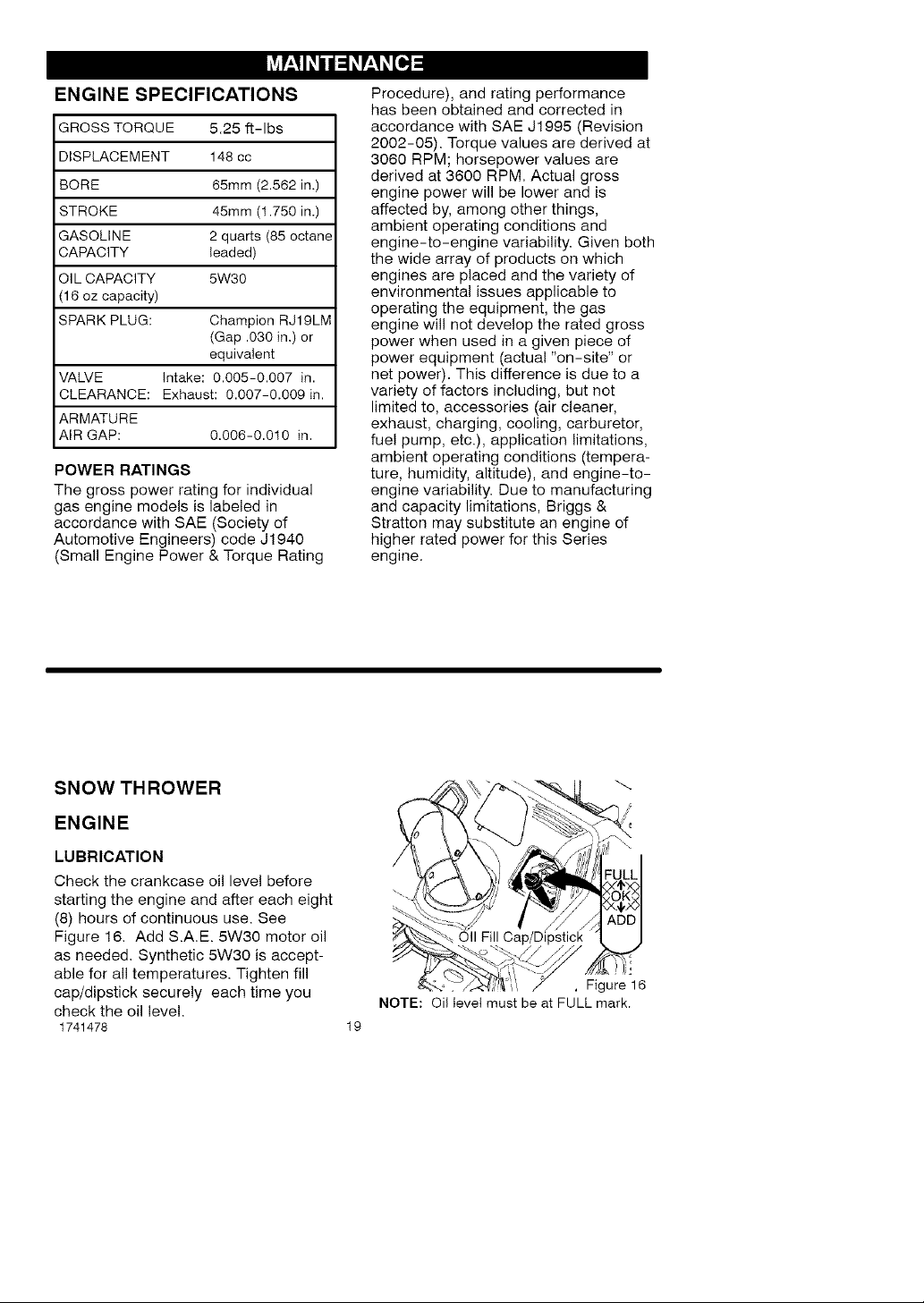
LUBRICATION
Check the crankcase oil level before
starting the engine and after each eight
(8) hours of continuous use. See
Figure 16. Add S.A.E. 5W30 motor oil
as needed. Synthetic 5W30 is accept-
able for all temperatures. Tighten fill
cap/dipstick securely each time you
check the oil level.
1741478 19
Oil Fill
!i.'
, Figure 16
NOTE: Oi! level must be at FULL mark.
Change the oi! every fifty (50) hours or
at least once a year if the snow thrower
is not used for fifty (50) hours.
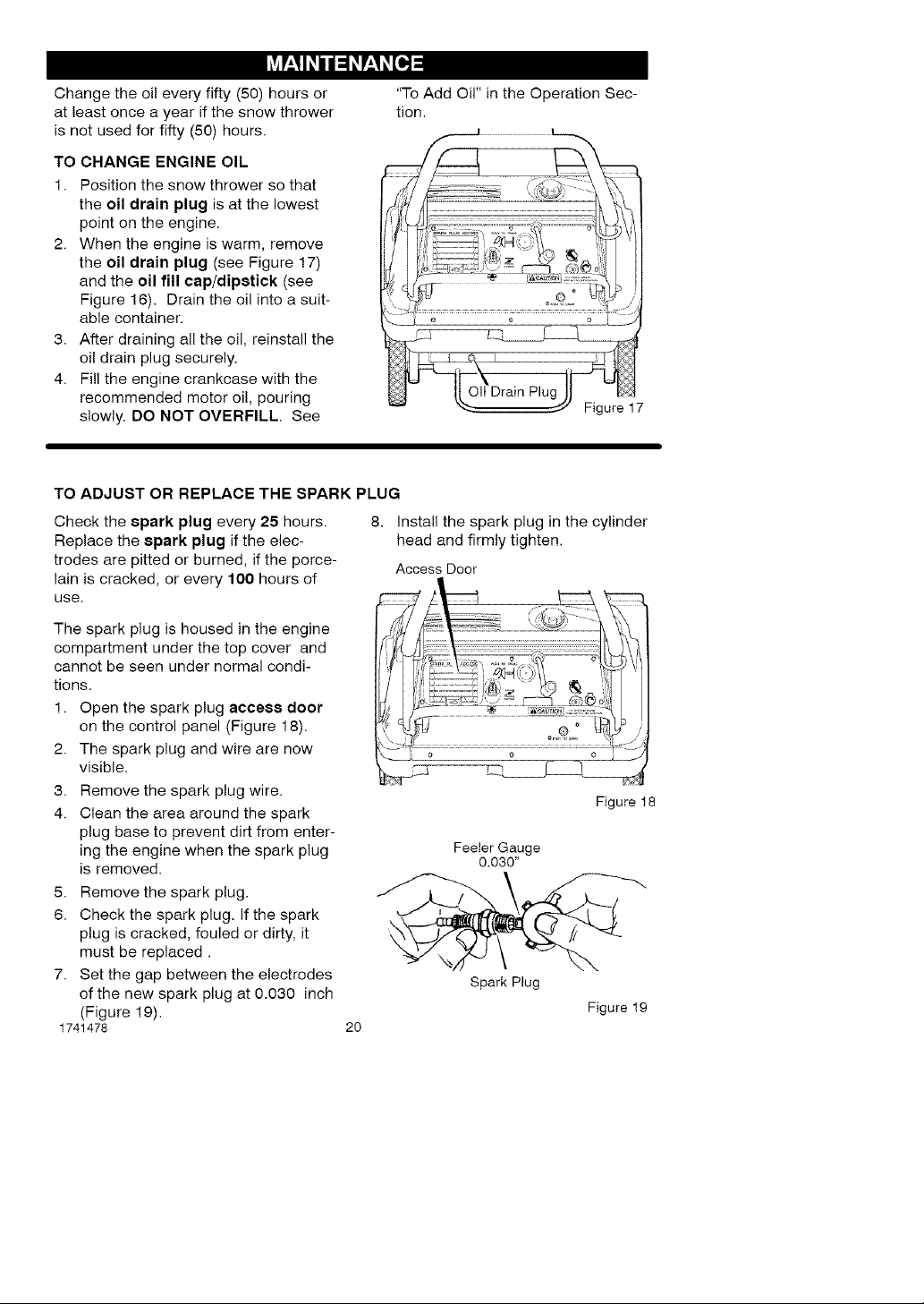
TO CHANGE ENGINE OIL
1. Position the snow thrower so that
the oil drain plug is at the lowest
point on the engine.
2. When the engine is warm, remove
the oil drain plug (see Figure 17)
and the oil fill cap/dipstick (see
Figure 16). Drain the oil into a suit-
able container.
3. After draining all the oil, reinstall the
oil drain plug securely.
4. Fill the engine crankcase with the
recommended motor oil, pouring
slowly. DO NOT OVERFILL. See
TO ADJUST OR REPLACE THE SPARK PLUG
Check the spark plug every 25 hours.
8. install the spark plug in the cylinder
Replace the 8park plug if the elec-
trodes are pitted or burned, if the porce-
lain is cracked, or every 100 hours of
use.
"To Add Oil" in the Operation Sec-
tion.
head and firmly tighten.
Access Door
The spark plug is housed in the engine
compartment under the top cover and
cannot be seen under normal condi-
tions.
1. Open the spark plug acce88 door
on the control panel (Figure 18).
2. The spark plug and wire are now
visible.
3. Remove the spark plug wire.
4. Clean the area around the spark
plug base to prevent dirt from enter-
ing the engine when the spark plug
is removed.
5. Remove the spark plug.
6. Check the spark plug. If the spark
plug is cracked, fouled or dirty, it
must be replaced.
7. Set the gap between the electrodes
of the new spark plug at 0.030 inch
(Figure 19).
1741478
2O
Feeler Gauge
0.030"
Spark Plug
Figure 18
Figure 19
_ ARNING: To prevent acci-
dental starting when making
any adjustments or repairs,
always disconnect the spark plug
wire and place it where it cannot
make contact with the spark plug.
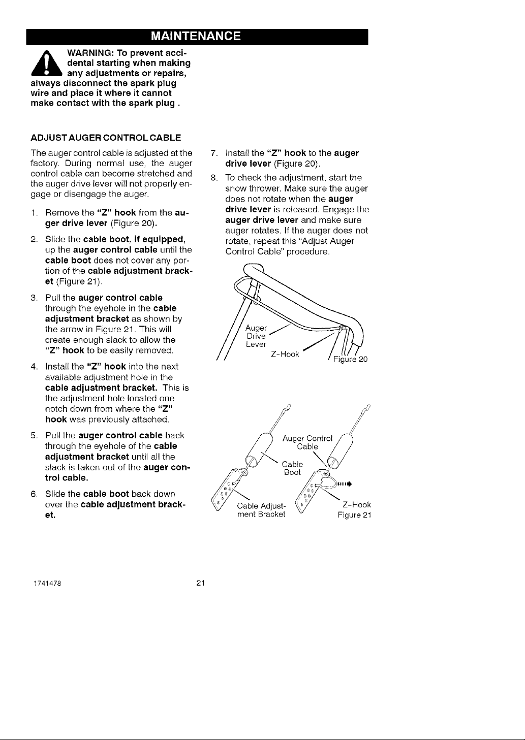
ADJUST AUGER CONTROL CABLE
The auger control cable is adjusted at the 7.
factory. During normal use, the auger
control cable can become stretched and 8.
the auger drive lever wil! not properly en-
gage or disengage the auger.
1. Remove the "Z" hook from the au-
ger drive lever (Figure 20).
2. Slide the cable boot, if equipped,
up the auger control cable until the
cable boot does not cover any por-
tion of the cable adjustment brack-
et (Figure 21).
3. Pull the auger control cable
through the eyehole in the cable
adjustment bracket as shown by
the arrow in Figure 21. This will
create enough slack to allow the
"Z" hook to be easily removed.
4. install the "Z" hook into the next
available adjustment hole in the
cable adjustment bracket. This is
the adjustment hole located one
notch down from where the "Z"
hook was previously attached.
5. Pull the auger control cable back
through the eyehole of the cable
adjustment bracket until all the
slack is taken out of the auger con-
trol cable.
6. Slide the cable boot back down
over the cable adjustment brack-
et,
install the "Z" hook to the auger
drive lever (Figure 20).
To check the adjustment, start the
snow thrower. Make sure the auger
does not rotate when the auger
drive lever is released. Engage the
auger drive lever and make sure
auger rotates, if the auger does not
rotate, repeat this "Adjust Auger
Control Cable" procedure.
Auger
Drive
Lever
Z-Hook
Cable Adjust-
ment Bracket
Auger Control
Cable
Cable
Boot
Figure 20
Z-Hook
Figure 21
1741478 21
[.,,."_o,,_ V_IZIB]P'_"_
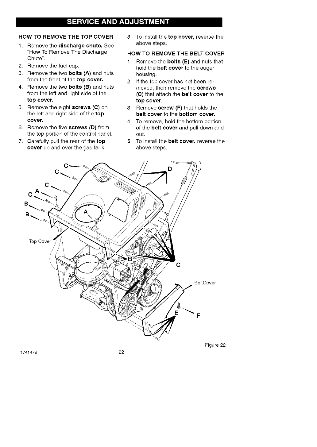
HOW TO REMOVE THE TOP COVER
1. Remove the discharge chute. See
"How To Remove The Discharge
Chute".
2. Remove the fuel cap.
3. Remove the two bolts (A) and nuts
from the front of the top cover.
4. Remove the two bolts (B) and nuts
from the left and right side of the
top cover.
5. Remove the eight screws (C) on
the left and right side of the top
cover,
6. Remove the five screws (D) from
the top portion of the control panel.
7. Carefully pull the rear of the top
cover up and over the gas tank.
8. To install the top cover, reverse the
above steps.
HOW TO REMOVE THE BELT COVER
1. Remove the bolts (E) and nuts that
hold the belt cover to the auger
housing.
2. If the top cover has not been re-
moved, then remove the screws
(C) that attach the belt cover to the
top cover.
3. Remove screw (F) that holds the
belt cover to the bottom cover.
4. To remove, hold the bottom portion
of the belt cover and pull down and
out.
5. To install the belt cover, reverse the
above steps.
Top
/
/
\
\
\
1741478 22
C
BeltCover
F
Figure 22
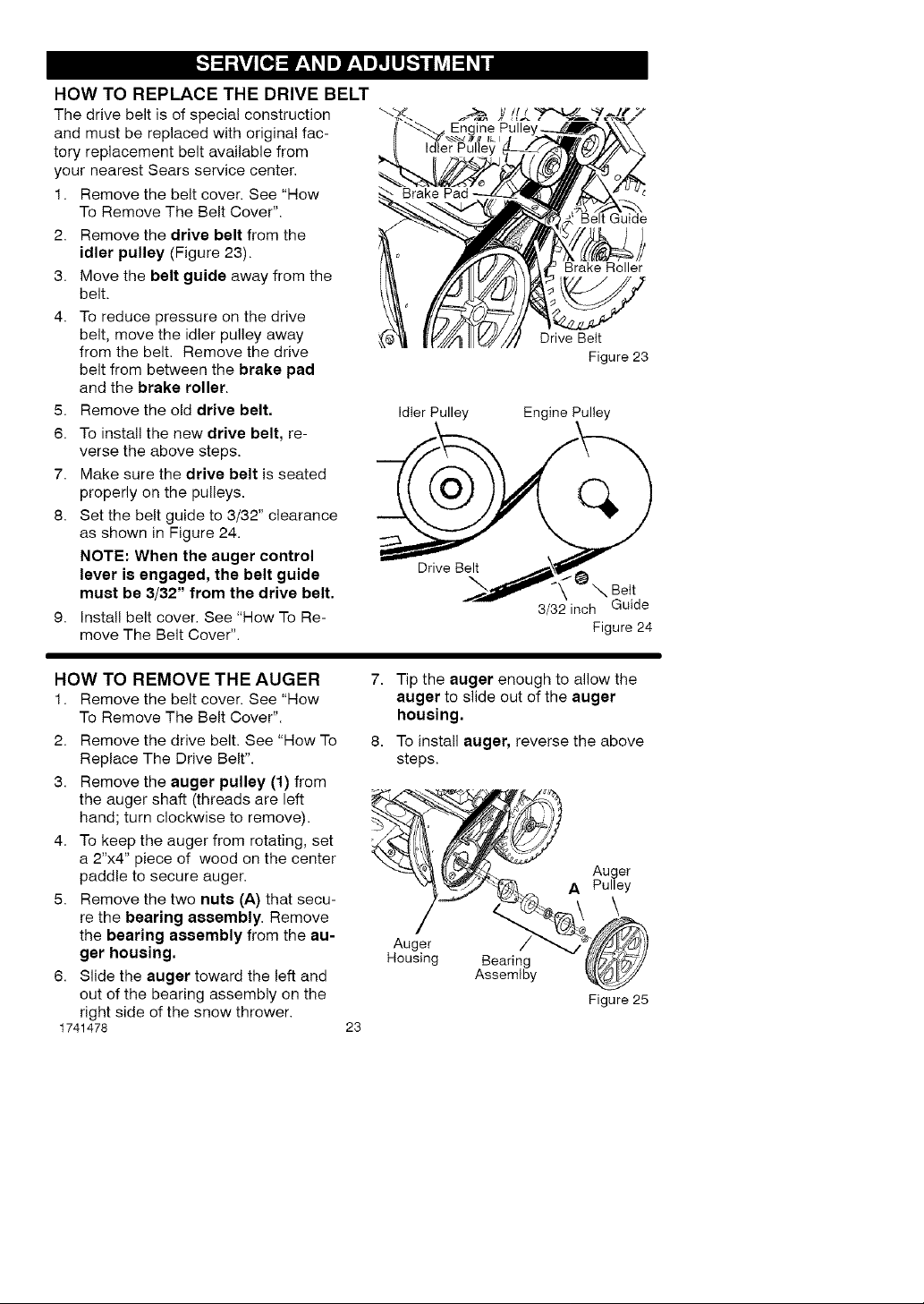
HOWTO REPLACE THE DRIVE BELT
The drive belt is of special construction
and must be replaced with original fac-
tory replacement belt available from
your nearest Sears service center.
1. Remove the belt cover. See "How
To Remove The Belt Cover".
2. Remove the drive belt from the
idler pulley (Figure 23).
3. Move the belt guide away from the
belt.
4. To reduce pressure on the drive
belt, move the idler pulley away
from the belt. Remove the drive
belt from between the brake pad
and the brake roller.
5. Remove the old drive belt.
6. To install the new drive belt, re-
verse the above steps.
7. Make sure the drive belt is seated
properly on the pulleys.
8. Set the belt guide to 3/32" clearance
as shown in Figure 24.
NOTE: When the auger control
lever is engaged, the belt guide
must be 3/32" from the drive belt.
9. Install belt cover. See "How To Re-
move The Belt Cover".
Belt Guide
Brake Roller
Drive Belt
Figure 23
Idler Pulley Engine Pulley
3/32 inch Guide
Figure 24
HOW TO REMOVE THE AUGER
1. Remove the belt cover. See "How
To Remove The Belt Cover".
2. Remove the drive belt. See "How To
Replace The Drive Belt".
3. Remove the auger pulley (1) from
the auger shaft (threads are left
hand; turn clockwise to remove).
4. To keep the auger from rotating, set
a 2"x4" piece of wood on the center
paddle to secure auger.
5. Remove the two nuts (A) that secu-
re the bearing assembly. Remove
the bearing assembly from the au-
ger housing,
6. Slide the auger toward the left and
out of the bearing assembly on the
right side of the snow thrower.
1741478
7. Tip the auger enough to allow the
auger to slide out of the auger
housing.
8. To install auger, reverse the above
steps.
-_..,__,_,_]{(t.,_<_. Auger
A Pulley
mousing Bearing _,_)_y
Assemlby _,_
Figure 25
23
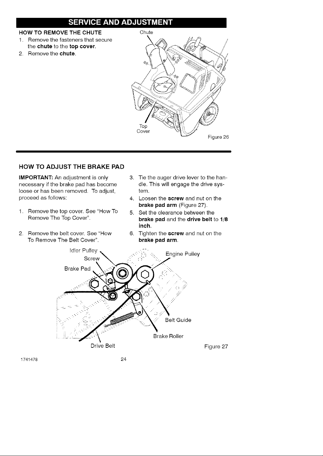
HOW TO REMOVE THE CHUTE
1. Remove the fasteners that secure
the chute to the top cover•
2. Remove the chute.
HOW TO ADJUST THE BRAKE PAD
Chute
Top
Cover
\
Figure 26
IMPORTANT: An adjustment is only
necessary if the brake pad has become
loose or has been removed• To adjust,
proceed as follows:
1. Remove the top cover• See "How To
Remove The Top Cover".
2. Remove the belt cover• See "How
To Remove The Belt Cover".
Brake Pad
Drive Belt
1741478 24
3. Tie the auger drive lever to the han-
dle• This will engage the drive sys-
tem.
4. Loosen the screw and nut on the
brake pad arm (Figure 27).
5. Set the clearance between the
brake pad and the drive belt to 1/8
inch.
6. Tighten the screw and nut on the
brake pad arm.
•:::" Belt Guide
Brake Roller
Figure 27
 Loading...