

Craftsman 536881110 Owner’s Manual
CRAFTSMAN®I
1.0 Horsepower
30 Inch Dual Stage
120V. Electric Start
SNOW THROWER
MODEL NO.
536.881110
Caution:
Read and follow all Safety Rules
and Operating Instructions before
first use of this product.
SEARS, ROEBUCK AND CO., Hoffman Estates, IL 60179 U.S.A.
F--001142J
WARRANTY STATEMENT ......
SAFETY RULES ...............
INTERNATIONAL SYMBOLS ....
ASSEMBLY ...................
OPERATION ..................
MAINTENANCE ...............
SERVICE AND ADJUSTMENT...
LIMITED TWO-YEAR WARRANTY ON CRAFTSMAN SNOW THROWER
For twoyears from the date of purchase, when this Craftsman Snow thrower ismaintained,
lubricated, and tuned up according to the operating and maintenance instructions in the
owner's manual, Sears will repair, free of charge, any defect in material or workmanship.
If this Craftsman Snow thrower is used for commercial or rental purposes, this warranty ap-
plies for only 90 days from the date of purchase.
This warranty does not cover the following:
• Items which become worn during normal use, such as spark plugs, drive belts and shear
pins.
• Repay"necessary because of operator abuse or negligence, including bent crankshafts
and the failure to maintain the equipment according to the instructionscontained in the
owner's manual.
WARRANTY SERVICE IS AVAILABLE BY RETURNING THE CRAFTSMAN SNOW
THROWERTO THE NEAREST Sears SERVICE CENTER/DEPARTMENT IN THE
UNITED STATES. THIS WARRANTY APPLIES ONLY WHILE THIS PRODUCT IS IN USE
IN THE UNITED STATES.
This warranty gives you specific legal rights,and you may also have other rights which may
vary from state to state.
Sears, Roebuck and Co., D817WA, Hoffman Estates. IL 60179
2 STORAGE .................... 31
2 TROUBLE SHOOTING CHART .. 32
4 REPAIR PARTS ................ 33
7
13 ENGINE REPAIR PARTS ........ 50
20 SPANISH (ESPAI_IOL) .......... 60
23 PARTS ORDERING/SERVICE ., 92
,_ LOOK FOR THIS SYMBOL TO POINT OUT IMPORTANT SAFETY PRECAUTIONS.
Engine Exhaust, some of its constituents, and
certain vehicle components contain or emit
chemicals known to the State of California to
cause cancer and birth defects or other repro-
ductive harm.
Battery posts, terminals and related accessories
contain lead and lead compounds, chemicals
known to the State of California to cause cancer
and birth defeCts or other reproductive harm.
WASH HANDS AFTER HANDUNG.
F-OO1142J 2
IT MEANS-- A'I-rENTIONH! BECOME ALERT!!! YOUR SAFETY IS INVOLVED.
,_ WARNING: Always discon-
make contact with spark plug to
prevent accidental starting during:
Preparation, Maintenance, or Stor-
age of your snow thrower.
IMPORTANT: Safety standards re-
quire operator presence controls to
minimize the risk of injury. Your snow
thrower is equipped with such controls.
Do not attempt to defeat the function of
the operator presence control under any
circumstances.
nect the spark plug wire
and place it where it cannot
TRAINING
1. Read the operating and service instruction
manual carefully. Be thoroughly familiar
with the controls and the proper use of the
equipment. Know how to stop the unitand
disengage the controls quickly.
2. Never allow children to operate the equip-
ment. Never allow adults to operate the
equipment without proper instruction.
3. Keep the area of operation clear of all per-
sons, particularly small children and pets.
4. Exercise caution to avoid slipping or falling
especially when operating in reverse.
PREPARATION
1. Thoroughly inspect the area where the
equipment is to be used and remove all
doormats, sleds, boards, wires, and other
foreign objects.
2. Disengage all clutches before starting the
engine (motor).
3. Do not operate the equipment without
wearing adequate winter outer garments.
Wear footwear that will Mmprovefooting on
slippery surfaces.
4. Handle fuel with care; it is highly flam-
mable.
a. Use an approved fuel container.
b. Never remove fuel tank cap or add fuel
c. Fill fuel tank outdoors with extreme
d. Replace fuel cap securely and wipe up
e. Never store fuel or snow thrower with
f. Check fuel supply before each use, al-
5.
For all units with electric starting motors
use electric starting extension cords certi-
fied CSNUL. Use only with a receptacle
that has been installed in accordance with
local inspection authorities.
6.
Adjust the snow thrower height to clear
gravel or crushed rock surface.
7.
Never attempt to make any adjustments
while the engine (motor) is running (except
when specifically recommended by manu-
facturer).
.
Let engine (motor) and snow thrower ad-
just to outdoor temperatures before starting
to clear snow.
F-001142J
Ib , . ,
to a running engine (motor) or hot en-
gine (motor).
care. Never fill fuel tank indoors.
spilled fuel.
fuel in the tank inside of a building
where fumes may reach an open flame
or spark.
lowing space for expansion as the heat
of the engine (motor) and/or sun can
cause fuel to expand.
g.
Always wear safety glasses or eye shields
during operation or while performing an ad-
justment or repair to protect eyes from
foreign objects that may be thrown from the
snow thrower.
OPERATION
1. Do not operate this machine if you are tak-
ing drugs or other medication which can
cause drowsiness or affect your ability to
operate this machine.
2. Do not use this machine ifyou are mentally
or physically unable to operate this ma-
chine safely.
3. Do not put hands or feet near or under ro-
tating parts. Keep clear of the discharge
opening at all times.
4. Exercise extreme caution when operating
on or crossing gravel drives, walks or
roads. Stay alert for hidden hazards or
traffic.
5. After striking a foreign object, stop the en-
gine (motor), remove the wire from the
spark plug, thoroughly inspect snow
thrower for any damage, and repair the
damage before restarting and operating
the snow thrower.
6. If the unit should start to vibrate abnormal-
ly, stop the engine (motor) and check im-
mediately for the cause. Vibration is
generally a warning of trouble.
7. Stop the engine (motor) whenever you
leave the operating position, before un-
cloggingthe auger/impeller housing or dis-
charge chute and when making any
repairs, adjustments, or inspections.
8. When cleaning, repairing, or inspecting,
make certain the auger/impeller and all
moving parts have stopped and all controls
are disengaged. Disconnect the spark plug
wire and keep the wire away fromthe spark
plug to prevent accidental starting.
9. Take all possible precautions when leaving
the snow thrower unattended. Disengage
the auger/impeller, stop engine (motor),
and remove key.
10. Do not runthe engine (motor) indoors, ex-
ceptwhen starting the engine (motor) and
for transporting the snow thrower in or out
ofthe building.Open the outside doors;ex-
haust fumes are dangerous (containing
CARBON MONOXIDE, an ODORLESS
and DEADLY GAS).
11. Do not clear snow across the face of
slopes. Exercise extreme caution when
changing direction on slopes. Do not at-
tempt to clear steep slopes.
12. Never operate the snow thrower without
proper guards, plates or other safety pro-
tective devices in place.
3
13.
Never operate the snow thrower near en-
closures, automobiles, window wells,
drop-offs, and the like without proper ad-
justment of the snow discharge angle.
Keep children and pets away.
14. Do not overload the machine capacity by
attempting to clear snow at too fast a rate.
15. Never operate the machine at high trans-
port speeds on slippery surfaces. Look be-
hind and use care when backing up.
16. Never direct discharge at bystanders or
allow anyone in front of the unit.
17. Disengage power to the collector/impelLer
when snow thrower is transported or not in
use.
18.
Use only attachments and accessories ap-
proved by the manufacturer of the snow
thrower (such as tire chains, electric start
kits, ect.).
19.
Never operate the snow thrower without
good visibility or light. Always be sure of
your footing and keep a firm hold on the
handlesP Walk;never run.
20. Do not over-reach. Keep proper footing
and balance at all times.
21. Do not attempt to use snow thrower on a
reef.
MAINTENANCE AND STORAGE
1. Check shear bolts and other belts at fre-
quent intervals for proper tightness to be
sure the equipment is in safe working
condition.
2. Never store the snow thrower with fuel in
the tank inside a building where ignition
sources are present such as hot water and
space heaters, clothesdryers, and the like.
Allow the engine (motor) to cool before
storingin any enclosure.
3. Always refer to operator's guide instruc-
tions for important details if the snow
thrower is to be stored for an extended
period.
4. Maintain or replace safety and instruction
labels, as necessary.
5. Run the snow thrower a few minutes after
throwingsnow to prevent freeze-up ofthe
auger/impeller.
,_ WARNING: This snow thrower isfor use on sidewalks, driveways
and other ground level surfaces.
Caution should be exercised while using on
steep sloping surfaces. DO NOT USE
SNOW THROWER ON SURFACES ABOVE
GROUND LEVEL such as roofs of resi-
dences, garages, porches or other such
structures or buildings.
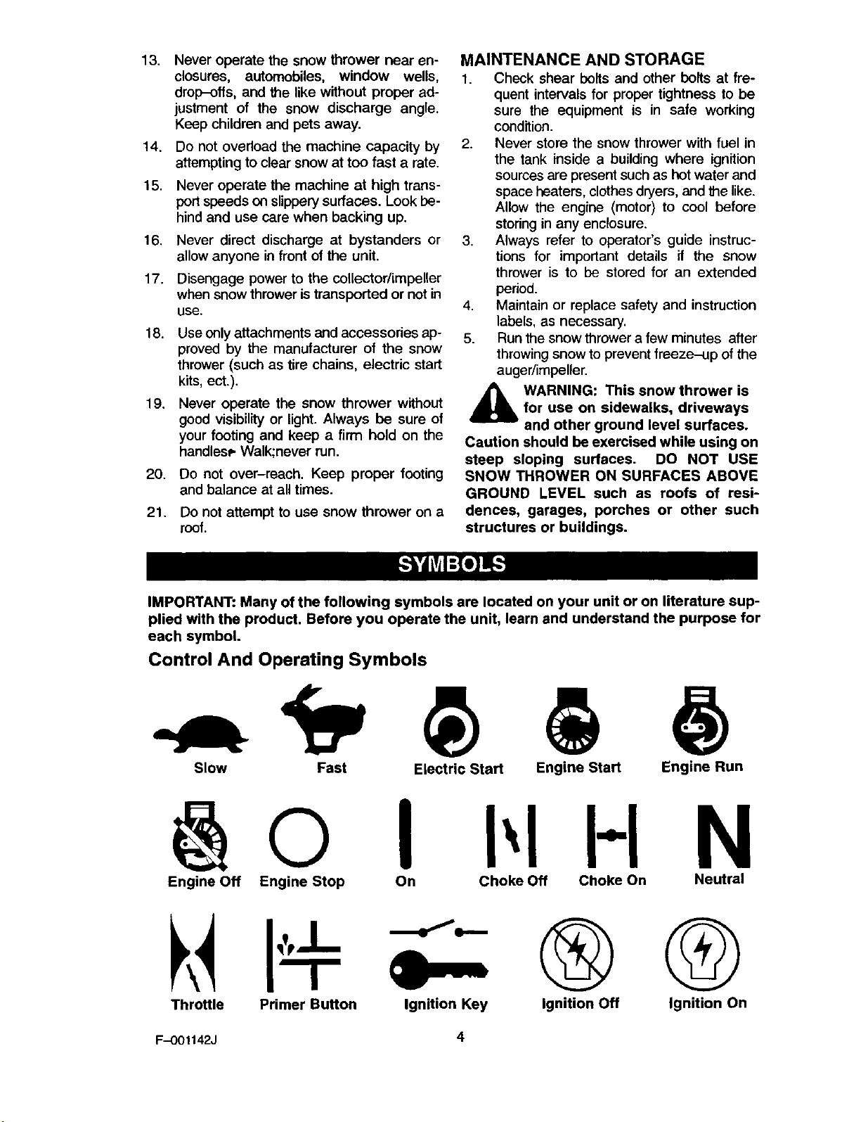
IMPORTANT: Many of the following symbols are located on your unit or on literature sup-
plied with the product. Before you operate the unit, learn and understand the purpose for
each symbol.
Control And Operating Symbols
Slow Fast Electric Start Engine Start Engine Run
I H N
Engine Off Engine Stop On Choke Off Choke On Neutral
G
Throttle Primer Button Ignition Key Ignition Off
Ignition On
F-001142J 4
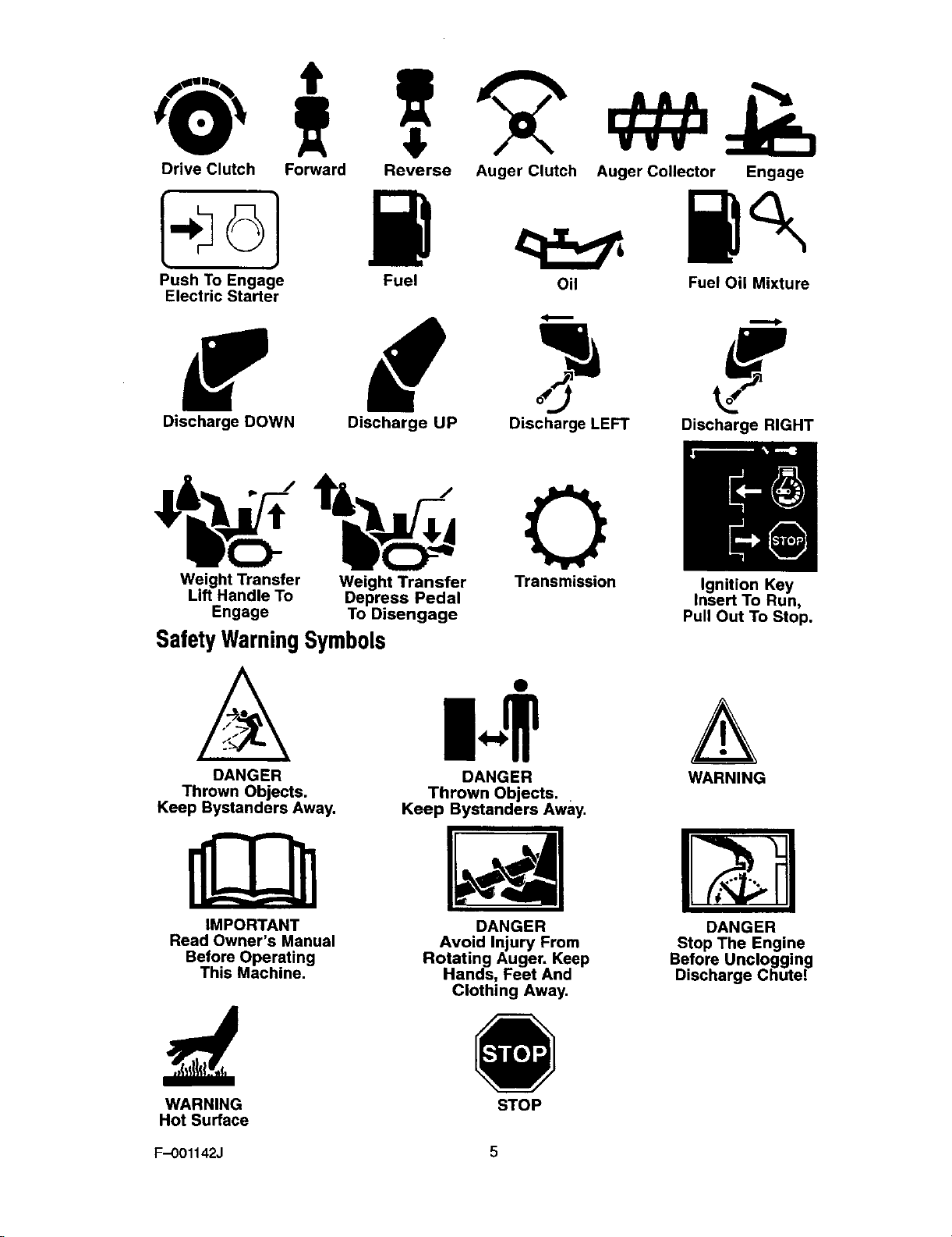
Drive Clutch Forward Reverse
k61 W
Auger Clutch
Auger Collector Engage
Push To Engage Fuel
Electric Starter
Oil Fuel Oil Mixture
f d
Discharge DOWN
Weight Transfer Weight Transfer Transmission Ignition Key
Lift Handle To Depress Pedal Insert To Run,
Engage To Disengage Pull Out To Stop.
SafetyWarningSymbols
Discharge UP
Discharge LEFT
Discharge RIGHT
)lm
MIni
A m..+
DANGER DANGER WARNING
Thrown Objects. Thrown Objects.
Keep Bystanders Away. Keep Bystanders Away.
IMPORTANT
Read Owner's Manual
Before Operating
This Machine.
WARNING STOP
Hot Surface
F.-O01142J 5
Rotating Auger. Keep
DANGER
Avoid Injury From
Hands, Feet And
Clothing Away.
DANGER
Stop The Engine
Before Uncloggin_
Discharge Chute.
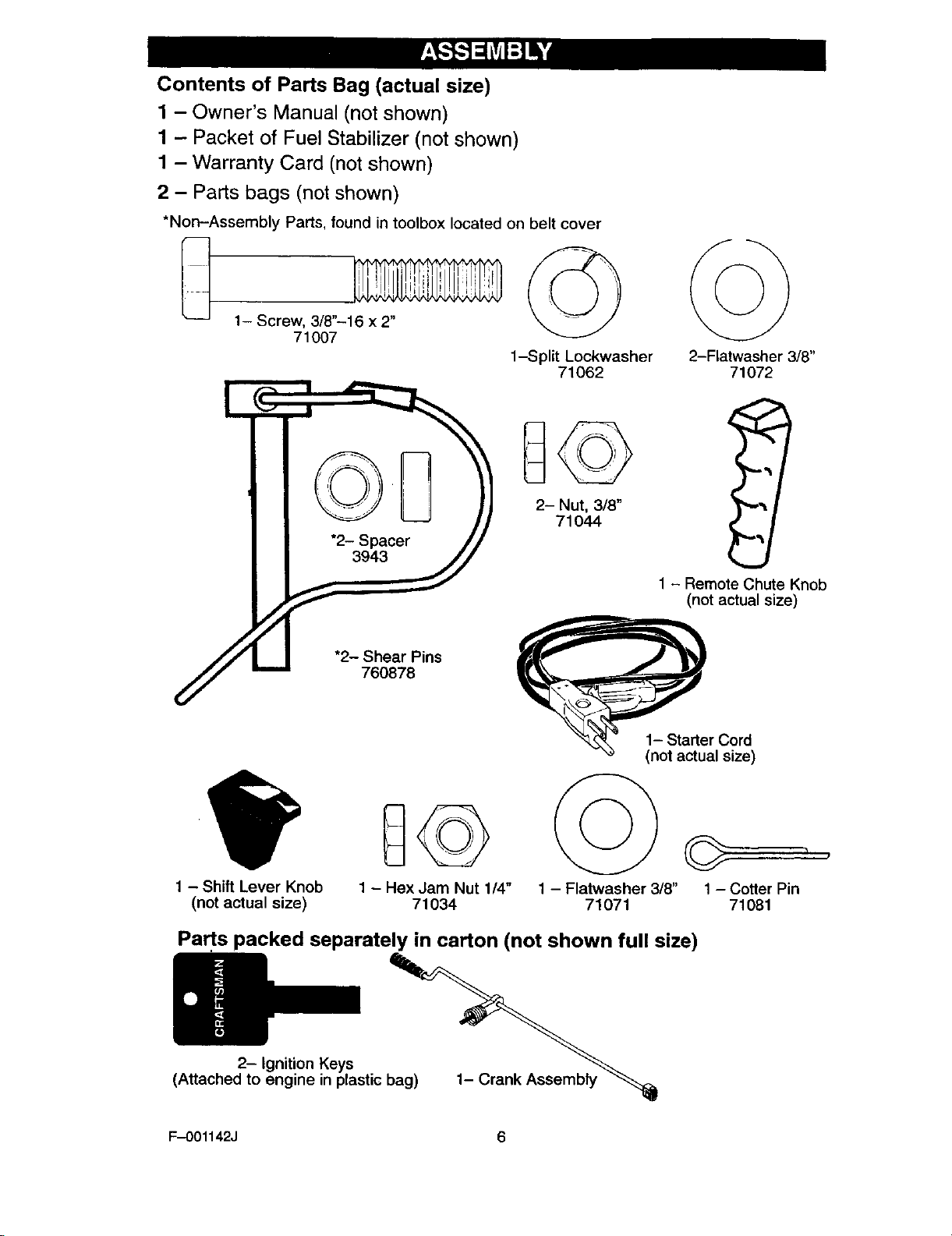
Contents of Parts Bag (actual size)
1 - Owner's Manual (not shown)
1 - Packet of Fuel Stabilizer (not shown)
1 - Warranty Card (not shown)
2 - Parts bags (not shown)
*Non-Assembly Parts, found in toolbox located on belt cover
1- Screw, 3/8"-16 x 2"
71007
_ 23SP,_cer_
_.] "2- S;_Pins
1-Split Lockwasher
71062
2-Flatwasher 3/8"
71072
1 - Remote Chute Knob
(not actual size)
e ,Os°re' /
1 - Shift Lever Knob
(not actual size)
1 - Hex Jam Nut 1/4"
71034
1 - Flatwasher 3/8"
71071
Parts packed separately in carton (not shown full size)
2- Ignition Keys
(Attached to engine in plastic bag)
F-OO1142J 6
1_ ran.Assemo,y
r
1 - Cotter Pin
71081
Read and follow the assembly and ad-
justment instructions for your snow
thrower. All fasteners are in the parts
bag. Do not discard any parts or materi-
al until the unit is assembled.
,_ WARNING: Before doing any
assembly or maintenance to
the snow thrower, remove the
wire from the spark plug.
NOTE: In this instruction book, left
and right describe the location of a
part from the operator's position be-
hind the unit.
Tools Required
1 Knife
1 Pliers
1 1/2 inch open end wrenches
1 9/16 inch open end wrenches
,_ WARNING: Always wear
safety glasses or eye
shields while assembling
snow thrower.
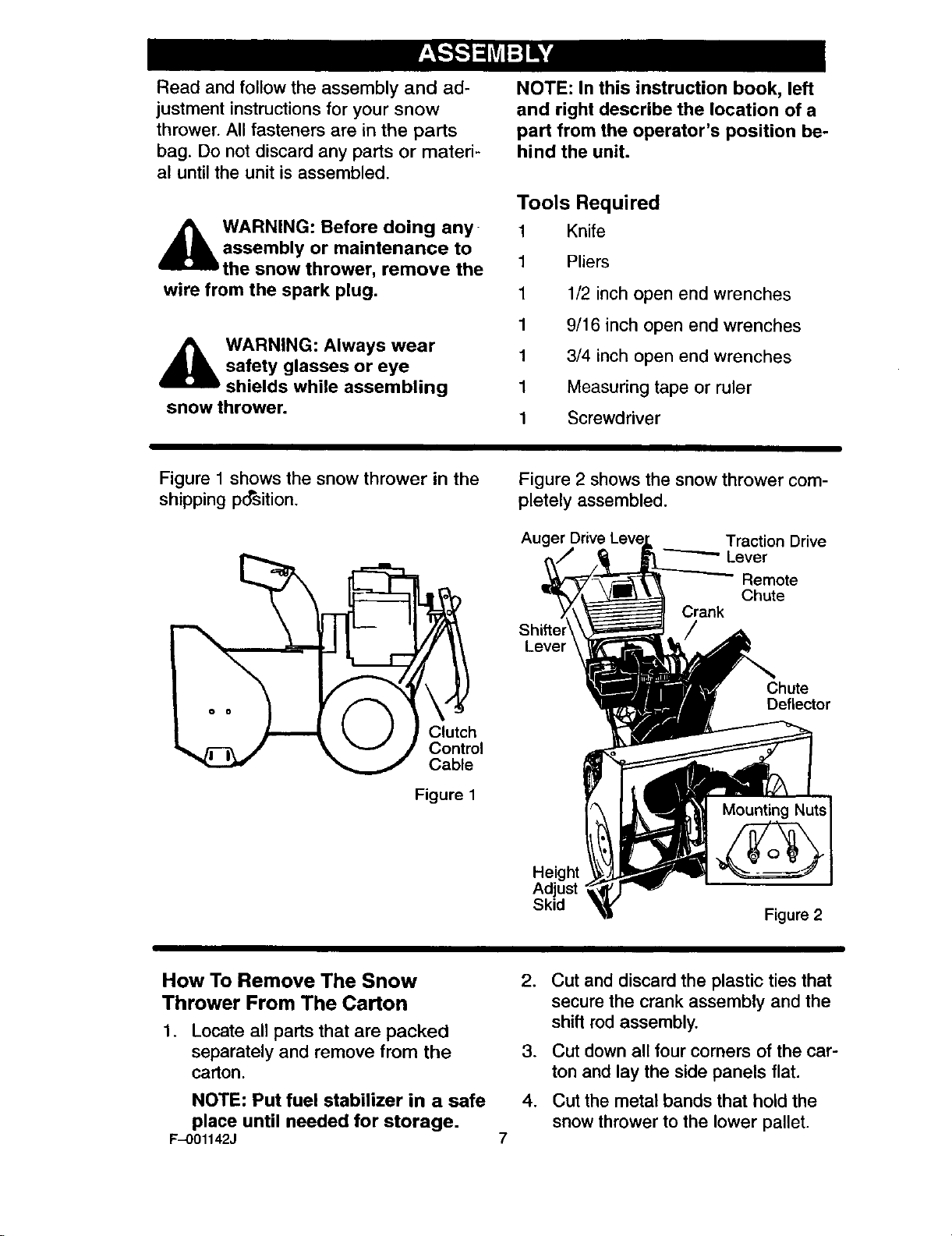
Figure 1 shows the snow thrower in the
shipping position.
_./i-_ J _ v / Control
_ Cable
Figure 1
1 3/4 inch open end wrenches
1 Measuring tape or ruler
1 Screwdriver
Figure 2 shows the snow thrower com-
pletely assembled.
Auger Traction Drive
"----'--" Lever
Remote
Chute
Crank
Lever
Chute
Deflector
How To Remove The Snow
Thrower From The Carton
1. Locate all parts that are packed
separately and remove from the
carton.
NOTE: Put fuel stabilizer in a safe
place until needed for storage.
F-O01142J
Height
Adjust
Skid
Figure 2
2. Cut and discard the plastic ties that
secure the crank assembly and the
shift rod assembly.
3. Cut down all four corners of the car-
ton and lay the side panels flat.
4. Cut the metal bands that hold the
snow thrower to the lower pallet.
.
Remove and discard all packing
material from around the snow
thrower.
.
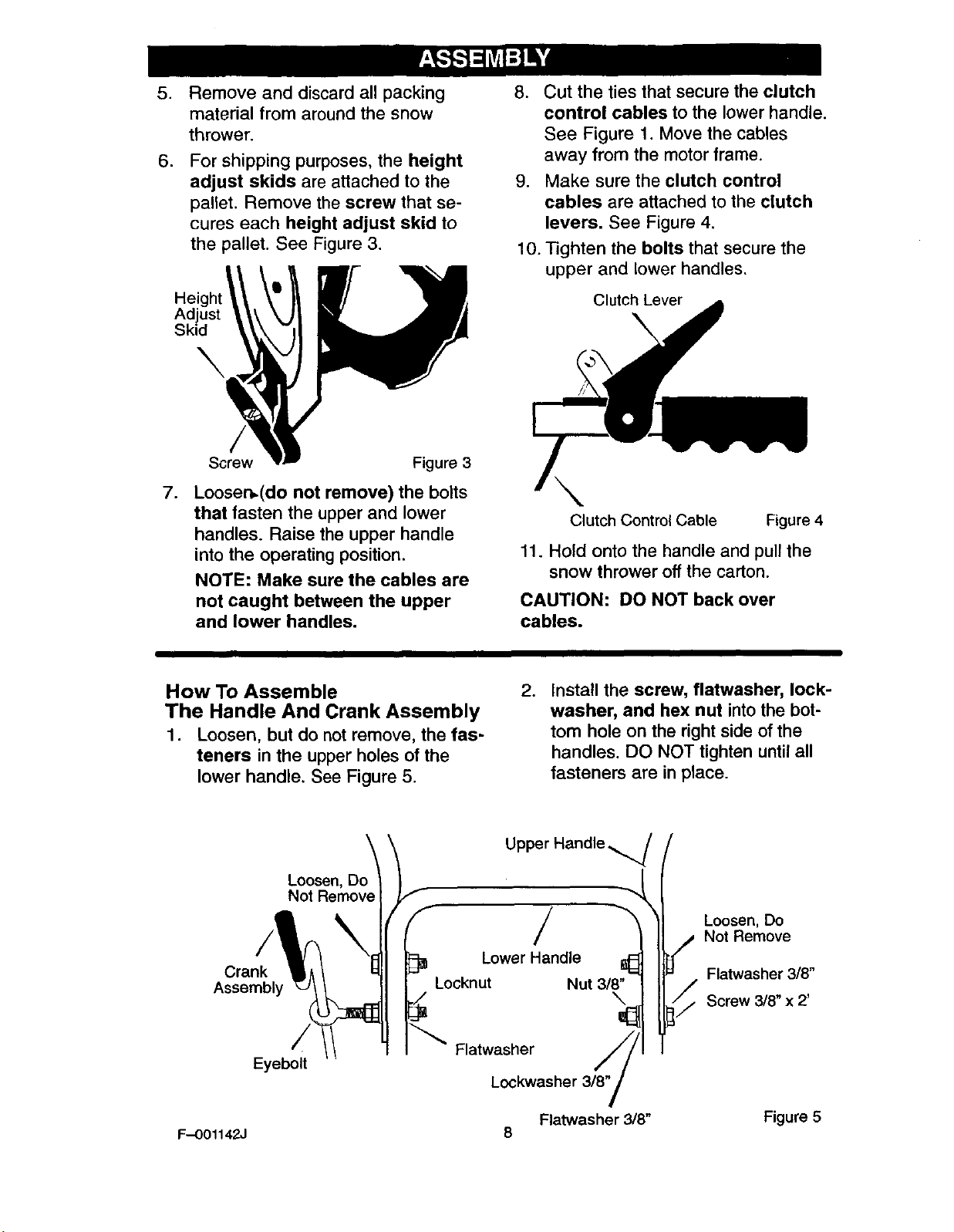
For shipping purposes, the height
adjust skids are attached to the
pallet. Remove the screw that se-
cures each height adjust skid to
the pallet. See Figure 3.
Adjust
Skid
Screw Figure 3
.
Loosen,(do not remove) the bolts
that fasten the upper and lower
handles. Raise the upper handle
into the operating position.
NOTE: Make sure the cables are
not caught between the upper
and lower handles.
8. Cut the ties that secure the clutch
control cables to the lower handle.
See Figure 1. Move the cables
away from the motor frame.
9. Make sure the clutch control
cables are attached to the clutch
levers. See Figure 4.
10. Tighten the bolts that secure the
upper and lower handles.
Clutch Lever
Clutch Control Cable Figure 4
11. Hold onto the handle and pull the
snow thrower off the carton.
CAUTION: DO NOT back over
cables.
How To Assemble
The Handle And Crank Assembly
1. Loosen, but do not remove, the fas-
teners in the upper holes of the
lower handle. See Figure 5.
Loosen, Do_
Not Remove I
Crank
Assembly
Locknut Nut 3/8"
Flatwasher
Eyeboff
F-001142J 8
. Install the screw, flatwasher, lock-
washer, and hex nut into the bot-
tom hole on the right side of the
handles. DO NOT tighten until all
fasteners are in place.
Upper Handle
LowerHandle ll_
Lockwasher 3/8"
Flatwasher 3/8" Figure 5
/
Loosen, Do
i/# Not Remove
Flatwasher 3/8"
Screw 3/8" x 2'
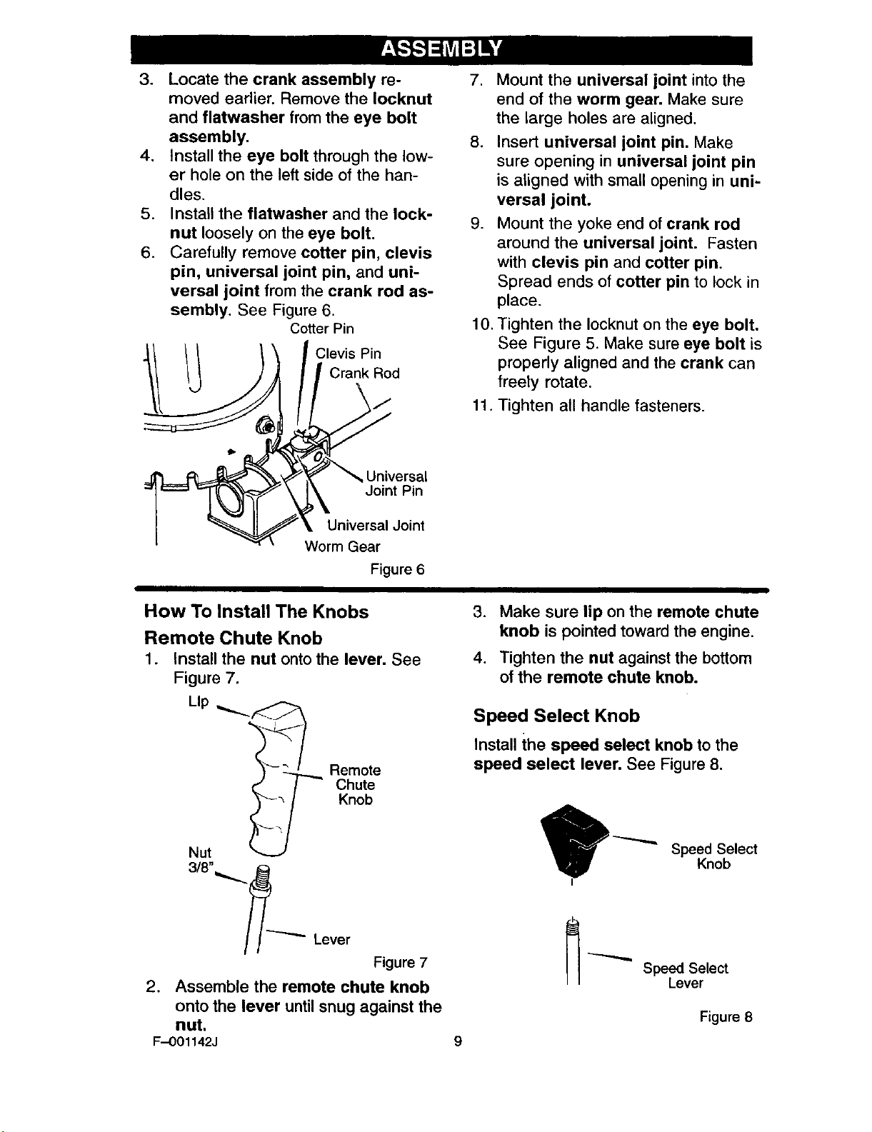
3. Locate the crank assembly re-
moved earlier. Remove the Iocknut
and flatwasher from the eye bolt
assembly.
4. Install the eye bolt through the low-
er hole on the left side of the han-
dles.
5. Install the flatwasher and the lock-
nut loosely on the eye bolt.
6. Carefully remove cotter pin, clevis
pin, universal joint pin, and uni-
versal joint from the crank rod as-
sembly. See Figure 6.
Cotter Pin
Clevis Pin
Crank Rod
tb
Universal
Joint Pin
.
Mount the universal joint into the
end of the worm gear. Make sure
the large holes are aligned.
8. Insert universal joint pin. Make
sure opening in universal joint pin
is aligned with small opening in uni-
versal joint.
9. Mount the yoke end of crank rod
around the universal joint. Fasten
with clevis pin and cotter pin.
Spread ends of cotter pin to lock in
place.
10.
Tighten the Iocknut on the eye bolt.
See Figure 5. Make sure eye bolt is
properly aligned and the crank can
freely rotate.
11. Tighten all handle fasteners.
Universal Joint
Worm Gear
Figure 6
How To Install The Knobs
Remote Chute Knob
1. Install the nut onto the lever. See
Figure 7.
_-- ,
Lip
Remote
Knob
Chute
Nut
3/8"_.._
Lever
3. Make sure lip on the remote chute
knob is pointed toward the engine.
4. Tighten the nut against the bottom
of the remote chute knob.
Speed Select Knob
Install the speed select knob to the
speed select lever. See Figure 8.
Speed Select
Knob
Figure 7
2. Assemble the remote chute knob
onto the lever until snug against the
nut.
F--001142J 9
Speed Select
Lever
Figure 8
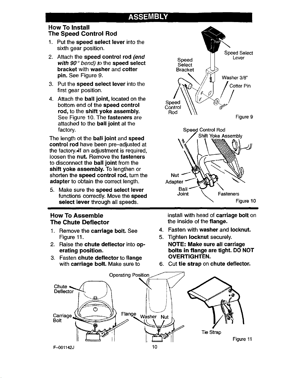
How To Install
The Speed Control Rod
1. Put the speed select lever into the
sixth gear position.
.
Attach the speed control rod (end
with 90 ° bend) to the speed select
bracket with washer and cotter
pin. See Figure 9.
3. Put the speed select lever into the
first gear position.
.
Attach the ball joint, located on the
bottom end of the speed control
rod, to the shift yoke assembly.
See Figure 10. The fasteners are
attached to the ball joint at the
factory.
The length ot the ball joint and speed
control rod have been pre-adjusted at
the factory.,,If an adjustment is required,
loosen the nut. Remove the fasteners
to disconnect the ball joint from the
shift yoke assembly. To lengthen or
shorten the speed control rod, turn the
adapter to obtain the correct length.
5. Make sure the speed select lever
functions correctly. Move the speed
select lever through all speeds.
_Speed Select
Speed ] [ Lever
Select
Bracket
Speed
Control
Rod
Speed Control Rod
Nut
Adapter
Ball
Joint _ Fasteners
Washer 3/8"
/
Figure 9
Assembly
Figure 10
How To Assemble
The Chute Deflector
1. Remove the carriage bolt. See
Figure 11.
2. Raise the chute deflector into op-
erating position.
3. Fasten chute deflector to flange
with carriage bolt. Make sure to
Chute
Operatin
Flang_,_ Washer Nut
Bolt
F-O01142J
install with head of carriage bolt on
the inside of the flange.
.
Fasten with washer and Iocknut.
5.
Tighten Iocknut securely.
NOTE: Make sure all carriage
bolts in flange are tight. DO NOT
OVERTIGHTEN.
6. Cut tie strap on chute deflector.
Tie Strap
lO
Figure 11
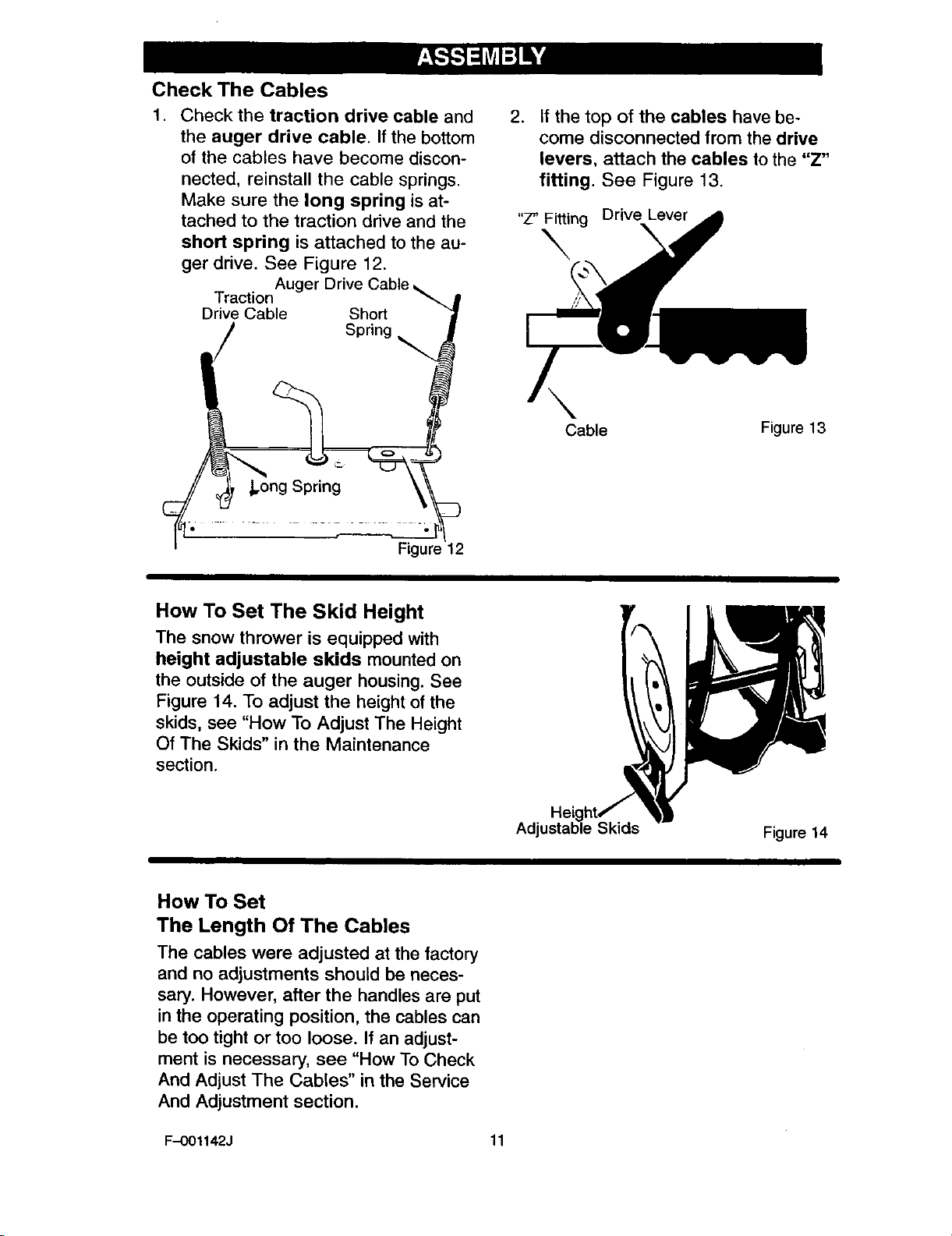
Check The Cables
1. Check the traction drive cable and
the auger drive cable. Ifthe bottom
of the cables have become discon-
nected, reinstall the cable springs.
Make sure the long spring is at-
tached to the traction drive and the
short spring is attached to the au-
ger drive. See Figure 12.
Auger Drive Cable
Traction _.+
Drive Cable Short
/ Spr+o0
.
If the top of the cables have be-
come disconnected from the drive
levers, attach the cables to the "Z"
fitting. See Figure 13.
"Z" Fitting Drive Lever
\
Cable Figure 13
I .............
How To Set The Skid Height
The snow thrower is equipped with
height adjustable skids mounted on
the outside of the auger housing. See
Figure 14. To adjust the height of the
skids, see "How To Adjust The Height
Of The Skids" in the Maintenance
section.
How To Set
The Length Of The Cables
The cables were adjusted at the factory
and no adjustments should be neces-
sary. However, after the handles are put
in the operating position, the cables can
be too tight or too loose. If an adjust-
ment is necessary, see "How To Check
And Adjust The Cables" in the Service
And Adjustment section.
Skids
Figure 14
F-0O1142J 11

_," CHECKLIST
Before you operate your new snow
thrower, to ensure that you receive the
best performance and satisfaction from
this quality product, please review the
following checklist:
_" All assembly instructions have been
completed.
P_ The discharge chute rotates freely.
1! No remaining loose parts in carton.
While learning how to use your snow
thrower, pay extra attention to the fol-
lowing important items:
P" Engine oil is at proper level.
_" Make sure gas tank is filled properly
wnthclean, fresh, unleaded gasoline•
P" Become familiar with all controls-
their location and function. Operate
controls before starting engine.
F-OO1142J 12

KNOW YOUR SNOW THROWER
READ THIS OWNER'S MANUAL AND SAFETY RULES BEFORE OPERATING
YOUR SNOW THROWER. Compare the illustrations with your SNOW THROWER
to familiarize yourself with the location of various controls and adjustments. Save
this manual for future reference,
Electric
Start
Button
Primer
Ignition Button
Key Switch
Box
Auger Drive Lever
Traction Drive Lever
Remote Chute
Control Lever
Crank Assembly
Chute Deflector
Discharge
Chute
Choke
Control Recoil
Throttle Starter
Control Handle
Height
Adjust
Skid
Auger Drive Lever - Starts and stops
the auger and impeller (snow gathering
and throwing)
Traction Drive Lever - Propels the
snow thrower forward and in reverse.
Speed Shifter Lever - Selects the
speed of the snow thrower (6 speeds for-
ward and 2 speeds reverse).
Crank Assembly - Changesthe direction
of snowthrowingthrough the dischargechute.
Chute Deflector - Changes thedistance
the snowis thrown.
Discharge Chute - Changes the height
and direction the snow is thrown.
Height Adjust Skid - Adjusts the ground
clearance of the auger housing.
Ignition Key - Must be inserted to start
the engine.
Recoil Starter Handle - Starts the en-
gine manually.
F-001142J 13
Shear Pin
Figure 15
Choke Control - Used to start a cold
engine.
Primer Button - Injects fuel directly into
the carburetor manifold for fast startsin
cold weather.
Remote Chute Control Lever - Push
forward to discharge snow high and far.
Pull remote lever back to discharge snow
down.
Throttle Control - Controls the engine
speed.
Electric Start Button - (if so equipped)
Used to start the engine using the 120 V elec-
tric starter.
Shear Pin -Shear pins are designed to
break (to protect the machine) if an ob-
iect becomes lodged in the auger hous-
ing.
Toolbox --spare shear pins and
spacers are located in toolbox.
The operation of any snow thrower can
result in foreign objects being thrown
into the eyes, which can result in se-
vere eye damage. Always wear safety
glasses or eye shields while operating
the snow thrower.
We recommend standard safety
glasses or a wide vision safety mask for
over your glasses.
_ ARNING: Read Owner's
Manual before operating
machine. Never direct dis-
charge toward bystanders. Stop the
engine before unclogging discharge
chute or auger housing and before
leaving the machine.
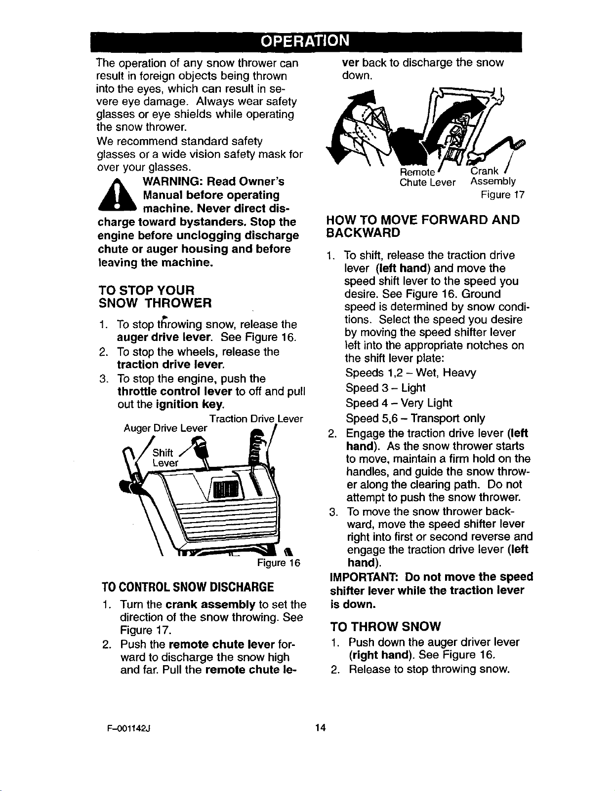
TO STOP YOUR
SNOW THROWER
1. To stop t_rowing snow, release the
auger drive lever. See Figure 16.
2. To stop the wheels, release the
traction drive lever.
3. To stop the engine, push the
throttle control lever to off and pull
out the ignition key.
Traction Drive Lever
Auger Drive Lever
Figure 16
TO CONTROLSNOW DISCHARGE
1. Turn the crank assembly to set the
direction of the snow throwing. See
Figure 17.
2. Push the remote chute lever for-
ward to discharge the snow high
and far. Pull the remote chute le-
ver back to discharge the snow
down.
Chute Lever Assembly
Figure 17
HOW TO MOVE FORWARD AND
BACKWARD
1. To shift, release the traction drive
lever (left hand) and move the
speed shift lever to the speed you
desire. See Figure 16. Ground
speed is determined by snow condi-
tions. Select the speed you desire
by moving the speed shifter lever
left into the appropriate notches on
the shift lever plate:
Speeds 1,2- Wet, Heavy
Speed 3 - Light
Speed 4 - Very Light
Speed 5,6 - Transport only
2. Engage the traction drive lever (left
hand). As the snow thrower starts
to move, maintain a firm hold on the
handles, and guide the snow throw-
er along the clearing path. Do not
attempt to push the snow thrower.
3. To move the snow thrower back-
ward, move the speed shifter lever
right into first or second reverse and
engage the traction drive lever (left
hand).
IMPORTANT: Do not move the speed
shifter lever while the traction lever
is down.
TO THROW SNOW
1. Push down the auger driver lever
(right hand). See Figure 16.
2. Release to stop throwing snow.
F-001142J 14
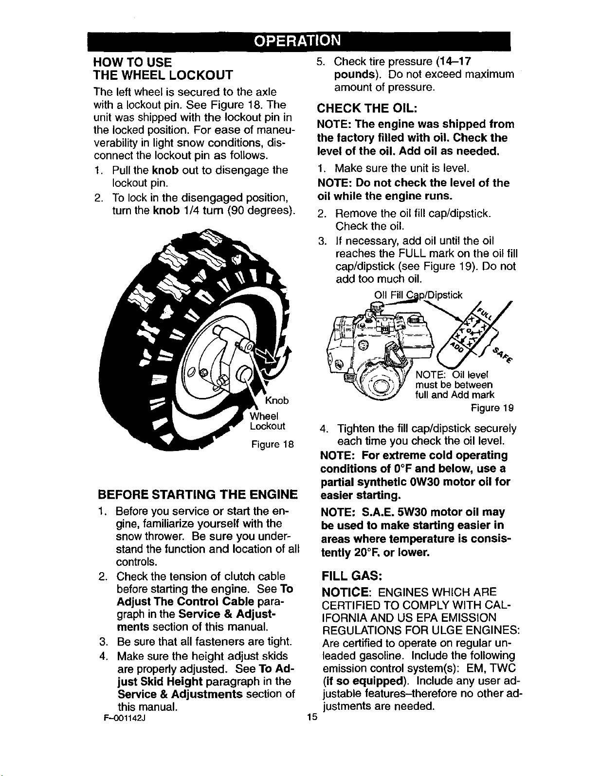
HOW TO USE
THE WHEEL LOCKOUT
The left wheel is secured to the axle
with a lockout pin. See Figure 18. The
unit was shipped with the lockout pin in
the locked position. For ease of maneu-
verability in light snow conditions, dis-
connect the lockout pin as follows.
1. Pull the knob out to disengage the
lockout pin.
2. To lock in the disengaged position,
turn the knob 1/4 turn (90 degrees).
5. Check tire pressure (14-17
pounds). Do not exceed maximum
amount of pressure.
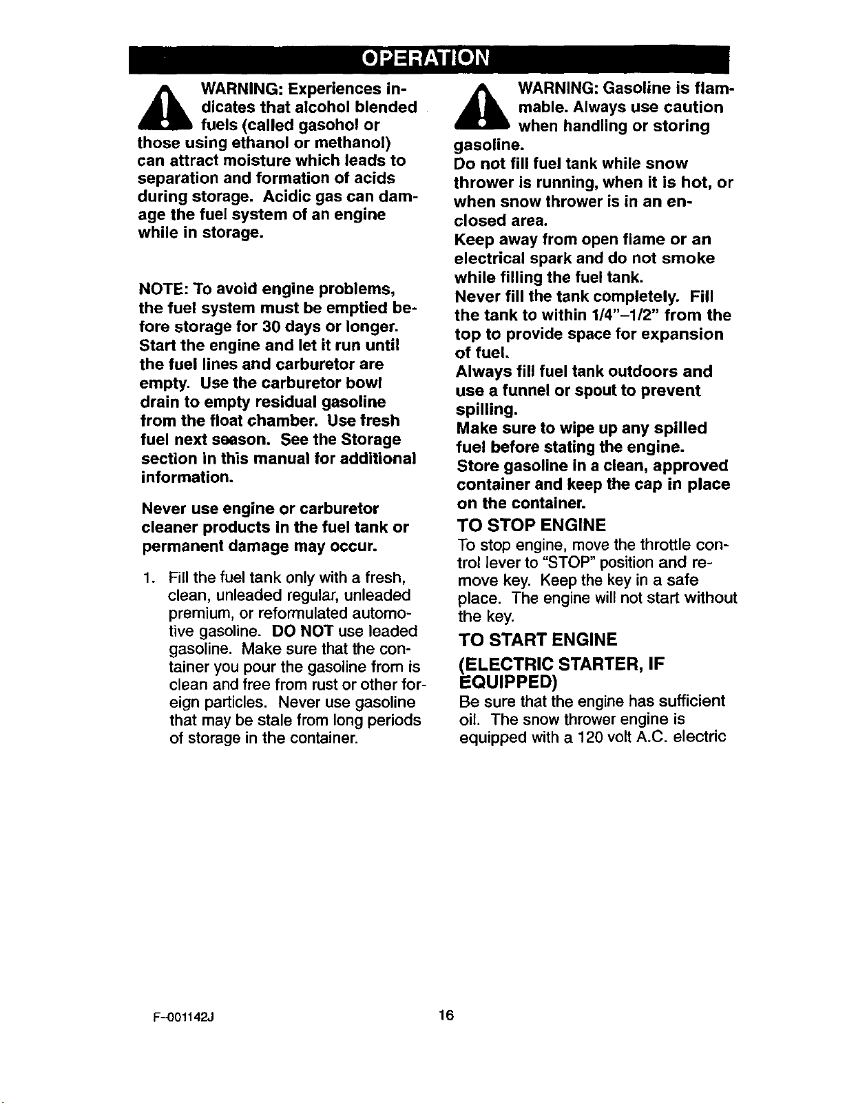
CHECK THE OIL:
NOTE: The engine was shipped from
the factory filled with oil. Check the
level of the oil. Add oil as needed.
1. Make sure the unit is level.
NOTE: Do not check the level of the
oil while the engine runs.
2. Remove the oilfill cap/dipstick.
Check the oil.
3. If necessary, add oil untilthe oil
reaches the FULL mark on the oil fill
cap/dipstick (see Figure 19). Do not
add too much oil.
p/Dipstick
Knob
Wheel
Lockout
Figure 18
BEFORE STARTING THE ENGINE
.
Before you service or start the en-
gine, familiarize yourself with the
snow thrower. Be sure you under-
stand the function and location of all
controls.
2. Check the tension of clutch cable
before starting the engine. See To
Adjust The Control Cable para-
graph in the Service & Adjust-
ments section of this manual.
,
Be sure that all fasteners are tight.
4.
Make sure the height adjust skids
are properly adjusted. See To Ad-
just Skid Height paragraph in the
Service & Adjustments section of
this manual.
F--OO1142J
fF_ 1_ NOTE: Oil level
/( _(_'-_J'_// must be between
"<'_'_._._._2 full and Add mark
Figure 19
4. Tighten the fill cap/dipstick securely
each time you check the oil level.
NOTE: For extreme cold operating
conditions of 0°F and below, use a
partial synthetic 0W30 motor oil for
easier starting.
NOTE: S.A.E. 5W30 motor oil may
be used to make starting easier in
areas where temperature is consis-
tently 20°1=.or lower.
FILL GAS:
NOTICE: ENGINES WHICH ARE
CERTIFIED TO COMPLY WITH CAL-
IFORNIA AND US EPA EMISSION
REGULATIONS FOR ULGE ENGINES:
Are certified to operate on regular un-
leaded gasoline. Include the following
emission control system(s): EM, TWC
(if so equipped). Include any user ad-
justable features-therefore no other ad-
justments are needed.
15
WARNING: Experiences in-
_ icates that alcohol blended
fuels (called gasohol or
those using ethanol or methanol)
can attract moisture which leads to
separation and formation of acids
during storage. Acidic gas can dam-
age the fuel system of an engine
while in storage.
NOTE: To avoid engine problems,
the fuel system must be emptied be-
fore storage for 30 days or longer.
Start the engine and let it run until
the fuel lines and carburetor are
empty. Use the carburetor bowl
drain to empty residual gasoline
from the float chamber. Use fresh
fuel next season. See the Storage
section in this manual for additional
information.
Never use engine or carburetor
cleaner products in the fuel tank or
permanent damage may occur.
.
Fill the fuel tank only with a fresh,
clean, unleaded regular, unleaded
premium, or reformulated automo-
tive gasoline. DO NOT use leaded
gasoline. Make sure that the con-
tainer you pour the gasoline from is
clean and free from rust or other for-
eign particles. Never use gasoline
that may be stale from long periods
of storage in the container.
,_ WARNING: Gasoline is flam-
mable. Always use caution
when handling or storing
gasoline.
Do not fill fuel tank while snow
thrower is running, when it is hot, or
when snow thrower is in an en-
closed area.
Keep away from open flame or an
electrical spark and do not smoke
while filling the fuel tank.
Never fill the tank completely. Fill
the tank to within 1/4"-112" from the
top to provide space for expansion
of fuel.
Always fill fuel tank outdoors and
use a funnel or spout to prevent
spilling.
Make sure to wipe up any spilled
fuel before stating the engine.
Store gasoline in a clean, approved
container and keep the cap in place
on the container.
TO STOP ENGINE
To stop engine, move the throttle con-
trol lever to "STOP" position and re-
move key. Keep the key in a safe
place. The engine will not start without
the key.
TO START ENGINE
(ELECTRIC STARTER, IF
EQUIPPED)
Be sure that the engine has sufficient
oil. The snow thrower engine is
equipped with a 120 volt A.C. electric
F-001142J 16
starter and recoil starter. Before start-
ing the engine, be certain that you have
read the following information.
_ll ARNING: The starter is
equipped with a three-wire
power cord and plug and is
designed to operate on 120 volt AC
household current.It must be proper-
ly grounded at all times to avoid the
possibility of electrical shock which
may be injurious to operator. Follow
all instructions carefully as set forth
in the "To Start Engine" section. De-
termine that your house wiring is a
three-wire grounded system. Ask a
licensed electrician if you are not
sure. If your house wire system is
not a three-wire system, do not use
this electric starter under any condi-
tions. If yo0r system is grounded
and a three-hole receptacle is not
available at the point your starter will
normally be used, one should be
installed by a licensed electrician.
when connecting 120 volt AC "Power
Cord", always connect the cord to
the Switch Box" on the engine first,
then plug the other end into the
three-hole grounded receptacle.
When disconnecting "Power cord",
always unplug the end in the three-
hole grounded receptacle first.
COLD START
1. Be sure auger drive and traction
drive levers are in the disengaged
(RELEASED) position.
.
Move throttle control to"FAST' posi-
tion.
3.
Remove the keys form the plastic
bag. Insert one key into ignition
slot. Make sure it snaps into place.
Do not turn key. Keep the second
key in a safe place.
4. Rotate choke knob clockwise to the
choke ON position.
5. Connect the power cord to the
switch box on the engine.
6. Plug other end of power cord into a
three-hole, grounded 120 VOLT, AC
F-001142J
receptacle. (See WARNING in this
section).
7. Push the primer button while cov-
ering the vent hole as follows: Re-
move finger from primer button
between primes.
Do not prime if temperature above
50 ° F (10° C).
Push two time if temperature is 50 °
F (10° C) to 15°F (-10 ° C).
Push four times if temperature is
below 15° F (-10 ° C).
8. Push down on the starter button
until the engine starts. Do not crank
for more than 10 seconds at a time.
This electric starter is thermally pro-
tected. If overheated it will stop au-
tomatically and can be restarted
only when it has cooled to a safe
temperature (a wait of about 5 to 10
minutes is required).
9. When the engine starts, release the
starter button and move choke le-
ver to "1/2 choke" position. When
engine runs smoothly, move choke
lever to "No Choke" Position.
10. Disconnect power cord from recep-
tacle, first, and then from switch
box.
NOTE: Allow the engine to warm
up for several minutes before
blowing snow in temperatures
below 0°F.
11.
Run engine at full throttle "FAST'
when throwing snow.
WARM START
If restarting a warm engine after a short
shutdown, leave choke at "OFF" and do
not push the primer button. If the en-
gine fails to start, follow the Cold Start
instructions.
TO START ENGINE
(RECOIL STARTER)
Be sure that the engine has sufficient
oil. The snow thrower engine is
equipped with a recoil starter. Before
starting the engine, be certain that you
have read the following information.
17
COLD START
.
Be sure auger drive and traction
drive levers are in the disengaged
(RELEASED) position.
.
Move throttle control to"FAST" posi-
tion.
3.
Remove the keys form the plastic
bag. Insert one key into ignition
slot. Make sure it snaps into place.
Do not turn key. Keep the second
key in a safe place.
4. Rotate choke knob clockwise to the
choke ON position.
5. Push the primer button while cov-
ering the vent hole as follows: Re-
move finger from primer button
between primes.
Do not prime if temperature above
50° F (10 ° C).
Push two time if temperature is 50°
F (10 ° C) to 15°F (-10 ° C).
Push four times if temperature is
below 15° F (-10 ° C).
6. Pull the starter handle rapidly. Do
not allow the handle to snap back,
but allow it to rewind slowly while
keeping a firm hold on the starter
handle.
.
As the engine warms up, move
choke lever to "1/2 choke" position.
When engine runs smoothly, move
choke lever to "No Choke" Posi-
tion.
NOTE: Allow the engine to warm
up for several minutes before
blowing snow in temperatures
below 0°E
.
Run engine at full throttle "FAST'
when throwing snow.
WARM START
If restarting a warm engine after a short
shutdown, leave choke at "OFF" and do
not push the primer button. If the en-
gine fails to start, follow the Cold Start
instructions.
FROZEN STARTER
If the starter is frozen and will not turn
engine:
1. Pull as much rope out of the starter
as possible.
2. Release the starter handle and let it
snap back against the starter.
If the engine stillfails to start, repeat the
two previous steps until the engine
starts. Then continue withthe direc-
tions for cold start.
To help prevent possible freeze-up of
recoil starter and engine controls, pro-
ceed as follows after each snow remov-
al job.
1. With the engine running, pull the
starter rope hard with a continuous
full arm stroke three or four times.
Pulling of starter rope will produce a
loud clattering sound. This is not
harmful to the engine or starter.
2. With the engine not running, wipe all
snow and moisture from the carbu-
retor cover in area of control levers.
Also move throttle control, choke
control, and starter handle several
times.
,_ WARNING: Never run en-
gine indoors or in enclosed,
poorly ventilated areas. En-
gine exhaust contains CARBON
MONOXIDE, AN ODORLESS AND
DEADLY GAS. Keep hands, feet,
hair and loose clothing away from
any moving parts on engine and
snow thrower.
The temperature of muffler and
nearby areas may exceed 150°F.
Avoid these areas.
DO NOT allow children or young
teenagers to operate or be near
snow thrower while it is operating.
F-001142J 18
 Loading...