

Page 1
CAUTION: Before using this
product, read this manual
and follow all of its Safety
Rules and Operating
Instructions.
Operator’s Manual
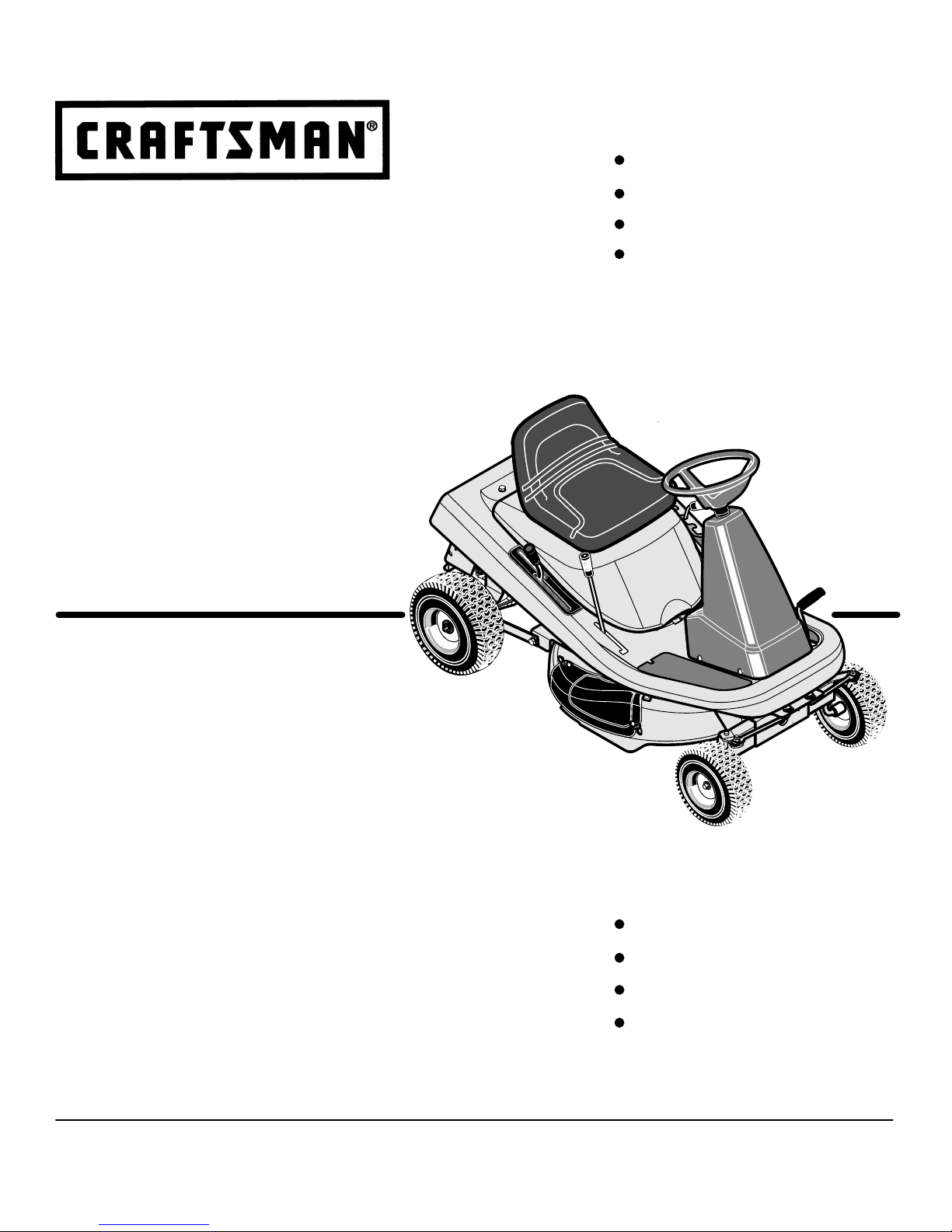
Mid-Engine Rider
13.5 HP. Electric Start
30” Mower / Mulcher
Hydrostatic Drive
Sears, Roebuck and Co., Hoffman Estates, IL. 60179 U.S.A.
www.sears.com/craftsman
Tractor cortacésped con motor
situado detrás del asiento
Arranque eléctrico de 13,5 caballos
Cortacésped / trituradora de 76 cm.
Transmisión hidrostática
PRECAUCIÓN: Antes de usar este
producto, lea este manual y siga
todas las reglas de seguridad e
instrucciones de operación.
Manual del usario
(página 65)
Operation
Maintenance
Parts
Safety
Operación
Mantenimiento
Piezas
Seguridad
400150 11/08
Model 536.270321
Modelo 536.270321
Page 2

2
TABLE OF CONTENTS
WARRANTY 2. . . . . . . . . . . . . . . . . . . . . . . . . . . . . . . . . . . .
PRODUCT SPECIFICATIONS 3. . . . . . . . . . . . . . . . . . . . .
SAFETY RULES 4. . . . . . . . . . . . . . . . . . . . . . . . . . . . . . . . .
PREPARATION 7. . . . . . . . . . . . . . . . . . . . . . . . . . . . . . . . . .
OPERATION 10. . . . . . . . . . . . . . . . . . . . . . . . . . . . . . . . . . . .
MAINTENANCE 22. . . . . . . . . . . . . . . . . . . . . . . . . . . . . . . . .
SERVICE AND ADJUSTMENT 28. . . . . . . . . . . . . . . . . . . .
TROUBLESHOOTING CHART 36. . . . . . . . . . . . . . . . . . . .
SLOPE GUIDE 39. . . . . . . . . . . . . . . . . . . . . . . . . . . . . . . . . .
REPAIR PARTS 40. . . . . . . . . . . . . . . . . . . . . . . . . . . . . . . . .
LIMITED WARRANTY ON CRAFTSMAN RIDING EQUIPMENT
For two (2) years from the date of purchase, if this Craftsman Riding Equipment is maintained, lubricated and tuned up
according to the instructions in the owner’s manual, Sears will repair or replace free of charge any parts that are found to be
defective in material or workmanship according to the guidelines of coverage listed below.
Sears will also provide free labor for these applicable warranted parts for the two full years. During the first 30 days of purchase,
there will be no charges to service the product at your home for issues covered by this warranty. (See exclusions below).
For your convenience, IN HOME warranty service will still be available after the first 30 days of purchase, but a trip charge will
apply. This charge will be waived if the Craftsman product is dropped off at an authorized Sears location. For the nearest
authorized Sears location, please call 1-800-4-MY-HOMER. This warranty applies only while this product is within the United
States.
This Warranty does not cover:
• Expendable items which become worn during normal use, including but not limited to blades, spark plugs, air cleaners,
belts, and oil filters.
• Standard Maintenance Servicing, oil changes, or tune-ups
• Tire replacement or repair caused by punctures from outside objects, such as nails, thorns, stumps or glass.
• Repairs necessary because of operator abuse, including but not limited to, damage caused by towing objects beyond the
capability of the riding equipment, impacting objects that bend the frame or crankshaft, or over-speeding the engine.
• Repairs necessary because of operator negligence, including but not limited to, electrical and mechanical damage caused
by improper storage, failure to use the proper grade and amount of engine oil, failure to keep the deck clear of flammable
debris, or failure to maintain the equipment according to the instructions contained in the owner’s manual.
• Engine (fuel system) cleaning or repairs caused by fuel determined to be contaminated or oxidized (stale). In general, fuel
should be used within 30 days of its purchase date.
• Normal deterioration and wear of the exterior finishes, or product label replacement.
• Riding equipment used for commercial or rental purposes.
LIMITED WARRANTY ON BATTERY
For ninety (90) days from date of purchase, if any battery included with this riding equipment proves defective in material or
workmanship and our testing determines the battery will not hold a charge, Sears will replace the battery at no charge. During
the first 30 days of purchase, there will be no charges to replace the battery at your home. After the first 30 days, for your convenience, IN-HOME warranty service will still be available but a trip charge will apply. This charge will be waived if the Craftsman
product is dropped off at an authorized Sears location. For the nearest authorized Sears location, please call 1-800-4-MYHOMER. This Warranty applies only while this product is within the United States. This warranty gives you specific legal rights,
and you may also have other rights, which vary, from state to state.
Sears, Roebuck and Co., Dept. 817WA, Hoffman Estates, IL 60179
400150
Page 3
3
Congratulations on your purchase of a Craftsman Mid-Engine
Rider. It has been designed, engineered and manufactured to
give you the best possible dependability and performance.
If you experience any problems you cannot easily remedy, please
see your nearest Sears Service Center. We have competent, well
trained technicians and the proper tools to service or repair this
unit.
Please read and keep this manual. The instructions will enable
you to assemble and maintain your unit properly. Always observe
the “Safety Rules”.
PRODUCT SPECIFICATIONS
Engine 13.5 HP.. . . . . . . . . . . . . . . . . .
Bore 3.44 in. (87.31 mm). . . . . . . . . . . . . . . . . .
Stroke 3.06 in. (77.78 mm). . . . . . . . . . . . . . . .
Displacement 28.42 cu. in. (466 cc). . . . . . . . .
Armature air gap 0.010-0.014 in. (0.25-0.36 mm). . . . . .
Valve Clearance with valve springs installed and piston
0.25 in. (6 mm) past top dead center (check when engine
is cold)
Intake 0.003-0.005 in. (0.08-0.13 mm). . . . . . . . . . . . . . . . .
Exhaust 0.005-0.007 in. (0.13-0.18 mm). . . . . . . . . . . . . . .
Charging System 3 amperes at 3600 rpm. . . . . . . . .
Fuel Tank SIze 1.1 gallon. . . . . . . . . . .
Type of Fuel Unleaded Regular. . . . . . . . . . . . .
Oil Capacity 48 ounces (3 pints). . . . . . . . . . . . . .
Oil Type Above 32 degrees SAE 30. . . . . . . . . . . . . . . . .
Below 32 degrees SAE 5W30. . . . . . . . . . . . . . . . . . . . . . . . . .
Spark Plug (Gap 0.030”) Champion RJ4C. .
Tire Air Pressure Front 22 psi (See tire sidewall). . . . . . . . .
Tire Air Pressure Rear 14 psi (See tire sidewall). . . . . . . . .
Drive System Hydrostatic. . . . . . . . . . . .
Ground Speed Range Forward 5.0 mph. . . . .
Reverse 2.5 mph. . . . . . . . . . . . . . . . . . . . . . . . . .
Tilt Seat Access to engine and battery.. . . . . . . . . . . . . . . . .
Mower Housing Floating suspension, one blade.. . . . . . . . . .
Cutting Height 6 positions from 1
1
/2 to 4 inches.. . . . . . . . . . .
Blade Nut Torque 30 foot-pounds (ft-lbs). . . . . . . . .
Power Ratings: The power ratings for an individual engine mod-
el are initially developed by starting with SAE (Society of Automotive Engineers) code J1940 (Small Engine Power & Torque
Rating Procedure) (Revision 2002-05). Given both the wide array
of products on which our engines are placed, and the variety of
environmental issues applicable to operating the equipment, it
may be that the engine you have purchased will not develop the
rated horsepower when used in a piece of power equipment (actual “on-site” power). This difference is due to a variety of factors
including, but not limited to, the following: differences in altitude,
temperature, barometric pressure, humidity, fuel, engine lubrication, maximum governed engine speed, individual engine to engine variability, design of the particular piece of power equipment,
the manner in which the engine is operated, engine run-in to reduce friction and clean out of combustion chambers, adjustments
to the valves and carburetor, and other factors. The power ratings
may also be adjusted based on comparisons to other similar engines utilized in similar applications, and will therefore not necessarily match the values derived using the foregoing codes.
NOTE: Actual sustained horsepower will likely be lower due
to operating limitations and environmental factors.
Craftsman Mid-Engine Rider
Record in the space below the serial number and the date
of purchase of this unit.
The model number and serial number are found on a decal
attached to the unit.
Serial Number:
Date of Purchase:
Keep these numbers for future reference.
REPAIR PROTECTION AGREEMENT
A Repair Protection Agreement is available on this unit. See the
nearest Sears Store for information.
Engine Exhaust, some of its constituents, and
certain vehicle components contain or emit
chemicals known to the State of California to
cause cancer and birth defects or other reproductive harm.
Battery posts, terminals and related accessories contain lead and lead compounds, chemicals known to the State of California to cause
cancer and birth defects or other reproductive
harm. WASH HANDS AFTER HANDLING.
NOTE: This unit is equipped with an internal combustion engine
and must not be used on or near any unimproved forest-covered,
brush-covered or grass-covered land unless the engine’s exhaust
system is equipped with a spark arrester meeting applicable local
or state laws (if any). If a spark arrester is used, it must be
maintained in effective working order by the operator.
In the State of California, the above is required by law (Section
4442 of the California Public Resources Code). Other states may
have similar laws. Federal laws apply on federal lands. See a
Sears Service Center for a spark arrester for the muffler.
In some areas, local law requires the use of a resistor spark plug
to control the ignition signals. See a Sears Service Center for a
resistor spark plug for the engine.
In the state of California, Model Series 280000 engines are certified by the California Air Resources Board to meet emissions
standards for 125 hours. Such certification does not grant the
purchaser, owner or operator of this engine any additional warranties with respect to the performance or operational life of this
engine. This engine is warranted solely according to the product
and emissions warranties stated elsewhere in this manual.
270321
400150
Model Number: 536.
Page 4

SAFETY RULES
4
Safe Operation Practices for Ride−on Mowers
The safety symbol is used to identify safety information about hazards that can result in personal injury. A signal word (DANGER, WARNING, or CAUTION) is used with the alert symbol to indicate the likelihood and the potential severity of injury. In
addition, a hazard symbol may be used to represent the type of hazard.
DANGER indicates a hazard which, if not avoided, will result in death or serious injury.
WARNING indicates a hazard which, if not avoided, could result in death or serious injury.
CAUTION indicates a hazard which, if not avoided, might result in minor or moderate injury.
CAUTION when used without the alert symbol, indicates a situation that could result in damage to the engine.
WARNING: This cutting machine is capable of amputating hands and feet and throwing objects. Failure to observe the
following safety instructions could result in serious injury or death.
I. General operation
1. Read, understand and follow all instructions in the Instruction
Book, on the machine, the engine and with any attachments before starting.
2. Only allow responsible adults, who are familiar with the instruc-
tions, to operate the machine.
3. Clear the area of objects such as rocks, toys, wire, etc., which
could be picked up and thrown by the blade.
4. Be sure the area is clear of other people before mowing. Stop
the machine if anyone enters the area.
5. Never carry passengers.
6. Turn off power to the blades or any attachments before backing
up. Do not mow in reverse unless absolutely necessary. Always
look down and behind before and while backing.
7. Be aware of the mower discharge direction and do not point it
at anyone. Do not operate the mower without either the entire
grass bagger or the mower guard in place.
8. Slow down before turning.
9. Never leave a machine unattended with the engine running. Al-
ways turn off the blade(s), set the parking brake, stop the engine and remove the key before dismounting.
10. Turn off power to attachment(s) when transporting or not in use.
Turn off the blade(s) when not mowing.
11. Stop the engine before removing the grass bagger or unclog-
ging the chute.
12. Mow only in daylight or good artificial light.
13. Do not operate the machine while under the influence of alcohol
or drugs or when very tired.
14. Watch for traffic when operating near or crossing roadways.
15. Use extra caution when loading or unloading the machine into
a trailer or truck.
16. Disengage all attachment clutches and shift into Neutral before
attempting to start the engine.
17. Always wear goggles, safety glasses, or an eye shield when
you operate the unit to protect your eyes from foreign objects
that can be thrown from the unit. Always wear eye protection
when you make an adjustment or repair to the machine.
18. Use care when pulling loads or using heavy equipment.
a. Use only approved drawbar hitch points.
b. Limit loads to those you can safely control.
c. Do not turn sharply. Use care when backing.
d. Use counterweights or wheel weights when suggested in the
Instruction Book.
19. Do not operate this machine if you are taking drugs or other medication which can cause drowsiness or affect your ability to operate this machine.
20. Do not use this machine if you are mentally or physically unable
to operate this machine safely.
21. Data indicates that operators, age 60 years and above, are involved in a large percentage of riding mower related injuries.
These operators should evaluate their ability to operate a riding
mower safely enough to protect themselves and others from
serious injury.
II. Slope operation
Slopes and rough terrain are major factors related to loss−of−con-
trol and tip−over accidents, which can result in severe injury or
death. ALL slopes require extra caution. If you cannot back up the
slope or if you feel uneasy on the slope, do not mow it. See the
“Slope Guide” in the back of this book to check for safe operation.
DO
1. Mow up and down slopes, not across.
2. Remove obstacles such as rocks, limbs, etc...
3. Watch for holes, ruts or bumps. Uneven terrain could overturn
the machine. Tall grass can hide obstacles.
4. Follow the manufacturer’s recommendations for wheel weights
or counterweights to improve stability.
5. Use extra care with grass baggers or other attachments, they
can change the stability of the machine.
6. Keep all movement on the slopes slow and gradual. Do not
make sudden changes in speed or direction.
7. Avoid starting or stopping on a slope. If tires lose traction, turn
off the blades and proceed slowly straight down the slope.
DO NOT
1. Do not turn on slopes unless absolutely necessary, then only
turn slowly and gradually downhill, if possible.
2. Do not mow drop−offs, ditches or embankments. A wheel over
the edge or an edge caving in could cause a sudden overturn
and an injury or death.
3. Do not mow on wet grass. Reduced traction could cause sliding.
4. Do not try to stabilize the machine by putting your foot on the
ground.
5. Do not use a grass bagger or other rear mounted accessories
on steep slopes (greater than 10 degrees).
400150
Page 5

SAFETY RULES
5
III. Children
Tragic accidents can occur if the operator is not alert to the presence
of children. Children are often attracted to the machine and the
mowing activity. NEVER assume that children will remain where you
last saw them.
1. Keep children out of the mowing area and in the watchful care
of another responsible adult.
2. Be alert and turn the engine off if children enter the area.
3. Before and when backing, look behind and down for small
children.
4. Never carry children or any passengers, even with the blades
off. They may fall off and be seriously injured or interfere with
the safe operation of the machine.
5. Never allow children to operate the machine. Instruct children
in the potential dangers of the machine.
6. Use extra care when approaching blind corners, shrubs, trees
or other objects that may obscure vision.
IV. Towing
1. Tow only with a machine that has a hitch designed for towing.
Do not attach towed equipment except at the hitch point.
2. Follow the manufacture’s recommendation for weight limits for
towed equipment and towing on slopes.
3. Never allow children or others in or on towed equipment.
4. On slopes, the weight of the towed equipment may cause loss
of traction and loss of control.
5. Travel slowly and allow extra distance to stop.
V. Safe Handling Of Gasoline
To avoid personal injury or property damage, use extreme care in
handling gasoline. Gasoline is extremely flammable and the vapors
are explosive.
1. Extinguish all cigarettes, cigars, pipes, and other sources of
ignition.
2. Use only an approved gasoline container.
3. Never remove gas cap or add fuel with the engine running. Allow engine to cool before refueling.
4. Never fuel the machine indoors.
5. Never store the machine or fuel container where there is an
open flame, spark, or pilot light such as on a water heater or other appliances.
6. Never fill containers inside a vehicle or on a truck or trailer bed
with a plastic liner. Always place containers on the ground away
from your vehicle before filling.
7. Remove gas-powered equipment from the truck or trailer and
refuel it on the ground. If this is not possible, then refuel such
equipment with a portable container, rather than from a gasoline dispenser nozzle.
8. Keep the nozzle in contact with the rim of the fuel tank or container opening at all times until the fueling is complete. Do not
use a nozzle lock-open device.
9. If fuel is spilled on clothing, change clothing immediately.
10. Never overfill fuel tank. Replace gas cap and tighten securely.
VI. Service
1. Use extra care when handling gasoline and other fuels. Fuels
are flammable and the vapors are explosive.
a. Use only an approved container.
b. Never remove the gas cap or add fuel with the engine run-
ning. Allow the engine to cool for several minutes before
refueling. Do not smoke.
c. Never refuel the machine indoors or near appliances with
pilot lights, heaters, or other ignition sources.
d. Never store the machine with fuel in the tank or fuel con-
tainer inside where there is an open flame, such as a water
heater.
2. Never start or run the engine inside a closed area.
a. Make sure that spark plug, muffler, fuel cap and air cleaner
are in place.
b. Do not crank engine with spark plug removed.
c. If fuel spills, wait until it evaporates before starting engine.
d. Do not start if there is LP or natural gas leakage in the area.
3. Keep all nuts and bolts, especially the blade attachment nuts
tight. Frequently check the blade(s) for wear or damage such
as cracks and nicks. A blade that is bent or damaged must be
immediately replaced with an original equipment blade from an
authorized service dealer. For safety, replace the blade every
two years. Keep the equipment in good condition.
4. Never tamper with the safety devices. Check their proper operation regularly.
5. To reduce fire hazards, keep the machine free of grass, leaves
or other debris build−up. Clean up oil or fuel spills. Allow the machine to cool before storing.
a. Allow muffler and engine areas to cool before touching.
6. Stop and inspect the equipment if you strike an object. Repair,
if necessary, before restarting.
7. Never make adjustments or repairs with the engine running.
The carburetor can be adjusted with the engine running. Do not
change the engine governor settings or over−speed the engine.
8. Grass bagger components are subject to wear, damage and
deterioration, which could expose moving parts or allow objects
to be thrown. For storage, always make sure the grass bag is
empty. Frequently check components and replace with manufacturer’s recommended parts when necessary.
9. Mower blade(s) are sharp and can cut. Wrap the blade(s) or
wear gloves and use extra caution when servicing them or the
blade housing area.
10. Check the brake operation frequently. Adjust and service as required.
11. Wait for all movement to stop before servicing any part of the
unit.
RESPONSIBILITY OF THE OWNER
Environmental Awareness
• Do not fill the engine’s fuel tank completely full.
• Drain fuel for off−season storage.
• Use only unleaded gasoline.
• Service the air cleaner regularly.
• Change oil regularly. Use oil rated 30 in the summer.
• Tune−up the engine regularly.
• Keep equipment in efficient operating condition.
• Dispose of used engine oil properly.
400150
Page 6
SAFETY RULES
6
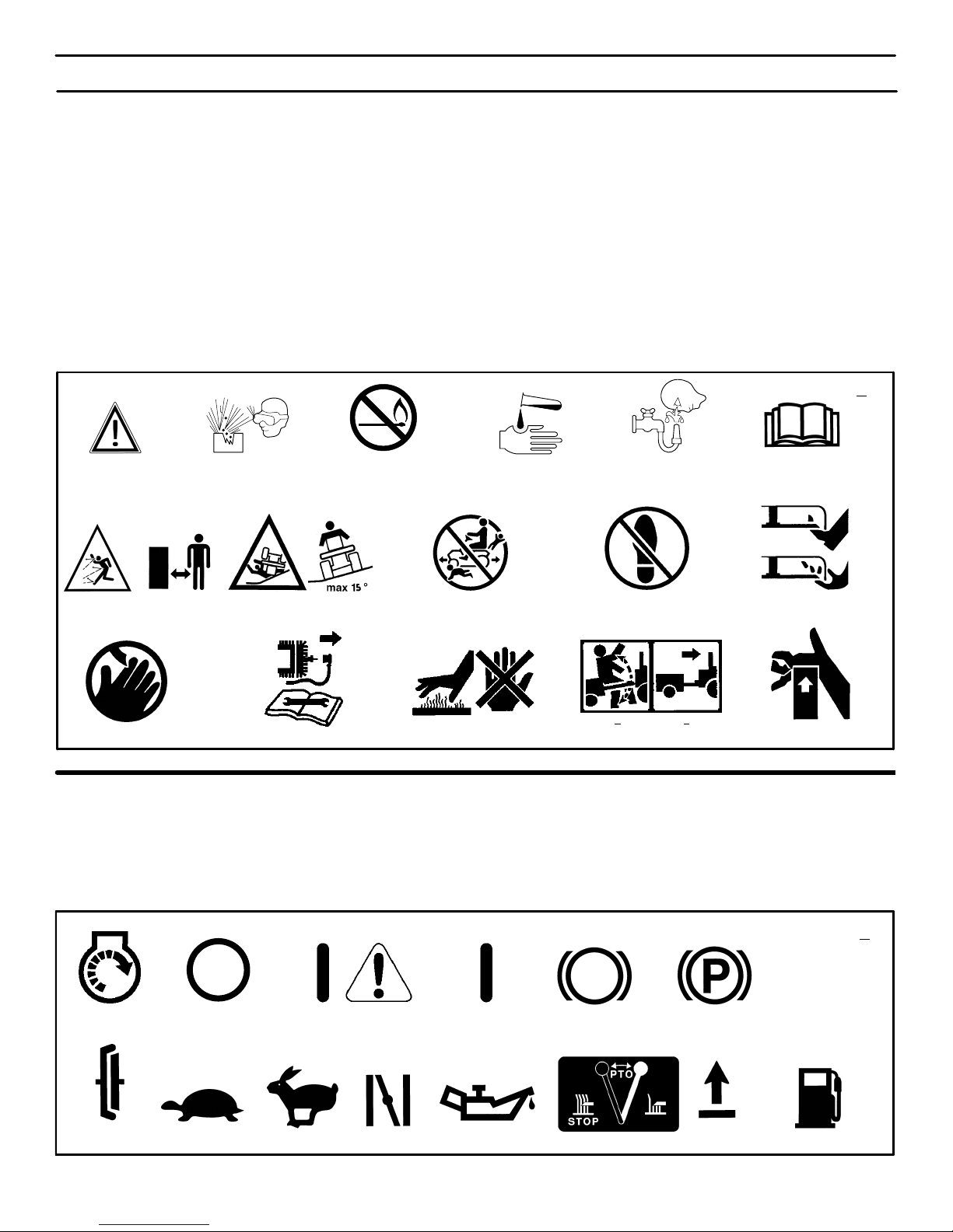
INTERNATIONAL PICTORIALS
IMPORTANT: Some of the following pictorials are located on your unit or on
literature supplied with the product. Before you operate the unit, learn and understand the purpose for each pictorial.
Safety Warning Pictorials
1 Warning
2 Shield Eyes. Explosive Gases Can
Cause Blindness Or Injury.
3 No Sparks, Flames or Smoking.
4 Sulphuric Acid Can Cause Blindness
Or Severe Burns
5 Flush Eyes Immediately With Water.
Get Medical Help Fast.
6 IMPORTANT: Read Owner’s Manual
Before Operating This Machine.
7 WARNING: Thrown Objects. Keep
Bystanders Away. Read User
Instructions Before Operating This
Machine.
8 WARNING: Do Not Use This Machine
On Slopes Greater Than 15 Degrees.
9 DANGER: Keep People, Especially
Children, Away From Unit.
10 DANGER: No Step.
11 DANGER: Keep Feet And Hands
Away From Rotating Blade.
12 DANGER: Keep Hands Away From
Rotating Blade.
13 DANGER: Disconnect Spark Plug
Wire Before Servicing Unit.
14 WARNING: Hot Surface.
15 WARNING: Use Caution When
Connecting Or Disconnecting
Accessories.
16 WARNING: Crushed Fingers.
MAX 90N+MAX 150N
+
12 3 546
7
8
9
10
12
11
13
14
15
16
1
Control And Operating Pictorials
1 Engine Start
2 Engine Stop
3 Select Reverset
4 Engine Run
5 Brake
6 Parking Brake
7 Clutch
8 Slow
9 Fast
10 Choke
11 Oil
12 Blade Rotation Control
13 Raise
14 Fuel
12 4 5 6
7
8
910 11
12
13
14
2
3
400150
Page 7
PREPARATION
7
PREPARATION
Read and follow the preparation instructions for your mower. All
fasteners are in the parts bag. Do not discard any parts or material
until the unit is assembled.
NOTE: In this instruction book, left and right describe the location of a part from the viewpoint of someone sitting in the operator’s seat.
WARNING: Before doing any preparation or maintenance to the mower, remove the wire from the spark
plug.
HOW TO REMOVE FROM THE CARTON
To remove the unit from the carton, follow the instructions below.
1. Locate the two tear tabs at the top of the carton.
2. Pull the tear tape no more than twelve inches at a time.
3. Re-grasp the tear tape next to the carton and pull again.
4. One the tear tape has been completely removed from both
ends, remove the top wood and set aside.
5. Repeat the process on the tear tabs at the bottom of the carton.
6. Set the panels aside.
7. Move the shift lever to the neutral (N) position.
NOTE: See the Operation section, page 10, for the location
of the controls.
8. If the parking brake is engaged, completely depress the
clutch/brake pedal to release the brake.
9. Move the lift lever to the highest position.
CAUTION: Check the bottom of the carton for staples.
Remove any staples that are in the path of the tires.
10. Remove the mower from the shipping skid.
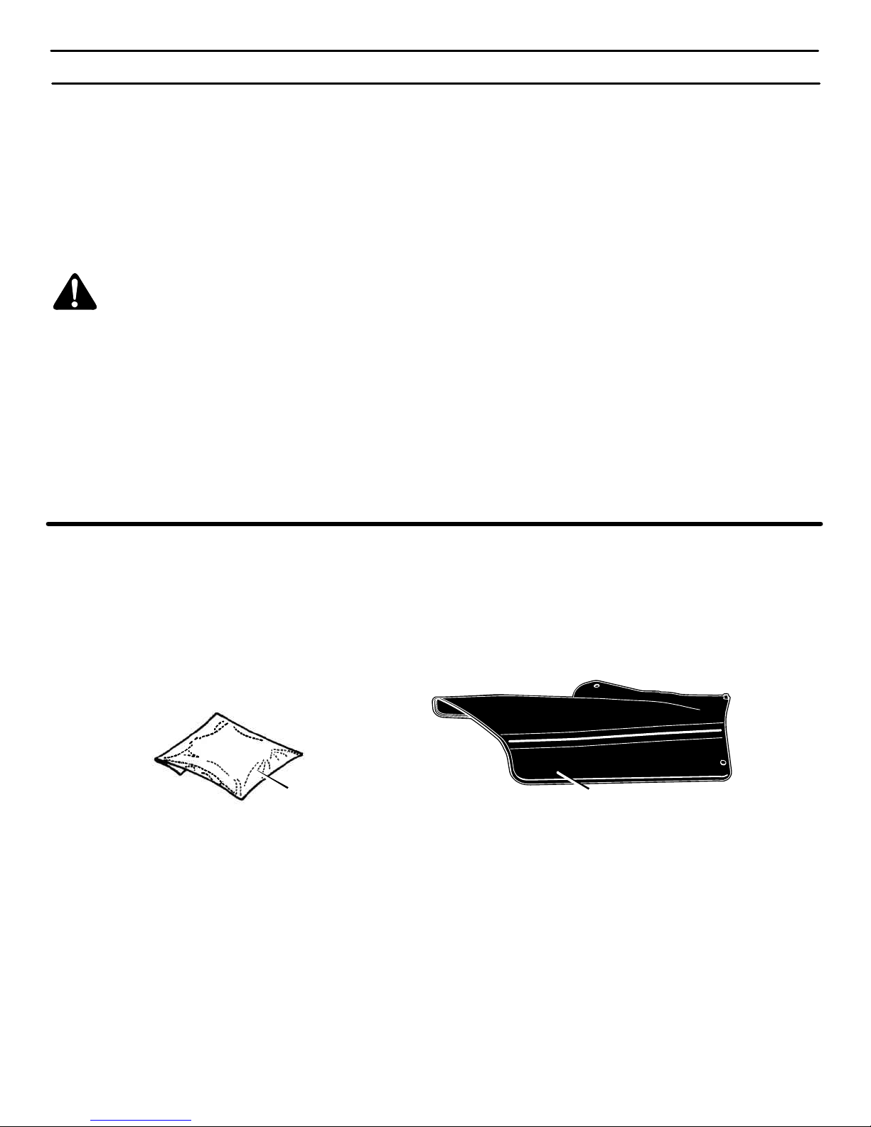
LOOSE PARTS − CONTENTS
The fasteners and other loose parts are shown below. The fasteners are shown full size. The quantity is shown in brackets ( ).
Literature Kit
Side Discharge Attachment
400150
Page 8
PREPARATION
8
MAINTENANCE FREE BATTERY
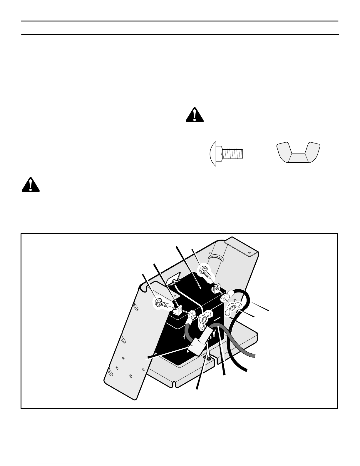
IMPORTANT: Before you attach the battery cables to the
battery, check the battery date. The battery date tells if the
battery must be charged.
1. Raise the seat support and secure in the UP position with the
seat support rod.
2. Check the top and the side of the battery for the location of the
battery date (Figure 1).
3. If the battery is put into service before the battery date, the
battery cables can be attached without charging the battery.
See “How To Install The Battery Cables”.
4. If the battery is put into service after the battery date, the
battery must be charged. See “How To Charge The
Maintenance Free Battery”.
HOW TO CHARGE
THE MAINTENANCE FREE BATTERY
WARNING: When you charge the battery, do not
smoke. Keep the battery away from any sparks. The
fumes from the battery acid can cause an explosion.
1. To disconnect the battery retainer from the battery tray, push
in on the lower end of the battery retainer.
2. Remove the battery from the right side of the unit.
3. Remove the protective cap from the battery terminal.
4. Use a 12 volt battery charger to charge the battery. Charge at
a rate of 6 amperes for one hour. If you do not have a battery
charger, have a Sears or other qualified service center charge
the battery.
5. Install the battery and secure with the battery retainer. Make
sure the positive (+) terminal is on the right side.
HOW TO INSTALL THE BATTERY CABLES
WARNING: To prevent sparks, fasten the red cable to
the positive (+) terminal before you connect the black
cable.
Use the fasteners shown below to install the battery cables. The
fasteners are shown at full size.
(B)
14x79
(A)
2x82
1. Remove the protective cap from the battery terminal.
2. Fasten the red cable and terminal cover to the positive (+)
terminal with the fasteners as shown (Figure 1).
3. Fasten the black cable to the negative (−) terminal with the
fasteners as shown.
B
A
Positive (+)
Terminal
Black Cable
Battery Clamp
A
Battery
Figure 1
Red Cable
Terminal
Cover
400150
Page 9
PREPARATION
9
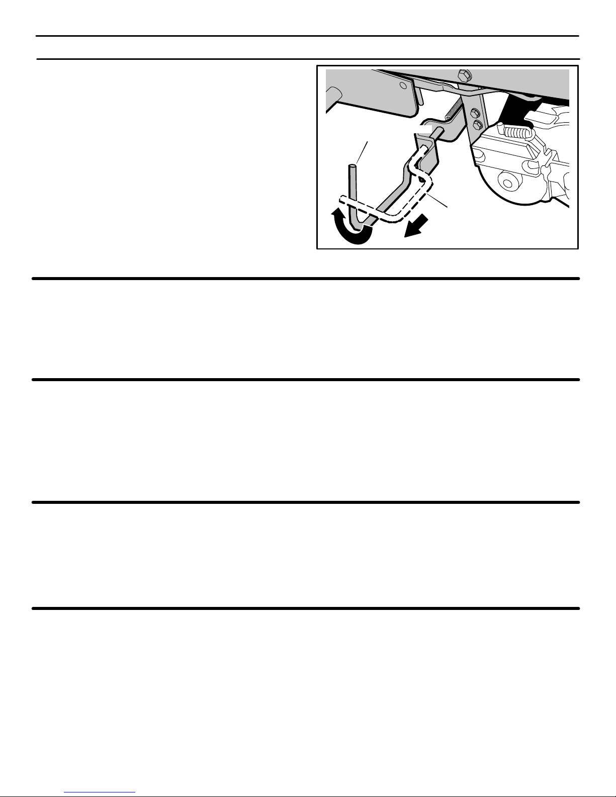
HOW TO ENGAGE THE TRANSMISSION
To allow the unit to be pushed, the unit was shipped with the
automatic drive disconnect in the PUSH POSITION. Before
operating, the automatic drive disconnect must be set in the
DRIVE POSITION. (Figure 2)
1. The engine must be off.
2. The automatic drive disconnect is located under the left side
of the seat deck next to the hydrostatic transaxle.
3. To engage the transmission, unlatch the automatic drive dis-
connect. The transmission is now connected and ready to op-
erate.
4. To release the transmission and push the unit, pull and twist the
automatic drive disconnect. Latch the automatic drive disconnect in the PUSH position (Figure 2). The transmission is
now released and the unit can be pushed.
NOTE: In cold weather, the heavy viscosity oil in the
transmission will make the unit difficult to push.
Figure 2
Automatic Drive Disconnect
DRIVE POSITION
Automatic Drive Disconnect
PUSH POSITION
HOW TO PREPARE THE ENGINE
NOTE: The engine was shipped from the factory filled with oil.
Check the level of the oil (see “Check The Oil” in the Operation
section). Add oil as needed.
NOTE: The operation of a new engine will sometimes result in
a slight amount of smoke. This smoke is caused by paint or oil
on or around the muffler. This is normal and only expected
during initial operation.
Before you use the unit, read the information on safety, operation,
maintenance, and storage.
CHECK THE TIRES
NOTE: The tires were over inflated for shipment. The correct air
pressure is shown on the side of the tire.
Check the air pressure in the tires. Tires with too much air pressure
will cause the unit to ride rough. Also, the wrong air pressure will
keep the mower housing from cutting level. The correct air pressure
is shown on the side of the tire.
CHECK THE LEVEL OF THE MOWER HOUSING
Make sure the level of cut is still correct. After you mow a short
distance, look at the area that was cut. If the mower housing does
not cut level, see the instructions on “How To Level The Mower
Housing” in the Service And Adjustment section of this instruction
book.
IMPORTANT! BEFORE YOU START MOWING
- Check the engine oil.
- Fill the fuel tank with gasoline.
- Check the air pressure of the tires.
- Check the level of the mower housing.
- Make sure the battery cables are attached.
- Make sure the wire is attached to the spark plug.
400150
Page 10
OPERATION
10
Figure 3
Throttle Control
Lever
Attachment
Clutch
Clutch / Brake
Pedal
Lift Lever
Speed Control
Lever
Ignition Key Switch
The operation of any lawn mower can result in foreign objects thrown in the eyes, which can result in severe eye
damage. Always wear safety glasses or eye shields before starting your lawn mower and while mowing. We recommend standard safety glasses or a wide vision safety mask worn over the spectacles or standard safety glasses,
available at Sears Stores.
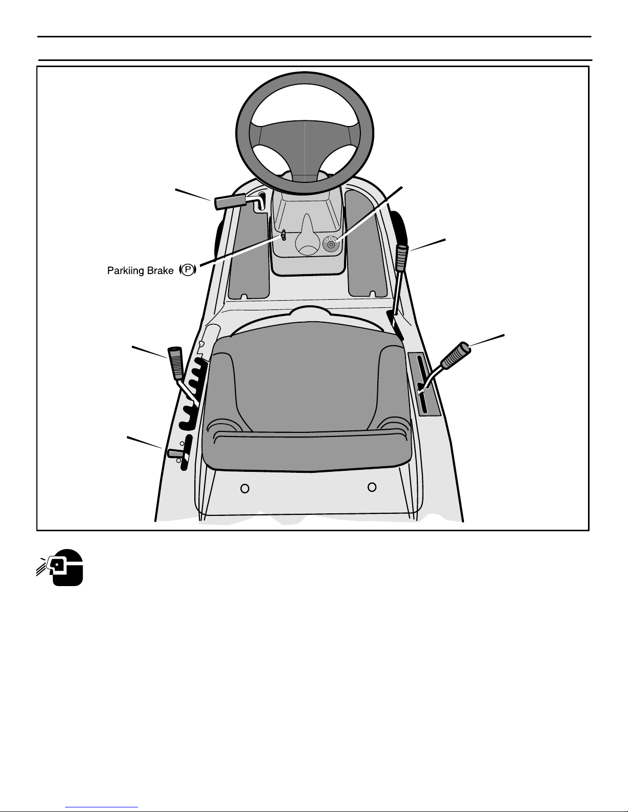
LOCATION OF CONTROLS
ATTACHMENT CLUTCH:
Use the attachment clutch to
start and stop the rotation of the blade(s) and to operate a snow
thrower attachment.
CLUTCH / BRAKE PEDAL: The pedal has two functions.
The first function is a clutch. The second function is a brake. Use the
brake pedal to quickly stop the forward or reverse motion of the unit.
IGNITION KEY SWITCH: Use the ignition key switch to
start and stop the engine. When you start the engine and release the
ignition key, the ignition key switch will automatically default to the
recommended RUN−MOW position for normal mowing.
SPEED CONTROL LEVER: Use the speed control lever
to change the speed and the direction of the unit.
LIFT LEVER: Use the lift lever to change the height of cut.
PARKING BRAKE LEVER: Use the parking brake lever
to engage the brake when you leave the unit.
THROTTLE CONTROL LEVER: Use the throttle control
lever to increase or decrease the speed of the engine.
400150
Page 11
OPERATION
11
ATTACHMENTS
This unit can use many different attachments. See the attachment
page in this book. This unit can pull attachments like a lawn
sweeper, a lawn aerator, a hopper spreader, or a small trailer. This
unit cannot use attachments that engage the ground like a plow, a
disk harrow, or a cultivator.
For all pull−behind attachments or trailers, the maximum gross
weight is 200 pounds. Gross weight is the weight of the attachment
or trailer and any load that might be on or in it.
Do not operate on a slope that is greater than 10 degrees when
using a pull−behind attachment or trailer. We have included a slope
guide in this book to help you determine the slope on which you will
be operating your unit. Never allow someone to stand or ride on or
in an attachment or trailer.
ELECTRICAL SAFETY SYSTEM
The electrical system has three primary components, an Operator
Presence System and a Select Reverset System, and a Run-Mow
System.
Operator Presence System (Seat)
The seat has an Operator Presence System to shut off the engine
when the operator leaves the seat. This system is not intended for
regular use in stopping the engine or the blade(s). Before leaving the
seat, move the blade rotation control to the DISENGAGE position,
shift to neutral, set the parking brake and stop the engine.
Select Reverset System
The Select Reverset system will allow the mower blade(s) to
continue to rotate when traveling in reverse. See “How To Operate
The Ignition Key Switch” and “How To Start The Engine” for further
details.
How To Check The Safety Interlock Switches
To check the function of the safety interlock switches, follow the
steps below.
1. Check the attachment clutch switch. Sit in the seat. Depress
the clutch/brake pedal. Move the attachment clutch to the ENGAGE position. Turn the ignition switch to the START position.
The engine should not start. If the engine starts, the switch is
defective and must be replaced.
2. Check the clutch/brake switch. Sit in the seat. Move the at-
tachment clutch to the DISENGAGE position. DO NOT depress the clutch/brake pedal. Turn the ignition switch to the
START position. The engine should not start. If the engine
starts, the switch is defective and must be replaced.
3. Check the Operator Presence System switch. DO NOT sit
in the seat. Depress the clutch/brake pedal. Move the attach-
ment clutch to the DISENGAGE position. Turn the ignition
switch to the START position. The engine should not start. If
the engine starts, the switch is defective and must be replaced.
4. Check the Select Reverset switch. Sit in the seat. Depress
the clutch/brake pedal. Move the attachment clutch to the DISENGAGE position. Start the engine and move the drive control
to the reverse (R) position. With the engine running, move the
attachment clutch to the ENGAGE position. The engine should
stop running. If the engine continues to run, the Select Re-
verset switch is defective and must be replaced.
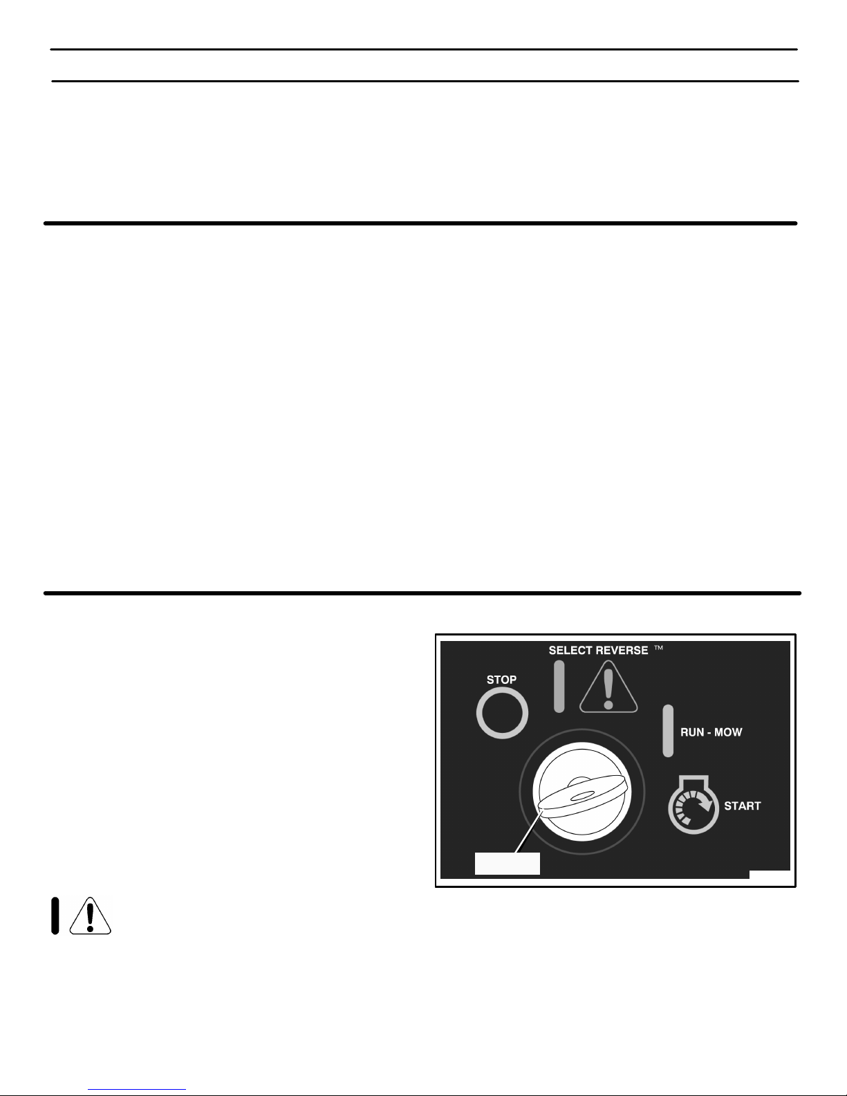
HOW TO OPERATE THE IGNITION KEY SWITCH
Use the ignition key switch to start and stop the engine. When you
start the engine and release the ignition key, the ignition key switch
will automatically default to the recommended RUN−MOW position
for normal mowing.
START − Use this position to start the engine.
RUN-MOW − When you start the engine and release the ignition
key, the ignition key switch will automatically default to the
recommended RUN-MOW position for normal mowing. In the
RUN-MOW position, the system will stop the engine and the
blade(s) when the speed control pedal/shift lever is put in the
reverse position.
SELECT REVERSEt − The optional Select Reverset
position will allow the mower blade(s) to continue to rotate when
traveling in reverse. Always go back to the recommended
RUN-MOW position for normal mowing when operation in Select
Reverset is not absolutely necessary. NEVER use the Select
Reverset option if children are on or near the property.
WARNING: Operators are strongly discouraged
from using this option unless the operator de-
cides it is absolutely necessary and that safe precautions are taken. Never use this Select Reverset option if
children are on or near the property. Always look down and
behind before and while backing. After using the Select Reverset position, move the ignition key back to the RUN-MOW
position.
STOP − Use this position to stop the engine.
Figure 4
Ignition
Key Switch
400150
Page 12
OPERATION
12
HOW TO STOP THE UNIT
1. Completely push the clutch/brake pedal forward to stop the
unit. Keep your foot on the pedal.
2. Move the attachment clutch to the DISENGAGE position.
3. Move the speed control lever to the NEUTRAL position.
4. Set the parking brake.
WARNING: Make sure the parking brake will hold the
unit.
5. Move the throttle control to the SLOW position.
6. To stop the engine, turn the ignition key to the STOP
posi-
tion. Remove the key.
CAUTION: To stop the engine, do not move the choke control
to CHOKE position. Backfire or engine damage can occur.
HOW TO SET THE PARKING BRAKE
1. Completely push the clutch/brake pedal forward.
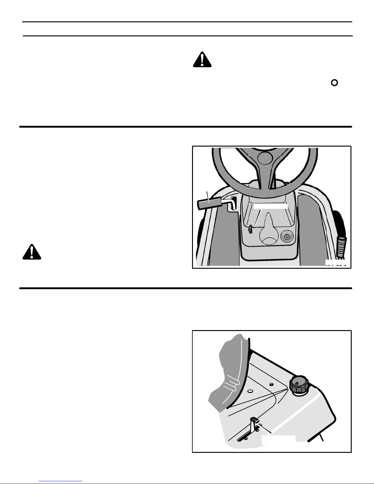
2. Lift the parking brake lever (Figure 5).
3. Remove your foot from the clutch/brake pedal and then release
the parking brake lever. Make sure the parking brake will hold
the unit.
4. To release the parking brake, completely push the clutch/
brake pedal forward. The parking brake will automatically release.
WARNING: Before you leave the operator’s position,
move the shift lever to the neutral (N) position. Set the
parking brake. Move the attachment clutch to the
DISENGAGE position. Stop the engine and remove
the ignition key.
Figure 5
Parking Brake
Clutch/Brake
Pedal
HOW TO USE
THE THROTTLE / CHOKE CONTROL
CAUTION: Always operate the engine with the throttle control
in the FAST position. If the engine runs for several minutes at
slower than the FAST position, the engine and transmission
will overheat and can be damaged.
Use the throttle/choke control to choke the engine for cold starts
and increase or decrease the speed of the engine (see Figure 6).
1. Move the throttle/choke control completely forward to the
CHOKE position to start a cold engine.
2. The FAST position is marked with a detent. For normal operation and when using a grass bagger, move the throttle control
to the FAST position. For maximum charging of the battery and
for a cooler running engine, operate the engine in the FAST
position.
3. For transport and to tow pull behind attachments, control the
ground speed with the speed control pedal.
4. The engine governor is set at the factory for maximum performance. Do not adjust the governor to increase the speed of the
engine.
Throttle
Control
Figure 6
400150
Page 13
OPERATION
13
HOW TO USE THE ATTACHMENT CLUTCH
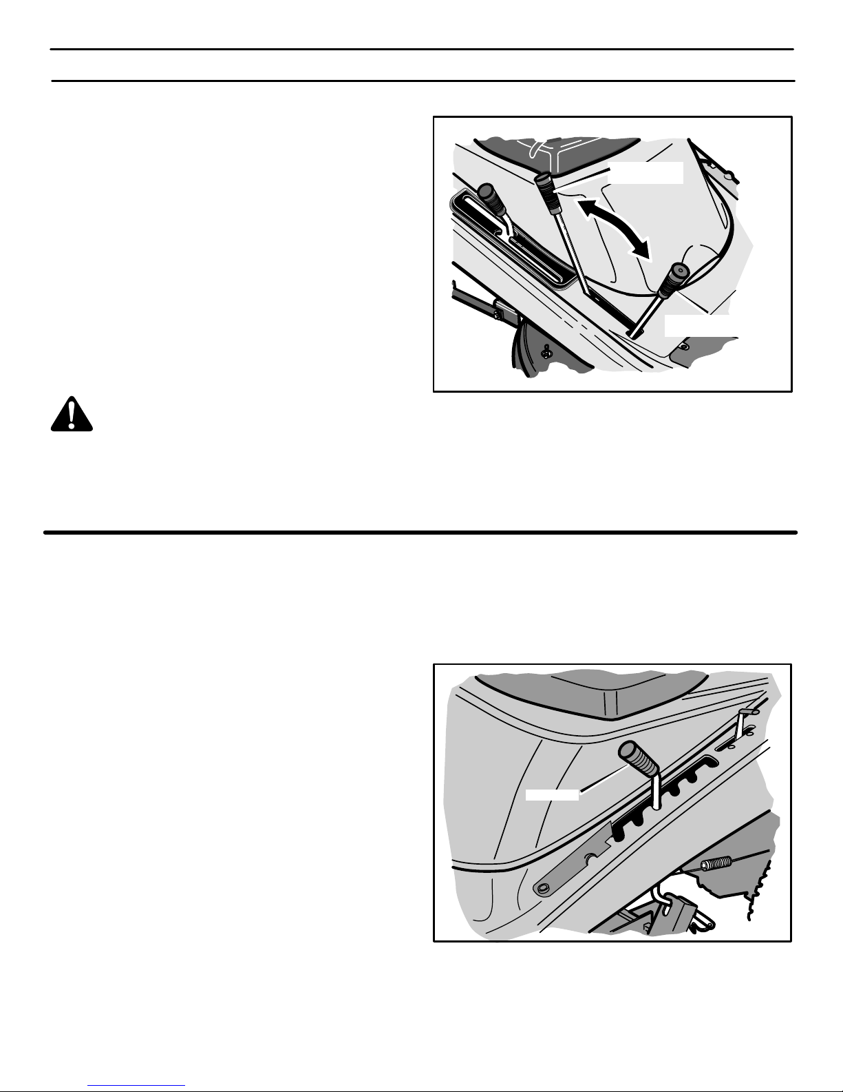
Use the attachment clutch to engage the blade (Figure 7).
1. Before you start the engine, make sure the attachment clutch
is in the DISENGAGE position.
2. To rotate the blade, move the attachment clutch forward to
lock the blade in the ENGAGE position.
Note: If the engine stops when you engage the blade(s),
the transmission is in reverse.
3. To stop the blade, move the attachment clutch to the DISENGAGE position. Before you leave the operator’s position,
make sure the blade has stopped rotating.
4. Before you ride the unit across a sidewalk or a road, move the
attachment clutch to the DISENGAGE position.
5. Before operating in reverse, move the blade rotation control to
the DISENGAGED position. If the blade rotation control is not
in the DISENGAGED position, the engine will stop when the
speed control pedal/shift lever is moved to REVERSE position.
WARNING: Always keep your hands and feet away
from the blade, deflector opening, and the mower
housing when the engine runs.
Attachment Clutch
Engage Position
Disengage
Position
Figure 7
HOW TO CHANGE THE CUTTING HEIGHT
To change the cutting height, raise or lower the lift lever as follows.
1. Move the lift lever forward to lower the mower housing and
back to raise the mower housing (Figure 8).
2. When you ride on a sidewalk or road, move the lift lever to the
highest position and move the attachment clutch to the
DISENGAGE position.
Lift Lever
Figure 8
400150
Page 14
OPERATION
14
HOW TO DISCONNECT THE TRANSMISSION
To push the unit, use the automatic drive disconnect to release
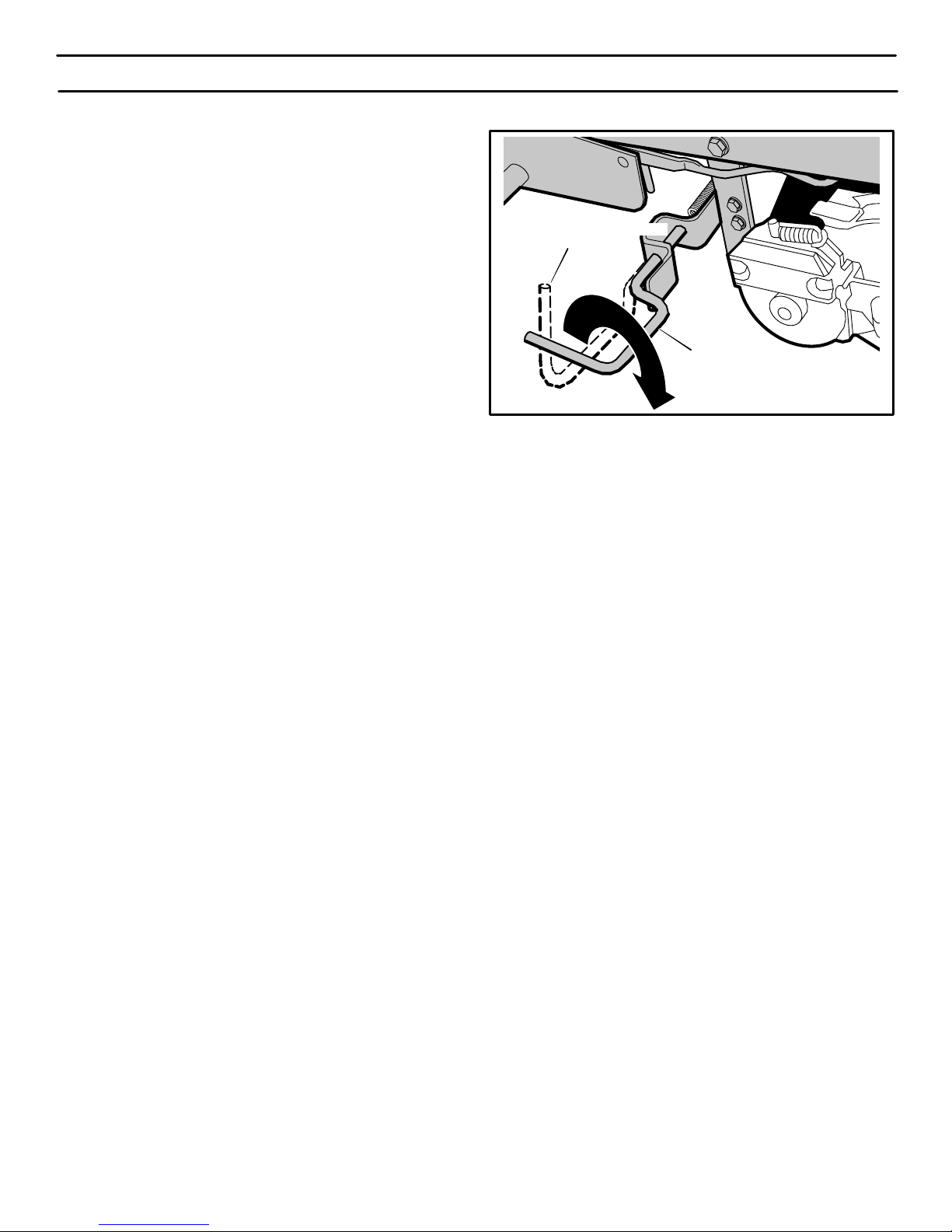
the transmission. (Figure 9)
1. The engine must be off.
2. The automatic drive disconnect is located under the left side
of the seat deck next to the hydrostatic transaxle.
3. To release the transmission and push the unit, pull and twist the
automatic drive disconnect.. Latch the automatic drive disconnect in the PUSH position (Figure 9). The transmission is
now released and the unit can be pushed.
NOTE: In cold weather, the heavy viscosity oil in the
transmission will make the unit difficult to push.
4. To engage the transmission, unlatch the automatic drive disconnect. The transmission is now connected and ready to op-
erate.
Figure 9
Automatic Drive Disconnect
DRIVE POSITION
Automatic Drive Disconnect
PUSH POSITION
400150
Page 15
OPERATION
15
HOW TO USE THE SPEED CONTROL LEVER
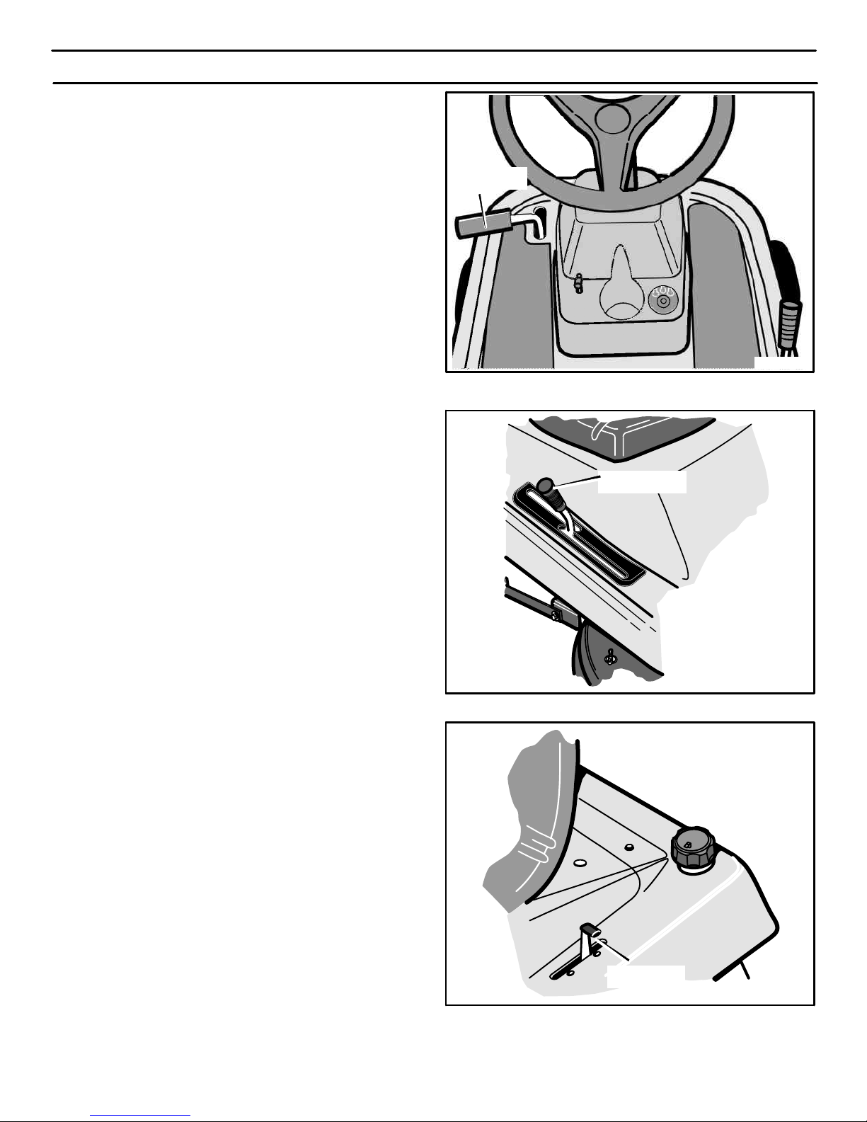
The Hydrostatic Drive is very easy to operate. The drive system has
a a clutch/brake pedal on the left side (see Figure 10) and a speed
control lever on the right side (see Figure 11).
The speed and direction of travel is controlled by the speed control
lever (see Figure 11). Use the speed control lever to select either
forward or reverse.
HOW TO DRIVE FORWARD
1. The automatic drive disconnect must be in the DRIVE
position (Figure 9).
2. Completely push the clutch/brake pedal forward to stop the unit
(see Figure 10). Keep your foot on the pedal.
3. Move the speed control lever to NEUTRAL position (see
Figure 11).
4. Slowly release your foot from the clutch/brake pedal (see
Figure 10). Do not keep your foot on the clutch/brake pedal.
5. Move the throttle control to the FAST position (see Figure 12).
6. Slowly push the speed control lever forward to the desired
speed (see Figure 10). To reduce forward speed, slowly pull the
speed control lever to the desired speed.
HOW TO CHANGE DIRECTIONS / DRIVE IN REVERSE
1. Always disengage blades and look down and behind before
and while backing up.
2. Move the speed control lever to the NEUTRAL position (see
Figure 11).
3. To go backward, move the speed control lever to the REVERSE
position.
Figure 10
Clutch/Brake
Pedal
Speed Control
Lever
Figure 11
Throttle
Control Lever
Figure 12
400150
Page 16

OPERATION
16
SPEED CONTROL LEVER POSITIONS
The forward speed is controlled by the position of the speed control
lever. The following chart provides functions along with the
positions of the speed control lever. Always operate the engine
with the throttle control in the FAST position.
FUNCTION
SPEED
CONTROL
LEVER
POSITION
THROTTLE
Trimming
Steep Hills
1/3
FAST
CHOKE
FAST
SLOW
THROTTLE
Bagging Grass 1/3 to 1/2
Normal Mowing 1/2 to 2/3
Easy Mowing 1/2 to 3/4
Transport FULL
Pull Behind
Attachments
1/3 to 1/2
HOW TO TRANSPORT THE UNIT
To transport the unit, follow the steps below.
1. Move the attachment clutch to the DISENGAGE position.
2. Raise the lift lever to the highest position.
3. Move the throttle control to the FAST position (see Figure 14).
4. To go faster, move the speed control lever to a faster speed
(see Figure 13).
Speed Control
Lever
Figure 13
Throttle
Control Lever
Figure 14
400150
Page 17
OPERATION
17
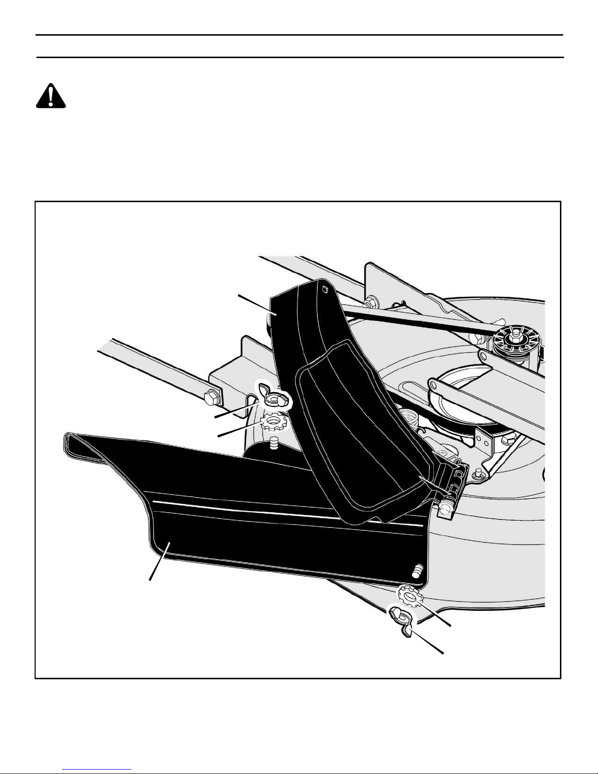
HOW TO INSTALL THE SIDE DISCHARGE ATTACHMENT
WARNING: To prevent the engine from starting, disconnect the wire from the spark plug. Make sure the
attachment clutch is in the DISENGAGE position.
The mulcher cover lets you mulch the grass for a clean, fine cut.
To discharge the grass out the side, install the side discharge
attachment as follows.
1. Remove the fasteners that secure the mulcher cover (see
Figure 15).
2. Lift the mulcher cover. Mount the side discharge attachment
onto the same bolts that secured the mulcher cover.
3. Secure the side discharge attachment with the fasteners.
4. To mulch, remove the side discharge attachment and mount
the mulcher cover to the mower housing with the fasteners.
Figure 15
Side Discharge Attachment
Mulcher Cover
Wingnut
Wingnut
Washer
Washer
400150
Page 18
OPERATION
18
BEFORE STARTING THE ENGINE
CHECK THE OIL
NOTE: The engine was shipped from the factory filled with oil
rated 30. Check the level of the oil. Add oil as needed.
1. Make sure the unit is level.
NOTE: Do not check the level of the oil while the engine
runs.
2. Clean the area around the dipstick. Remove the dipstick. Wipe
the oil from the dipstick.
3. Insert the dipstick into the oil fill tube. Turn the dipstick clockwise until it is tight. Remove the dipstick. Check the oil level on
the dipstick. The oil level must reach the FULL mark on the
dipstick.
4. If necessary, add oil until the oil reaches the FULL mark on the
dipstick. The quantity of oil needed from ADD to FULL is shown
on the dipstick. Do not add too much oil.
GASOLINE REQUIREMENTS
All gasoline is not the same. If a starting or performance problem is
encountered after new gasoline has been used, try another service
station or change brands.
Type of gasoline to use
Always use gasoline that meets these requirements:
¯ Clean, fresh, unleaded gasoline.
¯ A minimun of 87 octane/87 AKI (91 RON). At altitudes over
5,000 feet, see “High-altitude use”.
¯ Gasoline with up to 10% ethanol (gasohol) or up to 15%
MTBE (methyl tertiary butyl ether), is acceptable.
¯ Use of any gasoline other than those approved above will
void the engine warranty. Some areas require that fuel
pumps be marked if the gasoline contains alcohols or ethers.
If you are not sure if your gasoline contains alcohol or ethers
that are different than those approved above, then check with
the service station operator.
¯ Do not modify the engine fuel system or carburetor to run on
alternative fuels.
¯ Never mix oil with gasoline.
This engine is designed to operate on gasoline. The emission
control system for this engine is EM (Engine Modifications).
ADD GASOLINE
WARNING: Always use a safety gasoline container.
Do not smoke when adding gasoline to the fuel tank.
Do not add gasoline when you are inside an enclosure. Before you add gasoline, stop the engine and
let the engine cool for several minutes.
1. Stop the engine. Before you remove gas cap, let the engine
cool at least 2 minutes.
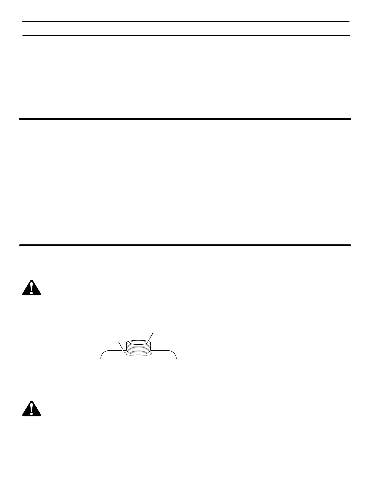
2. Remove the gas cap. Fill
the fuel tank to approximately 1-1/2 inches below
top of neck to allow for fuel
expansion. Be careful, do
not overfill.
3. Before starting the engine, replace the gas cap.
WARNING: Gasoline is flammable. Always use caution when handling or storing gasoline.
S Turn engine off and let engine cool at least two minutes
before removing the gas cap.
S Do not fill fuel tank while engine is running, when it is hot,
or when equipment is in an enclosed area.
S Keep away from open flame or an electrical spark and do
not smoke while filling the fuel tank.
S Never fill the tank completely. Fill the tank to approxi-
mately 1-1/2” below the top of the tank opening to provide
space for expansion of fuel.
S Always fill fuel tank outdoors and use a funnel or spout to
prevent spilling.
S Make sure to wipe up any spilled fuel before stating the
engine.
S Store gasoline in a clean, approved container and keep
the cap in place on the container.
CAUTION: Alcohol blended fuels (called gasohol or ethanol)
can attract moisture which leads to separation and formation
of acids during storage. Acidic gas can damage the fuel system
of an engine while in storage.
To prevent engine problems with the fuel system, empty the fuel
system before storage of 30 days or longer as follows.
1. Drain the fuel tank.
2. Start the engine. Let the engine run until the fuel lines and the
carburetor are empty.
3. After storage, make sure you use fresh fuel. See the storage
instructions for additional information.
4. Never use engine cleaner or carburetor cleaner in the fuel tank
or permanent damage can occur.
Fuel Tank
Full
400150
Page 19
OPERATION
19
CARBURETOR
The factory settings for the carburetor are for most conditions. If the
engine is operated under the following conditions, the carburetor
may require an adjustment. For service, contact a Sears or other
qualified service center.
1. The engine has a loss of power or does not run smooth.
2. A change from summer to winter operation.
3. A 40 degree change in the operation temperature. The carburetor was adjusted at 80 degrees at the factory.
4. The engine is operated above 4,000 feet above sea level.
HOW TO START THE ENGINE
WARNING: The electrical system has two primary
components, an operator presence system and a
Select Reverset system. The operator presence
system determines if the operator is sitting on the
seat. This system will stop the engine when the
operator leaves the seat. The Select Reverset
system gives the operator the ability to temporarily
mow in reverse if he decides such operation is
absolutely necessary and safe operating precautions
are taken. For your protection, always make sure
these systems operate correctly.
NOTE: The engine will not start unless you depress the
clutch/brake pedal or engage the parking brake and move the
attachment clutch to the DISENGAGE position.
1. Make sure the spark plug wire is connected to the spark plug.
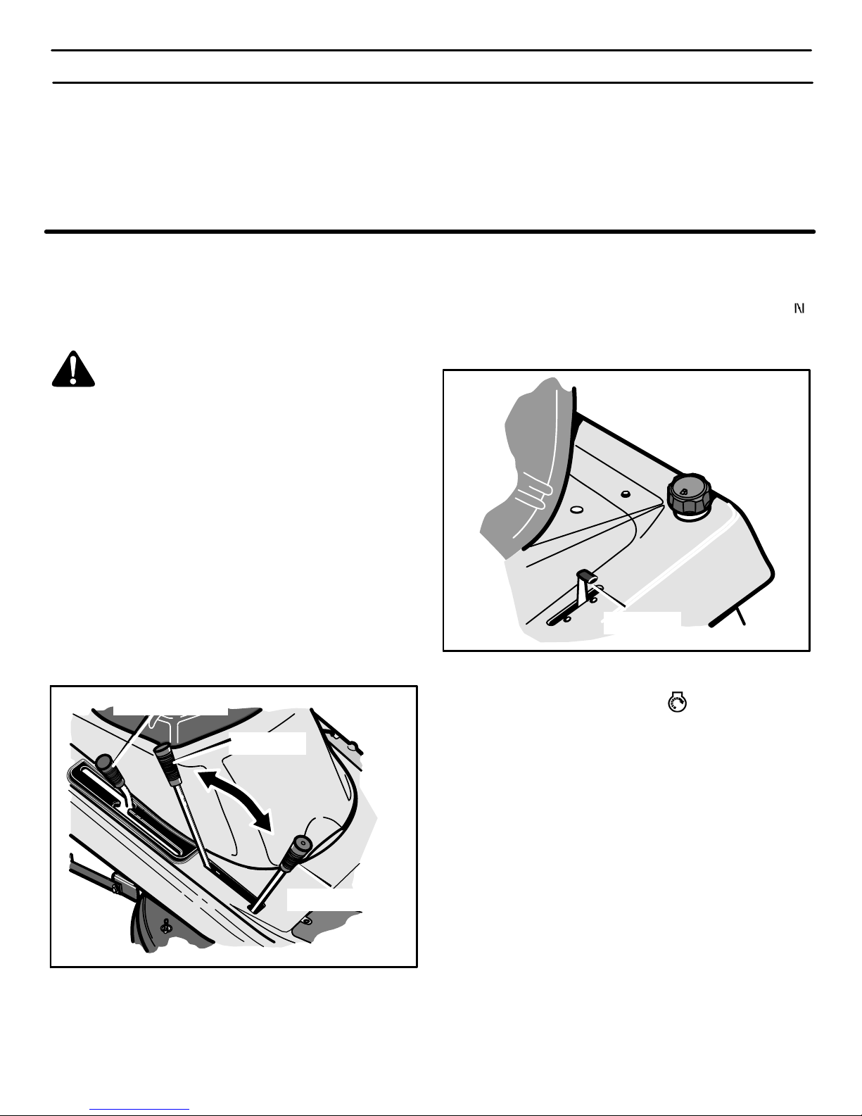
2. Move the speed control lever to the neutral (N) position (see
Figure 16).
3. Make sure the attachment clutch is in the DISENGAGE position. If the blade rotation control is not in the DISENGAGE position, the engine will not start.
Attachment Clutch
Engage Position
Disengage
Position
Figure 16
Speed Control Lever
4. Move the throttle control completely forward to the CHOKE
or FAST position (see Figure 17).
Throttle
Control Lever
Figure 17
5. Turn the ignition key to the START position. Release the
key when the engine starts. The ignition key switch will automatically default to the recommended RUN−MOW position for
normal mowing. See “How To Operate The Ignition Key Switch”
in the Operation Section.
NOTE: If the engine does not start after four or five tries,
move the throttle control to the FAST position. Again try to
start the engine. If the engine will not start, see the
TROUBLESHOOTING CHART.
6. Slowly move the throttle control to the SLOW position.
7. Let a cold engine run for several minutes. Begin work when the
engine is warm. To start a hot engine, move the throttle control
to a position between FAST and SLOW.
400150
Page 20
OPERATION
20
HOW TO OPERATE WITH THE MOWER HOUSING
WARNING: The mulch cover is a safety device. Do not
remove the mulch cover. The side discharge attachment forces the discharged material toward the
ground. Always keep the side discharge attachment
in the down position. If the side discharge attachment
is damaged, replace the with an original equipment
part from a Sears Service Center.
IMPORTANT: When you operate with the mower housing,
always operate with the throttle control in the FAST position.
1. Push the clutch/brake pedal completely forward.
2. Start the engine.
3. Put the speed control lever in the NEUTRAL position.
4. Slowly release the clutch/brake pedal.
5. Move the lift lever to a height of cut position. In high or thick
grass, cut the grass in the highest position first and then lower
the mower housing to a lower position.
CAUTION: Do not operate with the mower housing in the
LEVEL ADJUSTMENT position. If you operate in the
LEVEL ADJUSTMENT position, the mower housing and
blades can be damaged.
6. Move the throttle control to the SLOW position.
7. Move the attachment clutch to the ENGAGE position.
8. Move the speed control lever forward.
NOTE: When you mow in heavy grass or mow with a
bagger, operate at a slow forward speed.
9. Move the throttle control to the FAST position. If you need to go
faster or slower, move the speed control lever forward or backward.
10. Make sure the level of cut is still correct. After you mow a short
distance, look at the area that was cut. If the mower housing
does not cut level, see the instructions on “How To Level The
Mower Housing” in the Service And Adjustment section.
WARNING: For better control of the unit, always
select a safe speed.
HOW TO OPERATE THE UNIT ON HILLS
WARNING: Do not ride up or down slopes that are too
steep to back straight up. Never ride the unit across
a slope. See the “Slope Guide” in the back of this
book for information on how to check slopes.
1. Before you ride up or down a hill, move the speed control lever
to a slow speed.
2. Do not stop or change speed settings on a hill. If you must stop,
quickly push the clutch/brake pedal forward and set the parking
brake.
3. To start again, make sure the speed control
lever is in a slow
speed. Move the throttle control to the SLOW position. Slowly
release the pedal.
4. If you must stop or start on a hill, always have enough space
for the unit to roll when you release the brake and engage the
clutch.
5. Be very careful when you change directions on a hill. When on
a slope or in a turn on a hill, move the throttle control to the
SLOW position to help prevent an accident.
400150
Page 21
OPERATION
21
OPERATING TIPS
1. Check the attachment clutch for correct adjustment. For the
blade(s) to disengage correctly, the adjustment must be correct.
2. Before you use the unit, check the oil in the engine and add oil
if necessary.
3. If the engine will not start, first make sure the wire is attached
to the spark plug.
4. Make sure all the belts are inside all the belt guides. See the instructions on how to remove and install the motion drive and
mower drive belts.
5. Before you make an inspection, adjustment (except for the carburetor) or repair, make sure the wire from the spark plug is disconnected.
6. Make sure the seat switch wire is connected. If the wire is not
connected, the engine will not start.
7. For longer life of the battery, charge the battery every three
months.
8. Use the shift lever to change the ground speed, not the throttle
control.
9. Belt noise can occur when the blade or clutch is engaged. This
noise is normal and does not affect the operation of the unit.
10. To move forward, always release the clutch/brake pedal slowly.
MOWING AND BAGGING TIPS
1. For a lawn to look better, check the cutting level of the mower
housing. See “How To Level The Mower Housing” in the Service And Adjustment section.
2. For the mower housing to cut level, make sure the tires have
the correct amount of air pressure (PSI) and use slow ground
speeds when turning.
3. Every time you use the unit, check the blade. If the blade is bent
or damaged, immediately replace the blade. Also, make sure
the nut for the blade is tight.
4. Keep the blade(s) sharpened. A worn blade(s) will cause the
ends of the grass to turn brown.
5. Do not cut or bag grass that is wet. Wet grass will not discharge
correctly. Let the grass dry before cutting.
6. Use the left side of the mower housing to trim near an object.
7. Discharge the cut grass onto the mowed area. The result is a
more even discharge of cut grass.
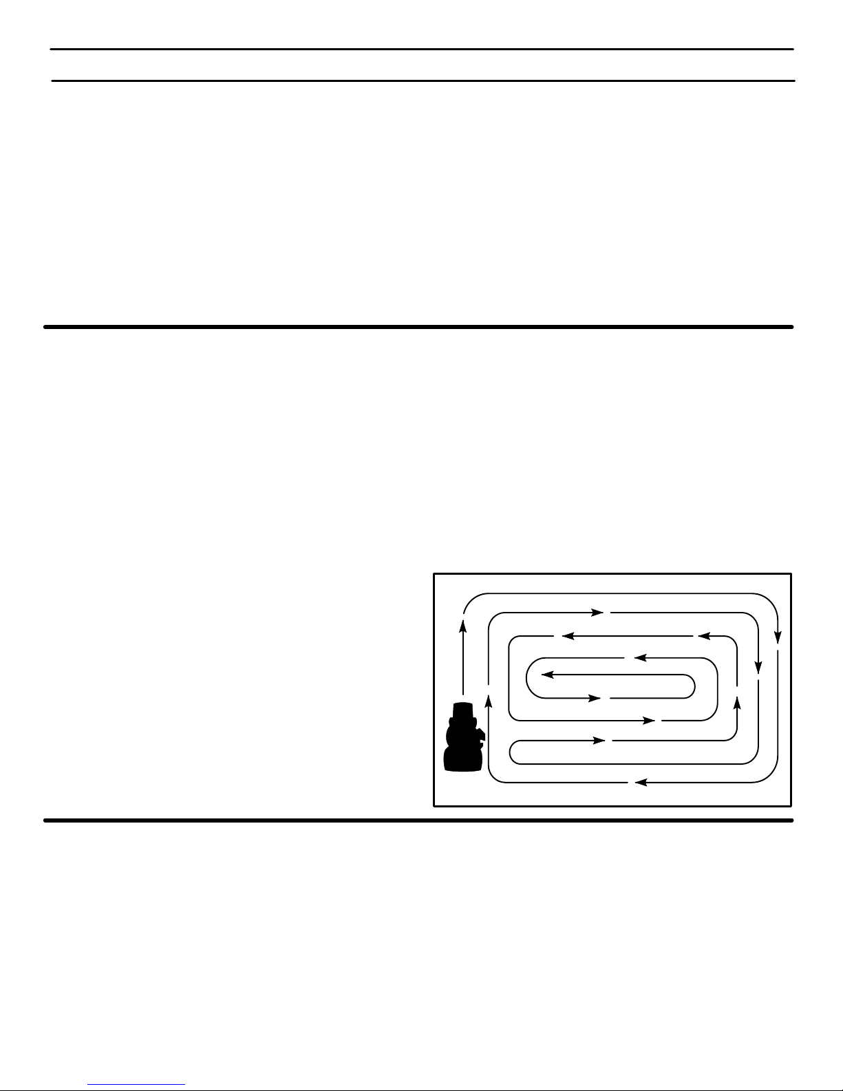
8. When you mow large areas, start by turning to the right so that
the cut grass will discharge away from shrubs, fences, driveways, etc. After one or two rounds, mow in the opposite direction making left turns until finished (Figure 18).
9. Use a mowing pattern that eliminates reverse travel as much
as possible.
10. If the grass is very high, cut two times to decrease the load on
the engine. First cut with the mower housing in the highest position and then lower the mower housing for the second cut.
11. For better engine performance and an even discharge of the
cut grass, always operate the engine with the throttle in FAST
position.
12. When you use a bagger, operate the engine with the throttle in
FAST position and the speed control lever in a slow forward
speed.
13. For better cutting performance and a quality cut, mow in a slow
forward speed.
14. After each use, clean the bottom and top of the mower housing
for better performance. Also, a clean mower housing will help
prevent a fire.
Figure 18
MULCHING TIPS
When you use a mulcher attachment, the grass is cut into very small
pieces. These small pieces will quickly break down. Because the
nutrients are returned to the soil, the lawn will need less fertilizer. Too
correctly mulch the grass, follow the steps below.
1. Set the throttle in the FAST position. Operate the mower at a
slower ground speed. If ground speed is too fast, the grass will
not have an even cut.
2. Keep a sharp edge on the blade. A blade that is not sharp will
cause the ends of the grass to become brown.
3. Make sure the grass is dry. Wet grass is difficult to cut.
4. Set the height of the mower housing so that only the top third
of the grass is cut. If the grass is too high, set the height of the
mower housing to the maximum height. Then, lower the mower
housing for the second cut. Also, instead of using the full width
of the mower housing, mulch at half the width.
5. Clean the bottom of the mower housing. Grass and other debris
can keep the mower from working correctly.
6. If the grass grows fast, mulch more often.
7. If an area needs improvement, mulch a second time.
400150
Page 22
MAINTENANCE
22
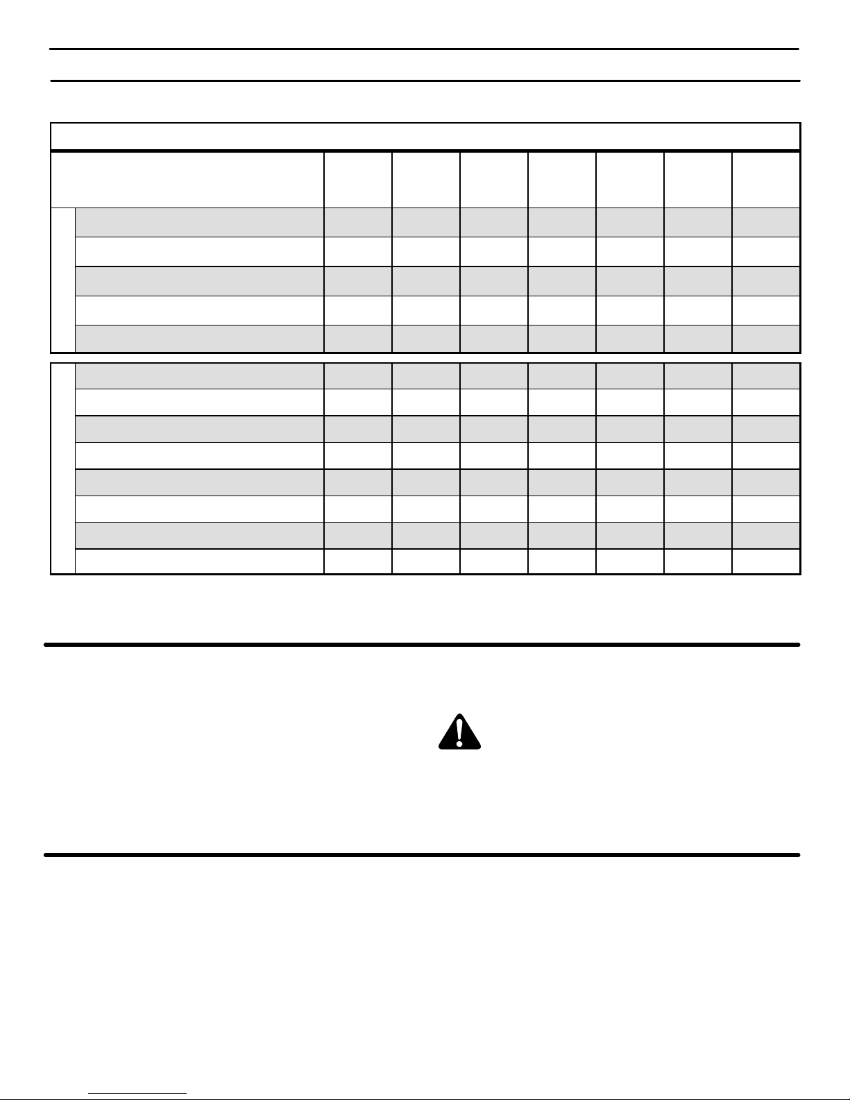
MAINTENANCE TABLE
PROCEDURE
EACH
USE
FIRST
2
HOURS
EVERY
8
HOURS
EVERY
25
HOURS
EVERY
50
HOURS
EVERY
100
HOURS
BEFORE
STORAGE
M
O
W
E
R
Tires, Check
√
Blade, Inspect and Sharpen
√
Battery, Check and Charge
√ √
Battery, Clean
√ √
Lubrication
√ √
E
N
G
I
N
E
Oil, Check
√ √
Oil, Change
√ √* √
Cooling System, Clean / Check
√** √
Muffler, Check
√ √
Pre-Cleaner Filter, Service
√
Air Cleaner Cartridge Filter, Service
√
Spark Plug, Check
√ √
Spark Plug, Replace
√
* Change oil every 25 hours when operating under heavy load or in high temperatures.
** Clean cooling system more often if operating under dusty conditions.
GENERAL RECOMMENDATIONS
1. The owner’s responsibility is to maintain this product. This will
extend the life of the product and is also necessary to maintain
warranty coverage.
2. Check the spark plug, drive brake, lubricate the unit, and clean
the air filter once a year.
3. Check the fasteners. Make sure all fasteners are tight.
4. Follow the Maintenance and the Service And Adjustment section to keep the unit in good operating condition.
WARNING: Before you make an inspection, adjustment, or repair to the unit, disconnect the wire to the
spark plug. Remove the wire from the spark plug to
prevent the engine from starting by accident.
Maintenance, replacement, or repair of the emission control devices
and systems may be performed by any Sears or other qualified
service dealer. Regular maintenance will improve the performance
and extend the life of the engine.
CHECK THE TIRES
Check the air pressure in the tires. Tires with too much air pressure
will cause the unit to ride rough. Also, the wrong air pressure will
keep the mower housing from cutting level. The correct air pressure
(PSI) is shown on the side of the tire.
400150
Page 23

MAINTENANCE
23
INSPECT BLADE
WARNING: Before you inspect or remove the blade,
disconnect the wire to the spark plug. If the blade
hits an object, stop the engine. Check the unit for
damage. The blade has sharp edges. When you
hold the blade, use gloves or cloth material to protect your hands.
If you keep the blade sharp and inspect the blade for damage,
the blade will cut better and be more safe to operate. Frequently
check the blade for excessive wear, cracks, or other damage.
Frequently check the nut that holds the blade. Keep the nut tight.
If the blade hits an object, stop the engine. Disconnect the wire to
the spark plug. See if the blade is bent or damaged. Check the
blade adapter for damage. Before you operate the unit, replace
damaged parts with original equipment parts. See a Sears
Service Center in your area. Every three years, have a qualified
service person inspect the blade or replace the old blade with an
original equipment part.
HOW TO REMOVE AND INSTALL THE BLADE
To Remove
1. Remove the mower housing. See the instructions on “How To
Remove The Mower Housing”.
2. As you loosen the nut, use a piece of wood to keep the blade
from rotating.
3. Remove the nut, washers, and blade (Figure 19).
Hi−Lift
Edge Up
Mandrel
Blade Adapter
Blade
Belleville Washer
Washer
Nut
Figure 19
4. Check the blade and the blade adapter according to the
instructions for “Inspect Blade”. Replace a badly worn or
damaged blade with an original equipment blade. See a
Sears Service Center in your area.
5. Clean the top and bottom of the mower housing. Remove all
the grass and debris.
To Install
1. Mount the blade and blade adapter on the mandrel
(Figure 19).
2. Mount the blade so that the hi-lift edges are up. If the blade
is upside down, the blade will not cut correctly and can
cause an accident.
3. Fasten the blade with the original washers and nut. Make
sure the outside rim of the Belleville washer is against the
blade (Figure 20).
WARNING: Always keep the nut tight that holds the
blade. A loose nut or blade can cause an accident.
4. Tighten the nut that holds the blade to a torque of 35 foot
pounds.
5. Install the mower housing. See “How To Install The Mower
Housing”.
Blade Adapter
Blade
Belleville Washer
(Outside rim must be
against the blade.)
Washer
Nut
Figure 20
HOW TO SHARPEN THE BLADE
WARNING: Vibration can be caused if the blade is
not correctly balanced or if the blade is damaged.
A blade that is damaged with cracks can break and
cause an accident.
Keep a sharp edge on the blade. A blade that is not sharp will
cause the tips of the grass to become brown.
1. Sharpen the blade two times a year or every 25 hours.
2. Remove the blade according to the instructions in “How To
Remove And Install The Blade”.
3. Clean the blade with a brush, soap and water. Check the
blade. Look for cracks, nicks, or other damage. Replace a
badly worn or damaged blade with an original equipment
blade. See a Sears Service Center in your area.
4. Sharpen the blade with a file (Figure 21). Make sure you
keep the original bevel angle.
5. Make sure the blade is balanced. Use a screwdriver and
hold the blade parallel to the ground (Figure 21). A blade
that is balanced will stay parallel to the ground. If the blade
is not balanced, the heavy end will rotate toward the ground.
Sharpen the heavy end until the blade is balanced.
6. A new blade will cut better than a badly worn blade. Every
three years, have a qualified service person inspect the
blade or replace the old blade with an original equipment
blade.
7. Assemble the blade according to the instructions “How To
Remove And Install The Blade”.
Ground
Blade is balanced
when parallel to the ground.
Screwdriver
Blade
File
Figure 21
400150
Page 24
MAINTENANCE
24
MAINTENANCE FREE BATTERY
HOW TO REMOVE THE BATTERY
To charge or clean the battery, remove the battery from the unit as
follows.
WARNING: To prevent sparks, disconnect the black
battery cable from the negative (−) terminal before you
disconnect the red cable.
WARNING: The battery contains sulfuric acid which is
harmful to the skin, eyes and clothing. If the acid gets
on the body or clothing, wash with water.
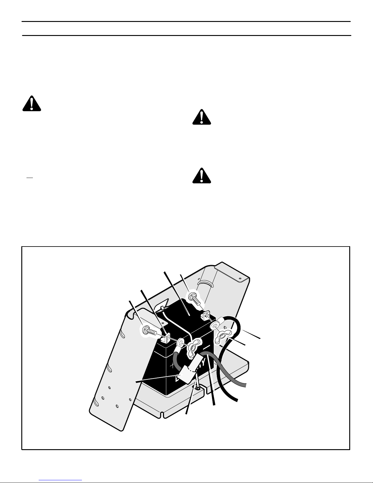
1. Disconnect the black cable from the negative (−) terminal
(Figure 22).
2. Disconnect the red cable from the positive (+) terminal.
3. To disconnect the battery retainer from the battery tray, push
in on the lower end of the battery retainer.
4.
Remove the battery from the right side of the unit.
HOW TO CLEAN THE BATTERY
1. Remove the battery.
2. Wash the battery with a solution of one gallon of water and four
tablespoons of baking soda (sodium bicarbonate). Make sure
the solution does not get into the battery cells.
3. Clean the terminals and the ends of the cables with a wire
brush.
4. Install the battery.
5. To prevent corrosion, apply grease to the battery terminals.
HOW TO CHARGE THE BATTERY
WARNING: When you charge the battery, do not
smoke. Keep the battery away from any sparks. The
fumes from the battery acid can cause an explosion.
1. Before you charge the battery, remove the battery.
2. To charge the battery, use a 12 volt battery charger. Charge at
a rate of 6 amperes for 1 hour.
3. Install the battery.
WARNING: To prevent sparks, fasten the red cable to
the positive (+) terminal before you connect the black
cable.
4. Fasten the red cable to the positive (+) terminal with the fasteners as shown.
5. Mount the battery boot onto the positive (+) terminal.
6. Fasten the black cable to the negative (−) terminal with the fasteners as shown.
B
A
Positive (+)
Terminal
Black Cable
Battery Clamp
A
Battery
Red Cable
Figure 22
Battery
Boot
400150
Page 25
MAINTENANCE
25
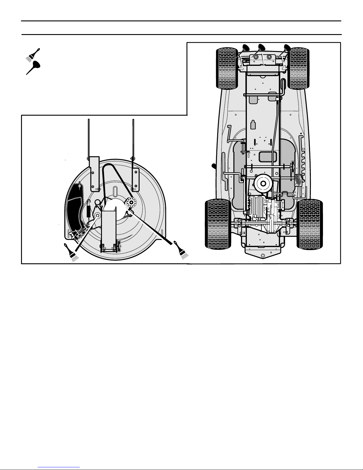
WHERE TO LUBRICATE
Lubricate the areas shown with engine oil.
Apply grease with a brush to the areas shown.
NOTE: Apply grease to the steering gear assembly.
CAUTION: If the unit is operated in dry areas that have sand,
use a dry graphite spray to lubricate the unit.
Figure 23
400150
Page 26

MAINTENANCE
26
ENGINE
HOW TO CHECK THE OIL
NOTE: Do not check the level of the oil while the engine runs.
1. Make sure the unit is level.
2. Clean the area around the dipstick (Figure 24). Remove the
dipstick. Wipe the oil from the dipstick.
3. Insert the dipstick into the oil fill tube. Turn the dipstick clockwise until it is tight. Remove the dipstick. Check the oil level on
the dipstick. The oil level must reach the FULL mark on the
dipstick.
4. If necessary, add oil until the oil reaches the FULL mark on the
dipstick. The quantity of oil needed from ADD to FULL is
shown on the dipstick. Do not add too much oil.
Figure 24
Dipstick
Air Screen
Dipstick
Oil Drain Plug
Air Screen
HOW TO CHANGE THE OIL
NOTE: Do not drain the oil from a cold engine. Before you drain
the oil, let the engine run for several minutes. Make sure you do
not get oil on the belts.
1. With the engine OFF but still warm, place the engine level and
disconnect the wire from the spark plug.
2. Remove the oil drain plug. Drain the oil completely from the
engine. Install and tighten the oil drain plug.
3. Only use a high quality detergent oil rated with API service
classification SG, SH, SJ or SL. Select the oil’s SAE viscosity
grade according to the expected operating temperature using
the temperature chart below:
NOTE: Synthetic oil meeting ILSAC GF-2, API certification mark and API service symbol (shown at left) with “SJ/
CF ENERGY CONSERVING” or higher, is an acceptable
oil at all temperatures. Use of synthetic oil does not alter
required oil change intervals.
Required SAE viscosity grades
Synthetic
**
*
* CAUTION: Air cooled engines run hotter than automotive
engines. The use of non-synthetic multi-viscosity oils (5W-30,
10W-30, etc.) in temperatures above 40_ F (4_ C) will result in
higher than normal oil consumption. When using a
multi-viscosity oil, check oil level more frequently.
** CAUTION: SAE 30 oil, if used below 40_ F (4_ C), will result in
hard starting and possible engine bore damage due to
inadequate lubrication.
NOTE: Although multi-viscosity oils (5W30, 10W30, etc.)
improve starting in cold weather, they will result in increased
oil consumption when used above 32
0
F. Check the engine oil
level more frequently to avoid possible engine damage from
running low on oil.
4. Clean the area around the dipstick. Remove the dipstick.
Slowly pour approximately 48 ounces (3 pints) of oil into the oil
fill tube.
5. Insert the dipstick into the oil fill tube. Turn the dipstick in a
clockwise direction until it is tight. Remove the dipstick. Check
the oil level on the dipstick. The oil level must reach the FULL
mark on the dipstick.
HOW TO CLEAN THE COOLING SYSTEM
The engine is air cooled. The air that cools the engine enters through
the air screen on top of the engine. Clean the air screen every 100
hours or every year as follows.
1. Remove any grass, dirt or debris from the air screen with a
cloth or brush (see Figure 24).
2. Inspect the edge of the engine shroud for grass or debris.
Remove any grass or debris visible at the bottom edge of the
engine shroud.
HOW TO CHECK THE MUFFLER
Check the muffler every 50 hours. Make sure the muffler is correctly
mounted and is not loose. If the muffler is worn or burnt, replace with
a new muffler. A worn muffler is a fire hazard and can damage the
engine.
If you mount a spark arrester to the muffler, also check the spark
arrester when you check the muffler. If the spark arrester is worn or
damaged, replace it with a new spark arrester purchased from a
Sears Service Center.
400150
Page 27
MAINTENANCE
27
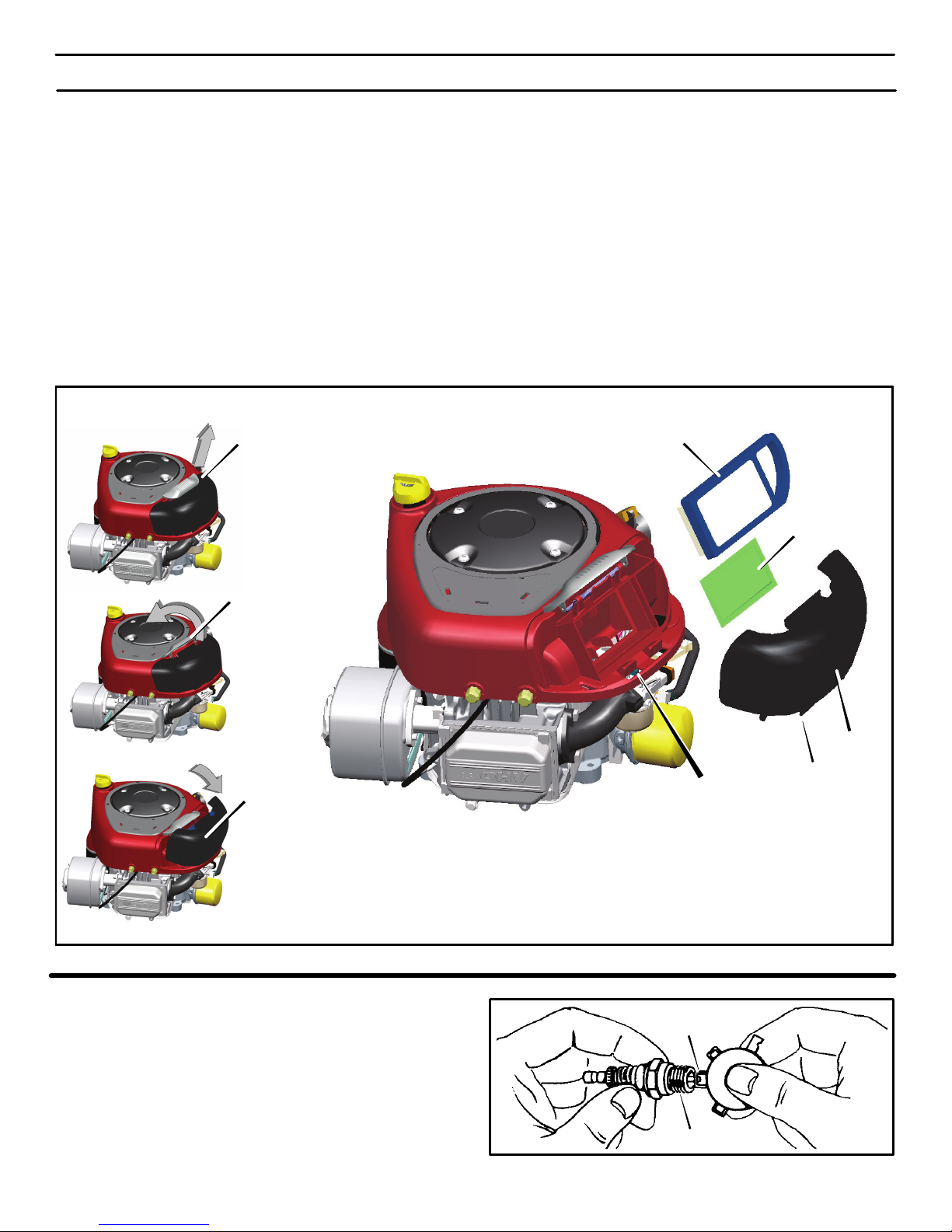
HOW TO SERVICE THE AIR FILTER
NOTE: Never run the engine with the air filters (air cleaner
cartridge, pre-cleaner) removed. The air filters will help protect
the engine against wear. For the correct replacement filter, see
the parts list for the engine.
CAUTION: Do not use pressurized air or solvents to clean
cartridge. Pressurized air can damage cartridge; solvents will
dissolve cartridge.
If a filter is stamped WASHABLE, it can be washed with warm water
and mild soap.
IMPORTANT: Rinse in tap water with SCREEN side up allowing
dirt and debris to filter out. Leave filter to dry overnight before
reinstalling.
Cartridge removal / installation
1. Pull up on the handle for the air cleaner cover. Rotate the handle toward the
engine (Figure 25).
2. Remove the cover
.
3. Carefully lift the air cleaner cartridge, and the pre-cleaner, if
equipped, from the blower housing.
4. To prevent debris from falling into the carburetor, carefully clean
the air cleaner base
.
5. Install a new pre-cleaner, if equipped, and air cleaner car-
tridge firmly into the air cleaner base.
6. Align the tabs on the cover with the slots on the blower housing and install the cover.
7. To secure the cover, rotate the handle forward and push down.
Figure 25
Pull Handle
Rotate Handle
Remove Cover
Air Cleaner Cartridge
Pre-Cleaner
Slots
Cover
Tabs
HOW TO CHECK THE SPARK PLUG
1. Check the gap of the spark plug with a feeler gauge
(Figure 26). The correct gap is 0.030”.
2. For easy starting and good performance, replace the spark
plug every season or 100 hours of use.
Feeler Gauge
0.030”
Figure 26
Spark Plug
400150
Page 28
SERVICE AND ADJUSTMENT
28
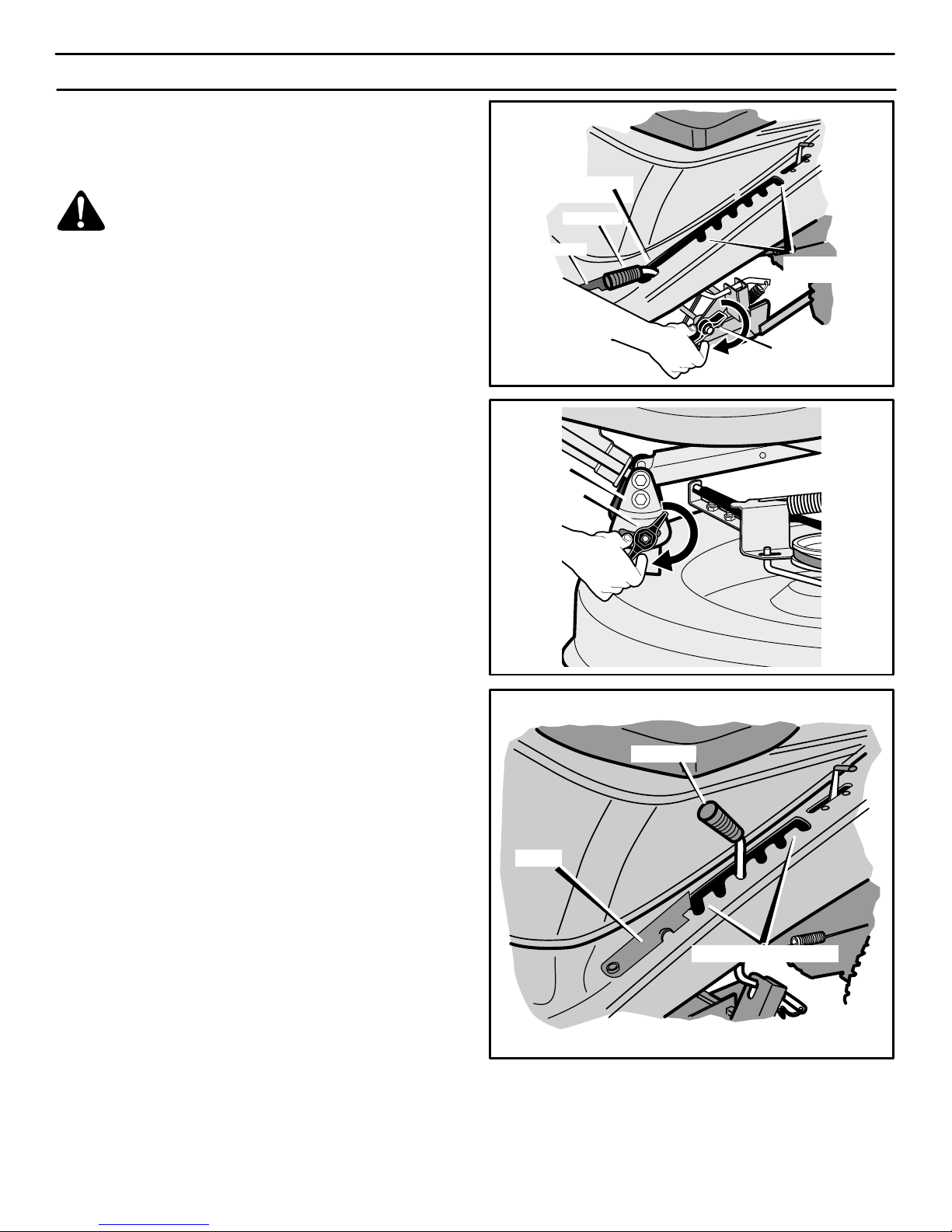
HOW TO LEVEL THE MOWER HOUSING
If the mower housing is level, the blade will cut easier and the lawn
will look better.
WARNING: Before you make an inspection, adjustment, or repair to the unit, disconnect the wire to the
spark plug. Remove the spark plug wire to prevent
the engine from starting by accident.
1. Make sure the unit is on a hard flat surface.
2. Check the air pressure in the tires. If the air pressure is incorrect, the mower housing will not cut level. The correct air pressure is shown on the side of the tire.
3. Make sure the attachment clutch is in the DISENGAGE
position.
4. Open the cover (see Figure 27).
5. Move the lift lever to the LEVEL ADJUSTMENT position (see
Figure 27).
6. Loosen the front and rear adjuster knobs (see Figure 27 and
Figure 28). Make sure both sides of the mower housing are setting on a flat surface.
7. Make sure that the adjuster plate is loose and can easily move
up or down (see Figure 28).
8. Tighten the front and rear adjuster knobs. Make sure the ad-
juster knobs are tight. If necessary, use a wrench to tighten the
adjuster knobs. Tighten to a torque of 10 foot pounds (13,5
N−m).
9. Raise the lift lever from the LEVEL ADJUSTMENT position to
a CUTTING HEIGHT position (Figure 29).
10. Close the cover.
11. Attach the spark plug wire to the spark plug.
12. Mow for a short distance. If the height of cut is not level, repeat
the above steps.
CAUTION: Do not operate with the mower housing in the
LEVEL ADJUSTMENT position. If you operate in the LEVEL
ADJUSTMENT position, the mower housing and blades can be
damaged.
Figure 27
Level Adjustment
Position
Cutting Height
Positions
Cover
Lift Lever
Rear Adjuster Knob
Figure 28
Front Adjuster
Knobs
Adjuster
Plate
Figure 29
Cutting Height Positions
Cover
Lift Lever
400150
Page 29
SERVICE AND ADJUSTMENT
29
HOW TO ADJUST THE ATTACHMENT CLUTCH
WARNING: To prevent an injury, the attachment
clutch must operate correctly.
In normal usage, the attachment clutch will not require an
adjustment. However, if the cutting performance decreases or the
quality of cut is poor, make the following changes.
1. When you mow, make sure the throttle control in in the FAST
position.
2. Move the attachment clutch to the DISENGAGE position
(Figure 30).
3. Stop the engine. Disconnect the wire from the spark plug.
Attachment Clutch
Engage Position
Disengage
Position
Figure 30
4. Check the blade(s). Keep a sharp edge on the blade(s). A blade
that is not sharp will cause the tips of the grass to become
brown.
5. If the quality of cut has not improved, replace the mower drive
belt. See “How To Replace The Mower Drive Belt”. If replacing
the belt does not correct the problem, take the unit to a Sears
or other qualified service center.
6. Move the attachment clutch to the DISENGAGE position.
Stop the engine. Disconnect the wire from the spark plug.
7. Check the operation of the blade brake. Rotate the pulley with
your hand. Make sure the brake pad is pressed tightly against
the pulley (Figure 31).
WARNING: If the brake pad does not press tightly
against the pulley, take the unit to a Sears or other qualified service center.
8. Move the attachment clutch to the ENGAGE position.
9. Check the pad for the blade brake. If the pad is excessively
worn or damaged, replace the brake pad assemblies. Correct
replacement parts and assistance are available from a Sears
service center.
10. Attach the wire to the spark plug. Mow for a short distance and
again check the operation of the attachment clutch.
11. When you move the attachment clutch to the DISENGAGE
position, all movement will stop within five seconds. If there is
movement of the belt or the blades continue to rotate, engage
and disengage the attachment clutch five times to remove
any excess rubber from a new mower drive belt. If you need
assistance, take the unit to a Sears or other qualified service
center.
Figure 31
Blade Brake
(Pad Against Pulley)
400150
Page 30
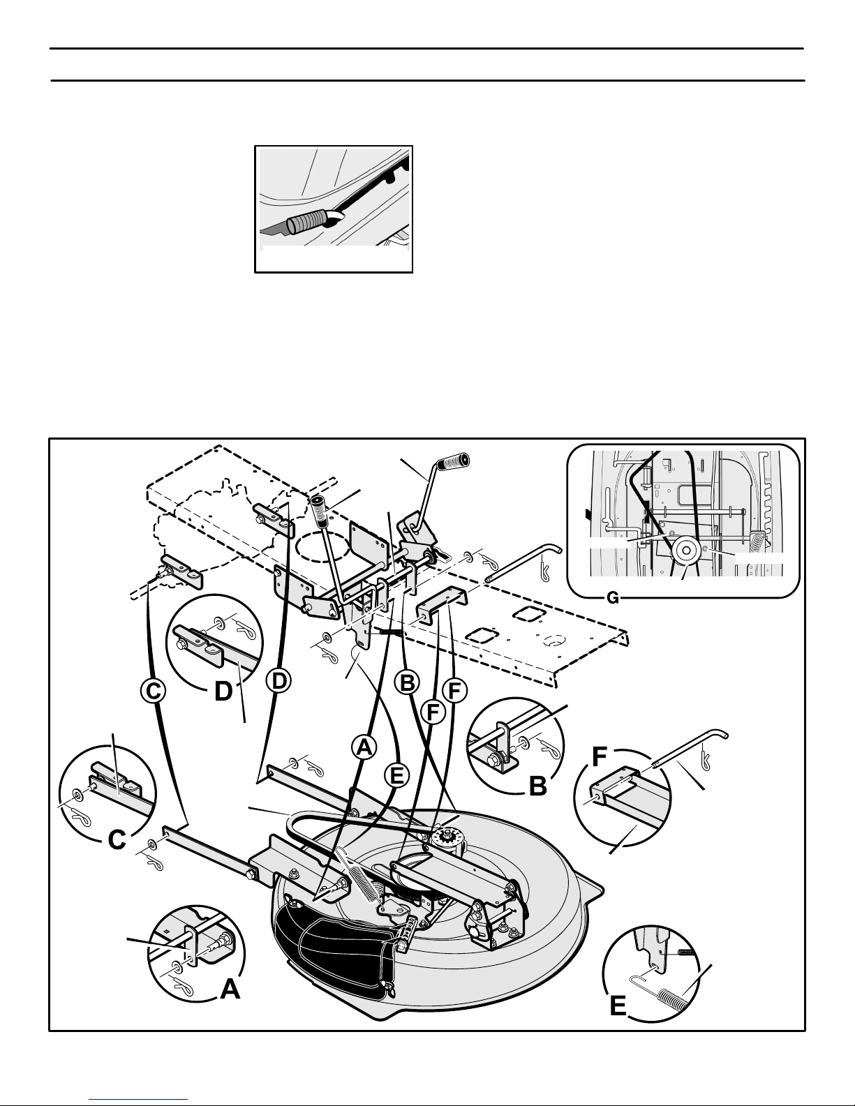
Level Adjustment
Position Figure 32
SERVICE AND ADJUSTMENT
30
HOW TO REMOVE THE MOWER HOUSING
1. Move the attachment clutch to the DISENGAGE position.
2. Move the lift lever to the level adjustment position (Figure 32).
NOTE: Make sure the lift lever
is locked in the LEVEL
ADJUSTMENT position.
3. Remove the hair pins and the
washers from the rear suspen-
sion arms (Figure 33). See illustrations “C” and “D”.
4. Remove the hair pins and washers from the suspension links.
See illustrations “A” and “B”.
5. Disconnect the extension spring from the blade control rod.
See illustration “E”.
6. Disconnect the front hanger from the frame support. See
illustration “F”.
7. Remove the mower drive belt from the stack pulley. See
illustration “G”.
8. Pull the mower housing away from the right side of the unit.
9. To operate without the mower housing, move the lift lever to the
TOP position.
HOW TO INSTALL THE MOWER HOUSING
1. Push the mower housing under the right side of the unit.
2. Put the mower drive belt around the stack pulley. Make sure
the “V” side of the mower drive belt is against the stack pulley.
Also, make sure the mower drive belt is not twisted.
3. Attach the front hanger to the frame support with the hanger
rod. Fasten with the fasteners as shown. See illustration “F”.
4. Make sure the mower drive belt is between the stack pulley
and the two belt guides. See illustration “G”.
5. Attach the suspension links to the lifter assembly. Fasten
with the washers and hair pins. See illustrations “A” and “B”.
6. Attach the rear suspension arms to the suspension brackets.
Fasten with the washers and hair pins. See illustrations “C” and
“D”.
7. Attach the extension spring to the blade control rod. See
illustration “E”.
8. Move the attachment clutch to the ENGAGE position. Make
sure the mower drive belt is inside all the belt guides and is
also below the spacer tube.
9. Make sure the mower housing is level. See the instructions on
“How To Level The Mower Housing”.
10. Check the operation of the attachment clutch. See the instruc-
tions on “How To Adjust The Attachment Clutch”.
Lifter
Assembly
Attachment
Clutch
Hanger Rod
Mower
Drive Belt
Lift Lever
Figure 33
Extension
Spring
Suspension
Link
Adjuster
Arm
Adjuster
Arm
BeltGuide
Stack Pulley
Suspension
Link
BeltGuide
Front Hanger
Spacer Tube
400150
Page 31
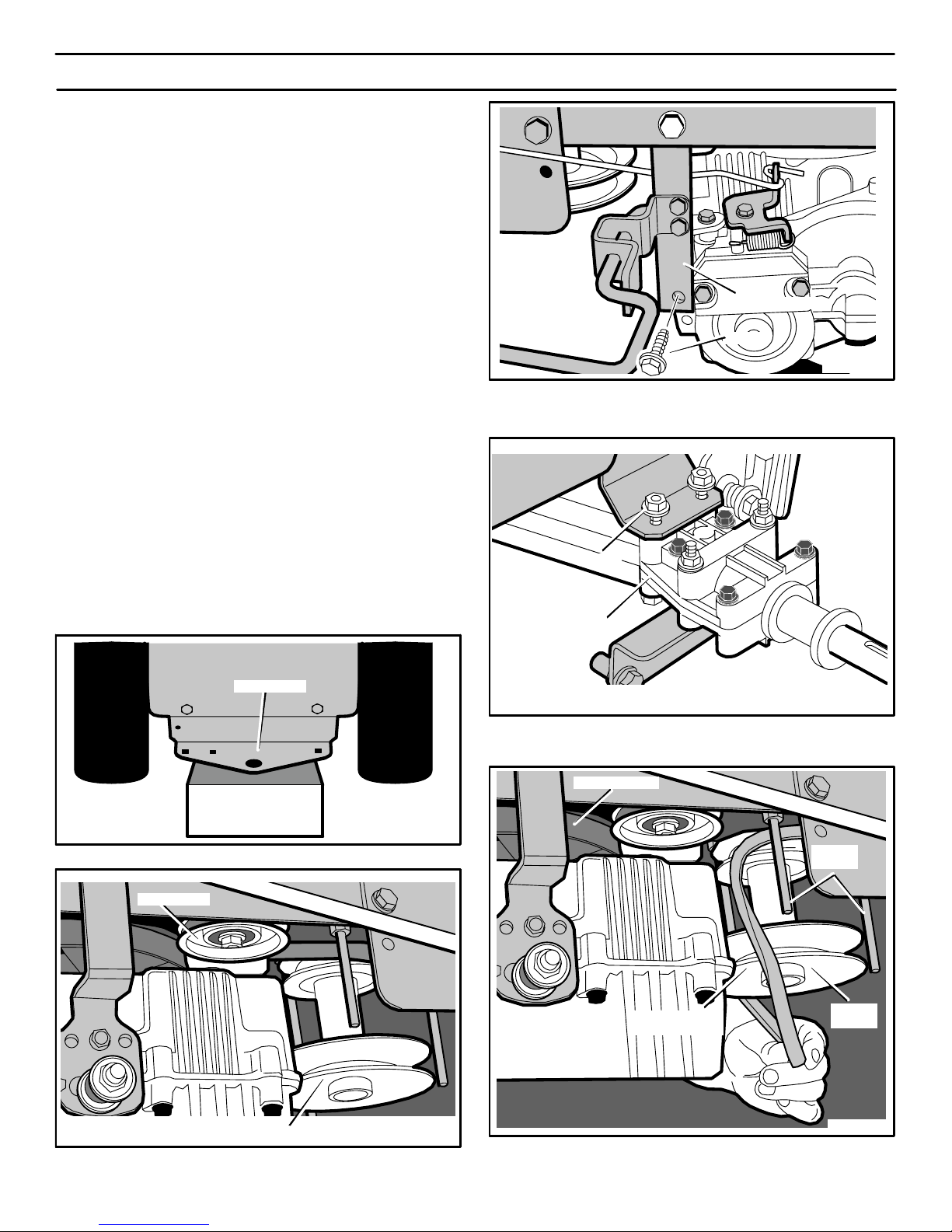
SERVICE AND ADJUSTMENT
31
HOW TO REPLACE
THE MOTION DRIVE BELTS
ENGINE DRIVE BELT REMOVAL
1. Remove the mower housing. See the instructions on “How To
Remove The Mower Housing”.
2. Set the rear hitch on a 10 to 12 inch block. The block must be
high enough to raise the rear wheel of off the ground (see
Figure 34).
3. Remove the rear wheels.
4. Remove the idler pulley (see Figure 35).
5. Remove the bolt from the torque strap (see Figure 36).
6. Loosen the nuts from each side of the transmission (see
Figure 37). Do not remove the nuts. Loosen until the nuts are
at the top of the bolts.
7. Slip the rear of the motion drive belt over the drive pulley and
out the front of the transmission. Then, pull the motion drive
belt down between the belt guides and the stack pulley (see
Figure 38).
8. To install, reverse the above steps.
9. Install the mower housing. See the instructions on “How To
Install The Mower Housing”.
10. Check the operation of the drive system. See “How To Check
And Adjust The Clutch” and also “How To Adjust The Speed
Control Lever”.
Figure 34
10 to 12 Inch
High Block
Rear Hitch
Figure 35
Stack Pulley
Idler Pulley
Figure 36
Torque Strap
Bolt
Figure 37
Nut
Transmission
Figure 38
Drive Pulley
Motion Drive
Belt
Stack
Pulley
Belt
Guide
400150
Page 32
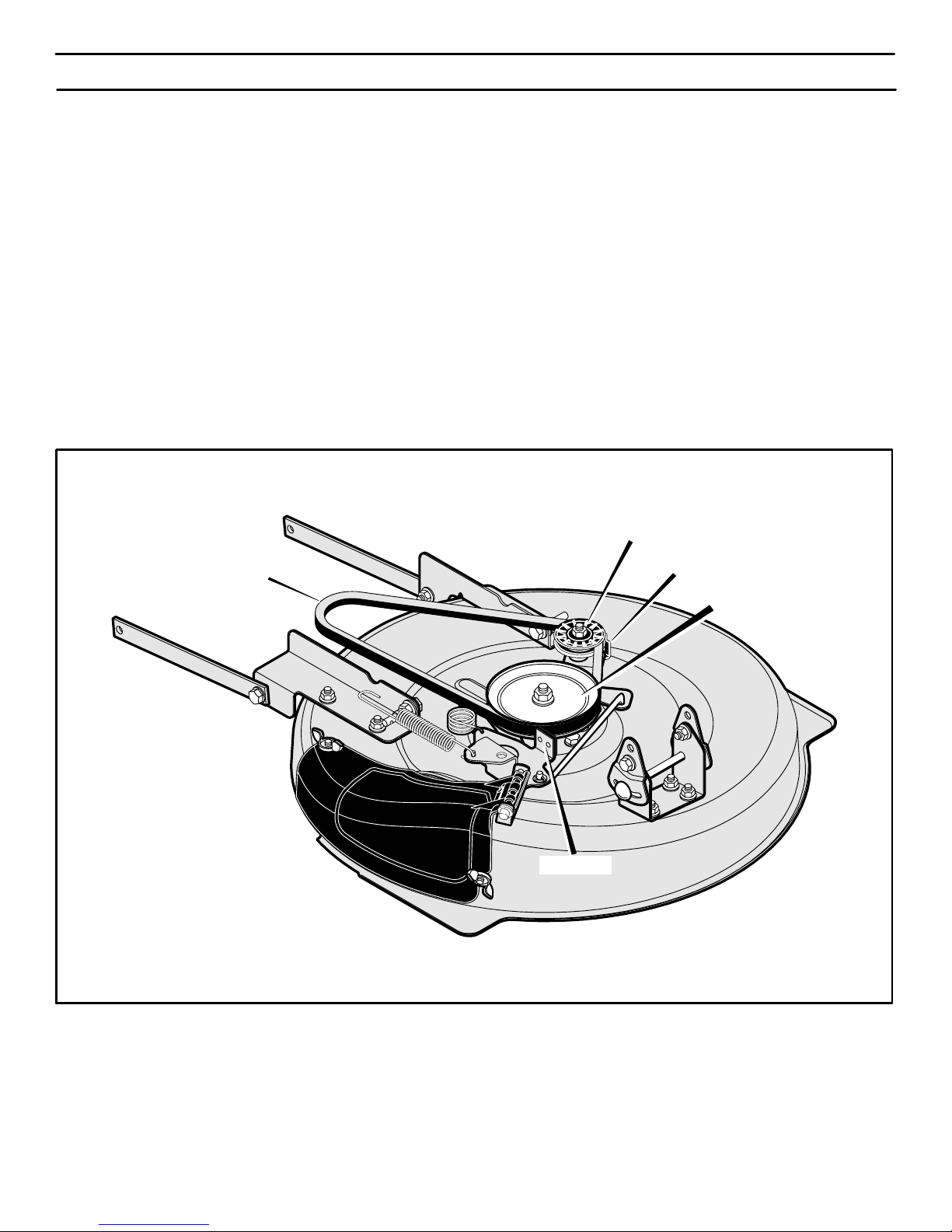
SERVICE AND ADJUSTMENT
32
HOW TO REPLACE THE MOWER DRIVE BELT
1. Remove the mower housing. See the instructions on “How To
Remove The Mower Housing”.
2. Pull the belt retainer away from the idler pulley and remove
the mower drive belt (Figure 39).
3. Pull the brake pad away from the jackshaft pulley and remove
the mower drive belt.
NOTE: Replace the mower drive belt with an original
equipment belt purchased from a Sears Service Center.
4. Install the new mower drive belt. Pull the brake pad away
from the jackshaft pulley. Put the mower drive belt around
the jackshaft pulley.
5. Pull the belt retainer away from the idler pulley. Put the mow-
er drive belt around the idler pulley.
6. Make sure the “V” side of the mower drive belt is against the
jackshaft pulley and the idler pulley.
7. Install the mower housing. See the instructions on “How To
Install The Mower Housing”.
8. Before you mow, check the attachment clutch. See the instructions on “How To Adjust The Attachment Clutch”.
Figure 39
Mower Drive Belt
Belt Retainer
Brake Pad
Idler Pulley
Jackshaft Pulley
400150
Page 33
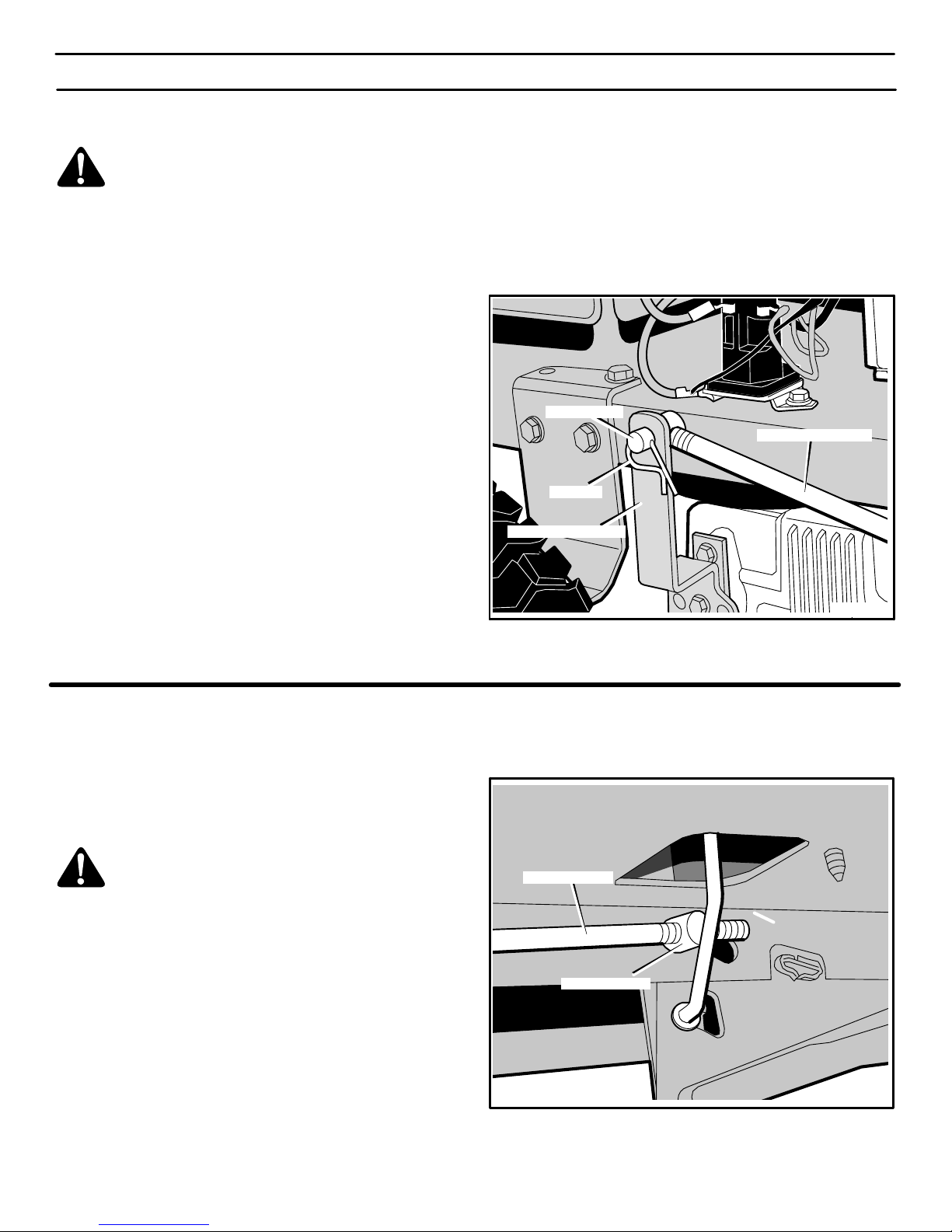
SERVICE AND ADJUSTMENT
33
HOW TO ADJUST THE SPEED CONTROL LEVER
WARNING: Before you make an inspection, adjustment, or repair to the unit, disconnect the wire to the
spark plug. Remove the wire from the spark plug to
prevent the engine from starting by accident.
If a drive belt becomes worn or after the installation of a new drive
belt, the speed control lever may need an adjustment. When the
speed control lever is moved to the NEUTRAL position, the unit
must come to a complete stop. If the unit does not come to a
complete stop, adjust as follows.
1. Move the speed control lever to the NEUTRAL position.
2. Remove the hair pin from the adjuster nut (see Figure 40).
3. Disconnect the adjuster nut from the hydro actuator arm.
4. If the unit was slowly moving forward when the speed control
lever was in the NEUTRAL position, then turn the adjuster nut
clockwise (forward) one or two turns. This will decrease the
length of the speed control rod.
5. If the unit was slowly moving rearward when the speed control
lever was in the NEUTRAL position, then turn the adjuster nut
counterclockwise (backward) one or two turns. This will in-
crease the length of the speed control rod.
6. Assemble the adjuster nut to the hydro actuator arm and
secure with the hair pin.
7. Connect the wire to the spark plug. Start the engine and test
drive the unit. Make sure that the unit will come to a complete
stop when the speed control lever is put in the NEUTRAL position.
Figure 40
Hydro Actuator Arm
Speed Control Rod
Adjuster Nut
Hair Pin
HOW TO CHECK AND ADJUST THE CLUTCH
If the engine drive belt is loose, the clutch will slip when; (1) going
up a hill, (2) pulling a heavy load, or (3) the unit will not move forward.
Adjust the clutch as follows.
WARNING: Before you make an inspection, adjustment, or repair to the unit, disconnect the wire to the
spark plug. Remove the wire from the spark plug to
prevent the engine from starting by accident.
1. Remove the hair pin and washer from the adjustable nut on
the clutch rod (Figure 41).
2. Turn the adjuster nut counterclockwise (forward) to increase
the movement of the pedal and tighten the belt.
3. Assemble the adjustable nut and fasten with the washer and
cotter pin.
4. Connect the wire to the spark plug. Start the engine and test
drive the unit. Make sure that the clutch does not slip or that the
belt does not slip.
5. If the belt still slips after the clutch has been adjusted, then the
motion drive belt is worn or damaged and must be replaced.
See “How To Replace The Motion Drive Belt”.
Adjustable Nut
Clutch Rod
Figure 41
400150
Page 34
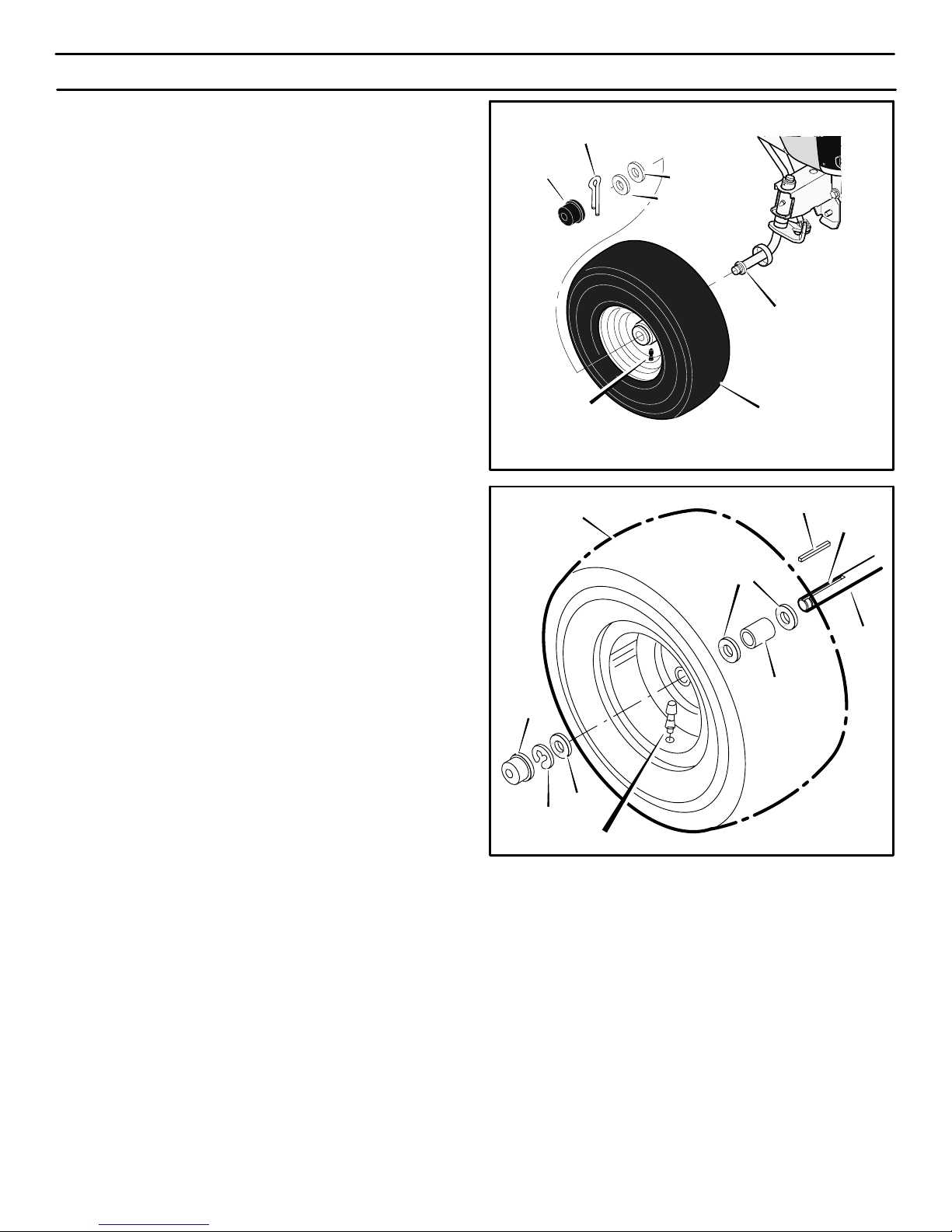
SERVICE AND ADJUSTMENT
34
HOW TO INSTALL THE WHEELS
If the wheels must be removed for service, make sure they are
installed as follows.
Front Wheel
1. Make sure the valve stem is to the outside of the tractor. Slide
the front wheel on the spindle (See Figure 42).
2. Fasten the front wheel with washer and cotter pin. Bend the
ends of the cotter pin apart to keep the front wheel on the
spindle.
3. If your model has hub caps, install the hub caps. Make sure
the washers hold the hub caps in place.
Rear Wheel
1. Install the washers and spacer onto the axle as shown in
Figure 43.
2. Mount the square key in the key slot (See Figure 43).
3. Make sure the valve stem is to the outside of the tractor. Align
the slot in the rear wheel with the square key. Slide the rear
wheel on the axle.
4. Fasten the rear wheel with washer and e−ring.
5. If your model has hub caps, install the hub caps. Make sure
the washers hold the hub caps in place.
Figure 42
Front Wheel
Spindle
Valve Stem
Washer
Washer
Hub Cap
Cotter Pin
Figure 43
E−Ring
Washer
Hub Cap
Washer
Spacer
Square Key
Valve Stem
Key Slot
Axle
Rear Wheel
400150
Page 35
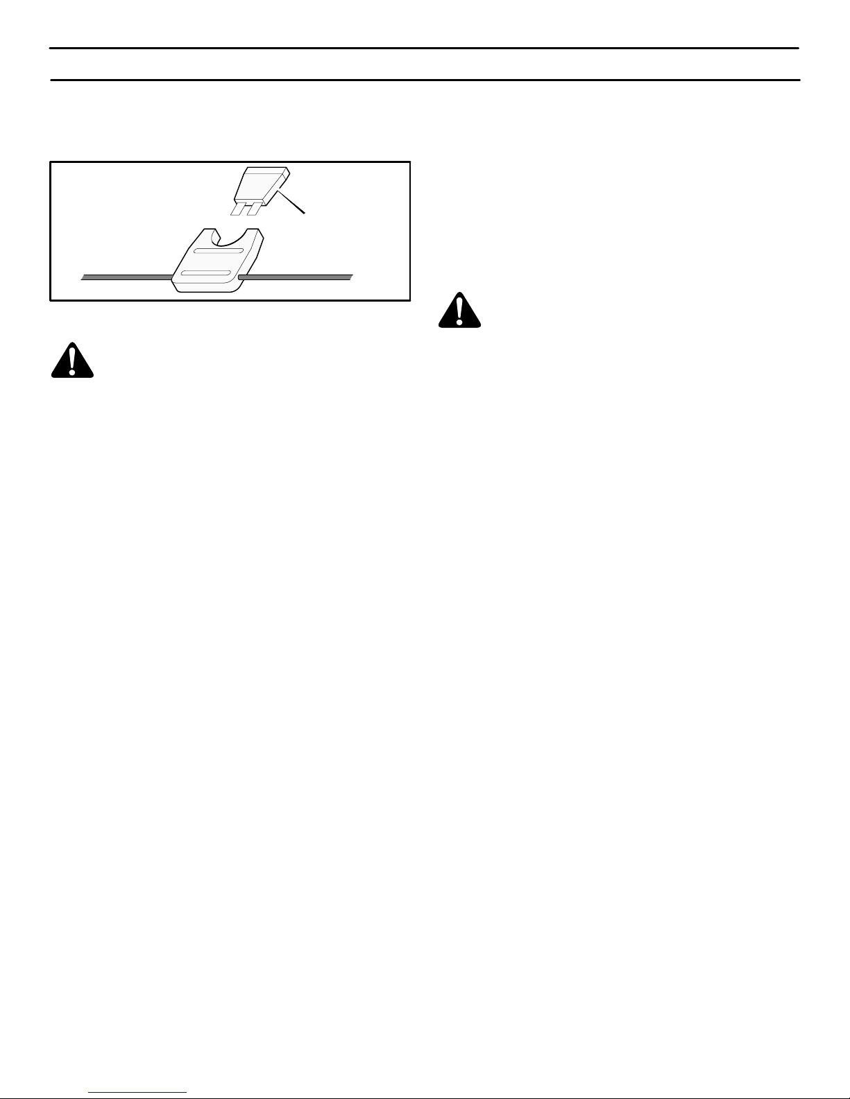
SERVICE AND ADJUSTMENT
35
HOW TO REPLACE THE FUSE
If the fuse is blown, the engine will not start. The location of the fuse
is next to the battery. Remove the fuse and replace with a 15 amp.
automotive fuse (Figure 44).
Figure 44
15 amp
Automotive Fuse
HOW TO CLEAN THE MOWER HOUSING
WARNING: Before you clean the mower housing,
stop the engine and disconnect the wire to the spark
plug.
Grass and other debris on top of the mower housing can keep the
belt from working correctly. For safety and correct operation,
frequently clean the top of the mower housing. Remove grass and
debris from around the pulleys and other moving parts.
1. Move the lever for the attachment clutch to the ENGAGE position.
2. Clean the top of the mower housing.
3. Move the lever for the attachment clutch to the DISENGAGE
position.
4. Again clean the top of the mower housing.
5. After you cut the grass, clean the bottom of the mower housing.
FRONT WHEEL ALIGNMENT
The alignment of the front wheels cannot be adjusted. If the steering
is damaged and the alignment has changed, take the unit to your
nearest Sears Service Center.
STORAGE (over 30 days)
At the end of each year, prepare the unit for storage as follows.
GENERAL INSPECTION
1. Inspect the belts. If the belts are damaged or worn, replace with
replacement belts from the factory. See the belt replacement
instructions in the Service And Adjustment section.
2. Make sure all nuts, bolts and screws are tight. Inspect moving
parts for damage, breakage and wear. Replace if necessary.
MOWER HOUSING
1. Clean the mower housing. See “How To Clean The Mower
Housing”.
LUBRICATE THE UNIT
See the “Where To Lubricate” instructions in the Maintenance
section.
THE ENGINE
1. Clean the dirt and grass from the engine.
2. Change the oil. See the instructions, “How To Change The Oil”.
3. Check the air screen. See the instructions, “How To Clean The
Cooling System”.
4. Check the spark plug. See the instructions, “How To Check The
Spark Plug”.
THE FUEL SYSTEM
WARNING: Do not drain the gasoline inside a building or near a fire. Do not smoke because the fumes
from the fuel can cause an explosion.
It is important to prevent gum deposits from forming in essential fuel
system parts such as the carburetor, fuel filter, fuel hose or tank
during storage. Also, alcohol blended fuels (called gasohol or using
ethanol or methanol) can attract moisture which leads to separation
and formation of acids during storage. Acidic gas can damage the
fuel system of an engine while in storage.
To avoid engine problems, the fuel system should be emptied before
storage of 30 days or longer. Follow these instructions:
NOTE: Fuel stabilizer (like STA-BIL) is an acceptable
alternative in reducing the formation of fuel gum in the fuel tank
and the gasoline storage container. Always follow the mix ratio
located on the container of stabilizer. Run the engine at least 3
minutes after adding the stabilizer to allow the stabilizer to
reach the carburetor. Do not drain the fuel tank and carburetor
if stabilizer is used.
If you do not use a stabilizer, do the following:
1. Start the engine.
2. Run the engine until the fuel tank and the carburetor are out of
fuel and the engine stops.
3. Do not leave fuel in the fuel tank or the carburetor. The fuel can
damage the function of the fuel system.
4. After storage, make sure you use fresh fuel.
THE BATTERY
1. Remove the battery.
2. Clean the battery terminals of any deposits.
3. Charge the battery. See the instructions on “How To Charge
The Battery”.
4. Store the battery in a cool, dry place.
NOTE: After a long time in storage, charge the battery.
400150
Page 36

TROUBLESHOOTING CHART
36
PROBLEM: The engine will not start.
1. Follow the steps, “How To Start The Engine” in this book.
2. Electric−Start Models: Clean the battery terminals. Tighten the
cables.
3. Drain the fuel tank. Clean the fuel line. Replace the fuel filter.
4. Remove the spark plug(s). Move the throttle to the SLOW position. Turn the ignition key to the ON position. Try to start the engine several times. Install the spark plug.
5. Replace the spark plug.
6. Adjust the carburetor.
PROBLEM: The engine will not turn over.
1. Follow the steps, “How To Start The Engine” in this book.
2. Electric−Start Models: Check the level of the acid in the battery.
If needed, add water. Charge the battery.
3. Replace the fuse.
4. Check the wiring harness for damage or a loose connection.
Repair the damaged wire.
5. Electric−Start Models: replace the solenoid. Recoil−Start Models: replace the module.
PROBLEM: The engine is difficult to start.
1. Adjust the carburetor.
2. Replace the spark plug.
3. Replace the fuel filter.
PROBLEM: The engine does not run smooth or has a
loss of power.
1. Check the oil.
2. Clean the air filter.
3. Clean the air screen.
4. Replace the spark plug.
5. The engine is working too hard. Use a lower gear.
6. Adjust the carburetor.
7. Replace the fuel filter.
PROBLEM: The engine does not run smooth at fast
speed.
1. Replace the spark plug.
2. Adjust the throttle control.
3. Clean the air filter.
4. Replace the fuel filter.
PROBLEM: The engine stops when the blades are
engaged.
1. Check the wiring harness for damage or a loose connection.
Repair the damaged wire.
2. Transmission is in reverse. Before operating in reverse, move
the blade rotation control to the DISENGAGED position.
PROBLEM: On slopes, the engine stops.
1. Mow up and down slopes. Never mow across a slope.
PROBLEM: The engine will not idle.
1. Replace the spark plug.
2. Clean the air filter.
3. Adjust the carburetor.
4. Adjust the throttle control.
5. Drain the fuel tank. Clean the fuel line. Replace the fuel filter.
PROBLEM: A hot engine causes a decrease in power.
1. Clean the air screen.
2. Check the oil.
3. Adjust the carburetor.
4. Replace the fuel filter.
PROBLEM: Excessive vibration.
1. Replace the blade.
2. Check for loose engine bolts.
3. Decrease the air pressure in the tires.
4. Adjust the carburetor.
5. Check for a damaged belt or damaged pulley. Replace the
damaged parts.
PROBLEM: The grass does not discharge correctly.
1. Stop the engine. Clean the mower housing.
2. Raise the height of cut.
3. Replace or sharpen the blade(s).
4. Move the shift lever to a slower speed.
5. Move the throttle control to the FAST position.
6. Replace the spring for the blade idler.
PROBLEM: The mower housing does not cut level.
1. Check the air pressure in the tires.
2. Adjust the level of the mower housing.
3. Check the front axle. If the front axle does not freely pivot, loosen the axle bolt(s).
PROBLEM: The mower blades will not rotate.
1. Check the mower drive belt. Make sure the belt is installed correctly.
2. Replace the mower drive belt.
PROBLEM: The unit will not move when the clutch is
engaged.
1. Check the motion drive belt. Make sure the belt is installed
correctly.
2. Adjust the clutch.
3. Replace the motion drive belt.
PROBLEM: The unit moves slower or stops when the
clutch is engaged.
1. Adjust the clutch.
2. Replace the motion drive belt.
PROBLEM: When the clutch/brake pedal is released, belt
noise can be heard.
1. Temporary belt noise does not change the operation of the unit.
If belt noise is continuous, check the routing of the belt. Make
sure the belt is inside all belt guides.
2. If the noise is continuous, adjust the clutch.
PROBLEM: The rear wheels spin over uneven terrain.
1. Check the front axle. If the front axle does not freely pivot, loosen the axle bolt(s).
PROBLEM: The engine stops when the operator leaves
the seat.
1. This is normal. The operator presence system is designed to
allow operation only if the operator is in the seat.
PROBLEM: The engine stops when selecting reverse
travel.
1. Before selecting reverse travel, move the blade rotation control
to the DISENGAGE position. See the Operation section for details.
PROBLEM: The transaxle is difficult to shift between
gears with the engine running and the clutch depressed.
1. Check the clutch adjustment to make sure the belt stops when
the clutch pedal is depressed with the transaxle in (N) neutral.
2. Check the belt guides around the transaxle drive pulley. Make
sure the belt guides do not touch the pulley.
400150
Page 37

37
Sears, Roebuck and Co., USA (Sears), the California Air Resources Board (CARB)
and the United States Environmental Protection Agency (U.S. EPA)
Emissions Control System Warranty Statement (Owner’s Defect Warranty Rights and Obligations)
The California Air Resources Board (CARB), U.S. EPA and Sears
are pleased to explain the Emissions Control System Warranty on
your small off-road engine (SORE). In California, new small off-road
engines model year 2006 and later must be designed, built and
equipped to meet the State’s stringent anti-smog standards.
Elsewhere in the United States, new non-road, spark-ignition engines certified for model year 1997 and later must meet similar standards set forth by the U.S. EPA. Sears must warrant the emissions
control system on your engine for the periods of time listed below,
provided there has been no abuse, neglect or improper maintenance of your small off-road engine.
Your emissions control system includes parts such as the carburetor, air cleaner, ignition system, fuel line, muffler and catalytic converter. Also included may be connectors and other emissions
related assemblies.
Where a warrantable condition exists, Sears will repair your small
off-road engine at no cost to you including diagnosis, parts and labor.
Sears, Roebuck and Co. Emissions Control Defects Warranty Coverage
Small off-road engines are warranted relative to emissions control parts defects for a period of two years, subject to provisions set forth below.
If any covered part on your engine is defective, the part will be repaired or replaced by Sears.
Owner’s Warranty Responsibilities
As the small off-road engine owner, you are responsible for the performance of the required maintenance listed in your Operating and
Maintenance Instructions. Sears recommends that you retain all
your receipts covering maintenance on your small off-road engine,
but Sears cannot deny warranty solely for the lack of receipts or for
your failure to ensure the performance of all scheduled maintenance.
As the small off-road engine owner, you should however be aware
that Sears may deny you warranty coverage if your small off-road
engine or a part has failed due to abuse, neglect, improper maintenance or unapproved modifications.
You are responsible for presenting your small off-road engine to an
Authorized Sears Service Dealer as soon as a problem exists.
The undisputed warranty repairs should be completed in a reasonable amount of time, not to exceed 30 days.
If you have any questions regarding your warranty rights and responsibilities, you should contact a Sears Service Representative at
1-800−469−4663.
The emissions warranty is a defects warranty. Defects are judged
on normal engine performance. The warranty is not related to an
in-use emissions test.
Sears, Roebuck and Co. Emissions Control Defects Warranty Provisions
The following are specific provisions relative to your Emissions Control Defects Warranty Coverage. It is in addition to the Sears engine
warranty for non-regulated engines found in the Operating and Maintenance Instructions.
1. Warranted Parts
Coverage under this warranty extends only to the parts listed
below (the emission control systems parts) to the extent these
parts were present on the engine purchased.
a. Fuel Metering System
¯ Cold start enrichment system
¯ Carburetor and internal parts
¯ Fuel Pump
b. Air Induction System
¯ Air cleaner
¯ Intake manifold
c. Ignition System
¯ Spark plug(s)
¯ Magneto ignition system
d. Catalyst System
¯ Catalytic converter
¯ Exhaust manifold
¯ Air injection system, Pulse valve
e. Miscellaneous Items
¯ Vacuum, temperature, position, time sensitive valves
and switches
¯ Connectors and assemblies
2. Length of Coverage
Sears warrants to the initial owner and each subsequent pur-
chaser that the Warranted Parts shall be free from defects in
materials and workmanship which caused the failure of the Warranted Parts for a period of two years from the date the engine
is delivered to a retail purchaser.
3. No Charge
Repair or replacement of any Warranted Part will be performed
at no charge to the owner, including diagnostic labor which
leads to the determination that a Warranted Part is defective, if
the diagnostic work is performed at an Authorized Sears Service Dealer. For emissions warranty service contact your nearest Authorized Sears Service Dealer as listed in the “Yellow
Pages” under “Engines, Gasoline,” “Gasoline Engines,” “Lawn
Mowers,” or similar category.
4. Claims and Coverage Exclusions
Warranty claims shall be filed in accordance with the provisions
of the Sears Engine Warranty Policy. Warranty coverage shall
be excluded for failures of Warranted Parts which are not original Sears parts or because of abuse, neglect or improper maintenance as set forth in the Sears Engine Warranty Policy. Sears
is not liable to cover failures of Warranted Parts caused by the
use of add-on, non-original, or modified parts. by the use of addon, non-original, or modified parts.
5. Maintenance
Any Warranted Part which is not scheduled for replacement as
required maintenance or which is scheduled only for regular
inspection to the effect of “repair or replace as necessary” shall
be warranted as to defects for the warranty period. Any Warranted Part which is scheduled for replacement as required
maintenance shall be warranted as to defects only for the period
of time up to the first scheduled replacement for that part. Any
replacement part that is equivalent in performance and durability
may be used in the performance of any maintenance or repairs.
The owner is responsible for the performance of all required
maintenance, as defined in the Sears Operating and Maintenance Instructions.
6. Consequential Coverage
Coverage hereunder shall extend to the failure of any engine
components caused by the failure of any Warranted Part still
under warranty.
400150
Page 38

38
Look For Relevant Emission Durability Period and
Air Index Information OnYour Engine Emission Label
Engines that are certified to meet the California Air Resources
Board (CARB) Tier 2 Emission Standards must display information
regarding the Emissions Durability Period and the Air Index. Briggs
& Stratton makes this information available to the consumer on our
emission labels. The engine emission label will indicate certification
information.
The Emissions Durability Period describes the number of hours
of actual running time for which the engine is certified to be
emissions compliant, assuming proper maintenance in accordance
with the Operating & Maintenance Instructions. The following
categories are used:
Moderate:
Engine is certified to be emission compliant for 125 hours of actual
engine running time.
Intermediate:
Engine is certified to be emission compliant for 250 hours of actual
engine running time.
Extended:
Engine is certified to be emission compliant for 500 hours of actual
engine running time. For example, a typical walk-behind lawn
mower is used 20 to 25 hours per year. Therefore, the Emissions
Durability Period of an engine with an intermediate rating would
equate to 10 to 12 years.
Certain Briggs & Stratton engines will be certified to meet the United
States Environmental Protection Agency (USEPA) Phase 2
emission standards. For Phase 2 certified engines, the Emissions
Compliance Period referred to on the Emissions Compliance label
indicates the number of operating hours for which the engine has
been shown to meet Federal emission requirements.
For engines less than 225 cc displacement.
Category C = 125 hours
Category B = 250 hours
Category A = 500 hours
For engines of 225 cc or more displacement.
Category C = 250 hours
Category B = 500 hours
Category A = 1000 hours
400150
Page 39
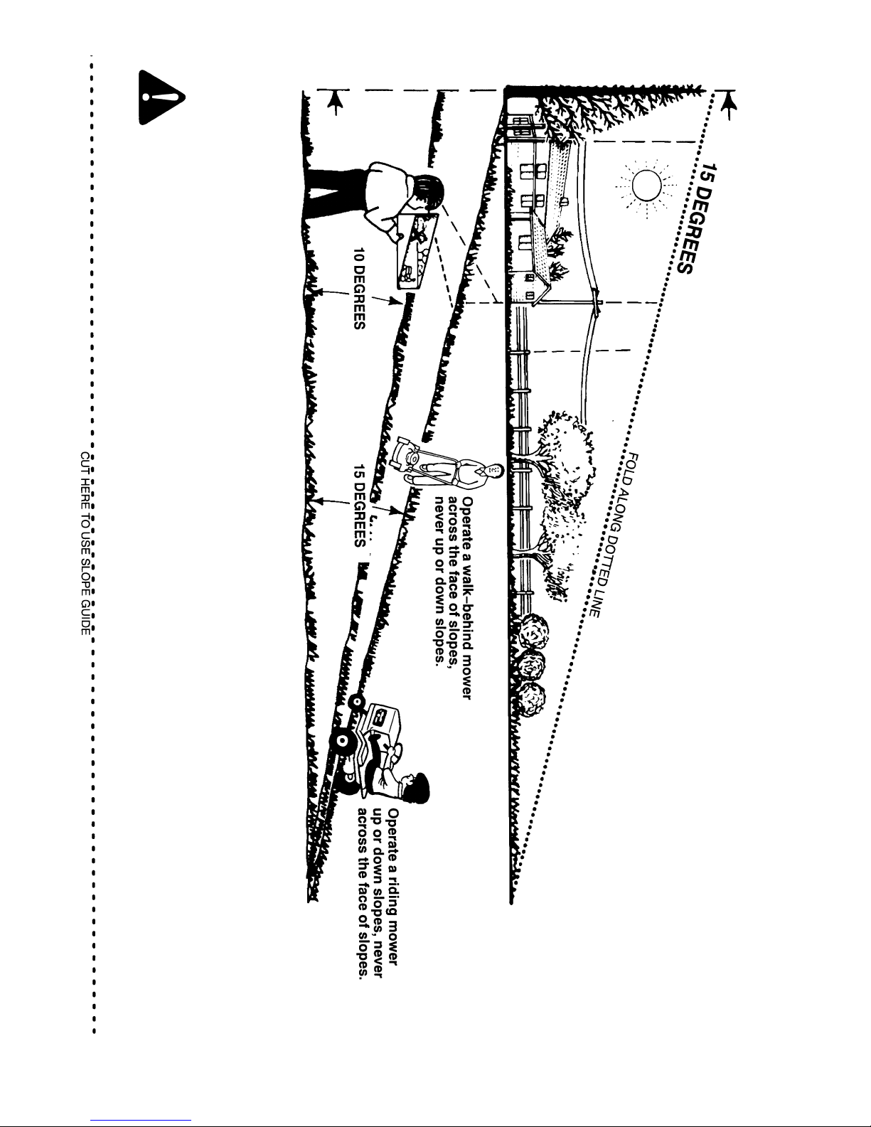
39
SLOPE GUIDE
Fold this page along dotted line indicated below. Hold page before you so that its left
edge is vertically parallel to a tree trunk or other upright structure. Sight across the
fold in the direction of the hill or slope you want to measure. Compare the angle of the
fold with the slope of the hill.
WARNING: To avoid possible serious injury, do not mow a slope that is greater than 15 degrees. If the riding mower is used with a
pull-behind or rear-mounted attachment, do not operate the unit on a slope that is greater than 10 degrees.
On a riding mower to determine if a slope is safe to mow: (1) disengage the blade(s), (2) put the unit in reverse, and (3) try to back straight up the
slope. If you can back up the slope, it is generally safe to mow. However, if you do not feel safe, or you are not completely sure, use this guide to
determine the slope angle.
400150
Page 40
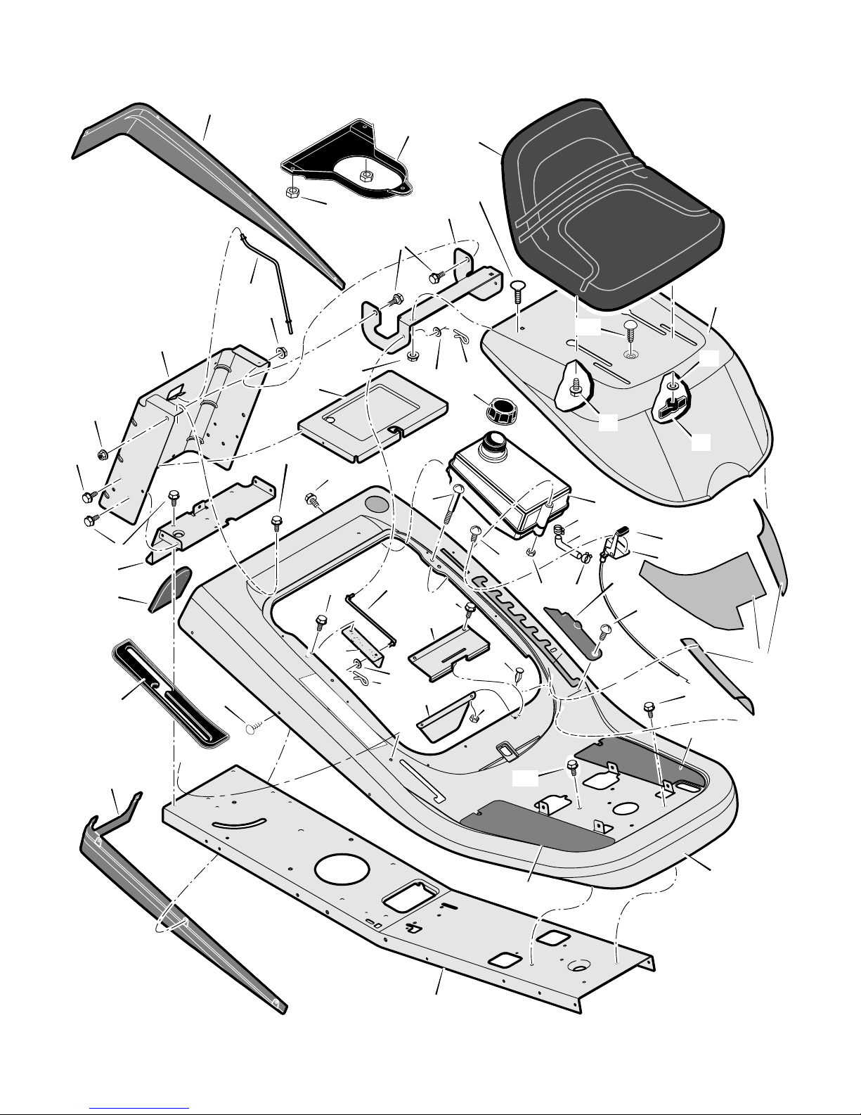
40
CHASSIS & HOOD
52
53
52
1
2
3
4
5
6
7
45
46
10
11
11
12
13
13
14
15
16
17
18
13
19
20
22
23
24
29
30
31
32
33
36
37
39
40
16
47
34
8
44
41
50
48
49
47
20
19
25
26
28
43
27
51
21
42
400150
MODEL 536.270321 REPAIR PARTS
Page 41

41
CHASSIS & HOOD
Key
No. Part No. Description
Key
No. Part No. Description
1 690566 Seat
2 1401379E701 Hood
3 017x47 Washer
4 1001054 Bolt, Wing
5 002x16 Bolt, Carriage
6 1401378E701 Bracket, Hinge
7 009x29 Bolt, Shoulder
8 009x56 Bolt, Shoulder
10 1401113 Rod, Battery
11 015x84 Nut, Flange
12 1401025E701 Plate, Rear
13 26x249 Screw
14 1401050E701 Plate, Hitch
15 1401087 Cover
16 26x263 Screw
17 1401076E701 Tray, Battery
18 015x79 Nut, Flange
19 017x37 Washer
20 0031x6 Pin, Hair
21 092317 Cap, Fuel Tank
22 1401404 Tank, Fuel
23 06x111 Screw
24 26x253 Screw
25 26x263 Screw
26 1401110 Rod, Hood Prop
27 1401282 Spring, Seat Deck
28 1401352E701 Bracket, Prop Rod
29 26x201 Screw
30 15x116 Nut, NY−Lock
31 1401248 Control, Throttle
32 1401084 Cover, Detent (Black)
33 009x47 Bolt, Shoulder
36 1401145 Footmat, Left (Black)
37 1401144 Footmat, Right (Black)
39 1401371E701 Frame
40 1401316E701 Deck, Seat
41 094744 Bumper
42 15x143 Nut
43 0025x2 Screw
44 7601129 Kit, Foil Heat Shield
45 1401073 Trim, Left
46 1401072 Trim, Right
47 0193x1 Fastener, Panel
48 1401380 Plenum
49 15x123 Nut, Hex 5/16−18
50 1401331 Cover, Long Black
51 1401401 Shield, Heat
52 095197 Clamp, Hose
400150
53 1401402 Line, Fuel
400150 Book, Instruction
MODEL 536.270321 REPAIR PARTS
Page 42
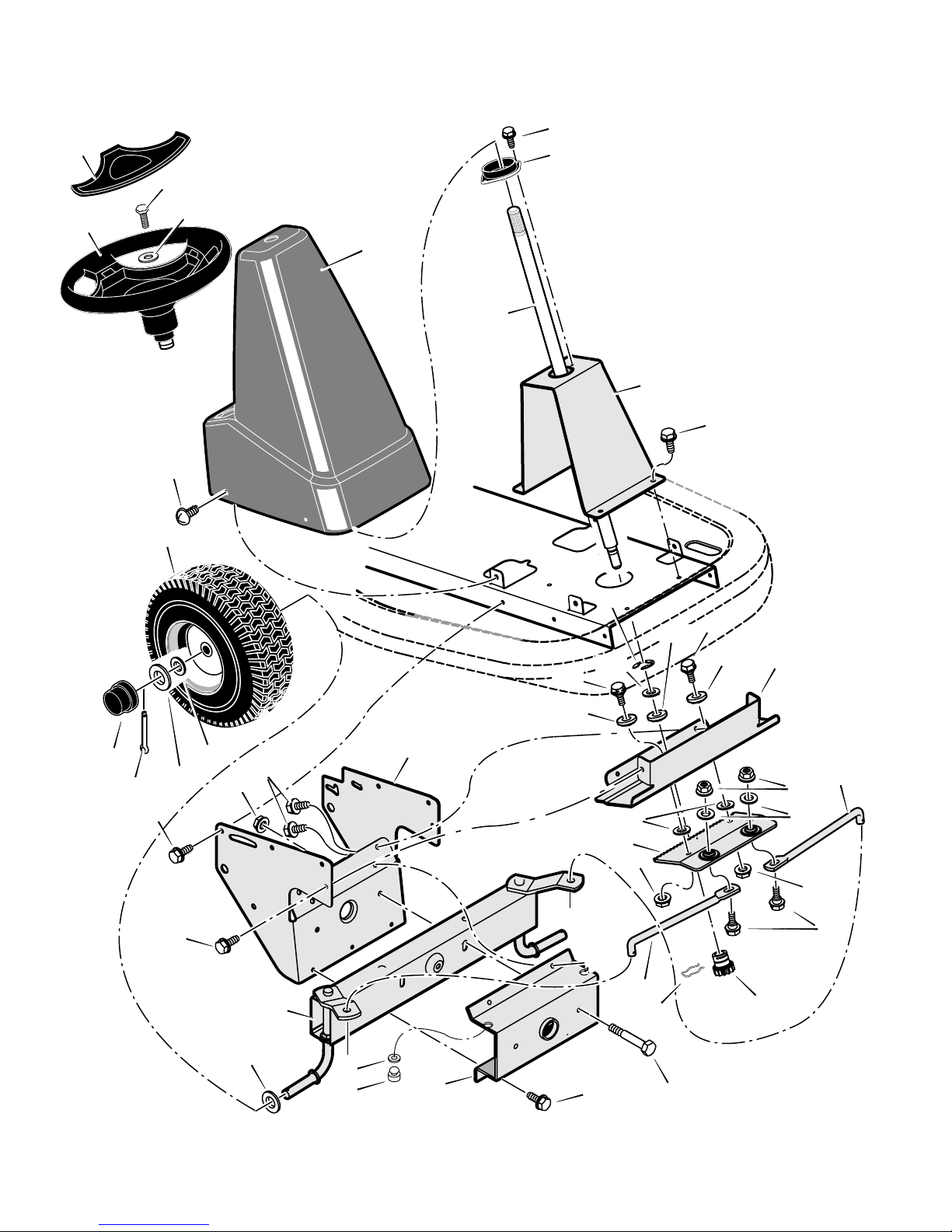
42
STEERING
3
4
5
7
8
9
9
9
9
10
11
12
13
14
15
10
12
16
17
17
18
19
20
24
22
25
27
28
34
29
30
31
32
33
35
23
38
14
26
9
21
40
39
1
2
41
43
400150
MODEL 536.270321 REPAIR PARTS
Page 43

43
STEERING
Key
No. Part No. Description
Key
No. Part No. Description
1 1001980 Wheel, Steering
2 1001982 Cover, Steering Wheel
3 1401067 Console, High (Black)
4 26x250 Screw
5 1401090 Bearing, Upper Steering
7 1401100 Shaft, Steering
8 1401055E701 Support, Steering
9 26x249 Screw
10 009x67 Bolt, Shoulder
11 1401098 Bearing, Lower Steering
12 1401102 Roller
13 1401058E701 Plate, Gear Mounting
14 1401123E701 Link, Drag
15 015x84 Nut, Flange
16 17x104 Washer
17 015x88 Nut, Flange
18 01x111 Bolt, Hex
19 17x118Z Washer
20 1401099 Gear, Pinion
21 01x146 Bolt, Hex
22 011x23 E−Ring, Retainer
23 030x35 Pin, Cotter
24 094131 Retainer, Spring
25 1401046E701 Rack, Steering
26 17x201 Washer
27 1401376E701 Bracket, Axle Front
28 17x157 Washer
29 1401250E701 Axle & Spindle Assembly
30 1401059E701 Bracket, Support
31 15x118 Nut, Flange
32 1401381−601 Wheel, Front
33 17x197 Washer
34 17x157 Washer
35 094618 Cap, Hub
38 26x270 Screw
39 1401377 Bumper, Rubber
40 017x91 Washer
41 0025x3 Bolt
43 17x146 Washer
* When you order a tire, make sure to give the brand name of the tire so that the tread pattern on the tire will match.
400150
MODEL 536.270321 REPAIR PARTS
Page 44
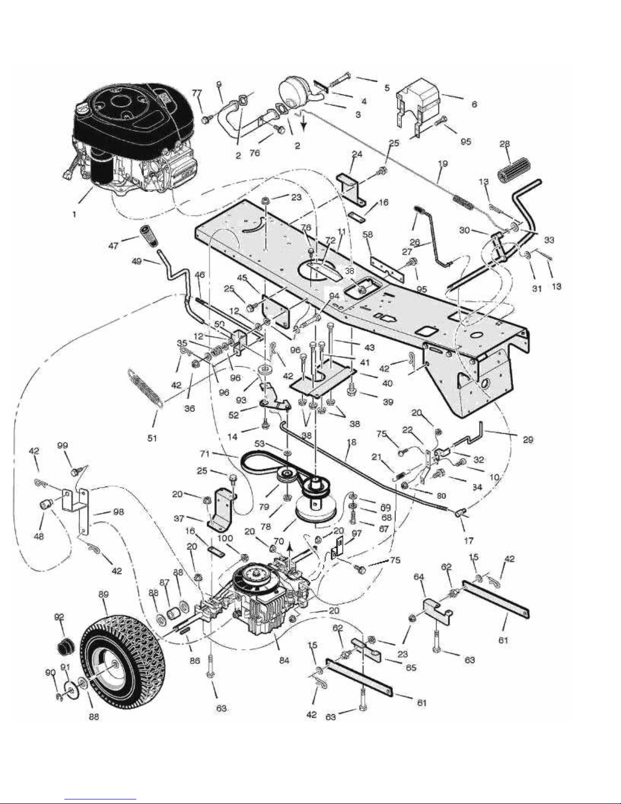
MODEL 536.270321
REPAIR PARTS
MOTION DRIVE
400150
44
Page 45

Model 536.270321 REPAIR PARTS
MOTION DRIVE
45
Key Key
No. Part No. Description No. Part No. Description
1 ------------ Engine 47 094497 Grip
2 091309 Gasket, Muffler 49 1401383 Lever, Shift
3 1401358 Muffler 50 1401340E701 Bracket, Pivot
4 092378 Lock, Muffler Screw 51 165x147 Spring, Variator Drive
5 01x134 Bolt, Hex 52 1741785 Arm, Idler
6 1401375 Shield, Heat 53 017x91 Washer
9 1401357 Tube, Exhaust 58 1401260E701 Plate, Reinforcement
10 0025x3 Bolt, Hex 61 1401031E701 Arm, Rear
11 1401371E701 Frame 62 094067 Pin, Threaded
12 17x217 Washer 63 01x156 Bolt, Hex
13 030x20 Pin, Cotter 64 1401301E701 Bracket, Left Rear Hanger
14 009x39 Bolt, Shoulder 65 1401302E701 Bracket, Right Rear Hanger
15 017x91 Washer 67 01x140 Bolt, Hex
16 1401334Z Plate, Transaxle 68 019x35 Lockwasher
17 094815 Nut, Adjusting 69 17x170 Washer
18 1401305 Rod, Clutch Hydro 70 1401308 Pulley, Stack
19 165x165 Spring, Brake 71 37x129 Belt, Drive
20 015x88 Nut 72 1401396Z Shield, Heat
21 BRS6 Spring, Roll Release 75 002x53 Bolt, Carriage
22 1741782 Bracket, Torque Strap 76 26x263 Screw
23 015x84 Nut 77 06x103 Screw
24 1401268E701 Bracket, Left Transaxle 78 015x98 Locknut
25 26x249 Screw 79 1401309 Pulley, Idler
26 1401337 Grip 80 15x143 Nut
27 1401112 Rod, Parking Brake 84 1741781 Transaxle
28 021544 Pedal 86 056534 Key Square
29 1401304Z Rod, Roll Release 87 1401103Z Spacer, Rear Wheel
30 1401127E701 Rod, Clutch/Brake 88 17x160 Washer
31 017x38 Washer 89 1401120 Wheel & Tire Assembly
32 1401303E701 Bracket, Roll Release -- ---------- Tire (ONLY)
33 017x53 Washer -- ---------- Tube (ONLY)
34 01x120 Screw 90 0011x3 E-Ring
35 164x39 Spring, Compression 91 17x195 Washer
36 15x119 Nut 92 094618 Hub Cap
37 1401042E701 Bracket, Right Transaxle 93 17x174 Washer
38 015x79 Nut 94 01x143 Bolt, Hex
39 0025x7 Screw 95 26x267 Screw
40 1401057E701 Plate, Belt Guide 96 17x104 Washer
41 1401105 Guide, Belt-Long 97 1742430 Bracket, Spring Extension
42 0031x4 Pin, Hair 98 1741784 Bracket, Shift Lever Weldment
43 1401104 Guide, Belt-Short 99 NB596 Bolt
45 1401032E701 Bracket, Lift Pivot 100 NB170 Nut, Serr Flange
46 1401307Z
1401380 Engine Plenum* 48 1401148 Nut, Adjusting
Rod, Shift Link
*Not Illustrated
400150
Page 46
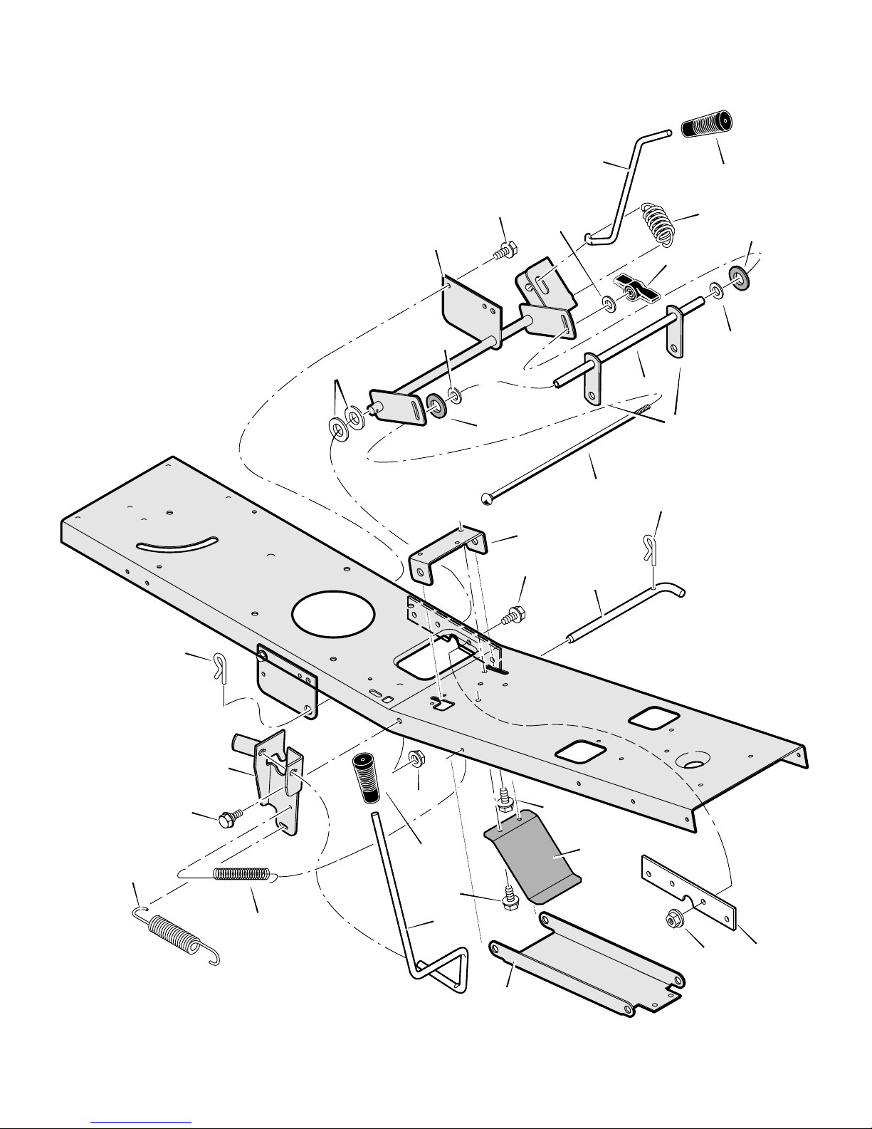
46
MOWER HOUSING SUSPENSION
1
2
3
4
5
13
5
6
14
5
15
4
9
10
11
12
9
24
25
26
27
19
13
20
21
22
23
18
7
8
31
17
30
400150
MODEL 536.270321 REPAIR PARTS
Page 47

47
MOWER HOUSING SUSPENSION
Key
No. Part No. Description
Key
No. Part No. Description
1 094497 Grip, Lift Lever
2 1401117 Lever, Lift
3 165x154 Spring, Extension
4 094137 Pad, Friction
5 017x45 Washer
6 095004 Wingnut
7 1401033E701 Link, Lift
8 1401096 Tube, Spacer
9 0031x4 Pin, Hair
10 002x93 Bolt, Carriage
11 1401030E701 Bracket, Front Hanger Pivot
12 1401118 Pin, Front Hanger
13 26x249 Screw
14 1401129E701 Arm Assembly, Lifter
15 17x206 Washer
17 015x79 Nut, Flange
18 015x84 Nut, Flange
19 1401147 Spring, Leaf
20 1401040E701 Hanger, Front
21 1401116 Lever, PTO
22 26x263 Screw
23 094498 Grip, PTO
24 1401369E701 Bracket, PTO
25 009x42 Bolt, Shoulder
26 165x157 Spring, Extension
27 165x92 Spring, Extension
30 1401260E701 Plate, Reinforcement
31 26x267 Screw
400150
MODEL 536.270321 REPAIR PARTS
Page 48
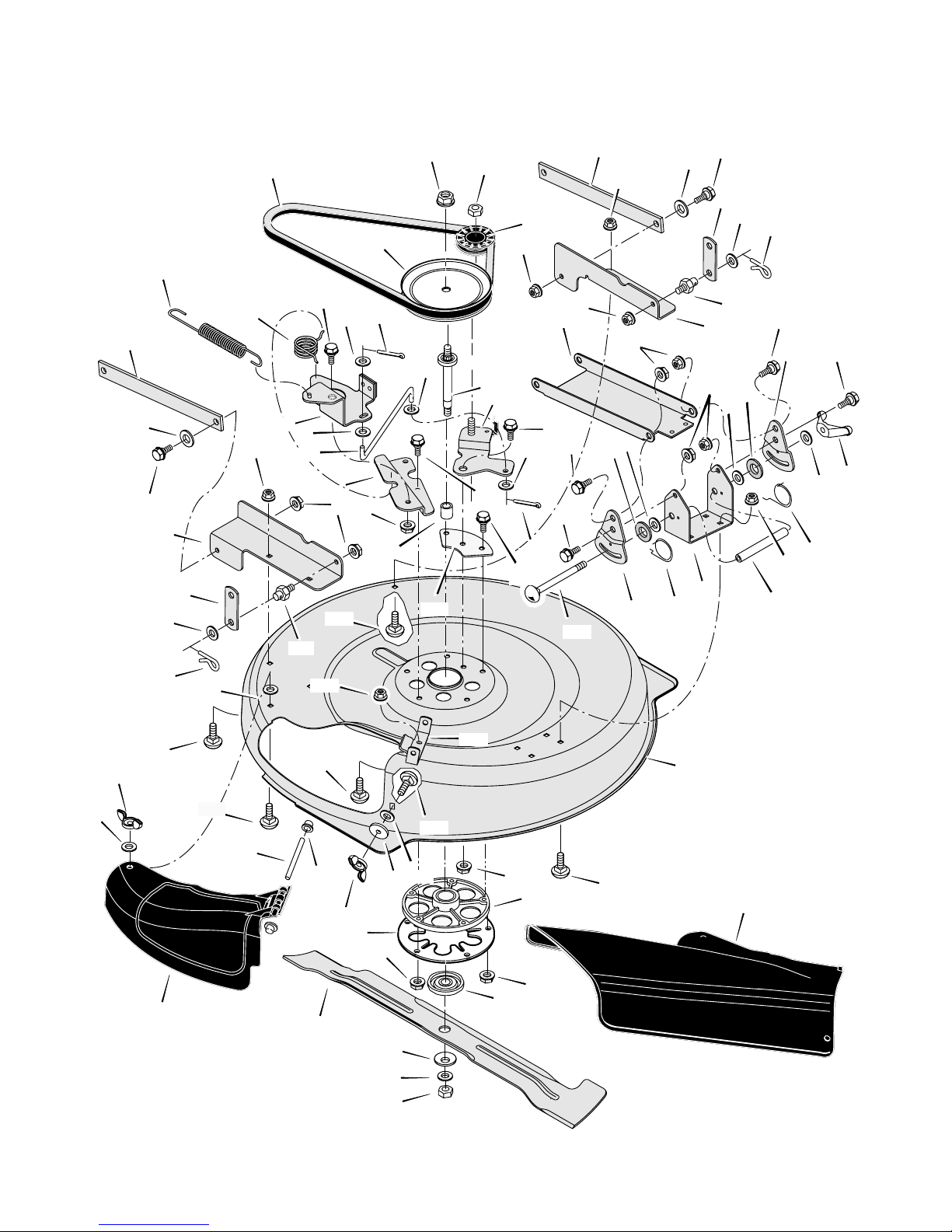
48
1
2
3
4
5
6
7
8
9
7
9
6
9
9
9
8
10
11
12
11
10
12
13
13
14
6
6
6
8
15
16
16
17
17
18
19
20
21
22
23
24
26
27
28
29
30
31
32
29
34
35
29
38
39
40
43
64
45
49
47
48
45
45
50
51
45
53
54
56
55
58
57
62
59
60
61
34
9
63
63
50
52
51
29
37
42
52
36
6
18
18
42
6
65
6
6
MOWER HOUSING
400150
MODEL 536.270321 REPAIR PARTS
Page 49

49
MOWER HOUSING
Key
No. Part No. Description
Key
No. Part No. Description
1 37x111 Belt, Blade Drive
2 1401092 Pulley, Input
3 15x140 Locknut
4 015x98 Nut, Flange
5 1401252 Pulley, Idler
6 015x84 Nut, Flange
7 1401031E701 Arm, Rear
8 015x79 Nut, Flange
9 009x58 Bolt, Shoulder
10 1401033E701 Link, Lift
11 17x102 Washer
12 0031x4 Pin, Hair
13 094067 Pin, Threaded Shoulder
14 1401047E701 Bracket, Left Rear
15 1401296E701 Bracket, Right Rear
16 1401038E701 Plate, Adjustment
17 094137 Pad, Friction
18 017x45 Washer
19 095004 Wingnut
20 166x43 Spring, Left Torsion
21 166x42 Spring, Right Torsion
22 1401095 Tube, Spacer
23 1401037E701 Bracket, Deck
24 1401040E701 Hanger, Front
26 1401065 Shaft, Splined
27 1401258E701 Arm Assembly , Idler
28 009x39 Bolt, Shoulder
29 017x47 Washer
30 165x157 Spring, Extension
31 166x46 Spring, Torsion
32 009x42 Bolt, Shoulder
34 030x20 Pin, Cotter
35 1401185E701 Arm Assembly, Brake
36 1401119 Link, Idler Arm
37 0025x7 Bolt
38 1401052E701 Bracket, Brake Mounting
39 1401094 Spacer, Jackshaft
40 1401259Z Plate, Idler Mounting
42 019x45 Washer
43 002x94 Bolt, Carraige
45 002x53 Bolt, Carriage
47 1401236E701 Housing, Blade
48 1401106E701 Hinge, Mulching Cover
49 015x88 Nut, Flange
50 028x76 Nut, Speed
51 014x86 Wingnut
52 002x74 Bolt, Carriage
53 091767Z Rod, Chute Deflector
54 028x23 Cap, Push
55 1401080 Cover, Mulch
56 094305 Mandrel Housing
57 1001035 Adapter, Blade
58 1401079E701 Blade
59 17x166 Washer, Cup
60 17x165 Washer
61 15x100 Nut, Blade Mount
62 1401081 Deflector, Chute
63 002x74 Bolt, Carriage
64 001x84 Bolt
65 1001952 Plate, Jackshaft Support
− − 7601035 Complete Mower Deck Assy.
400150
MODEL 536.270321 REPAIR PARTS
Page 50
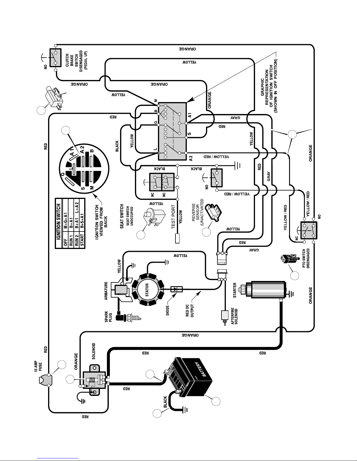
50
ELECTRICAL SYSTEM
94613
1001995
94159
24x37
24x24
24x24
MAIN HARNESS:
250x146
92739
94136
24273
1001575
OPTIONAL
3
5
9
2
4
1
6
7
8
10
11
400150
MODEL 536.270321 REPAIR PARTS
Page 51

51
ELECTRICAL SYSTEM
Key
No. Part No. Description
2 250x146 Harness, Chassis Wire
2 1001995 Switch, Ignition
327349 Key, Ignition
3 094136 Switch, Limit (PTO)
4 302031 Fuse
407078 Holder, Fuse
5 1002004 Solenoid
26x229 Screw, Mounting
15x116 Locknut
6 24x37 Cable, Battery Ground
26x229 Screw, Ground Cable
7 021075 Battery
690604 Cover, Battery Terminal
002x82 Bolt, Carriage
014x79 Wingnut
8 024273
Switch, Select Reverset
26x270 Screw, Mounting
9 094159 Switch, Seat Sensor
10 024x24 Cable
11 1001575 Switch, Clutch Brake
400150
MODEL 536.270321 REPAIR PARTS
Page 52

52
DECALS
Key
No. Part No. Description (Location) Qty.
− − 48x5212 Gas Gage (Dash −Left Side) 1
− − 44x7197 DEKA (Battery) 1
− − 44x7325 Warning (Seat Deck −Middle) 1
− − 48x5208 1−5 Height Adjust (Seat Deck −Left Side) 1
− − 48x746 NO STEP (Mower Deck − Left Side) 1
− − 48x5211 Clutch / Brake ( Footrest −Left Side) 1
− − 48x5707 Cut Finger (Mower Deck −Right Side) 1
− − 48x5915 Craftsman 13.5 (Hood −Right Side) 1
− − 48x5916 Craftsman 13.5 (Hood −Left Side) 1
− − 44x5214 Deck Level Position / ONLY (Seat Deck −Left Side) 1
− − 48x5057 Warning Load Limit (Rear) 1
− − 48x5182 Auto Disconnect 1
− − 48x5213 Craftsman Logo (Seat Deck Front) 2
− − 48x5209 Parking Brake Symbol (Console) 1
− − 48x5210 Throttle Control (Console) 1
− − 48x5205 Blade Engage / Disengage (Seat Deck −RIght Side) 1
− − 48x5887 Steering Wheel 1
− − 48x5204 Starting Instructions 1
− − 48x1019 13.5 HP I/C B&S (Engine) 1
−
− 48x6100 Decal, California Emissions 1
400150
MODEL 536.270321 REPAIR PARTS
Page 53

53
400150
Page 54
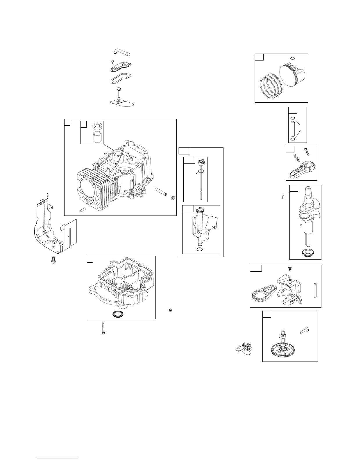
REPAIR PARTSBRIGGS & STRATTON ENGINE
54
MODEL 21B807-0326-E1
307
306
691
718
3
22
552
15
2
10
9
584
11
1263
1264
1
12
20
4
26
27
27
32
24
842
524
847
523
525
741
146
29
28
25
16
43
1270
758
759
757
45
46
400150
Page 55

REPAIR PARTSBRIGGS & STRATTON ENGINE
55
MODEL 21B807-0326-E1
1 697377 Cylinder Assembly
2 399265 Kit−Bushing/Seal
(Magneto Side)
3 K391086s Seal−Oil
(Magneto Side)
4 697106 Sump−Engine
9 K697109 Gasket−Breather
10 697157 Screw
(Breather Assembly)
11 697113 Tube−Breather
12 K697110 Gasket−Crankcase
15 690946 Plug−Oil Drain
16 697390 Crankshaft
20 K690947 Seal−Oil
(PTO Side)
22 692125 Screw
(Crankcase Cover/
Sump)
24 222698s Key−Flywheel
25 792305 Piston Assembly
(Standard)
−−−−−−− Note −−−−−
792642 Piston Assembly
(.020” Oversize)
26 792306 Ring Set
(Standard)
−−−−−−− Note −−−−−
792643 Ring Set
(.020” Oversize)
27 698469 Lock−Piston Pin
28 697099 Pin−Piston
29 791633 Rod−Connecting
(Standard)
32 791118 Screw
(Connecting Rod)
43 691968 Slinger−Governor/Oil
45 690564 Tappet−Valve
46 790400 Camshaft
146 691639 Key
−Timing
306 697359 Shield−Cylinder
307 691003 Screw
(Cylinder Shield)
523 699908 Dipstick
524 K691032 Seal−Dipstick Tube
525 697184 Dipstick
552 697144 Bushing−Governor
Crank
584 697112 Cover−Breather
Passage
691 K692407 Seal−Governor Shaft
718 690959 Pin−Locating
741 697128 Gear−Timing
842 K691031 Seal−O Ring
(Dipstick Tube)
847 790442 Dipstick/Tube Assembly
757 697607 Link−Counterweight
758 697391 Counterweight
759 697392 Pin−Counterweight
1263 697124 Reed−Breather
1264 697104 Screw
(Breather Reed)
1270 697156 Plug−AVS Counterweight
REF. PART REF. PART REF. PART
NO. NO. DESCRIPTION NO. NO. DESCRIPTION NO. NO. DESCRIPTION
400150
Page 56
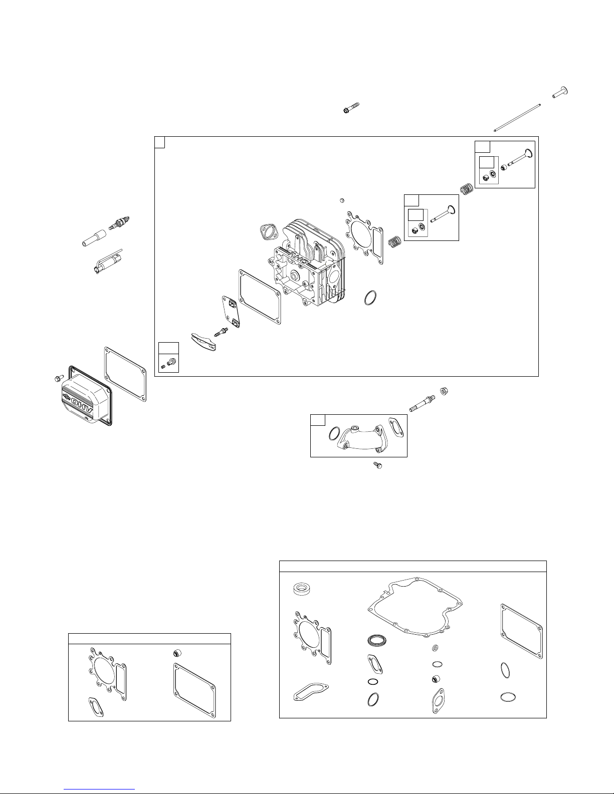
REPAIR PARTSBRIGGS & STRATTON ENGINE
56
MODEL 21B807-0326-E1
42
51
53
54
654
617
635
13
617
830
1034
1022
883
7
238
36
868
35
1022
1023
914
1022
868
51
1095 VALVE GASKET SET
7
383
5
192
1022
12
9
7
3
358 ENGINE GASKET SET
868
691
524
51
20
617
883
1266
842
34
50
1029
45
1026
1266A
42
42
33
337
400150
Page 57

REPAIR PARTSBRIGGS & STRATTON ENGINE
57
MODEL 21B807-0326-E1
3 K391086s Seal−Oil
(Magneto Side)
5 697396 Head−Cylinder
7∅K273280s Gasket−Cylinder Head
9 K697109 Gasket−Breather
12 K697110 Gasket−Crankcase
13 690360 Screw
(Cylinder Head)
20 K690947 Seal−Oil
(PTO Side)
33 695760 Valve−Exhaust
34 695761 Valve−Intake
35 691279 Spring−Valve
(Intake)
36 691279 Spring−Valve
(Exhaust)
42 499586 Keeper−Valve
45 690564 Tappet−Valve
50 697361 Manifold−Intake
51∅DK
z692137 Gasket−Intake
53 690227 Stud
(Carburetor)
54 691148 Screw
(Intake Manifold)
192 691986 Adjuster−Rocker Arm
238 691843 Cap−Valve
337 491055s Plug−Spark
358 697151 Gasket Set−Engine
383 89838s Wrench−Spark Plug
524 K691032 Seal−Dipstick Tube
617 KD692138 Seal−O Ring
(Intake Manifold)
635 691909 Boot−Spark Plug
654 690958 Nut
(Carburetor)
691 K692407 Seal−Governor Shaft
830 691095 Stud−Rocker Arm
842 K691031 Seal−O Ring
(Dipstick Tube)
868 ∅K690968 Seal−Valve
883 K692236 Gasket−Exhaust
914 691108 Screw
(Rocker Cover)
1022∅K272475s Gasket−Rocker Cover
1023 791079 Cover−Rocker
1026 697395 Rod−Push
(Exhaust)
−−−−−−− Note
−−−−−
697394 Rod−Push
(Intake)
1029 691751 Arm−Rocker
1034 690822 Guide−Push Rod
1095 691581 Gasket Set−Valve
1266 KD691917 Seal−O Ring
(Intake Elbow)
1266A KD697123 Seal−O Ring
(Intake Elbow)
REF. PART REF. PART REF. PART
NO. NO. DESCRIPTION NO. NO. DESCRIPTION NO. NO. DESCRIPTION
400150
Page 58
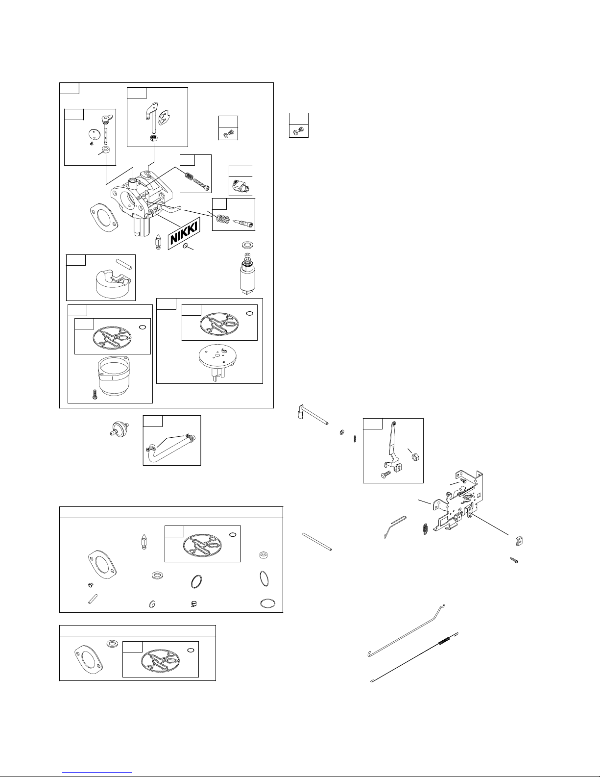
REPAIR PARTSBRIGGS & STRATTON ENGINE
58
MODEL 21B807-0326-E1
977 CARBURETOR GASKET SET
121 CARBURETOR OVERHAUL KIT
95
104
127
617
634
51
51
1266
1266A
987
1127
104
105
51
634
987
95
130
127
108
117
118
276
135
947
1091
240
187
601
216
202
232
265
209
222
188
616
404
614
562
505
227
521
267
125
131
141
133
975
98
94
276
137
137
137
137
276
105
400150
Page 59

REPAIR PARTSBRIGGS & STRATTON ENGINE
59
MODEL 21B807-0326-E1
51∅DKz692137 Gasket−Intake
94 695425 Kit−Idle Mixture
95 D690718 Screw
(Throttle Valve)
98 695408 Kit−Idle Speed
104 D694918 Pin−Float Hinge
105 D696136 Valve−Float Needle
108 697723 Valve−Choke
117 699897 Jet−Main
(Standard)
118 699898 Jet−Main
(High Altitude)
121 698787 Kit−Carburetor Overhaul
125 699916 Carburetor
127 D690727 Plug−Welch
130 698774 Valve−Throttle
131 698776 Kit−Throttle Shaft
133 694914 Float−Carburetor
135 698780 Tube−Fuel Transfer
137 D
z698781 Gasket−Float Bowl
141 698778 Kit−Choke Shaft
187 791805 Line−Fuel
(Formed)
188 691693 Screw
(Control Bracket)
202 691841 Link−Mechanical
Governor
209 792602 Spring−Governor
216 691840 Link−Choke
222 694042 Bracket−Control
227 691374 Lever−Governor Control
232 691842 Spring−Governor Link
240 394358s Filter−Fuel
265 691024 Clamp−Casing
267 695134 Screw
(Casing Clamp)
276 D
z695410 Washer−Sealing
404 691691 Washer
(Governor Crank)
505 691251 Nut
(Governor Control Lever)
521 690581 Shield−Cable
562 691119 Bolt
(Governor Control Lever)
601 791850 Clamp−Hose
614 691620 Pin−Cotter
616 692012 Crank−Governor
617 D692138 Seal−O Ring
(Intake Manifold)
634 KD698779 Spring/Seal Assembly
(Choke Shaft)
947 699915 Solenoid−Fuel
975 699502 Bowl−Float
977 790032 Gasket Set−Carburetor
987 D698777 Seal−Throttle Shaft
1091 691333 Cap−Limiter
1127 695407 Screw
(Float Bowl)
1266 KD691917 Seal−O Ring
(Intake Elbow)
1266A KD697123 Seal−O Ring
(Intake Elbow)
REF. PART REF. PART REF. PART
NO. NO. DESCRIPTION NO. NO. DESCRIPTION NO. NO. DESCRIPTION
400150
Page 60
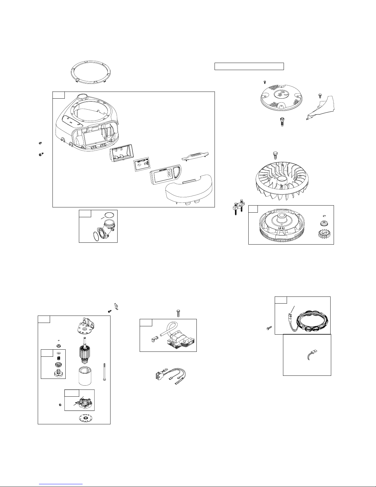
REPAIR PARTSBRIGGS & STRATTON ENGINE
60
MODEL 21B807-0326-E1
445
1267
967
305
305A
643
968
304
1040
1266A
1266
431
1036 EMISSION LABEL
783
1051
1070
363
73
74
1005
1044
37
78
23
697
729
802
579
1051
310
803
544
801
311
797
513
783
309
510
1090
851
334
333
789
1119
878
877
474
400150
Page 61

REPAIR PARTSBRIGGS & STRATTON ENGINE
61
MODEL 21B807-0326-E1
23 792497 Flywheel
37 697352 Guard−Flywheel
73 697133 Screen−Rotating
74 697897 Screw
(Rotating Screen)
78 691003 Screw
(Flywheel Guard)
304 699085 Housing−Blower
305 697102 Screw
(Blower Housing)
305A 697103 Screw
(Blower Housing)
309 693551 Motor−Starter
310 690323 Screw
(Starter Motor)
311 497608 Brush Set
333 492341 Armature−Magneto
334 691061 Screw
(Magneto Armature)
363 19203 Puller−Flywheel
431 697122 Elbow−Intake
445 698413 Filter−Air Cleaner
Cartridge
474 696459 Alternator
510 693699 Drive−Starter
513 692024 Clutch−Drive
544 692034 Armature−Starter
579 691029 Nut
(Starter Cable)
643 697155 Retainer−Air Filter
697 690372 Screw
(Drive Cap)
729 691224 Clip−Wire
783 693713 Gear−Pinion
789 698329 Harness−Wiring
797 693167 Nut
(Brush Retainer)
801 691283 Cap−Drive
802 691286 Cap−
End
803 693757 Housing−Starter
851 692424 Terminal−Spark Plug
877 393456 Wire/Connector−Alterna-
tor
878 691237 Harness−Alterenator
967 697292 Filter−Pre Cleaner
968 697420 Cover−Air Cleaner
1005 699044 Fan−Flywheel
1036 791931 Label−Emissions
1040 698368 Plate−Trim
1044 698139 Screw
(Flywheel)
1051 691265 Ring−Retaining
1070 690372 Screw
(Flywheel Fan)
1090 691293 Retainer−Brush
1119 691183 Screw
(Alternator)
1266 KD691917 Seal−O Ring
(Intake Elbow)
1266A KD697123 Seal−O Ring
(Intake Elbow)
1267 697419 Latch−Blower Housing
REF. PART REF. PART REF. PART
NO. NO. DESCRIPTION NO. NO. DESCRIPTION NO. NO. DESCRIPTION
400150
Page 62

62
Page 63

63
Page 64

INDEX
64
F−050615L
A
Adjustments
Blade Drive Lever, 29
Clutch, 33
Mower Housing, Level, 28
Air Screen, 26
Attachments, 11
Automatic Drive Disconnect,
Operation, 9, 14
B
Battery
Charge, 24
Check, 8
Clean, 24
Install, 8
Removal, 24
Storage, 35
Belt
Drive Belt, Adjust, 33
Motion Drive
Adjust, 33
Replace, 31
Mower Drive
Adjust, 29
Replace, 32
Blade
Inspect, 23
Remove And Install, 23
Sharpen, 23
Blade Drive Lever, Adjust, 29
Blade Rotation Control,
Operation, 13
C
Clutch
Adjust, 33
Check, 33
Clutch / Brake Pedal, Location, 10
Controls, Location, 10
Cutting Height
Adjust, 28
Change, 13
D
Drive Belt, Adjust, 33
E
Electrical Safety System, 11
Engine
Cooling System, 26
Fuel, 9, 18
Lubrication, 26
Muffler, 26
Oil, 9, 18, 26
Preparation, 9
Spark Arrester, 9, 26
Starting, 19
Storage, 35
Throttle Control, 12
F
Filter, Air, 27
Fuel, Type, 18
Fuse, 35
I
Ignition Key Switch, Operation, 11
Ignition Switch, Location, 10
L
Lift Lever
Location, 10
Operation, 13
Lubrication
Engine, 26
Mower, 25
M
Maintenance
Battery
Charge, 24
Clean, 24
Belt
Motion Drive, 31
Mower Drive, 32
Blade, 23
Clutch, 33
Filter, Air, 27
Fuse, 35
Install, Wheels, 34
Lubrication, 25
Mower Housing
Clean, 35
Install, 30
Level, 28
Remove, 30
Muffler, 26
Spark Plug, 27
Maintenance Chart, 22
Motion Drive Belt
Adjust, 33
Replace, 31
Mower Drive Belt
Adjust, 29
Replace, 32
Mower Housing
Clean, 35
Cutting Height, 13
Install, 30
Level Adjustment, 28
Operation, 20
Remove, 30
Muffler, 26
Spark Arrester, 26
Mulcher, Operation, 21
Mulcher Cover, Remove, 17
O
Oil
Change, 26
Check, 18, 26
Type, 18
Operation
Attachments, 11
Automatic Drive Disconnect, 9, 14
Blade Rotation Control, 13
Clutch / Brake Pedal, 10
Ignition Key Switch, 11
Ignition Switch, 10
Lift Lever, 10, 13
Location Of Controls, 10
Mower Housing, 20
Mowing And Bagging, 21
Mulching, 21
Operate On Hills, 20
Parking Brake, 10, 12
Speed Control Lever, 10
Speed Control Lever, 15
Start The Engine, 19
Stop The Unit, 12
Throttle Control, 10, 12
Transport, 16
P
Parking Brake
Location, 10
Operation, 12
S
Safety Rules, American National
Standard Institute, 4–5
Service And Adjustment,
Blade Drive Lever, 29
Side Discharge Attachment,
Install, 17
Slope Guide, 39
Spark Arrester, 9, 26
Spark Plug, 27
Speed Control Lever
Location, 10
Operation, 15
Speed Control Leverl, Adjust, 33
T
Throttle Control
Location, 10
Operation, 12
Tire Pressure, 9, 22
Trouble Shooting Chart, 36
W
Warranty, 2
Wheel Alignment, 35
Page 65

65
Tractor cortacésped con motor situado detrás del asiento
PRECAUCIÓN: Antes de usar este producto, lea este manual y siga
todas las reglas de seguridad e instrucciones de operación.
CONTENIDO
PIEZAS 40. . . . . . . . . . . . . . . . . . . . . . . . . . . . . . . . . . . . . . .
GARANTÍA 65. . . . . . . . . . . . . . . . . . . . . . . . . . . . . . . . . . .
ESPECIFICACIONES DEL PRODUCTO 66. . . . . . . . . .
REGLAS DE SEGURIDAD 68. . . . . . . . . . . . . . . . . . . . . .
PREPARACIÓN 72. . . . . . . . . . . . . . . . . . . . . . . . . . . . . . .
OPERACIÓN 75. . . . . . . . . . . . . . . . . . . . . . . . . . . . . . . . . .
MANTENIMIENTO 87. . . . . . . . . . . . . . . . . . . . . . . . . . . . .
SERVICIO Y AJUSTE 93. . . . . . . . . . . . . . . . . . . . . . . . . .
TABLA DE LOCALIZACIÓN DE AVERÍAS 101. . . . . . . .
GUÍA DE INCLINACIÓN 106. . . . . . . . . . . . . . . . . . . . . . . .
GARANTÍA LIMITADA EN CRAFTSMAN TRACTORES
Este Tractor Craftsman está garantizado por dos (2) años a partir de la fecha de compra, siempre y cuando se le haya
mantenido lubricado y afinado de acuerdo a las instrucciones especificadas en el Manual del Usuario. Sears reparará o
reemplazará, sin costo alguno, cualquier parte del equipo que resulte defectuosa, ya sea en material o mano de obra, de
acuerdo a las especificaciones de cobertura listadas a continuación.
Por dos años completos, Sears proveerá mano de obra sin costo para estas partes garantizadas. Durante los primeros 30
días después de la compra, contará con servicio a domicilio gratuito para las condiciones cubiertas por esta garantía. (Favor
de leer las exclusiones a continuación).
Para su conveniencia, el servicio de garantía A DOMICILIO estará disponible todavía después de los primeros 30 días de la
fecha de compra, pero se aplicará a este servicio un cargo por el viaje. Este cargo no será aplicado si lleva el Craftsman
producto a un Centro de Servicio Sears autorizado. Para localizar el Centro de Servicio Sears autorizado, más cercano a usted,
favor de llamar al 1−800−4−MY−HOME®. Esta garantía aplica solamente mientras el producto se encuentra dentro de
Estados Unidos.
Esta garantía no cubre:
• Partes de duración limitada que se desgastan con el uso normal, incluyendo pero sin limitarse a cuchillas, bujías, filtros
de aire, correas y filtros de aceite.
• Servicio de Mantenimiento Estándar, cambios de aceites o afinamientos.
• Remplazo o reparación de neumáticos debido a pinchazos por objetos externos, tales como clavos, espinas, tocones o
vidrio.
• Reparaciones necesarias a causa de abuso por parte del operador, incluyendo pero sin limitarse a, daños debidos al
remolque de objetos que sobrepasan la capacidad del tractor, golpes de la unidad contra objetos que doblen el chasis
o el cigüeñal, o daño debido a la velocidad excesiva a que se somete al motor.
• Reparaciones necesarias a causa de negligencia por parte del operador, incluyendo pero sin limitarse a, daño eléctrico
y mecánico debidos al almacenamiento inadecuado de la unidad, daño por no usar el grado correcto de aceite de motor
y en la cantidad recomendada, daño por no mantener la plataforma limpia de basuras inflamables, o por no mantener el
equipo de acuerdo a las instrucciones que aparecen en el manual del propietario.
• Limpieza o reparaciones al motor (sistema de combustible) por usar combustible contaminado u oxidado (viejo).
Generalmente, el combustible debe usarse dentro de 30 días de la fecha de compra.
• Deterioro y desgaste normal del acabado exterior, o reemplazo de las etiquetas del producto.
• Tractor que sea utilizado con fines comerciales o de alquiler.
GARANTÍA LIMITADA PARA BATERÍA
Si en el plazo de noventa (90) días a partir de la fecha de compra, cualquier batería que esté incluida con este tractor , resultara
defectuosa sea en el material o mano de obra y, nuestras pruebas determinen que la batería no mantiene la carga, Sears remplazará la batería sin costo para usted. Durante los primeros 30 días a partir de la fecha de compra, la batería podrá ser reemplazada a domicilio, sin cargo para usted. Para su conveniencia, el servicio de garantía A DOMICILIO estará disponible todavía
después de los primeros 30 de la fecha de compra, pero se aplicará a este servicio un cargo por el viaje. Este cargo no será
aplicado si lleva el producto a un Centro de Servicio Sears autorizado. Para localizar el Centro de Servicio Sears autorizado,
más cercano a usted, favor de llamar al 1−800−4−MY−HOME®. Esta garantía aplica solamente mientras el producto se encuentre dentro de Estados Unidos. Esta garantía le otorga derechos legales específicos, además, usted puede tener otros
derechos legales que varían según el estado donde resida.
Sears, Roebuck and Co., Dept. 817WA, Hoffman Estates, IL. 60179.
400150
Modelo 536.270321
Page 66
66
Felicidades por su compra de este Tractor cortacésped con
motor situado detrás del asiento de Craftsman. Su unidad ha sido
diseñada y fabricada para darle los mejores resultados en lo que
se refiere a confiabilidad y desempeño.
Si encuentra algún problema en la unidad que usted no pueda
solucionar, consulte con el Centro de Servicio Sears más
cercano a usted. Nuestros técnicos capacitados disponen de las
herramientas necesarias para reparar o dar servicio a esta
unidad.
Favor de leer y guardar este manual. Las instrucciones le
permitirán ensamblar y mantener su unidad de la manera
apropiada. Siga siempre las “Reglas de seguridad”.
ESPECIFICACIONES DEL PRODUCTO
Motor 13,5 HP.. . . . . . . . . . . . . . . . . . .
Diámetro interior 3,44 pulg. (87,31 mm). . . . . .
Carrera 3,06 pulg. (77,78 mm). . . . . . . . . . . . . . .
Cilindrada 28,42 pulg. cúb. (466 cc). . . . . . . . . . . . .
Entrehierro de inducido 0,010-0,014 pulg. (0,25-0,36 mm)
Juego de válvula con los resortes de válvula instalados y
el pistón a 0,25 pulg. (6 mm) más allá del punto muerto
superior (verificar con un motor frío)
Admisión 0,003-0,005 pulg. (0,08-0,13 mm). . . . . . . . . . . . .
Escape 0,005-0,007 pulg. (0,13-0,18 mm). . . . . . . . . . . . . . .
Sistema de Carga 3 amperios a 3600 rpm. . . . . . . .
Tamaño del Tanque de
Combustible 1,1 galón. . . . . . . . . .
Tipo de Combustible Regular, sin plomo. . . . .
Capacidad de Aceite 48 onzas (3 pintas). . . . . .
Tipo de Aceite Arriba de 32 grados SAE 30. . . . . . . . . . .
Debajo de 32 grados SAE 5W30. . . . . . . . . . . . . . . . . . . . . . . . . .
Bujía (Separación 0,030”) Champion RJ4C.
Presión de Aire de Neumáticos Delantera 22 psi (vea el costado .
del neumático). . . . . . . . . . . . . . . . . . . . . . . . . .
Presión de Aire de Neumáticos Trasera 14 psi (vea el costado .
del neumático). . . . . . . . . . . . . . . . . . . . . . . . . .
Sistema de propulsión Hidrostático. . . . . . .
Velocidad de Vehículo 5,0 mph de avance. . . .
2,5 mph de marcha atrás. . . . . . . . . . . . . . . . . . . . . . . . . .
Asiento con Inclinación Acceso al motor y a la batería.. . .
Cárter de la Cortadora Suspensión no restringida, una . . . .
cuchilla.
Altura de Corte 6 posiciones de 1
1
/2 a 4 pulgadas.. . . . . . . . . . .
Par de Torsión de
Tuerca de Cuchilla 30 pies−libra (ft−lbs). . . . .
Clasificación de potencia: La clasificación de potencia para un
modelo de motor en particular se desarrolla inicialmente comenzando con el código J1940 de SAE (Sociedad de Ingenieros Automotrices) (Procedimiento de Clasificación de Potencia y
Torsión de Motores Pequeños) (Revisión 2002-05). Dado el amplio conjunto de productos en los cuales son instalados nuestros
motores, y la variedad de emisiones ambientales aplicables al
operar el equipo, puede que el motor que usted haya comprado
no desarrolle la potencia nominal cuando sea usado en una parte
del equipo acoplado (potencia real “en el-sitio”). Esta diferencia
se debe a una variedad de factores incluyendo, pero no limitándose a, lo siguiente: diferencias en altitud, temperatura, presión
barométrica, humedad, combustible, lubricación del motor, máxima velocidad regulada del motor, el motor particular a la variabilidad del motor, diseño de la parte en particular del equipo
acoplado, la manera en la cual es operado el motor, el despegue
del motor para reducir la fricción y para limpiar las cámaras de
combustión, los ajustes a las válvulas y al carburador, y otra variedad de factores. Esta clasificación de potencia puede también
ser ajustada basándose en comparaciones a otros motores semejantes utilizados en aplicaciones similares, y por lo tanto no se
igualarán necesariamente los valores derivados usando los códigos anteriores.
NOTA: Es probable que la potencia continua sea menor debido a limitaciones de operación y a factores ambientales.
Tractor cortacésped con motor
situado detrás del asiento
Anote en los espacios correspondientes, el número de serie
y la fecha de compra de la unidad.
Los números de modelo y serie se encuentran en la etiqueta fijada a la unidad.
Número de serie:
Fecha de compra:
Guarde esta información para referencia futura.
ACUERDO DE PROTECCIÓN PARA
REPARACIONES
Existe un Acuerdo de Protección para Reparaciones para esta
unidad. Para obtener más información, consulte en la tienda Sears
más cercana a usted.
Los gases de escape del motor, así como varios
de sus constituyentes, y algunos componentes
de este vehículo contienen o emiten sustancias
químicas reconocidas por el Estado de
California como carcinógenas, también pueden
producir defectos congénitos u otros daños al
sistema reproductivo.
Los bornes, terminales y accesorios relacionados con la batería contienen plomo y compuestos del plomo, sustancias químicas que el Estado de California reconoce como carcinógenas,
además estas sustancias pueden producir daños congénitos a los bebés u otros daños al sistema reproductivo humano. DEBE LAVARSE
LAS MANOS DESPUÉS DE MANIPULAR ESTOS
COMPONENTES.
270321
400150
Número de modelo: 536.
Page 67

67
NOTA: Esta unidad está equipada con un motor de combustión
interna y no debe ser utilizada sobre o cerca de terrenos no
cultivados cubiertos de bosque, maleza o césped a menos que el
sistema de escape del motor esté equipado con un parachispas
que cumpla con las leyes locales o estatales aplicables (si
existen). Si se utiliza un parachispas, el operador debe
mantenerlo en buenas condiciones de funcionamiento.
En el estado de California, estas condiciones son requeridas por la
ley (Sección 4442 del Código de Recursos Públicos de California).
Otros estados pueden tener leyes semejantes. Las leyes federales
son aplicables en terrenos federales. Vaya a un Centro de Servicio
Sears para obtener un parachispas para el tubo de escape.
En algunos lugares, las leyes locales requieren el uso de una
bujía de resistencia para controlar las señales de encendido.
Consulte en un Centro de Servicio Sears para conseguir la bujía
de resistencia para el motor.
NOTA: Es probable que la potencia continua sea menor debido a limitaciones de operación y a factores ambientales.
En el estado de California, los Modelos de motores de la Serie
280000 están certificados por la Junta de recursos del aire de
California para cumplir con los estándares de emisiones de 125
horas. Dicha certificación no ofrece al comprador, propietario u
operador de este motor ninguna garantía adicional con respecto
al rendimiento o vida útil de este motor. Este motor está garantizado únicamente de acuerdo a las garantías del producto y de
emisiones indicadas en otras secciones de este manual.
400150
Page 68

REGLAS DE SEGURIDAD
68
Prácticas de operación segura para vehículos autoportados
Se usa el símbolo de seguridad para identificar información de seguridad acerca de peligros que pudieran resultar en lesiones personales. Se usa una palabra de aviso (PELIGRO, ADVERTENCIA o PRECAUCIÓN) con el
símbolo de alerta para indicar la posibilidad y la posible gravedad de una lesión. También, se puede usar un símbolo
de peligro para representar el tipo de peligro.
PELIGRO indica un peligro que, si no se evita, va a resultar en muerte o lesión grave.
ADVERTENCIA indica un peligro que, si no se evita, puede resultar en muerte o lesión grave.
PRECAUCIÓN indica un peligro que, si no se evita, podría resultar en una lesión leve o moderada.
PRECAUCIÓN cuando se usa sin el símbolo de alerta, indica una situación que podría resultar en daño al motor.
PRECAUCION: Esta máquina cortadora es capaz de amputar manos y pies y de lanzar objetos con mucha fuerza. No
respetar las instrucciones de seguridad a continuación podría resultar en lesiones graves o la muerte del operador o
de espectadores.
I. OPERACIÓN GENERAL:
1. Antes de comenzar el trabajo, lea, entienda y siga todas las
instrucciones que aparecen en el Manual de Instrucciones,
en la máquina, en el motor y en cualquiera de los aditamentos.
2. Sólo permita que adultos responsables, familiarizados con
las instrucciones, utilicen la máquina.
3. Despeje el área de objetos tales como piedras, juguetes,
cables, etc., que podrían ser lanzados con fuerza por la cuchilla.
4. Antes de comenzar a cortar el césped, asegúrese de que no
haya ninguna persona en el área. Si alguien entra en el
área, pare de inmediato la máquina.
5. Nunca lleve pasajeros.
6. Antes de retroceder, desconecte la alimentación al cortacés-
ped o a cualquier aditamento que tenga instalado. No corte
el césped en reversa a menos que esto sea absolutamente
necesario. Siempre mire hacia abajo y hacia atrás antes de
retroceder y mientras retrocede.
7. Esté atento a la dirección de descarga de la hierba cortada.
No dirija la descarga hacia personas o hacia lugares donde
pudiera haber gente. No opere la unidad sin tener instalado
el recolector de hierba o el dispositivo de seguridad.
8. Aminore la velocidad antes de dar la vuelta.
9. Nunca deje una máquina desatendida mientras el motor está
en marcha. Siempre desembrague la cuchilla(s), enganche
el freno de mano, pare el motor y retire la llave antes de bajarse.
10. Desconecte la alimentación a los aditamentos cuando no los
esté utilizando o cuando transporte la unidad. Desembrague
la cuchilla(s) cuando no esté cortando el césped.
11. Pare el motor antes de desmontar el recolector de hierba o
para desobtruir el conducto de descarga.
12. Corte el césped a la luz del día o con buena luz artificial.
13. No opere la máquina si está bajo los efectos del alcohol o de
drogas, o si está muy cansado.
14. Esté atento al tráfico cuando opere la máquina cerca de ca-
minos o si debe cruzarlos.
15. Si usa un remolque o camioneta para transportar la unidad,
tenga mucho cuidado al cargar o descargar la unidad del
vehículo.
16. Desenganche todos los embragues de los aditamentos y
coloque la palanca de cambios en la posición neutro antes
de arrancar el motor.
17. Siempre use gafas de protección u algún tipo de protector
para los ojos cuando utilice la unidad, de esta manera protegerá sus ojos de objetos que pudieran ser lanzados por la
máquina. Este tipo de protección ocular también debe usarlo cuando necesite hacer ajustes o reparaciones a la máquina.
18. Tenga mucho cuidado cuando deba remolcar cargas o cuando utilice equipos pesados.
a. Utilice únicamente barras de enganche con puntos de
remolque aprobados.
b. Limite las cargas a aquellas que usted pueda controlar
con seguridad.
c. No gire el volante bruscamente. Tenga cuidado al retroceder.
d. Utilice contrapesos o pesos en las ruedas cuando esto
sea recomendado en el Manual de Instrucciones.
19. No opere esta máquina si está tomando drogas u otras medicinas que pudieran causar somnolencia o que pudieran
afectar su habilidad para operar esta máquina.
20. No opere esta máquina si su estado emocional o físico no le
permite operarla con seguridad.
21. Los datos recopilados indican que los operadores de 60
años o más, sufren un mayor número de accidentes y lesiones relacionados con el manejo de máquinas cortacésped.
Estos operadores deben evaluar sus habilidades para manejar de manera segura un tractor cortacésped y evitar así lesiones graves que pudieran sufrir ellos u otras personas que
se encuentren presentes.
II. OPERACIÓN EN CUESTAS:
Las cuestas y los terrenos accidentados son factores principales
que se relacionan a accidentes causados por pérdidas de control
o por vuelcos de la unidad y que pueden resultar en lesiones
graves o muerte. TODAS las cuestas requieren que se tomen
precauciones adicionales. Si no puede subir la cuesta usando el
cambio de marcha atrás, o si se siente incómodo en la cuesta,
no la corte. Consulte la “Guía de evaluación de cuestas”. Para
obtener mayor información al respecto, consulte esta guía que
aparece al final de este manual.
400150
Page 69

REGLAS DE SEGURIDAD
69
RECOMENDACIONES
1. En las cuestas, corte el césped verticalmente (hacia arriba y
hacia abajo), y no en línea perpendicular (de lado a lado).
2. Quite todo obstáculo tal como piedras, ramas, etc.
3. Tenga cuidado con los hoyos, baches o resaltos. El terreno
disparejo puede hacer que la máquina se vuelque. “La hierba muy alta puede esconder obstáculos”.
4. Maneje la unidad a baja velocidad. Seleccione una velocidad suficientemente baja para que no tenga que parar o
cambiar de velocidad mientras está en la cuesta.
5. Respete y siga las recomendaciones del fabricante acerca
de pesos para las ruedas o contrapesos para mejorar la estabilidad.
6. Tenga mucho cuidado cuando utilice el recolector de hierba
u otros aditamentos, estos afectan la estabilidad de la máquina.
7. Procure que todos los movimientos en las cuestas sean len-
tos y graduales. No haga cambios bruscos de velocidad o
de dirección.
8. Evite tener que arrancar el motor o pararlo en una cuesta.
Si los neumáticos pierden tracción, desembrague la cuchilla(s) y continúe despacio directamente hacia el pie de la
cuesta.
PRECAUCIONES
1. No gire en las cuestas a menos que sea absolutamente necesario, si debe hacerlo, gire lenta y gradualmente cuesta
abajo, si es posible.
2. No corte el césped cerca de precipicios, zanjas o terraplenes. Una rueda sobre un borde o el desprendimiento de un
borde podría causar un vuelco inesperado provocando lesiones o la muerte.
3. No corte el césped si está mojado. La reducida tracción
puede hacer que la máquina resbale.
4. No trate de estabilizar la máquina bajando su pie al suelo.
5. No utilice el recolector de hierba ni otro accesorio de remolque en cuestas empinadas (de más de 10 grados).
III. NIÑOS:
Pueden ocurrir accidentes trágicos si el operador no está alerta a
la presencia de niños. A muchos niños les atraen las cortadoras
autoportadas. NUNCA suponga que los niños permanecerán en
el último lugar donde los vió.
1. Mantenga a los niños fuera del área de trabajo y bajo el cuidado de un adulto que no sea el operador.
2. Manténgase alerta y pare el motor si entran niños al área.
3. Antes y mientras retrocede, mire hacia atrás y hacia abajo
por si hay niños.
4. Nunca permita que niños u otras personas vayan como “pasajeros” en el cortacésped, ni siquiera cuando la cuchilla(s)
no esté puesta. Ellos pueden caerse , lesionarse gravemente o pueden interferir con la operación segura de la máquina.
5. Nunca permita que niños operen la máquina. Enséñeles a
los niños los peligros de la máquina.
6. Tenga mucho cuidado cuando se aproxime a esquinas ciegas, arbustos, árboles u otros objetos que le impidan una
buena visibilidad.
IV. REMOLQUES
1. Puede usar el remolque sólo si la máquina tiene un gancho
diseñado para remolques. No remolque ningún equipo que
no se pueda conectar al punto de enganche.
2. Siga las recomendaciones del fabricante con respecto a los
límites de peso de remolque según el equipo y cuando se
remolca sobre terreno inclinado.
3. No permita nunca que los niños y otras personas se suban o
se metan en el equipo remolcado.
4. Sobre terreno inclinado, el peso de la carga de remolque
puede hacer que se pierda la tracción y el control.
5. Conduzca lentamente y deje suficiente espacio para detener
la máquina.
V. MANEJO SEGURO DE LA GASOLINA
Para evitar lesiones personales y daño a la propiedad, tenga
mucho cuidado al usar gasolina. La gasolina es sumamente inflamable y produce vapores explosivos.
1. Apague los cigarrillos, tabacos, pipas y cualquier otra fuente
de ignición.
2. Use sólo contenedores aprobados para llevar gasolina.
3. Nunca quite la tapa del tanque de gasolina ni abastezca
combustible con el motor encendido. Deje que el motor se
enfríe antes de reabastecer.
4. Nunca llene el tanque de combustible en un recinto cerrado.
5. Nunca almacene la máquina o los contenedores de combustible cerca de llamas expuestas, o donde hayan chispas o
llamas pilotos (por ejemplo, calentadores de agua u otros
aparatos domésticos).
6. Nunca llene los contenedores dentro de un vehículo o sobre
las plataformas plásticas de un camión o trailer. Manténgalos
siempre alejados del vehículo y sobre el suelo antes de llenarlos.
7. Para reabastecer equipo con motores de gasolina, bájelos
primero del camión o trailer y póngalos sobre el suelo. De no
ser posible, use un contenedor portátil para reabastecer estos equipos motorizados; no use la manguera del surtidor de
gasolina.
8. Mantenga siempre la boquilla en contacto con la orilla del
tanque o contenedor de combustible durante todo el proceso
de reabastecimiento. No emplee el dispositivo de apertura
automática ubicado en la boquilla.
9. Cámbiese inmediatamente toda ropa contaminada con combustible.
10. Nunca llene el tanque de combustible hasta el tope. Vuelva
a poner la tapa y apriétela bien.
VI. SERVICIO:
1. Tenga mucho cuando manipule gasolina y otros combustibles.
Los combustibles son inflamables y los vapores son
explosivos.
a. Utilice únicamente un recipiente aprobado.
b. Nunca quite la tapa del tanque de gasolina ni añada combustible cuando el motor esté en marcha. Deje que el motor
se enfríe durante varios minutos antes de llenar el tanque.
No fume cuando llene el tanque.
c. Nunca agregue combustible cuando la unidad se encuentra en un recinto cerrado o cerca de electrodomésticos que
400150
Page 70

REGLAS DE SEGURIDAD
70
tengan luces pilotos, calentadores, u otra fuentes de ignición.
d. Nunca guarde el cortacésped con combustible en el tanque, o el recipiente de combustible en un recinto donde haya
alguna llama expuesta, tal como el piloto de un calentador de
agua.
2. Nunca arranque el motor ni lo deje en marcha dentro de un
recinto cerrado.
a. Compruebe que la bujía, mofle, tapa del tanque de com-
bustible y limpiador de aire estén en su lugar.
b. No vire el motor sin cuando haya quitado la bujía.
c. Si se derrama combustible, espere hasta que éste se eva-
pore antes de arrancar el motor.
d. No arranque el motor si hay algún escape de PL o gas na-
tural en el área.
3. Mantenga todas las tuercas y pernos apretados, especialmente las tuercas de montaje de la cuchilla(s). Revise con
frecuencia la cuchilla(s) para ver si está gastada o si tiene
algún daño tal como grietas o abolladuras. Una cuchilla torcida o dañada debe ser reemplazada inmediatamente por
una cuchilla de repuesto original la cual puede obtener en un
centro de servicio autorizado. Para mayor seguridad, reemplace la cuchilla cada dos años. Mantenga el equipo en
buenas condiciones.
4. Nunca trate de modificar los dispositivos de seguridad. Revíselos con frecuencia para cerciorarse de que trabajan
bien.
5. Para reducir los riesgos de incendio, mantenga la máquina
libre de acumulaciones de hierba, hojas u otros desechos.
Limpie derrames de aceite o de combustible. Deje que la
máquina se enfríe antes de guardarla.
a. Deje que se enfríen las áreas del mofle y del motor antes
de tocarlas.
6. Pare e inspeccione el equipo si choca contra algún objeto.
Si es necesario, repare el equipo antes de hacerlo arrancar
de nuevo.
7. Nunca realice ajustes o reparaciones con el motor en marcha. El carburador puede ser ajustado mientras el motor
está en marcha. No cambie los ajustes del regulador del
motor ni sobrepase la velocidad de régimen del motor.
8. Los componentes del recolector de hierba están sujetos a
desgaste, daño y deterioro, factores que pueden exponer las
partes móviles o permitir que objetos sean lanzados por la
máquina. Al guardar la unidad, asegúrese siempre de que el
recolector de hierba esté vacío. Revise los componentes
periódicamente, y cuando sea necesario, reemplácelos con
piezas de repuesto recomendadas por el fabricante.
9. La cuchilla(s) de la cortadora es afilada y puede cortarle.
Envuelva la cuchilla(s) o utilice guantes y tome precauciones
cuando tenga que revisarla o revisar el área del alojamiento
de la cuchilla.
10. Examine los frenos frecuentemente. Ajústelos y revíselos
según sea necesario.
11. Antes de comenzar a revisar cualquier parte de la unidad,
espere a que todo movimiento se detenga.
RESPONSABILIDAD DEL PROPIETARIO
CONSIDERACIÓN AMBIENTAL
• No llene completamente el tanque de combustible.
• Saque el combustible de la máquina al guardarla durante la
temporada de no uso.
• Use solamente gasolina sin plomo.
• Examine y limpie el filtro de aire regularmente.
• Cambie el aceite regularmente. Use aceite de 30W en el
verano.
• Ajuste el motor regularmente.
• Mantenga el equipo en buen estado de funcionamiento.
• Deshágase debidamente del aceite de motor usado.
400150
Page 71
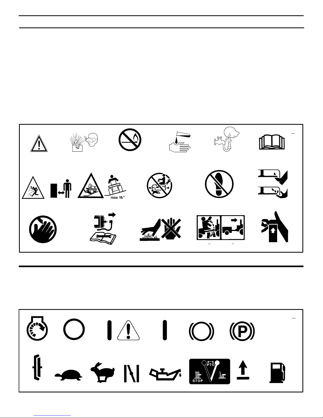
REGLAS DE SEGURIDAD
71
SIMBOLOS INTERNACIONALES
IMPORTANTE: Los siguientes símbolos
están ubicados en su unidad o indicados en la información impresa que está
incluida con el producto. Antes de usar
la unidad, debe familiarizarse con el
significado y propósito de cada
símbolo.
Símbolos de seguridad
1 Advertencia
2 Proteja los ojos. Gases potencialmente ex-
plosivos le pueden enceguecer o lesionar.
3 Evite chispas y llamas. No fume.
4 El ácido sulfúrico puede causar ceguera o
quemaduras graves.
5 Limpie los ojos inmediatamente con agua.
Consiga asistencia médica inmediatamente.
6 IMPORTANTE: Lea el Manual del Usuario
antes de operar esta máquina.
7 ADVERTENCIA: Objetos pueden ser lanza-
dos de la máquina. Opere a una distancia
segura de otras personas. Lea el Manual
del Usuario antes de operar esta máquina.
8 ADVERTENCIA: No use esta máquina en
cuestas de más de 15 grados.
9 PELIGRO: Mantenga a otras personas,
particularmente niños, a una distancia segura de esta máquina.
10 PELIGRO: No pisar.
11 PELIGRO: Mantenga los pies y las manos
a una distancia segura de la cuchilla en
movimiento.
12 PELIGRO: Mantenga las manos a una dis-
tancia segura de la cuchilla en movimiento.
13 PELIGRO: Desconecte el cable de la bujía
antes de realizar cualquier reparación en la
máquina.
14 ADVERTENCIA: Superficie caliente.
15 ADVERTENCIA: Tenga cuidado al conectar
o desconectar los accesorios.
16 ADVERTENCIA: Puede lesionar grave-
mente la mano.
MAX 90N+MAX 150N
+
12 3 546
7
8
9
10
12
11
13
14
15
16
3
Símbolos de control y funcionamiento
1 Arranque del motor
2 Parada del motor
3 Select Reverset
4 Motor en marcha
5 Freno
6 Freno de mano
7 Embrague
8 Marcha lenta
9 Marcha rápida
10 Cebador
11 Aceite
12 Dirección de rotación de la cuchilla
13 Levantar
14 Combustible
12 4 5 6
7
8
910 11
12
13
14
3
4
400150
Page 72

PREPARACIÓN
72
PREPARACIÓN
Lea y siga las instrucciones de preparación para su cortacésped.
Todos los sujetadores se encuentran en la bolsa de piezas. No tire
ninguna de las piezas ni materiales hasta que haya acabado de
montar la unidad.
NOTA. En este manual de instrucciones, el lado derecho o izquierdo describe la ubicación de una pieza desde el punto de
vista del cuando se encuentra sentado en la unidad.
ADVERTENCIA. Antes de hacer cualquier tipo de
preparación o de dar servicio al cortacésped, desconecte el cable de la bujía.
CÓMO SACAR LA UNIDAD DE LA CAJA
Para sacar la unidad de la caja, haga lo siguiente:
1. Ubique las dos lengüetas de separación ubicadas en la parte
superior de la caja de cartón.
2. Jale la cinta de separación por más de doce pulgadas a la vez.
3. Vuelva a tirar de la cinta de separación, esta vez haciéndolo
más cerca del cartón.
4. Una vez que la cinta de separación ha sido retirada completamente de ambos extremos, saque el marco de madera y colóquelo a un lado.
5. Repita el proceso en las lengüetas de separación de la parte inferior de la caja de cartón.
6. Coloque los paneles a un lado.
7. Mueva la palanca de cambios a la posición neutro (N).
NOTA: Consulte la página 80 en la sección de Operación,
para ver la ubicación de los controles.
8. Si el freno de estacionamiento está enganchado, pise a fondo
el pedal de embrague / freno para desenganchar el freno
9. Mueva la palanca de elevación a la posición más alta.
PRECAUCIÓN: Revise el fondo de la caja de cartón por si
quedaran algunas grapas. Retire cualquier grapa que se
encuentre en el camino de los neumáticos.
10. Retire el cortacésped de la plataforma de envío.
CONTENIDO DE LA BOLSA DE PIEZAS SUELTAS
Folleto informativo
Aditamento para descarga lateral
400150
Page 73
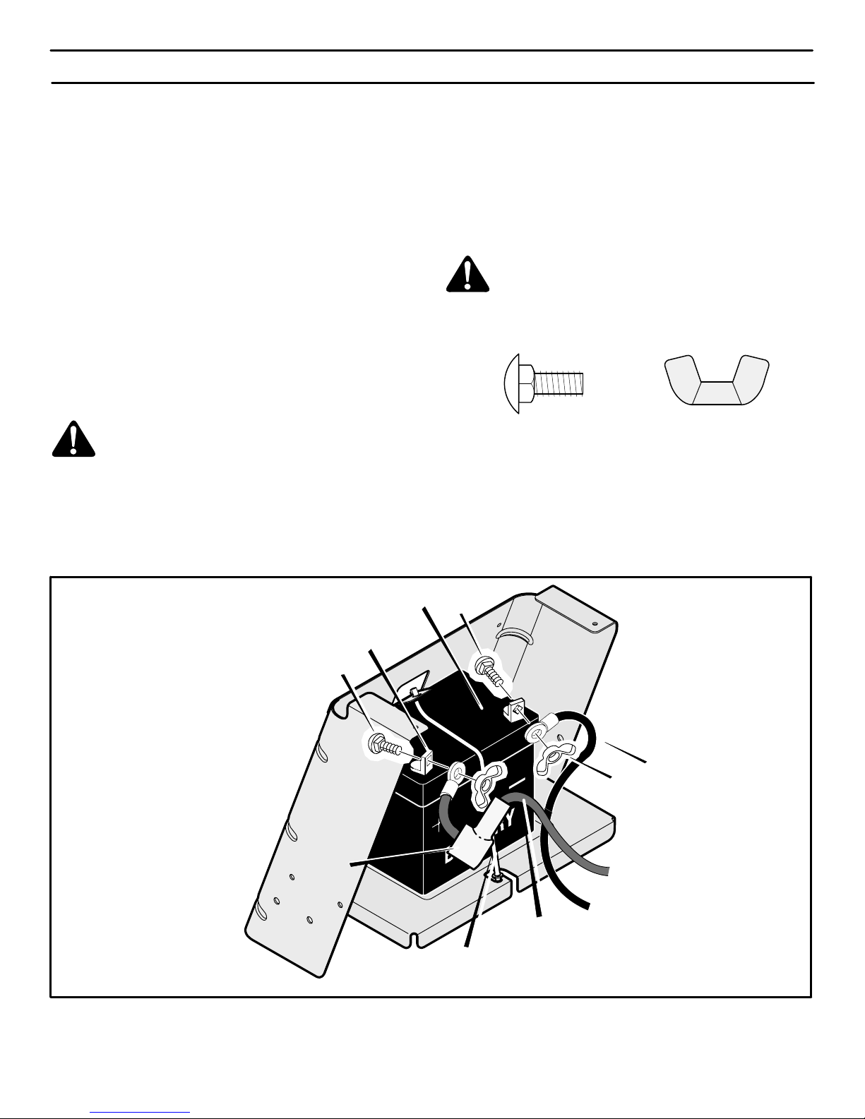
PREPARACIÓN
73
BATERÍA LIBRE DE MANTENIMIENTO
IMPORTANTE. Antes de conectar los cables de batería a la
batería, compruebe la fecha de la misma. Esta fecha le indicará
si necesita cambiar la batería.
1. Levante el soporte del asiento y fíjelo en la posición
LEVANTADA con la varilla del soporte.
2. Revise la parte superior y los lados de la batería (1) para la
ubicación de la fecha de la batería. (Figura 45).
3. Si la batería va a entrar en servicio antes de la fecha de la
batería, puede conectar los cables sin cambiar la batería.
Consulte “Cómo instalar los cables de la batería”.
4. Si la batería va a entrar en servicio después de la fecha de la
batería, tendrá que cargarla. Consulte “Cómo cargar una
batería sin mantenimiento”.
CÓMO CARGAR UNA BATERÍA
LIBRE DE MANTENIMIENTO
ADVERTENCIA. No fume cuando esté cargando la
batería. No deje que le lleguen chispas. Los vapores
de la batería podrían provocar una explosión.
1. Para desconectar la abrazadera de la batería de la bandeja,
empuje el extremo inferior de la abrazadera.
2. Quite la batería desde el lado derecho de la unidad.
3. Quite las tapas protectoras de los bornes de la batería.
4. Use un cargador de baterías de 12 voltios para cargar la
batería. Cárguela a una velocidad de 6 amperios por hora. Si
no tiene un cargador, lleve la batería a un agente autorizado de
Sears centro autorizado para que lo hagan por usted.
5. Instale la batería y fíjela en su sitio con su sujetador. El
terminal positivo (+) tiene que quedar a la derecha.
CÓMO INSTALAR LOS CABLES DE LA
BATERÍA
ADVERTENCIA. Para que no se produzcan chispas,
conecte el cable rojo al borne positivo (+) antes de conectar el cable negro.
Use los sujetadores que se muestran a continuación para instalar
los cables de la batería. Los sujetadores vienen junto con los
cables de la batería.
(B)
14x79
(A)
2x82
1. Quite las tapas protectoras de los bornes de la batería.
2. Conecte el cable rojo y el manguito protector al borne
positivo (+) con los sujetadores como se indica (Figura 45).
3. Conecte el cable negro al borne negativo (−) con los
sujetadores como se indica.
B
A
Borne
positivo (+)
Cable negro
Abrazadera de la batería
A
Batería
Figura 45
Cable rojo
Manguito
protector
400150
Page 74
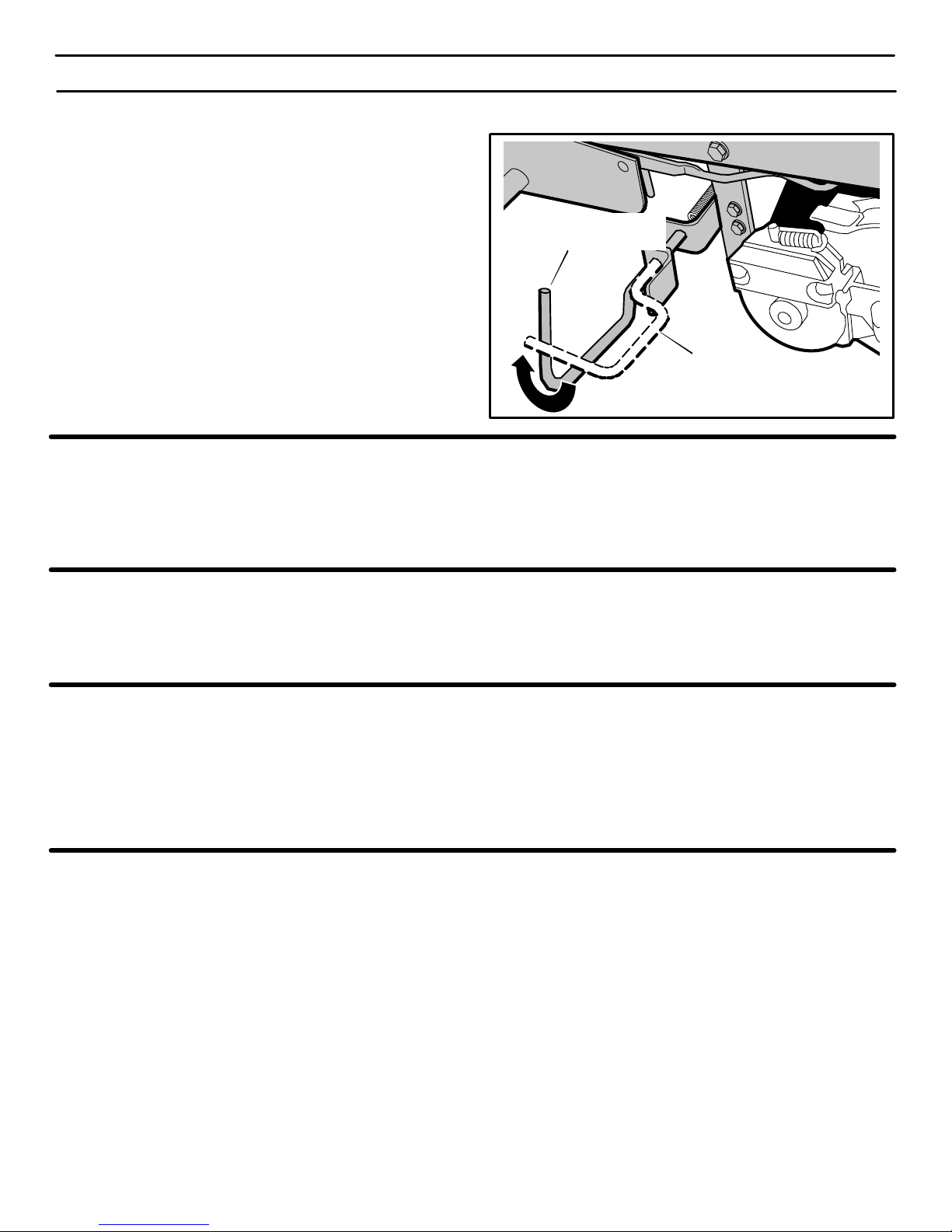
PREPARACIÓN
74
CÓMO CONECTAR LA TRANSMISIÓN
Para poder empujarla, la unidad fue enviada de fábrica con la barra
de desconexión automática de la transmisión en la POSICIÓN
DE EMPUJE. Antes de hacer funcionar la unidad es necesario
colocar la barra de desconexión automática de la transmisión en
la POSICIÓN DE OPERACIÓN. (Figure 46)
1. El motor debe estar apagado.
2. La desconexión automática de la transmisión está ubicada
debajo del lado izquierdo de la plataforma del asiento, junto al
eje transversal hidrostático.
3. Para activar la transmisión, quite el seguro de la desconexión
automática de la transmisión. La transmisión está ahora acti-
vada y lista para funcionar.
4. Para desenganchar la transmisión y empujar la unidad, jale y
gire la desconexión automática de la transmisión. Fije la
desconexión automática de la transmisión en la posición de
EMPUJE (Figura 1). La transmisión está ahora desactivada y
se puede empujar la unidad.
NOTA: En clima frío, la alta viscosidad del aceite de
transmisión hará que la unidad sea difícil de empujar.
Figure 46
Desconexión automática
de la transmisión
Desconexión automática
de la transmisión
POSICIÓN DE OPERACIÓN
POSICIÓN DE EMPUJE
CÓMO PREPARAR EL MOTOR
NOTA. El motor viene de fábrica lleno de aceite. Compruebe su
nivel (lea “Revise el aceite” en la sección de Operación). Añada
más aceite si es necesario.
NOTA: Cuando se opera un nuevo motor, a veces éste emite
algo de humo. Este humo se produce por pintura o aceite que
se encuentre sobre o cerca del mofle. Esto es normal y se
espera solamente durante la operación inicial.
Lea toda la información de seguridad, funcionamiento,
mantenimiento y almacenamiento antes de utilizar la unidad.
CÓMO REVISAR LOS NEUMÁTICOS
NOTA: Los neumáticos fueron sobreinflados para el envío. La
presión de aire correcta aparece en la cara lateral del
neumático.
Revise la presión de aire de los neumáticos. Demasiada presión
de aire en los neumáticos hará que la unidad salte. También, la
presión de aire incorrecta hará que el cárter de la cortadora de
césped corte en forma dispareja. La presión de aire (PSI) correcta
aparece en la cara lateral del neumático.
CÓMO REVISAR SI EL CÁRTER ESTÁ
NIVELADO
Asegúrese de haber cortado el césped de manera uniforme. Una
vez haya cortado un trozo, vuélvase a observarlo. Si el cárter no
está cortando de forma pareja, lea las instrucciones en “Cómo
nivelar el cárter” en la sección de Servicio y Ajuste de este manual
de instrucciones.
¡IMPORTANTE! ANTES DE EMPEZAR A CORTAR EL CÉSPED
- Revise el aceite del motor.
- Llene el tanque de gasolina.
- Revise la presión de aire en los neumáticos.
- Compruebe que el cárter esté nivelado.
- Asegúrese de que los cables de la batería estén
conectados.
- Asegúrese de que el cable esté conectado a la bujía.
400150
Page 75
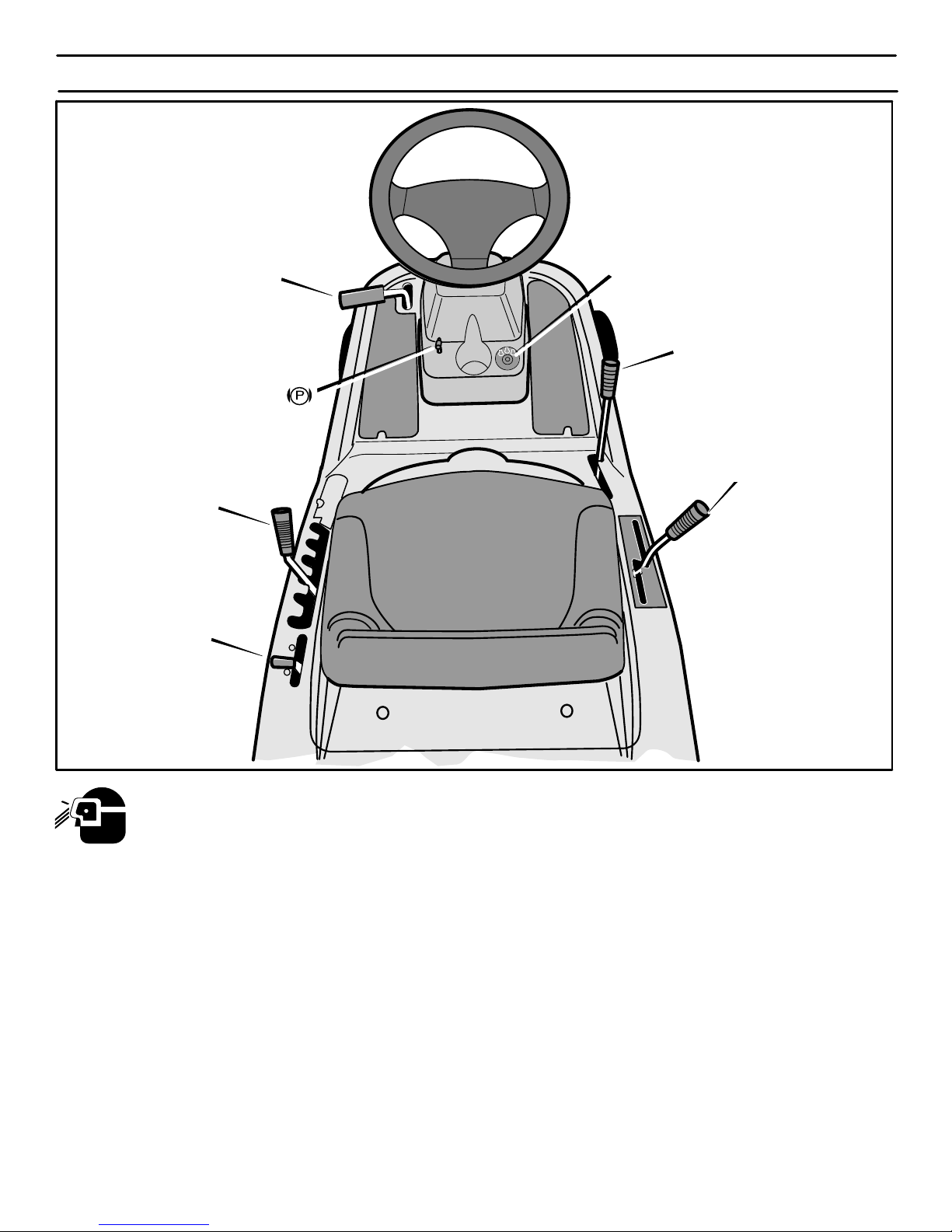
OPERACIÓN
75
Pedal de embrague y freno
Embrague de aditamento
Palanca de freno
de estacionamiento
Interruptor con llave de encendido
Palanca de elevación
Palanca de control
de velocidad
Palanca de control de
aceleración
Figura 47
La operación de cualquier cortadora de césped puede causar el lanzamiento de objetos extraños y lesionar los ojos,
lo cual puede resultar en daños graves a la vista. Siempre utilice gafas de protección o un protector para los ojos
antes de encender su cortadora de césped o mientras está cortando el césped. Recomendamos gafas de seguridad
estándar o una máscara de seguridad de visión amplia (Wide Vision Safety Mask) para colocar sobre los anteojos,
estos productos se encuentran disponibles en sus tiendas de Sears.
UBICACIÓN DE CONTROLES
EMBRAGUE DE ADITAMENTOS:
Utilice el embrague
de aditamentos para iniciar y parar la rotación de la cuchilla y para
operar el aditamento del quitanieves.
PEDAL DE EMBRAGUE Y FRENO: El pedal tiene dos
funciones. La primera función es de embrague. La segunda función
es de freno. Use el pedal de freno para detener rápidamente la marcha hacia adelante o la marcha hacia atrás de la unidad.
INTERRUPTOR CON LLAVE DE ENCENDIDO:
Utilice el interruptor con llave de encendido para encender y apagar
el motor. Cuando arranque el motor y suelte la llave de encendido, el
interruptor con llave de encendido irá automáticamente a la posición
del ajuste preestablecido recomendado MARCHA−CORTE para el
corte normal del césped.
PALANCA DE CONTROL DE VELOCIDAD Utilice
esta palanca para cambiar la velocidad y la dirección de la unidad.
PALANCA DE ELEVACIÓN: Utilice la palanca de eleva-
ción para cambiar la altura del corte.
PALANCA DE FRENO DE ESTACIONAMIENTO:
Utilice la palanca de freno de estacionamiento para enganchar el
freno cuando deja la unidad.
PALANCA DE CONTROL DE ACELERACIÓN:
Utilice la palanca de control de aceleración para aumentar o disminuir la velocidad del motor.
400150
Page 76
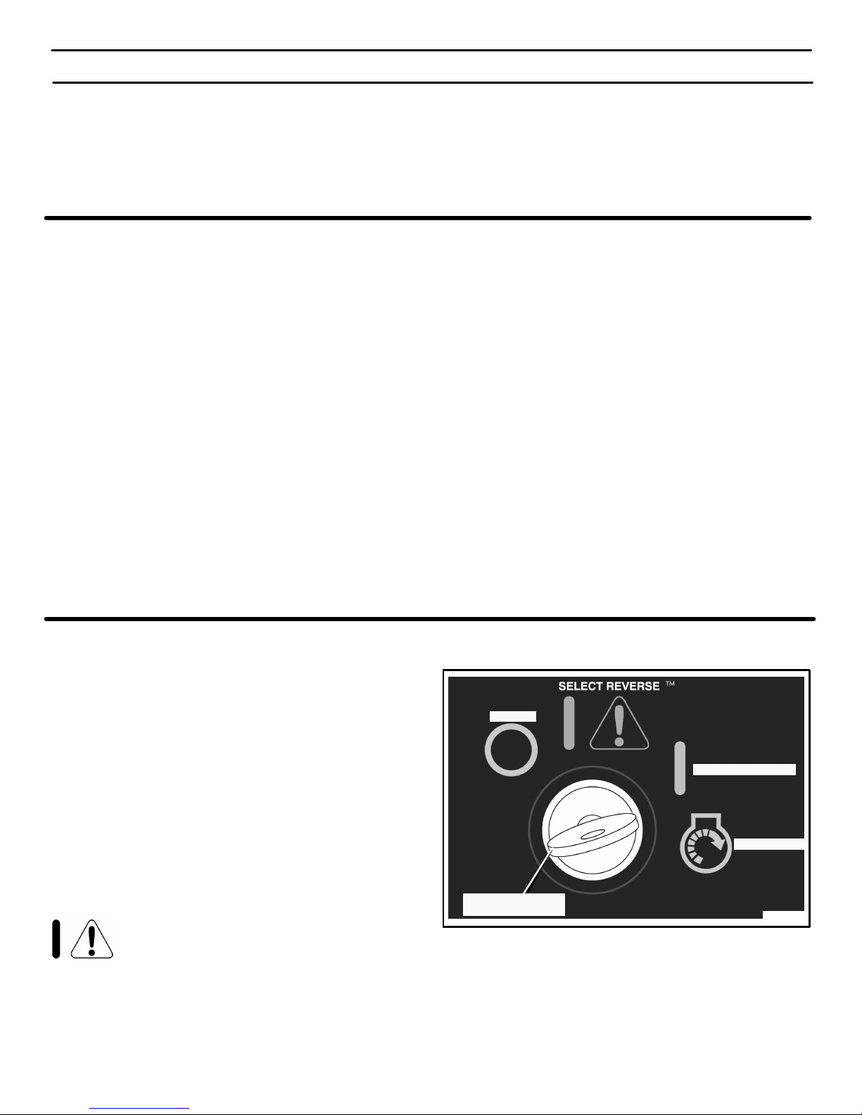
OPERACIÓN
76
ADITAMENTOS
Se puede adaptar una gran variedad de aditamentos a esta unidad.
Consulte la página de aditamentos en este manual. Esta máquina
tiene capacidad para arrastrar varios aditamentos tales como
rastrillo, aireador para césped, una esparcidora de tolva o un
remolque pequeño. Esta unidad puede usar aditamentos que
entren en la tierra como arados, gradas de disco o cultivadoras.
Para todos los aditamentos de arrastre o remolques, el peso bruto
máximo es de 200 libras. El peso bruto es el peso del aditamento
o remolque más la carga que lleve.
No operar la unidad en cuestas con una inclinación mayor que 10
grados cuando esté utilizando un aditamento o remolque de
arrastre. En este manual hemos incluido una guía de cuestas para
ayudarle a determinar la inclinación de la cuesta en la que estará
operando su unidad. Nunca permita que nadie se pare o vaya
montado sobre o dentro de un aditamento o remolque.
SISTEMA ELÉCTRICO DE SEGURIDAD
El sistema eléctrico tiene thes componentes principales, un
Sistema de funcionamiento en presencia del operador y un sistema
Select Reverset y un sistema Run-Mow (marcha−corte).
Sistema de funcionamiento en presencia del operador
(Asiento)
El asiento cuenta con un Sistema de funcionamiento en presencia
del operador el cual apaga el motor cuando el operador se levanta
del asiento. Este sistema no está diseñado para ser usado como
interruptor para apagar el motor o la rotación de la cuchilla(s)
normalmente. Antes de levantarse del asiento, mueva el control de
rotación de la cuchilla a la posición DESENGANCHE, mueva la
palanca de cambios a la posición neutro, enganche el freno de
mano y pare el motor.
Sistema Select Reverset
El sistema Select Reverset permitirá que la cuchilla(s) del
cortacésped siga girando cuando retrocede. Para más detalles
consulte “Operación del Interruptor con llave de encendido” y
“Arranque del motor”.
Cómo revisar los interruptores de seguridad
Siga los pasos a continuación para revisar el funcionamiento de los
interruptores de seguridad.
1. Revise el interruptor de embrague para aditamentos. Sién-
tese en el asiento. Pise el pedal de embrague/freno. Mueva el
embrague de aditamentos a la posición ENGRANAR. Coloque
el interruptor de encendido en la posición ARRANQUE. El motor no debe arrancar. Si el motor arranca, el interruptor está dañado y tendrá que reemplazarlo.
2. Revise el interruptor de embrague/freno. Siéntese en el
asiento. Mueva el embrague de aditamentos a la posición
DESENGRANAR. NO pise el pedal de embrague/freno. Coloque el interruptor de encendido en la posición ARRANQUE. El
motor no debe arrancar. Si el motor arranca, el interruptor está
dañado y tendrá que reemplazarlo.
3. Revise el interruptor del Sistema de funcionamiento en
presencia del operador. NO se siente en el asiento. Pise el
pedal de embrague/freno. Mueva el embrague de aditamen-
tos a la posición DESENGRANAR. Coloque el interruptor de
encendido en la posición ARRANQUE. El motor no debe arrancar. Si el motor arranca, el interruptor está dañado y tendrá que
reemplazarlo.
4. Revise el interruptor Select Reverset. Siéntese en el asien-
to. Pise el pedal de embrague/freno. Mueva el embrague de
aditamentos a la posición DESENGRANAR. Arranque el motor
y coloque el control de propulsión en la posición de retroceso
(R). Con el motor en marcha, mueva el embrague de aditamentos a la posición ENGRANAR. El motor debería apagarse. Si
el motor sigue en marcha, el interruptor Select Reverset está dañado y tendrá que reemplazarlo.
OPERACIÓN DEL INTERRUPTOR CON LLAVE DE ENCENDIDO
Use el interruptor con llave de encendido para arrancar y parar el
motor. Cuando arranque el motor y suelte la llave de encendido, el
interruptor con llave de encendido irá automáticamente a la
posición del ajuste preestablecido recomendado
MARCHA−CORTE para el corte normal del césped.
ARRANQUE − Use esta posición para hacer arrancar el motor.
MARCHA-CORTE − Cuando usted arranque el motor y suelte la
llave de encendido, el motor con llave de encendido irá
automáticamente a la posición del ajuste preestablecido
recomendada MARCHA-CORTE para el corte normal del césped.
En la posición MARCHA-CORTE, el sistema parará el motor y la
cuchilla(s) cuando el pedal de control de velocidad / palanca de
cambios sea colocada en la posición de marcha atrás.
SELECT REVERSEt − La posición opcional Select Reverset
permitirá que la cuchilla(s) del cortacésped siga girando cuando
ponga la unidad en marcha atrás. Siempre use la posición
recomendada MARCHA−CORTE para el corte normal cuando
Select Reverset no sea absolutamente necesario. NUNCA use la
opción Select Reverset si hay niños en o cerca de la propiedad.
ADVERTENCIA: Se recomienda encarecidamente a los operadores que no usen esta opción, a
menos que el operador decida hacerlo porque dicha opción es absolutamente necesaria, y se han tomado todas las medidas de seguridad. Nunca use la opción Select
Reverset si hay niños en o cerca de la propiedad. Siempre
mire hacia abajo y hacia atrás cuando esté retrocediendo.
Después de usar la opción Select Reverset, mueva la llave
de encendido a la posición MARCHA−CORTE.
PARE − Use esta posición para parar el motor.
Figure 48
Interruptor con lla-
ve de encendido
ARRANQUE
MARCHA-CORTE
PARE
400150
Page 77
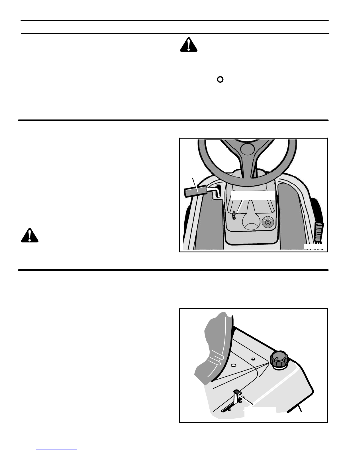
OPERACIÓN
77
CÓMO DETENER LA UNIDAD
1. Pise a fondo el pedal de embrague y freno para detener la
unidad. Mantenga su pie en el pedal.
2. Mueva el control de rotación de la cuchilla a la posición DESEMBRAGUE.
3. Mueva la palanca de control de velocidad a la posición NEUTRO.
4. Enganche el freno de estacionamiento.
Asegúrese de que el freno de estacionamiento detenga la unidad.
5. Mueva la palanca de control de aceleración a la posición LENTO.
6. Para apagar el motor, ponga la llave de encendido en la posición STOP
. Saque la llave.
PRECAUCIÓN: Para parar el motor, no mueva el control de
cebado a la posición CHOKE. Puede producir petardeo o
daño al motor
CÓMO ENGANCHAR EL FRENO DE ESTACIONAMIENTO
1. Pise a fondo el pedal de embrague y freno.
2. Levante la palanca del freno de estacionamiento
(Figura 49).
3. Retire su pie del pedal de embrague y freno y entonces suelte
la palanca del freno estacionamiento. Asegúrese de que el
freno de estacionamiento detenga la unidad.
4. Para soltar el freno de estacionamiento, pise a fondo el pedal
de embrague y freno. El freno de estacionamiento se soltará automáticamente.
ADVERTENCIA: Antes de dejar la posición de
operador, mueva la palanca de cambios a la posición
neutro (N). Enganche el freno de estacionamiento.
Mueva el control de rotación de la cuchilla a la
posición DESEMBRAGUE. Apague el motor y saque
la llave de encendido.
Figura 49
Palanca de freno de
estacionamiento
Pedal de
embrague
y freno
CÓMO USAR EL BOTÓN DE CONTROL DE
ACELERACIÓN / CEBADOR
PRECAUCIÓN: Opere siempre el motor con el control de
aceleración en la posición RÁPIDO. Si el motor corre por varios
minutos a una velocidad menor que la de la posición RÁPIDO,
el motor y la transmisión podrían recalentarse y dañarse.
Use el botón de control de aceleración / cebador para para
ahogar el motor cuando necesite arrancarlo en frío y aumentar o
disminuir la velocidad del motor (Figura 50).
1. Mueva el botón de control de aceleración / cebador hacia
adelante hasta la posición AHOGAR para arrancar el motor en
frío.
2. La posición RÁPIDO está marcada con un tope. En condiciones normales y cuando lleve un recolector de hierba, ponga el
control de aceleración en la posición RÁPIDO. Para cargar
la batería al máximo y cuando el motor funcione en frío, opere
el motor en la posición RÁPIDO.
3. Para transportar la unidad y para remolcar aditamentos de enganche, mueva el control de aceleración a la posición
LENTO.
4. El regulador de velocidad del motor ha sido ajustado en la fábrica para que usted obtenga el máximo rendimiento. No ajuste
el regulador para aumentar la velocidad del motor.
Palanca de
control de
aceleración
Figura 50
400150
Page 78
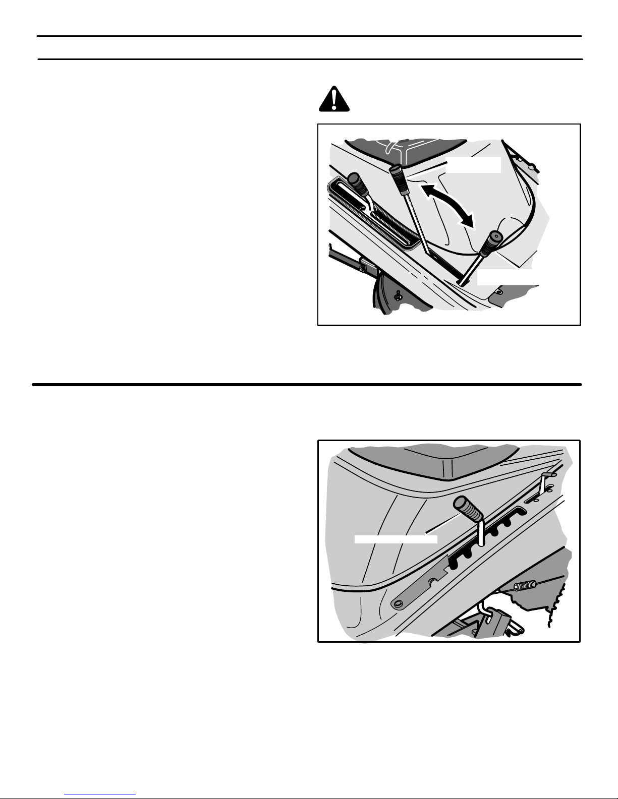
OPERACIÓN
78
CÓMO USAR EL EMBRAGUE DE ADITAMENTO
El embrague de aditamentos se usa para enganchar la cuchilla
(Figura 51).
1. Antes de arrancar el motor, asegúrese de que el embrague de
aditamentos esté en la posición DESEMBRAGUE.
2. Para que la cuchilla empiece a girar, mueva el embrague de
aditamentos hacia adelante para bloquear la cuchilla en la posición de EMBRAGUE.
NOTA: Si se apaga el motor al enganchar la cuchilla, la
transmisión está en marcha atrás.
3. Para detener la cuchilla, mueva el embrague de aditamentos
a la posición DESEMBRAGUE. Asegúrese de que la cuchilla
haya dejado de girar antes de dejar el asiento.
4. Si tiene que pasar con la máquina por una acera o carretera,
mueva el embrague de aditamentos a la posición de DES-
EMBRAGUE.
5. Antes de operar en marcha atrás, mueva el control de rotación
de la cuchilla a la posición DESENGANCHE. Si el control de
rotación de la cuchilla no está en la posición DESENGAN-
CHE, el motor se parará cuando el pedal de control de velocidad / palanca de cambios se mueva a la posición MARCHA
ATRÁS.
ADVERTENCIA. Nunca acerque las manos y los pies
a la cuchilla, a la abertura del deflector ni al cárter
mientras el motor esté en marcha.
Posición de embrague del
embrague de aditamentos
Posición de
desembrague
Figura 51
CÓMO CAMBIAR LA ALTURA DE CORTE
Para cambiar la altura de corte, levante o baje la palanca de
elevación según los pasos siguientes.
1. Mueva la palanca de elevación hacia abajo para bajar el cárter de la cortadora de césped y hacia arriba para levantar el cárter de la cortadora de césped (Figura 52).
2. Cuando Ud. conduce sobre una acera o una calle, mueva la
palanca de elevación a la posición más alta y mueva el control
de rotación de la cuchilla a la posición DESEMBRAGUE.
Figura 52
Palanca de elevación
400150
Page 79
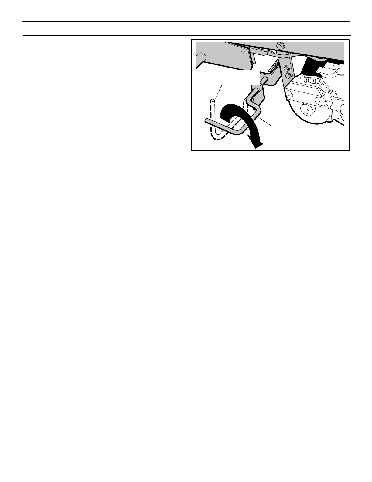
OPERACIÓN
79
CÓMO DESCONECTAR LA TRANSMISIÓN
Para empujar la unidad, use la desconexión automática para
desactivar la transmisión. (Figura 53)
1. El motor debe estar apagado.
2. La desconexión automática de la transmisión está ubicada
debajo del lado izquierdo de la plataforma del asiento, junto al
eje transversal hidrostático.
3. Para desenganchar la transmisión y mover la unidad, jale y gire
la desconexión automática de la transmisión y asugure la
desconexión automática de la transmisión en la posición de
EMPUJE (Figura 53). La transmisión está ahora desactivada
y se puede empujar la unidad.
NOTA: En clima frío, la alta viscosidad del aceite en la
transmisión hará que la unidad sea difícil de empujar.
4. Para activar la transmisión, quite el seguro de la desconexión
automática. La transmisión está ahora activada y lista para
funcionar.
Figura 53
Desconexión automática
de la transmisión
Desconexión automática
de la transmisión
POSICIÓN DE OPERACIÓN
POSICIÓN DE EMPUJE
400150
Page 80
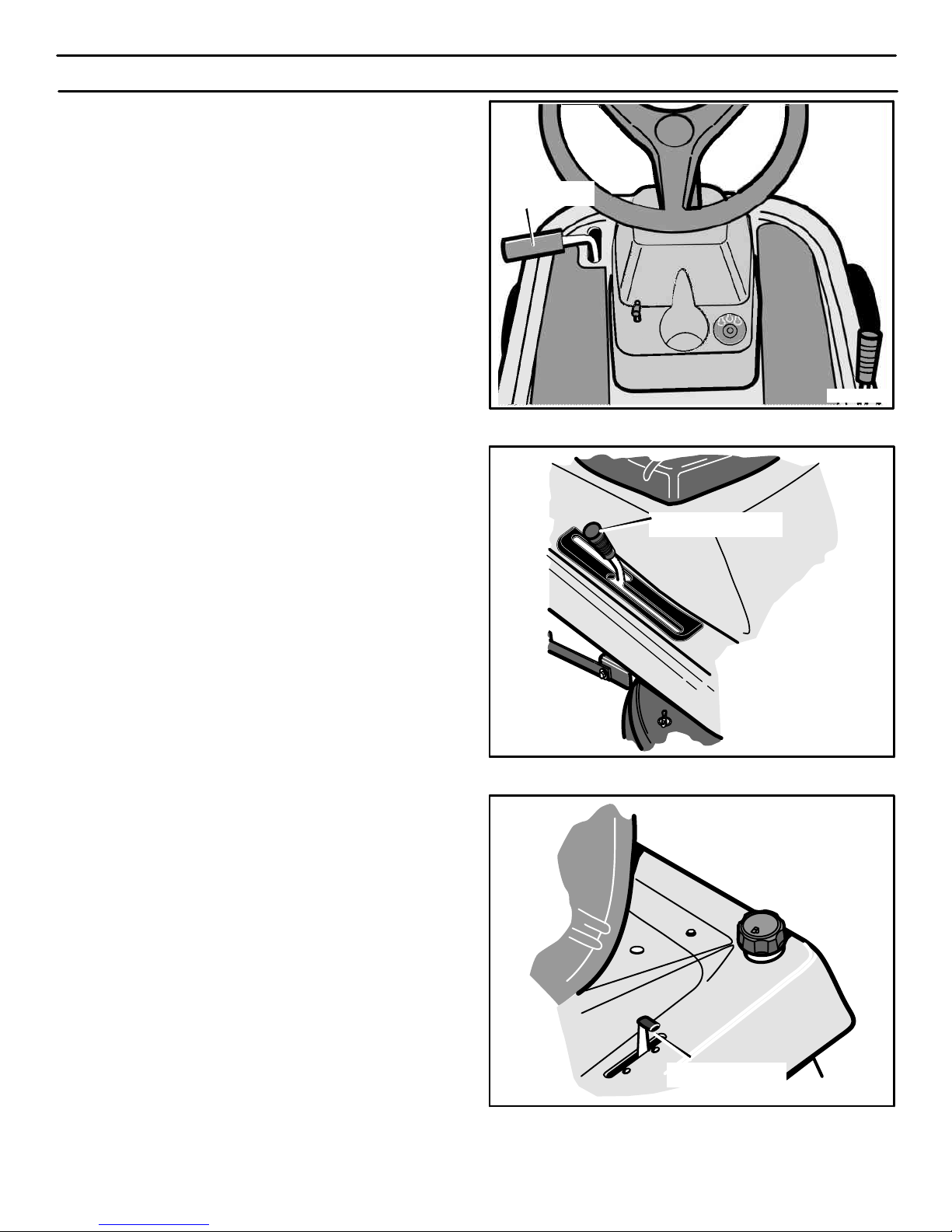
OPERACIÓN
80
CÓMO USAR LA PALANCA
DE CONTROL DE VELOCIDADES
La transmisión hidrostática es muy fácil de operar. El sistema de
transmisión tiene un pedal de embrague / freno en el lado izquierdo
(Figura 54) y una palanca de control de velocidades y dirección en
el lado derecho (Figura 55).
La velocidad y la dirección de avance son controladas por la
palanca de control de velocidades (Figura 55). Use la palanca de
control de velocidades tanto para avanzar como para retroceder.
CÓMO AVANZAR
1. La desconexión automática de la transmisión debe estar en
la posición de OPERACIÓN (Figura 53).
2. Apriete a fondo el pedal de embrague / freno para detener la
unidad (Figura 54). No suelte el pedal.
3. Mueva la palanca de control de velocidad a la posición NEUTRO (Figura 55).
4. Suelte lentamente el pedal de embrague / freno (Figura 54). No
deje el pie sobre el pedal.
5. Mueva el control de aceleración a la posición RÁPIDO
(Figura 56).
6. Empuje lentamente la palanca de control de velocidades hasta
alcanzar la velocidad deseada (Figura 54).
CÓMO CAMBIAR DE DIRECCIÓN / MARCHA ATRÁS
1. Siempre desenganche las cuchillas y mire hacia abajo y hacia
atrás mientras está retrocediendo.
2. Mueva la palanca de control de velocidades a la posición NEUTRO (Figura 55).
3. Para retroceder, mueva la palanca de control de velocidades
a la posición de MARCHA ATRÁS.
Pedal de
embrague/ freno
Figura 54
Palanca de control de
velocidades
Figura 55
Palanca de control
de aceleración
Figura 56
400150
Page 81
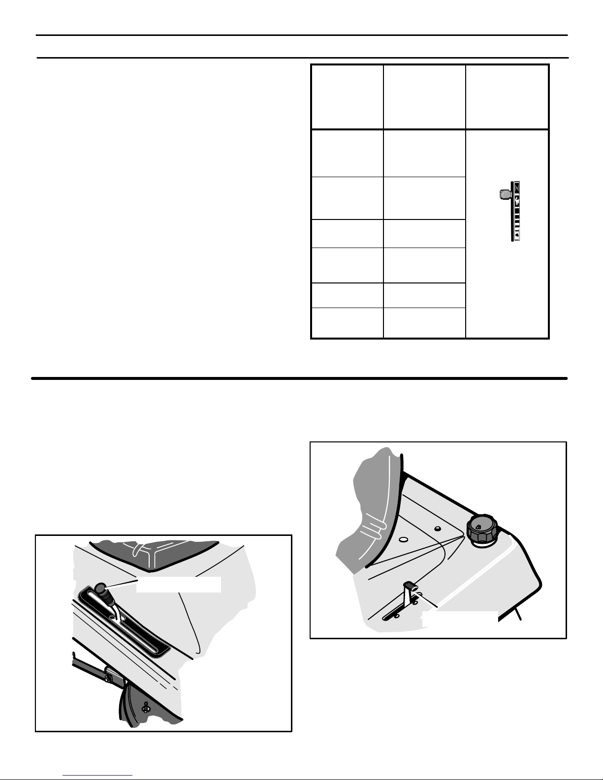
OPERACIÓN
81
POSICIONES DE LA PALANCA
DE CONTROL DE VELOCIDADES
La velocidad de avance se controla por la posición de la palanca
de control de velocidades. El cuadro siguiente incluye las
funciones junto con las posiciones correspondientes de la palanca
de control de velocidades. Siempre opere el motor con el control
de aceleración en la posición RÁPIDO.
FUNCIÓN
POSICIÓN DE
LA PALANCA DE
CONTROL DE
VELOCIDADES
CONTROL DE
ACELERACIÓN
Recorte
Cuestas inclinadas
1/3
RÁPIDO
AHOGAR
RÁPIDO
LENTO
ACELERACIÓN
Recogido de
hierba
1/3 a 1/2
Corte normal 1/2 a 2/3
Corte ligero
1/2 a 3/4
Transporte TOTAL
Remolques
1/3 a 1/2
CÓMO TRANSPORTAR LA UNIDAD
Para transportar la unidad, siga los pasos siguientes.
1. Mueva el embrague de aditamento a la posición
DESENGANCHADO.
2. Levante la palanca de elevación a la posición más alta.
3. Mueva la palanca de control de aceleración a una posición
RÁPIDO (Figura 58).
4. Para avanzar más rápido, mueva la palanca de control de
velocidades a una velocidad más rápida (Figura 57).
Palanca de control de
velocidades
Figura 57
Palanca de control
de aceleración
Figura 58
400150
Page 82
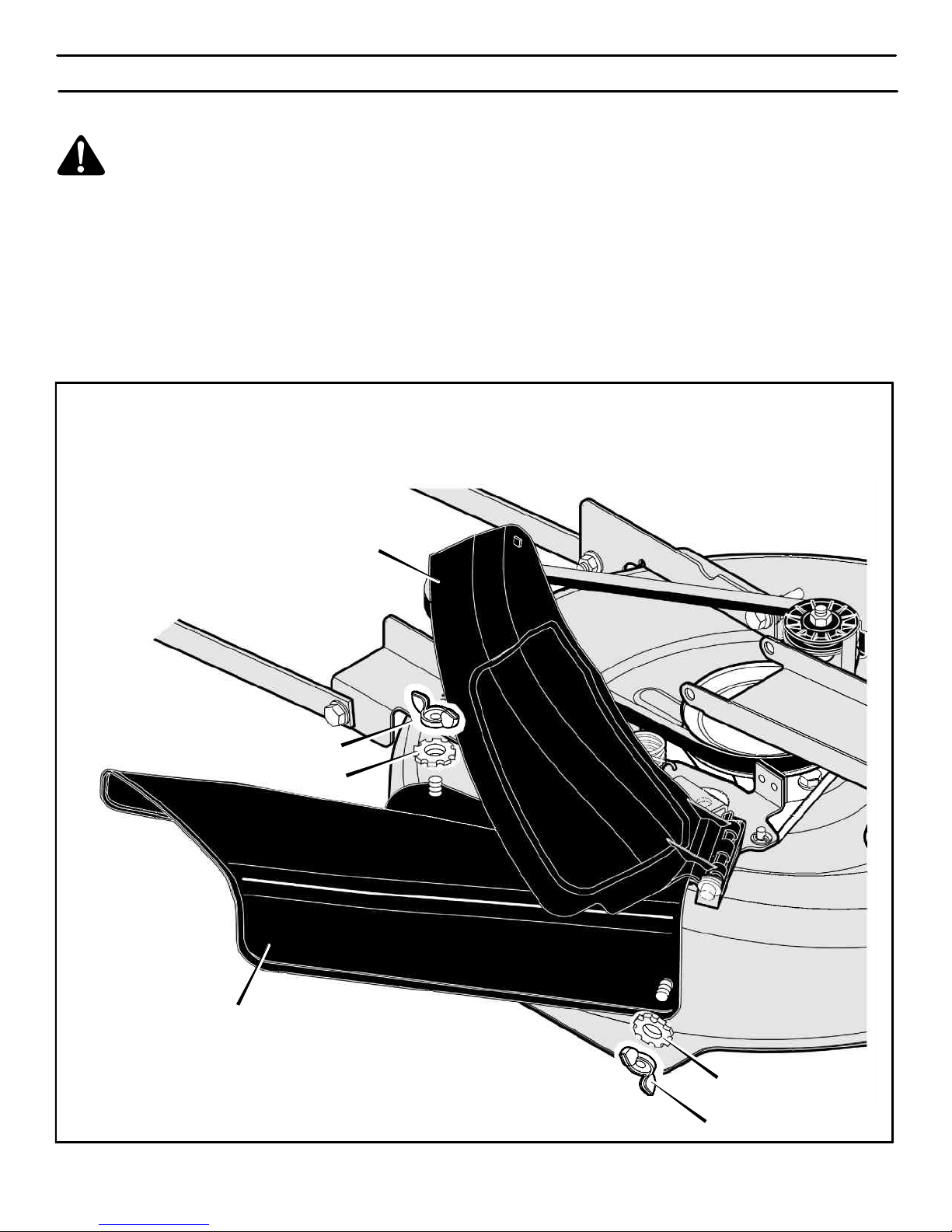
OPERACIÓN
82
CÓMO DE INSTALAR EL ADITAMENTO PARA DESCARGA LATERAL
ADVERTENCIA. Para evitar que el motor arranque,
desconecte el cable de la bujía. El embrague del aditamento tiene que estar en la posición de DESEMBRAGUE.
La cubierta para trituradora le permite triturar la hierba para
obtener un corte más fino y limpio. Para descargar la hierba por el
lado, instale el aditamento para descarga lateral de la siguiente
manera.
1. Desatornille las dos tuercas de mariposa (Figura 59).
2. Levante la cubierta para trituradora. Monte el aditamento de
descarga lateral en los mismo pernos que sujetaban la cubierta para trituradora.
3. Sujete el aditamento de descarga lateral con las tuercas de
mariposa.
4. Para triturar la hierba, quite el aditamento de descarga lateral
e instale la cubierta para trituradora en el cárter del cortacésped usando las tuercas de mariposa.
Figura 59
Aditamento de descarga lateral
Cubierta para trituradora
Tuerca de mariposa
Tuerca de mariposa
Arandela
Arandela
400150
Page 83
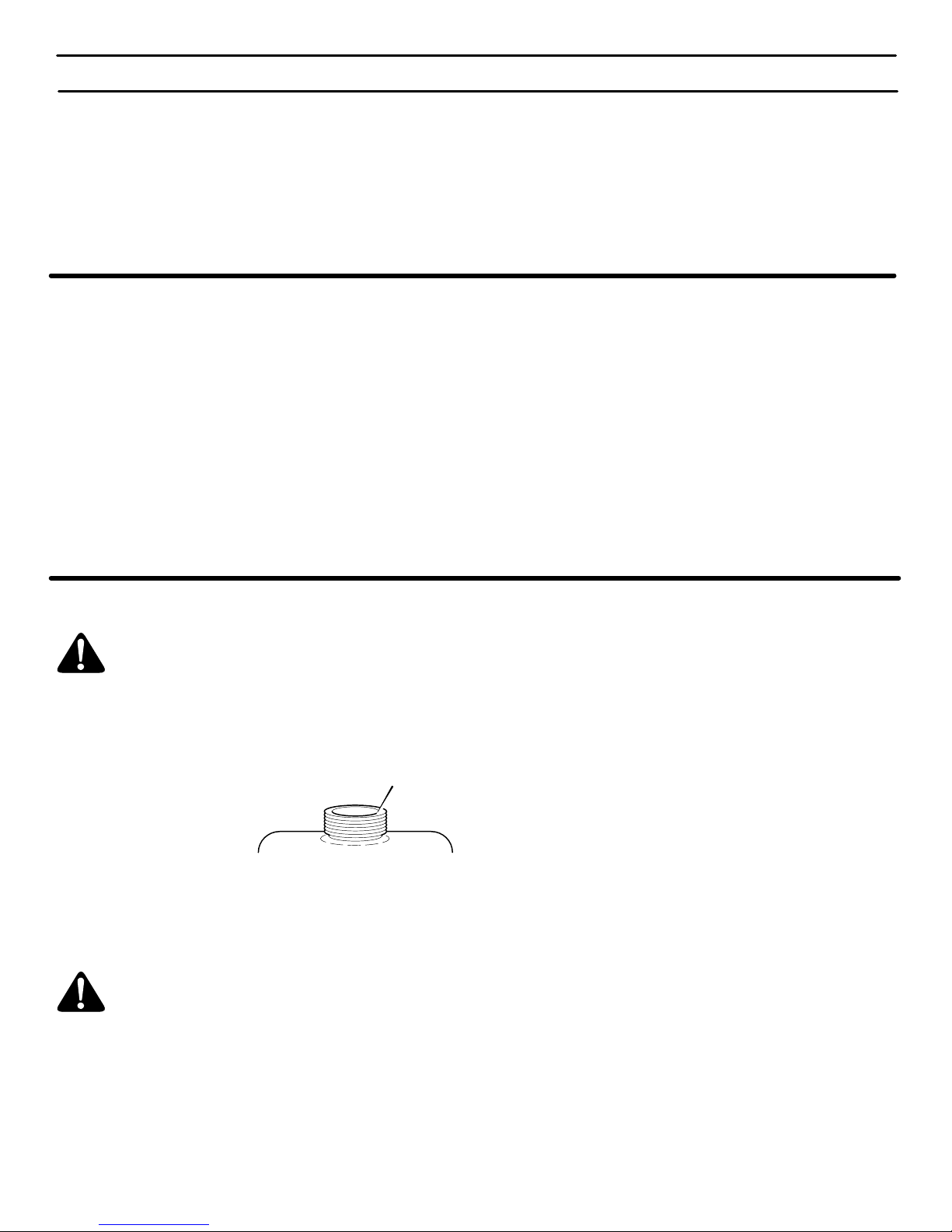
OPERACIÓN
83
ANTES DE ENCENDER EL MOTOR
REVISE EL ACEITE
NOTA: La unidad fue enviada desde la fábrica con el motor
lleno de aceite de peso 30. Revise el nivel del aceite. Agregue
aceite, según sea necesario.
1. Asegúrese de que la unidad esté nivelada.
NOTA: No revise el nivel del aceite cuando el motor esté en
marcha.
2. Limpie las partes alrededor de la varilla indicadora del nivel de
aceite. Retire la varilla indicadora. Limpie el aceite de la varilla.
3. Inserte la varilla indicadora dentro del tubo para agregar aceite.
Gire la varilla indicadora hacia la derecha hasta que esté apretada. Retire la varilla indicadora y revise el nivel del aceite. El
nivel de aceite debe llegar hasta la marca LLENO en la varilla.
4. Si sea necesario, agregue aceite hasta que el aceite llegue
hasta la marca LLENO en la varilla indicadora. La cantidad de
aceite necesaria desde AGREGAR a LLENO se muestra en la
varilla indicadora. No agregue demasiado aceite.
REQUISITOS DE GASOLINA
No cualquier gasolina es igual. Si detecta un problema de arranque
o de rendimiento luego de usar una gasolina nueva, pruebe con otra
estación de servicio o cambie de marca.
Tipo de gasolina a utilizar
Siempre use gasolina que cumpla con estos requisitos:
¯ Gasolina limpia, fresca, y sin plomo.
¯ Un mínimo de 87 octanos / 87 AKI (91 RON). Para altitudes
superiores a 5.000 pies, consulte a continuación la sección
“Uso para altitudes altas”.
¯ La gasolina con hasta un 10% de etanol (gasohol) o hasta
un 15% de MTBE (éter butílico terciario metílico) es
aceptable.
¯ El uso de otras gasolinas que no sean aquellas aprobadas
anteriormente invalidará la garantía del motor. Algunas
áreas requieren que se marquen las bombas de combustible
si la gasolina contiene alcoholes o éteres. Si no está seguro
de si su gasolina contiene alcohol o éteres que sean
diferentes a los aprobados anteriormente, consúltelo con el
operario de su estación de servicio.
¯ No modifique el sistema de combustible o el carburador del
motor para utilizar combustibles alternativos.
¯ Nunca mezcle aceite con gasolina.
Este motor está diseñado para operar con gasolina. El sistema de
control de emisiones para este motor es EM (Modificaciones del
Motor).
AGREGUE GASOLINA
ADVERTENCIA: Utilice siempre un recipiente aprobado de gasolina. No fume mientras agrega gasolina
al tanque de combustible. No agregue gasolina cuando esté en un lugar cerrado. Antes de agregar gasolina, apague el motor y déjelo que se enfríe durante varios minutos.
1. Apague el motor. Antes de retirar la tapa de gasolina , deje que
el motor se enfríe por lo menos 2 minutos.
2. Retire la tapa de gasolina.
Llene el tanque de combustible (B) hasta aproximadamente 1- 1/2 pulgadas por
debajo de la parte superior
del cuello para permitir la
expansión del combustible.
Tenga cuidado de no llenar
excesivamente.
3. Antes de arrancar el motor, vuelva a colocar la tapa del tanque
de gasolina.
ADVERTENCIA: La gasolina es inflamable y debe tener mucho cuidado al manipularla o alamcenarla.
S Apague el motor y deje que se enfríe por lo menos por
dos minutos antes de quitar la tapa del tanque de combustible.
S No llene el tanque de combustible mientras el motor se
encuentre en marcha, cuando esté caliente, o cuando
equipo se encuentre en un área cerrada.
S Mantenga la unidad alejada de llamas abiertas o chispas
eléctricas y no fume mientras llena el tanque de combustible.
S Nunca llene el tanque completamente, Llene el tanque
hasta dejar entre 1−1/2 pulgada aproximadamente de la
boquilla del tanque para proporcionar espacio para la expansión del combustible.
S Siempre llene el tanque al aire libre y use un embudo o
boquilla para prevenir el derrame.
S Asegúrese de limpiar cualquier combustible derramado
antes de arrancar el motor.
S Almacene la gasolina en un contendor, limpio y aprobado,
y mantenga la tapa puesta y segura en el contenedor.
PRECAUCIÓN: Los combustibles mezclados con alcohol
(llamados gasohol o aquellos que usan etanol), pueden atraer
humedad lo cual causa la separación y formación de ácidos
durante el almacenamiento de la unidad. La gasolina que
contiene ácidos puede dañar el sistema de combustible de un
motor mientras la unidad se encuentra almacenada.
Para evitar problemas con el sistema de alimentación de
combustible, vacíe éste último antes de guardar la unidad por 30
días continuos o más, siguiendo los pasos siguientes.
1. Drene el tanque de combustible.
2. Encienda el motor. Deje que el motor funcione hasta que las líneas de combustible y el carburador estén vacíos.
3. Después de haber guardado la máquina, asegúrese de utilizar
combustible fresco. Consulte las instrucciones de almacenamiento para información adicional.
4. Nunca utilice limpiador de motor o limpiador de carburador en
el sistema de alimentación de combustible, ya que podrían
ocurrir daños permanentes.
tanque de combustible
400150
Page 84
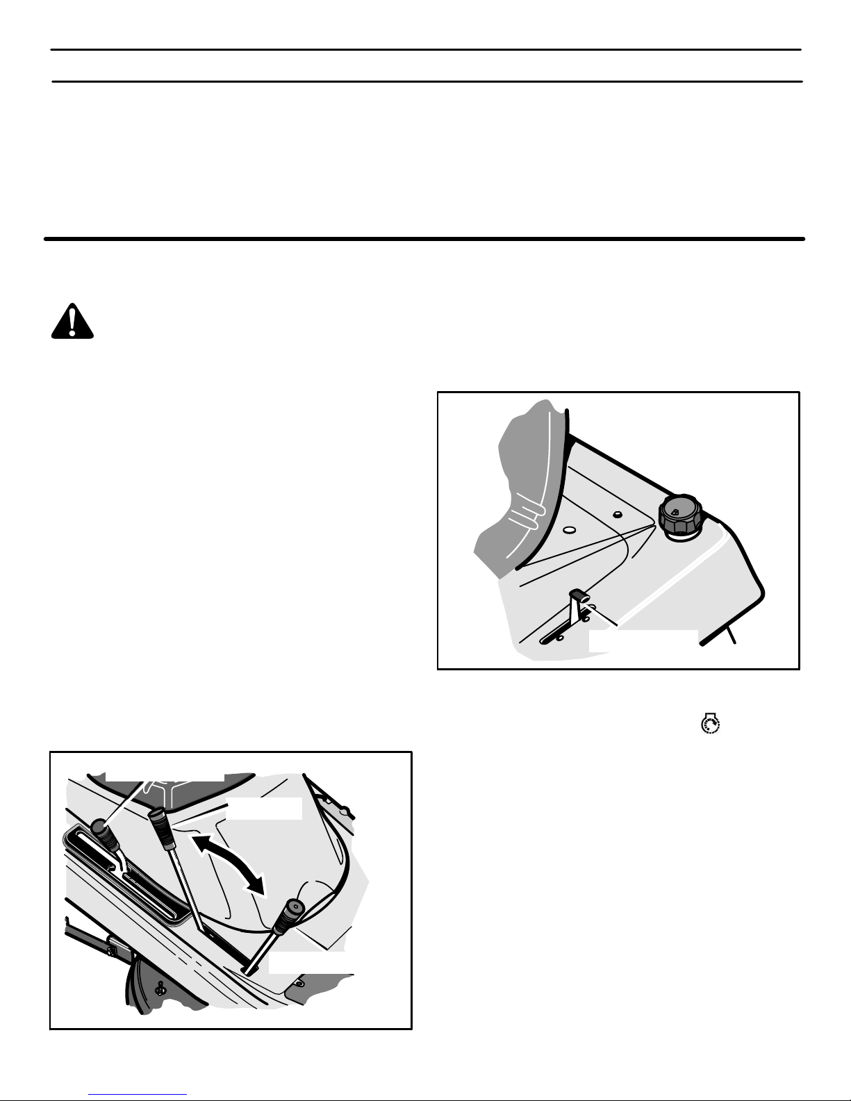
OPERACIÓN
84
CARBURADOR
Los ajustes de fábrica para el carburador son para la mayoría de las
condiciones. Si el motor funciona bajo las condiciones siguientes,
es posible que el carburador requiera un ajuste. Para servicio
consulte a un agente autorizado de Sears.
1. El motor tiene una pérdida de potencia o no funciona suavemente.
2. Un cambio de operación de verano a invierno.
3. Un cambio en la temperatura de operación de más de 40 grados. El carburador fue ajustado a 80 grados en la fábrica.
4. El motor está funcionando por encima de los 4000 pies (1219
m) sobre el nivel del mar.
CÓMO ARRANCAR EL MOTOR
ADVERTENCIA: El sistema Select Reverset per-
mite al operador cortar temporalmente en reversa si
él o ella considera tal operación absolutamente necesaria y se hayan tomado las medidas de seguridad necesarias. Para su protección, siempre comprueba que estos sistemas están fuADVERTENCIA: El sistema eléctrico tiene dos
componentes principales, un sistema de funcionamiento en
presencia del operador y un sistema Select Reverset. El sistema de funcionamiento en presencia del operador determina si el operador se encuentra sentado en el asiento. Este sistema hará parar el motor cuando el operador se levante del
asiento. El sistema Select Reverset permite al operador cortar temporalmente en reversa si él o ella considera tal operación absolutamente necesaria y se hayan tomado las medidas de seguridad necesarias. Para su protección, siempre
comprueba que estos sistemas están funcionando correctamente.
NOTA: El motor no arrancará a menos que usted pise el pedal
de embrague y freno, o enganche el freno de estacionamiento
y mueva la palanca de embrague de aditamentos a la posición
de DESEMBRAGUE.
1. Reconecte el cable a la bujía.
2. Mueva la palanca de control de velocidades a la posición neutro
(N) (Figure 60).
3. Asegúrese de que el embrague de cuchilla esté en la posición
DESEMBRAGUE. Si el control de rotación de la cuchilla no está en la posición DESENGANCHE, el motor no arrancará.
Posición de embrague del
embrague de aditamentos
Posición de
desembrague
Figure 60
Control de velocidades
4. Empuje completamente hacia adelante la palanca de de control de aceleración hasta la posición AHOGAR o RÁPIDO
(Figure 61).
Palanca de control
de aceleración
Figure 61
5. Gire la llave de encendido a la posición ARRANQUE.
Suelte la llave cuando el motor arranque. Cuando el motor
arranque, suelte la llave de encendido. El interruptor con llave
de encendido irá automáticamente a la posición del ajuste
preestablecido recomendado MARCHA−CORTE para el corte
normal del césped. Consulte “Operación del Interruptor con llave de encendido” en la sección de Operación.
NOTA: Si el motor no arranca después de cuatro o cinco
intentos, mueva el acelerador a la posición RÁPIDO.
Intente arrancar el motor otra vez. Si el motor no arranca,
consulte la TABLA DE LOCALIZACIÓN DE AVERÍAS.
6. Mueva lentamente el control de aceleración a la posición LENTO.
7. Deje que un motor frío esté en marcha durante varios minutos.
Comience a cortar el césped una vez que el motor se caliente.
Para arrancar un motor caliente, mueva el acelerador a una posición entre RÁPIDO y LENTO.
400150
Page 85
OPERACIÓN
85
CÓMO OPERAR, CON EL CÁRTER DE LA CORTADORA
ADVERTENCIA: La cubierta para trituradora es un
dispositivo de seguridad. No la quite. El deflector
fuerza el material cortado hacia la tierra. Manténgalo
siempre en la posición hacia abajo. Si el deflector está dañado, reemplácelo con una pieza original obtenida en un Centro de Servicio Sears.
IMPORTANTE: Cuando opere con el cárter del cortacésped,
hágalo siempre con el control de aceleración colocado en la
posición RÁPIDO.
1. Empuje el pedal de embrague y freno completamente hacia
adelante.
2. Arranque el motor.
3. Mueva la palanca de control de velocidades in la posición
NEUTRO.
4. Lentamente suelte el pedal de embrague y freno.
5. Mueva la palanca de elevación a una posición de altura de corte. Cuando la hierba está alta o densa, corte el césped en la
posición más alta primero y luego córtelo otra vez con el cárter
del cortacésped en una posición más baja.
PRECAUCIÓN: No opere la unidad con el cárter del
cortacésped en la posición de AJUSTE DE NIVEL. Si lo
hace, el cárter y las cuchillas del cortacésped pueden
resultar dañados.
6. Mueva el acelerador a la posición LENTO.
7. Mueva el embrague de aditamento a la posición de ENGANCHADO.
8. Mueva la palanca de control de velocidades hacia adelante.
NOTA: Cuando corta en césped denso o con una bolsa
recogedora, opere la unidad a una velocidad de avance
más baja.
9. Mueva el control de aceleración a la posición RÁPIDO. Si necesita ir más rápido o más despacio, mueva la palanca de
control de velocidades hacia adelante o hacia atrás.
10. Asegúrese de que el nivel de corte ajustado en la fábrica sea
correcto todavía. Después de cortar una corta distancia, observe el área que ha sido cortada. Si el cárter de la cortadora
no corta de forma pareja, consulte las instrucciones sobre “Cómo nivelar el cárter de la cortadora de césped” en la sección
de Servicio y Ajuste.
ADVERTENCIA: Para un mejor control de la unidad,
seleccione siempre una velocidad segura.
CÓMO OPERAR LA UNIDAD EN CUESTAS
ADVERTENCIA: No suba ni baje cuestas que son demasiado empinadas para poder retroceder en una línea recta. Nunca maneje la unidad a través de una
cuesta. Consulte la “Guía para cuestas” al final de este manual para obtener información sobre cómo evaluar las cuestas.
1. Antes de manejar cuesta arriba o cuesta abajo, mueva la palanca de control de velocidades a una velocidad más baja.
2. No pare la unidad ni cambie las velocidades cuando se
encuentre en una cuesta. Si debe parar, empuje rápidamente
el pedal de embrague y freno hacia adelante y enganche el freno de estacionamiento.
3. Para arrancar de nuevo, asegúrese de que la palanca de
control de velocidades esté en una velocidad más baja. Mueva
el control de aceleración a la posición LENTO. Y vaya soltando
lentamente el pedal.
4. Si debe parar o arrancar en una cuesta, tenga siempre suficiente espacio para que la unidad ruede cuando suelte el freno
y enganche el embrague.
5. Tenga mucho cuidado cuando cambia de dirección sobre una
cuesta. Cuando está en una cuesta o en una curva sobre la
cuesta, mueva el control de aceleración a la posición LENTO
para evitar accidentes.
400150
Page 86
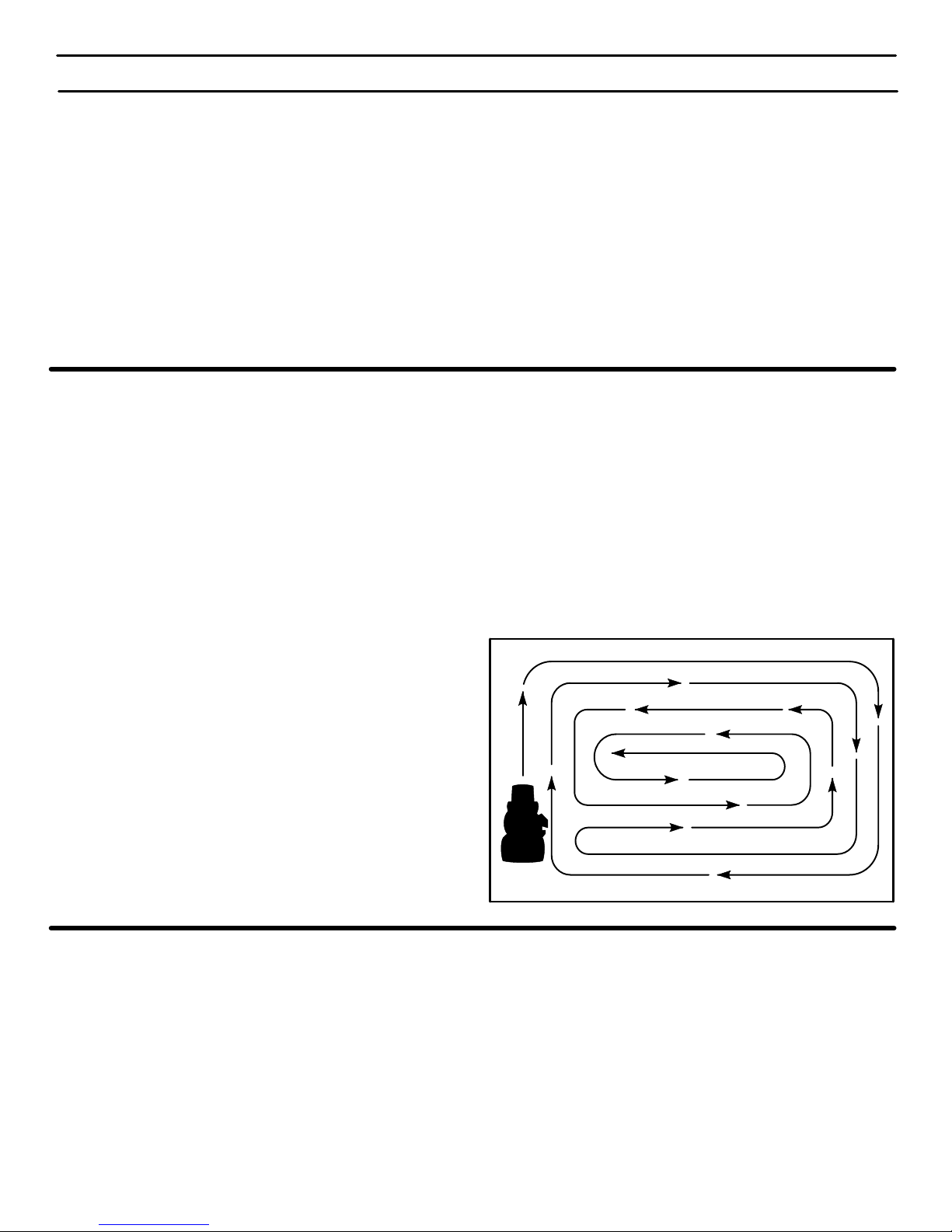
OPERACIÓN
86
SUGERENCIAS PARA LA OPERACIÓN
1. Examine el embrague de aditamentos para el ajuste correcto.
Para que la cuchilla (o cuchillas) desenganche correctamente,
el ajuste debe ser correcto.
2. Antes de usar la unidad, revise el aceite en el motor y añada
aceite si es necesario.
3. Si no se enciende el motor, primero asegúrese que esté conectado el cable a la bujía.
4. Asegúrese que todas las correas estén dentro de las guías de
correas. Consulte las instrucciones sobre cómo quitar e instalar las correas de transmisión de marcha y de transmisión de
la cortadora.
5. Antes de hacer una ejecute una inspección, un ajuste (con excepción del carburador), o una reparación, asegúrese que el
cable de la bujía esté desconectado.
6. Asegúrese de que el cable de interruptor del asiento esté conectado. Si el cable no está conectado, no se encenderá el motor.
7. Para una vida más larga de la batería, cárguela cada tres meses.
8. Utilice la palanca de cambios para cambiar la velocidad de vehículo, no el acelerador.
9. El ruido de la correa puede producirse cuando se engancha la
cuchilla o el embrague. Este ruido es normal y no afecta la operación de la unidad.
10. Para avanzar, siempre suelte lentamente el pedal de
embrague y freno.
SUGERENCIAS PARA EL CORTE Y REGOGIDA DE LA HIERBA
1. Para que el césped luzca mejor, examine el nivel de corte del
compartimento de cuchilla. Consulte “Cómo nivelar el cárter
del cortacésped” en la sección de Servicio y Ajuste.
2. Para asegurar el nivel correcto de corte, compruebe que los
neumáticos tengan una presión de aire adecuada y use poca
velocidad cuando esté dando la vuelta.
3. Cada vez que utilice la unidad, examine la cuchilla. Si la cuchilla está torcida o dañada, reemplácela inmediatamente. También, asegúrese que la tuerca para la cuchilla esté apretada.
4. Mantenga la cuchilla (o cuchillas) afilada. Las cuchillas gastadas causarán que las puntas del césped se tornen marrón.
5. No corte ni recoja la hierba cuando el césped esté mojado. La
hierba mojada no se descargará correctamente. Permita que
el césped se seque antes de cortarlo.
6. Utilice el lado izquierdo del cárter de la cortadora de césped para recortar cerca de algún objeto.
7. Descargue los recortes de la hierba sobre el área cortada. El
resultado es una descarga más pareja de los recortes de la
hierba.
8. Cuando se cortan áreas grandes, empiece por doblar a la derecha para que los recortes de la hierba se descarguen en sentido opuesto de los arbustos, las cerca, las entradas de autos,
etc. Después de una o dos vueltas, corte en la dirección opuesta dando vueltas hacia la izquierda hasta que termine
(Figura 62).
9. Siempre que pueda, use un patrón de corte que elimine la
necesidad de retroceder.
10. Si el césped está muy alto, córtelo dos veces para disminuir la
carga sobre el motor. Primero corte con el cárter de la cortadora de césped en la posición más alta y luego bájelo para el segundo corte.
11. Para un mejor rendimiento del motor y una descarga pareja de
los recortes de la hierba, siempre opere el motor con el acelerador en la posición RÁPIDO.
12. Cuando se utiliza una bolsa recogedora, opere el motor con el
control de aceleración en la posición RÁPIDO y la palanca de
control de velocidades usando una velocidad de avance más
lenta.
13. Para un mejor rendimiento del corte y un corte de calidad, corte
usando una velocidad de avance más lenta.
14. Después de cada uso, limpie la parte inferior y la parte superior
del cárter de la cortadora de césped para un mejor rendimiento.
Además, un cárter limpio ayudará a evitar un incendio.
Figura 62
SUGERENCIAS PARA USAR LA TRITURADORA
Cuando se utiliza el aditamento para triturar, se corta la hierba en
pedazos muy finitos. Estos pedazos se descompondrán muy
rápidamente. El césped necesitará menos abono porque los
alimentos nutritivos se vuelven a la tierra. Para triturar la hierba
correctamente, siga los pasos a continuación.
1. Ponga el control de aceleración en la posición RÁPIDO. Opere
la cortadora en una velocidad más lenta. Si la velocidad es demasiado rápida, el césped no tendrá un corte parejo.
2. Mantenga la cuchilla bien afilada. Una cuchilla desafilada causará que las puntas se tornen marrón.
3. Asegúrese que el césped esté seco. El césped mojado es muy
difícil de cortar.
4. Ponga la altura del cárter de la cortadora de césped para que
se corte solamente la tercera parte superior del césped. Si el
césped es demasiado alto, ponga la altura del cárter a la altura
máxima. Entonces, baje el cárter para un segundo corte. Además, en vez de usar la anchura completa del cárter, triture a la
mitad de la anchura.
5. Limpie el fondo del cárter de la cortadora de césped. Los recortes de la hierba y otros escombros puede impedir que la cortadora funcione correctamente.
6. Si la hierba crece rápidamente, triture con más frecuencia.
7. Si un área necesita un mejoramiento, triture una segunda vez.
400150
Page 87
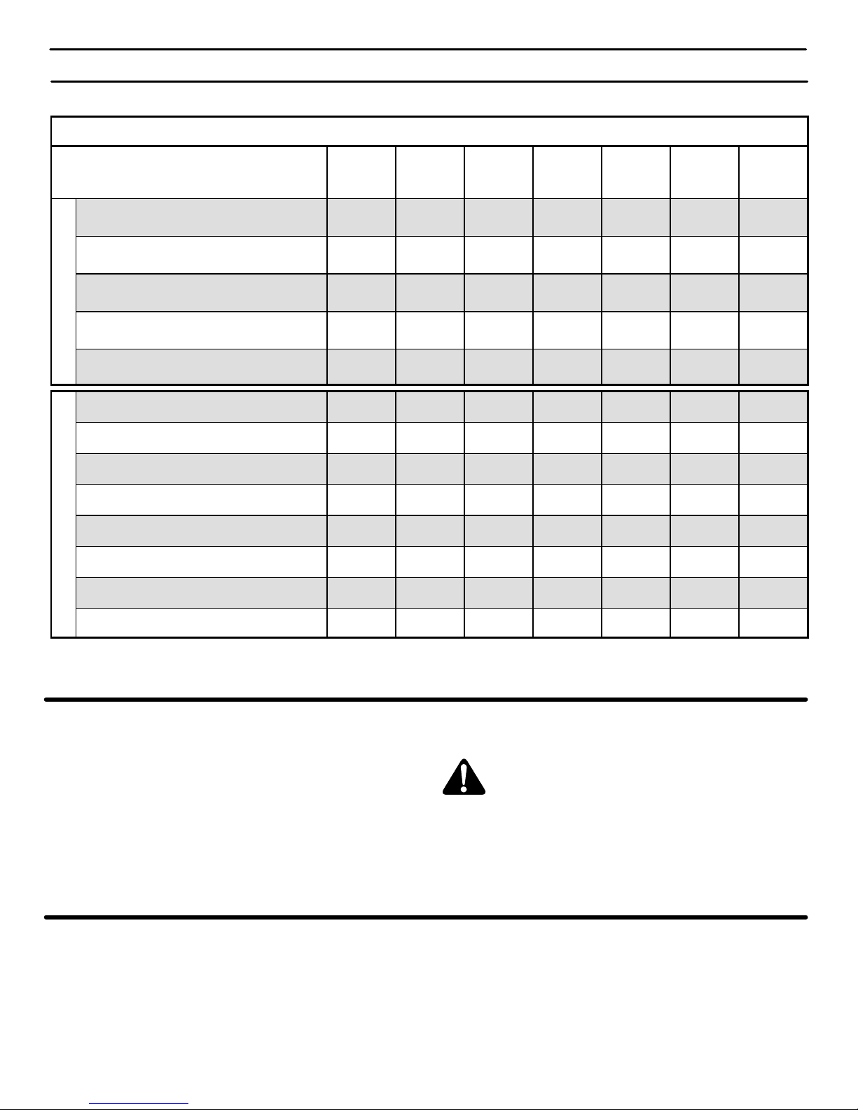
MANTENIMIENTO
87
TABLA DE MANTENIMIENTO
PROCEDIMIENTO
Cada
uso
Primeras
2
horas
Cada
8
horas
Cada
25
horas
Cada
50
horas
Cada
100
horas
Antes de
guardar
C
O
R
T
A
D
O
R
A
Neumáticos, Revisar
√
Cuchilla, Inspeccionar y Afilar
√
Batería, Revisar y Cargar
√ √
Batería, Limpiar
√ √
Lubricación
√ √
M
O
T
O
R
Aceite, Revisar
√ √
Aceite, Cambiar
√ √* √
Sistema de enfriamiento, Limpiar
√** √
Silenciador, Revisar
√ √
Filtro, Servicio
√
Portafiltro, Servicio
√
Bujía, Revisar
√ √
Bujía, Reemplazar
√
* Cambiar el aceite cada 25 horas cuando se opera la unidad con mucha carga o a temperaturas muy altas.
** Limpiar a menudo el sistema de enfriamiento si se opera la unidad en condiciones de mucho polvo.
RECOMENDACIONES GENERALES
1. El propietario es responsable de dar mantenimiento a este producto. Esto alargará la vida de la unidad y también es necesario para mantener la cobertura de garantía.
2. Revise la bujía y el freno motriz, lubrique la unidad, y limpie el
filtro de aire una vez al año.
3. Revise los sujetadores. Asegúrese de que todos los sujetadores estén apretados.
4. Siga las indicaciones de las secciones de Mantenimiento y de
Servicio y Ajuste para mantener la unidad en buenas condiciones de funcionamiento.
ADVERTENCIA: Antes de hacer una inspección, un
ajuste, o una reparación a la unidad, desconecte el
cable que va a la bujía. Quite el cable de la bujía para
prevenir que el motor se encienda por accidente.
Maintenance, replacement, or repair of the emission control devices
and systems may be performed by any Sears or other qualified
service dealer. El mantenimiento regular mejorará el rendimiento
y extenderá la vida útil del motor.
REVISIÓN DE LOS NEUMÁTICOS
Revise la presión de aire de los neumáticos. Demasiada presión
de aire en los neumáticos hará que la unidad salte. También, la
presión de aire incorrecta hará que el cárter de la cortadora de
césped corte en forma dispareja. La presión de aire (PSI) correcta
aparece indicada en la cara lateral de los neumáticos.
400150
Page 88
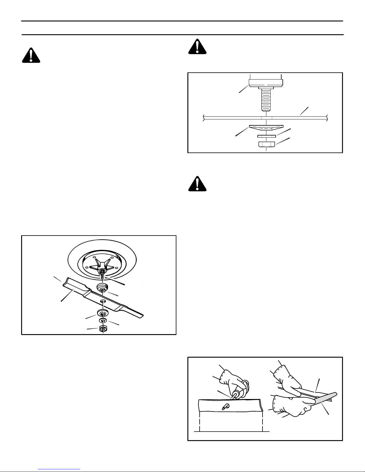
MANTENIMIENTO
88
INSPECCIÓN DE LA CUCHILLA
ADVERTENCIA: Antes de inspeccionar o sacar la
cuchilla, desconecte el cable de la bujía. Si la cu-
chilla golpea un objeto, pare el motor. Examine la
unidad por si tiene algún daño. La cuchilla tiene orillas muy
afiladas. Cuando sujete la cuchilla, use guantes o un pedazo de tela fuerte para proteger sus manos.
Si mantiene la cuchilla afilada y la revisa por si tiene algún daño,
la cuchilla cortará mejor y la unidad será más segura de operar.
Revise con frecuencia el estado de la cuchilla para detectar
desgaste excesivo, grietas u algún otro daño. Revise
periódicamente la tuerca que sujeta la cuchilla. Mantenga la
tuerca bien apretada. Si la cuchilla golpea un objeto, pare el
motor. Desconecte el cable de la bujía. Revise la cuchilla por si
estuviera doblada o dañada. Revise el adaptador de la cuchilla
por si estuviera dañado. Reemplace cualquier parte dañada con
repuestos originales, antes de operar la unidad. Si necesita
asistencia técnica, vaya a un Centro de Servicio Sears cercano a
usted. Cada tres años, haga que un técnico de servicio
cualificado inspeccione o reemplace la cuchilla vieja con una
cuchilla de repuesto original.
CÓMO DESMONTAR Y MONTAR LA CUCHILLA
Para sacar
1. Vacíe el tanque del combustible.
2. Levante el lado de la cortadora que contiene el silenciador o
la bujía.
3. Mientras afloja la tuerca, use un pedazo de madera para
inmovilizar la cuchilla.
4. Saque la tuerca, arandelas y cuchilla (vea la Figura 63).
Bordes eleva-
dos (hi−lift)
hacia arriba
Mandril
Adaptador de cuchilla
Cuchilla
Arandela Belleville
Arandela
Tuerca
Figura 63
5. Revise la cuchilla y el adaptador de cuchilla según se indi-
ca en las instrucciones de “Inspección de la cuchilla”. Reemplace una cuchilla muy desgastada o dañada con un
repuesto original de fábrica. Consulte con un Centro de Servicio Sears cercano a usted.
6. Limpie el fondo del cárter del cortacésped para quitar todo
resto de hierba y basura.
Para instalar
1. Monte la cuchilla y el adaptador de cuchilla en el mandril
(Figura 63).
2. Monte la cuchilla de manera que los bordes elevados queden hacia arriba. Si la cuchilla está puesta al revés, ésta no
cortará de la manera correcta y podría causar un accidente.
3. Sujete la cuchilla con las arandelas y tuerca originales.
Compruebe que el bordes externo de la arandela Belleville
quede contra la cuchilla (Figura 64).
ADVERTENCIA: Mantenga siempre apretada la
tuerca que sujeta la cuchilla. Una tuerca o cuchilla
floja puede causar un accidente.
4. Apriete la tuerca que sujeta la cuchilla con un par de apriete
35 libras−pie.
Adaptador de
cuchilla
Cuchilla
Arandela Belleville
(el borde externo debe
quedar contra la cuchilla)
Arandela
Tuerca
Figura 64
CÓMO AFILAR LA CUCHILLA
ADVERTENCIA: Si la cuchilla no está bien equilibrada o si está dañada, puede causar vibración en
la máquina. Una cuchilla dañada con grietas puede
provocar un accidente.
Mantenga la hoja de la cuchilla afilada. Una cuchilla desafilada
hará que las puntas de las briznas de hierba se tornen marrón.
1. Afile la cuchilla dos veces al año o cada 25 horas de uso.
2. Desmonte la cuchilla siguiendo las instrucciones que aparecen en la sección “Cómo desmontar y montar la cuchilla”.
3. Limpie la cuchilla con un cepillo, jabón y agua. Revise la
cuchilla. Fíjese si tiene grietas, muescas o algún otro daño.
Si la cuchilla está muy desgastada o dañada, reemplácela
con una cuchilla de repuesto original. Consulte en un Centro
de Servicio Sears de su área.
4. Afile la cuchilla con una lima (Figura 65). Asegúrese de
mantener ángulo oblicuo original.
5. Compruebe que la cuchilla esté bien balanceada. Use un
destornillador y sujete la cuchilla de manera que quede
paralela con el suelo (Figura 65). Si la cuchilla está bien
balanceada se mantendrá paralela al suelo. Si la cuchilla
no está bien balanceada, el extremo más pesado girará hacia el suelo. Afile el extremo pesado hasta que la cuchilla
quede bien balanceada.
6. Una cuchilla nueva cortará mejor que una que esté muy desgastada. Cada tres años, haga que un técnico de servicio
cualificado inspeccione la cuchilla o reemplace la cuchilla
vieja por una cuchilla de repuesto original.
7. Monte las cuchilla de acuerdo a las instrucciones que apa-
recen en la sección “Cómo desmontar y montar la cuchilla“.
Suelo
La cuchilla está balanceada
cuando se mantiene paralela
al suelo.
Destornillador
Cuchilla
Lima
Figura 65
400150
Page 89
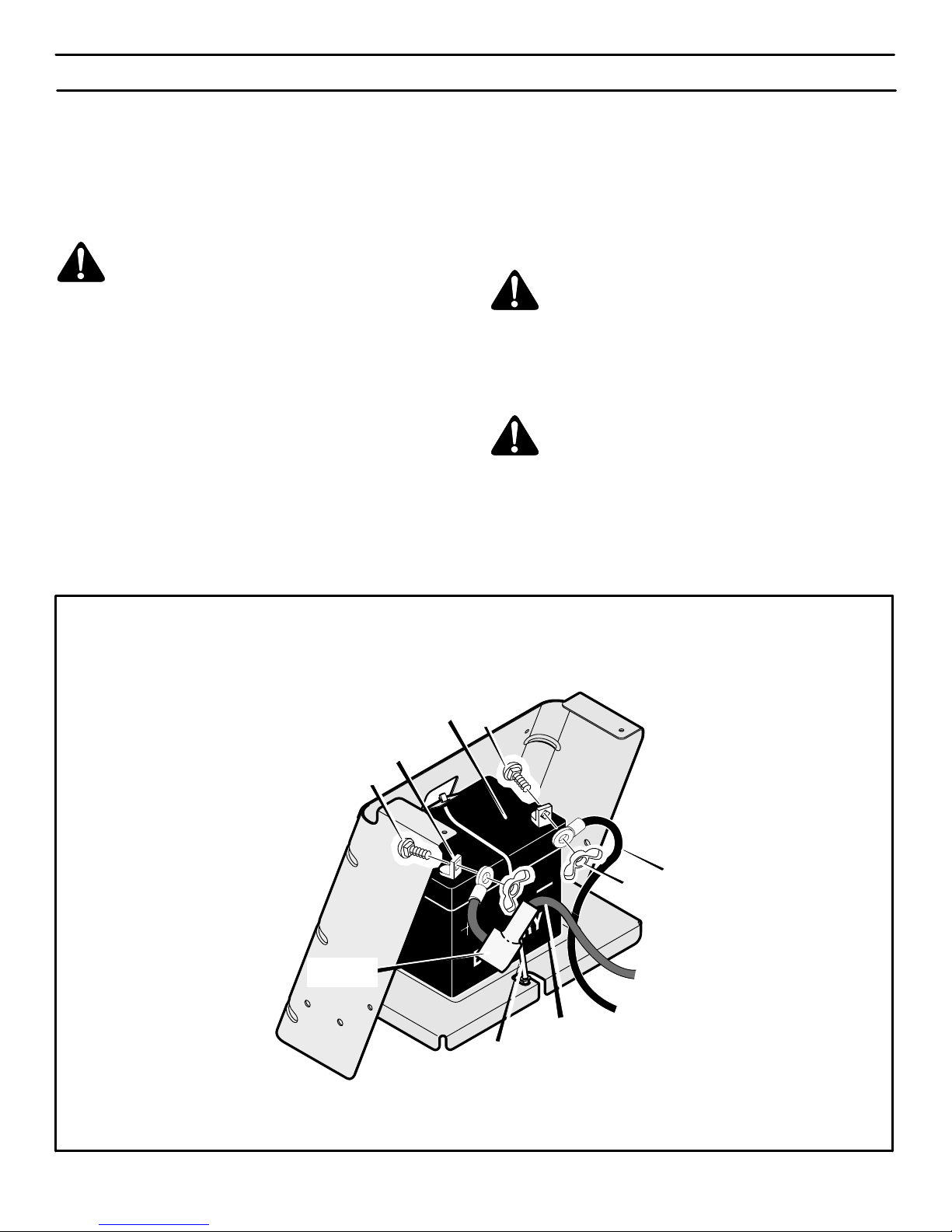
MANTENIMIENTO
89
BATERÍA LIBRE DE MANTENIMIENTO
CÓMO DESMONTAR LA BATERÍA
Si necesita cambiar o limpiar la batería, desmóntela de la siguiente
manera.
ADVERTENCIA. Para evitar que se produzcan chispas, desconecte el cable negro de la batería del borne
negativo (−) antes de desconectar el rojo.
ADVERTENCIA. La batería contiene ácido sulfúrico
dañino para la piel, los ojos y la ropa. Si el ácido toca
el cuerpo o la ropa, lávese con agua.
1. Desconecte el cable negro del borne negativo (−)
(Figura 66).
2. Desconecte el cable rojo del borne positivo (+).
3. Empuje el extremo inferior de la abrazadera de la batería para
desconectarla de la bandeja.
4. Desmonte la batería desde el lado derecho de la unidad.
CÓMO LIMPIAR LA BATERÍA
1. Desmonte la batería.
2. Lávela con un galón de agua mezclada con cuatro cucharadas
de bicarbonato de soda. No deje que el agua entre en los elementos de la batería.
3. Limpie los bornes y los extremos de los cables con un cepillo
para cables.
4. Instale la batería.
5. Aplique grasa a los bornes para prevenir la corrosión.
CÓMO CARGAR LA BATERÍA
ADVERTENCIA. No fume mientras carga la batería.
No deje que le lleguen chispas. Los gases del ácido
de la batería podrían provocar una explosión.
1. Antes de cargar la batería tiene que desmontarla.
2. Use un cargador de 12 voltios para baterías. Cárguela a una
velocidad de 6 amperios por 1 hora.
3. Instale la batería.
ADVERTENCIA: Para evitar que se produzcan chispas, conecte el cable rojo al borne positivo (+) antes
de conectar el negro.
4. Conecte el cable rojo al borne positivo (+) con los sujetado-
res, como se muestra.
5. Monte el manguito protector de la batería al borne positivo
(+).
6. Conecte el cable negro al borne negativo (−) con los sujetadores, como se muestra.
B
A
Borne positivo (+)
Cable negro
Abrazadera
A
Batería
Cable rojo
Figura 66
Manguito
protector
400150
Page 90
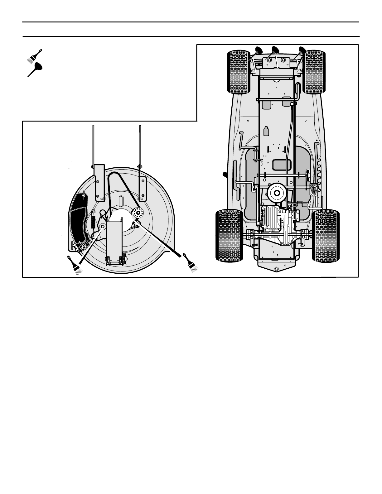
MANTENIMIENTO
90
DÓNDE LUBRICAR
Aplique grasa con un cepillo a las áreas mostradas.
Lubrique con aceite de motor las áreas mostradas.
NOTA: Aplique grasa al ensamblado del mecanismo de
dirección.
PRECAUCION: Si la unidad se opera en áreas áridas donde
hay arena, utilice polvo de grafito seco para lubricar la unidad.
Figura 67
400150
Page 91
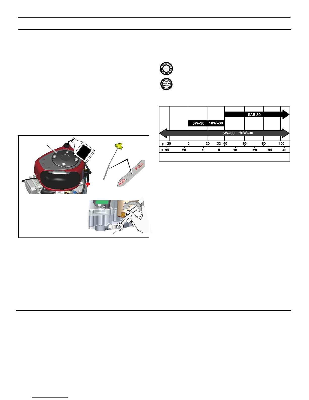
MANTENIMIENTO
91
MOTOR
CÓMO REVISAR EL ACEITE
NOTA: No revise el nivel del aceite mientras que el motor esté
en marcha.
1. Asegúrese de que la unidad esté nivelada.
2. Limpie el área alrededor de la varilla indicadora de nivel de
aceite (Figura 68). Retire la varilla indicadora. Limpie el aceite de la varilla indicadora.
3. Inserte la varilla indicadora en el tubo para agregar aceite. Gi-
re la varilla hacia la derecha hasta que esté apretada. Retire
la varilla. Revise el nivel del aceite en la varilla indicadora. El
nivel de aceite debe alcanzar hasta la marca FULL (lleno) en
esta varilla.
4. Si sea necesario, agregue aceite hasta que el aceite alcance
hasta la marca FULL en la varilla indicadora. La cantidad de
aceite necesaria desde ADD (agregar) a FULL se muestra en
la varilla indicadora. No agregue demasiado aceite.
Dipstick
Air Screen
Varilla
indicadora
Figura 68
Tapa de drenaje de aceite
Malla de filtro
de aire
CÓMO CAMBIAR EL ACEITE
NOTA: No drene aceite de un motor frío. Antes de drenar el
aceite, deje que el motor funcione durante varios minutos.
Asegúrese de no derramar aceite en las correas.
1. Con el motor APAGADO pero todavía caliente, coloque la unidad de manera que el motor quede bien nivelado y desconecte
el cable de la bujía.
2. Retire la tapa de drenaje de aceite. Drene todo el aceite del
motor. Instale y apriete la tapa de drenaje de aceite.
3. Utilice solamente un aceite con detergente de alta calidad, valorado
con la clasificación SG, SH, SJ o SL de servicio API. Seleccione
el grado de viscosidad SAE del aceite de acuerdo con la temperatura operativa anticipada, utilizando la tabla de temperaturas a continuación:
NOTA: El aceite sintético que cumpla con ILSAC GF-2 y
que tenga la marca de certificación API y el símbolo de
servicio API (que aparece a la izquierda) con “SJ/CF
ENERGY CONSERVING” o mayor, es un aceite aceptable para todas las temperaturas. El uso de aceite sintéti-
co no altera los requisitos de los intervalos para el
cambio de aceite.
Grados de viscosidad SAE requeridos
Sintético
**
*
TABLE DE TEMPERATURAS
* PRECAUCIÓN: Los motores enfriados por aire se calientes más
que los motores automotrices. El uso de aceites no sintéticos
multiviscosidad (5W-30, 10W-30, etc.) en temperaturas sobre
los 40_ F (4_ C) resultará en un consumo de aceite mayor que
lo normal. Cuando use aceite multiviscosidad, revise con
frecuencia el nivel del aceite.
** PRECAUCIÓN: Si se usa aceite SAE 30 en temperaturas
menores que 40_ F (4_ C), resultará en arranques más difíciles
y en posible daño de perforación al motor debido a una
lubricación inadecuada.
NOTA: Aunque los aceites de multiviscosidad (5W30, 10W30,
etc.) mejoran el arranque en un clima frío, estos resultarán en
más consumo del aceite cuando se usan en temperaturas
superiores a 32
0
F. Revise el nivel de aceite del motor más
frecuentemente para evitar la posibilidad de dañar el motor
debido a la falta de aceite.
4. Limpie el área alrededor de la varilla indicadora del nivel de
aceite. Retire la varilla del tubo para agregar aceite. Lenta-
mente vierta aproximadamente 48 onzas (3 pintas) de aceite
en el tubo.
5. Inserte la varilla indicadora del nivel de aceite en el tubo para
agregar aceite. Gire la varilla hacia la derecha hasta que esté
bien apretada. Retire la varilla y revise el nivel de aceite indicado. El nivel de aceite debe alcanzar hasta la marca FULL en la
varilla indicadora.
CÓMO LIMPIAR EL SISTEMA DE ENFRIAMIENTO
El motor es enfriado por aire. El aire que enfría el motor entra por la
malla de filtro de aire encima del motor. Limpie el malla de filtro de
aire cada 100 horas de funcionamiento o cada año, cumpliendo los
pasos siguientes.
1. Retire todo césped, tierra, o escombro de la malla de filtro de
aire, usando una tela o un cepillo (Figura 68).
2. Inspeccione el borde de la cubierta del motor por si hay césped o escombros. Retire cualquier césped o escombros visibles al borde inferior de la cubierta del motor.
CÓMO REVISAR EL SILENCIADOR
Revise el silenciador cada 50 horas. Asegúrese de que el
silenciador esté montado correctamente y que no esté flojo. Si el
silenciador está gastado o quemado, reemplácelo con un
silenciador nuevo. Un silenciador gastado es un riesgo de incendio
y también puede dañar el motor.
Si le ha conectado una rejilla parachispas al silenciador, revise
también la rejilla parachispas cuando revisa el silenciador. Si la
rejilla parachispas está gastada o dañada, reemplácela con una
rejilla parachispas nueva que puede comprar en su Centro de
Servicio Sears más cercano.
400150
Page 92
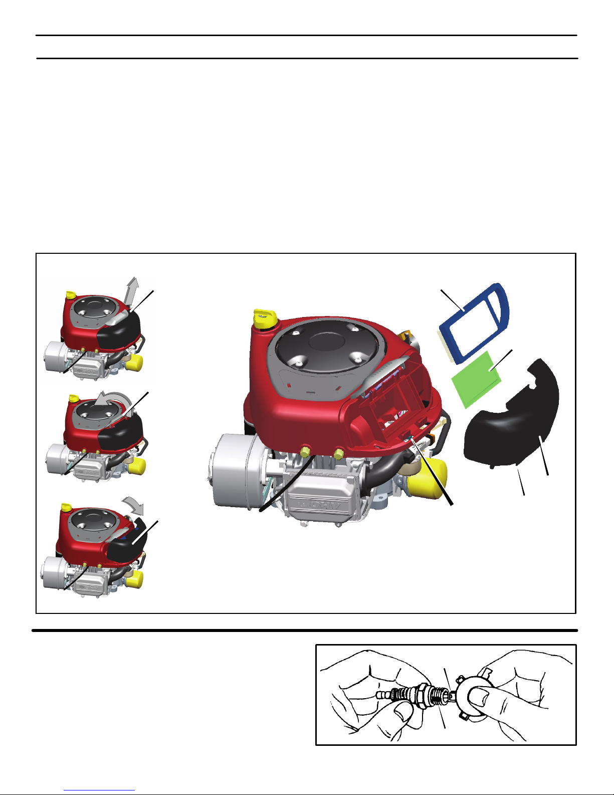
MANTENIMIENTO
92
CÓMO SERVICIO LOS FILTROS DE AIRE
NOTA: Nunca ponga en marcha un motor sin los filtros de aire
(portafiltro, filtro). Los filtros de aire ayudarán a proteger el
motor contra el deterioro. Para el tamaño de un filtro de
repuesto, consulte la lista de partes para el motor.
PRECAUCIÓN: No use aire presurizado ni solventes para
limpiar el portafiltro. El aire presurizado puede dañar el
portafiltro; los solventes lo disolverán.
Si el filtro de aire está marcado con la palabra
WASHABLE/LAVABLE, éste se puede lavar con agua tibia y un
detergente suave.
IMPORTANTE: Enjuague en agua de la llave con el lado de la
MALLA hacia arriba para que salga el polvo y la suciedad. Deje
que el filtro se seque durante la noche antes de reinstalarlo.
Para sacar / instalar el portafiltro
1. Tire de la manija para la cubierta del filtro de aire. Levante vol-
teando la manija hacia el motor (Figura 69).
2. Retire la cubierta
.
3. Levante con cuidado el portafiltro y el filtro, si es parte del
equipo, del cárter de la sopladora.
4. Para prevenir que caiga basura en el carburador, limpie la base
del filtro de aire
.
5. Instale un filtro de aire, si es parte del equipo, y un portafiltro
nuevos firmemente en la base para el filtro de aire.
6. Alinee las lengüetas de la cubierta con las ranuras del cárter
de la sopladora e instale la cubierta.
7. Para sujetar la cubierta, mueva la manija hacia delante y empújela hacia abajo.
Figura 69
Tirar la manija
Levantar volteando
la manija
Quitar la cubierta
Portafiltro
Filtro
Ranuras
Cubierta
Lengüetas
CÓMO REVISAR LA BUJIA
1. Revise la separación de la bujía con un calibrador de separa-
ciones (Figura 70). La separación correcta es de 0,030”.
2. Para un arranque fácil y buen rendimiento, reemplace la bujía
cada estación o cada 100 horas de uso.
Calibrador de separaciones
0.030”
Figura 70
Bujía
400150
Page 93
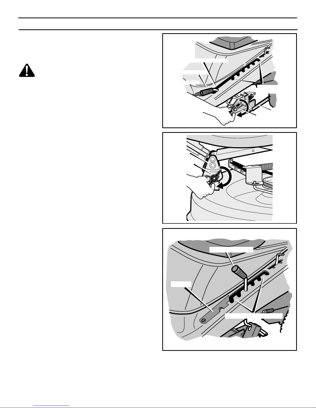
SERVICIO Y AJUSTE
93
CÓMO NIVELAR EL CÁRTER
Para que la cuchilla corte con facilidad y el césped tenga mejor
aspecto es necesario que el cárter del cortacésped esté nivelado.
ADVERTENCIA. Antes de inspeccionar, ajustar o reparar la unidad, desconecte el cable de la bujía. Esto
se hace para evitar que el motor arranque por accidente.
1. Estacione la unidad sobre una superficie plana.
2. Revise la presión de los neumáticos. Si es incorrecta, el cárter
no cortará de manera uniforme. La presión de aire correcta
aparece indicada en la cara lateral de los neumáticos.
3. Mueva el control de rotación de la cuchilla a la posición DE-
SENGANCHE.
4. Abra la cubierta (Figura 71).
5. Ponga la palanca de elevación en la posición de AJUSTE DE
NIVEL (Figura 71).
6. Afloje la perilla de ajuste trasera y delantera (Figure 27 y
Figura 72). Verifique que ambos lados del cárter estén sobre
una superficie nivelada.
7. Asegúrese de que la placa de ajuste esté suelta y se pueda
mover fácilmente hacia arriba y hacia abajo (Figure 28).
8. Apriete la perilla de ajuste delantera y trasera. Apriételas bien.
Puede usar una llave si es necesario. Apríetelas a un par de
torsión de 10 pies−libra (13,5 N−m).
9. Levante la palanca de elevación desde la posición de AJUS-
TE DE NIVEL hasta la posición de ALTURA DE CORTE
(Figura 73).
10. Cierre la cubierta.
11. Reconecte el cable a la bujía.
12. Corte un tramo corto del césped. Si la altura de corte no es uniforme, repita los pasos anteriores.
PRECAUCIÓN: No opere la unidad con el cárter en la posición
de AJUSTE DE NIVEL. Si lo hace, el cárter y las cuchillas del
cortacésped pueden resultar dañados.
Figura 71
Posición de ajuste de nivel
Posiciones de
altura de corte
Cubierta
Palanca de elevación
Perilla de ajuste trasera
Soporte
Figura 72
Perilla de ajuste
delantera
Placa de
ajuste
Figura 73
Posiciones de altura de corte
Cubierta
Palanca de elevación
400150
Page 94
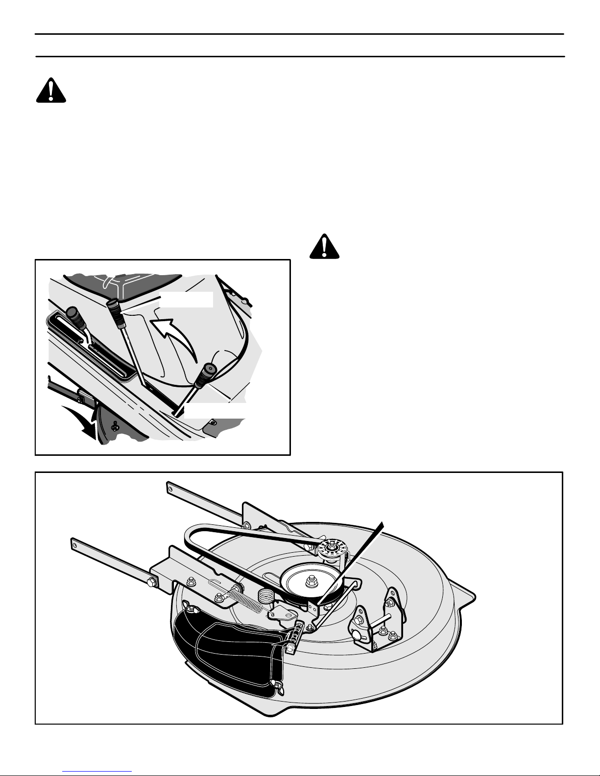
SERVICIO Y AJUSTE
94
CÓMO AJUSTAR EL EMBRAGUEDE ADITAMENTO
ADVERTENCIA: El embrague de aditamento tiene
que funcionar correctamente para evitar lesiones.
En condiciones normales de uso, no necesitará ajustar el
embrague de aditamento. Sin embargo, si el cortacésped
empieza a funcionar mal y la calidad del corte no es buena, puede
hacer lo siguiente.
1. Siempre que vaya a segar el césped, el control de gases tiene
que estar en la posición RÁPIDO.
2. Ponga el embrague de aditamento en la posición de
DESEMBRAGUE (Figura 74).
3. Detenga el motor. Desconecte el cable de la bujía.
Posición de embrague del
embrague de aditamento
Posición de
desembrague
Figura 74
4. Revise las cuchillas. Asegúrese de que estén bien afiladas. Si
no lo están, las puntas del césped se secarán.
5. Si aún así el corte no mejora, cambie la correa de transmi−
sión. Consulte “Cómo cambiar la correa de transmisión del
cortacésped”. Si esto no corrige el problema, lleve la unidad a
un Centro de Servicio Sears u otro centro de servicio
cualificado.
6. Ponga el embrague de aditamento en la posición de
DESEMBRAGUE. Detenga el motor. Desconecte el cable de
la bujía.
7. Revise el freno de la cuchilla. Gire la polea con la mano. La
zapata del freno tiene que estar presionada a fondo contra la
polea (Figura 75).
ADVERTENCIA: Si la zapata del freno no está presionada a fondo contra la polea, lleve la unidad a un Centro de Servicio Sears u otro centro de servicio cualificado.
8. Ponga el embrague de aditamento en la posición de EMBRAGUE.
9. Revise la zapata del freno de la cuchilla. Si está demasiado
desgastada o estropeada, cambie los ensamblajes de la zapa-
ta. Encontrará las piezas de repuesto correctas y la asistencia
que necesite en un Centro de Servicio Sears.
10. Conecte el cable a la bujía. Siegue un trozo pequeño y vuelva
a comprobar el funcionamiento del embrague de aditamento.
11. Cuando ponga el embrague de aditamento en la posición de
DESEMBRAGUE, todo se debería parar en unos cinco segundos. Si la correa o las cuchillas siguen girando y la correa de
transmisión es nueva, embrague y desembrague el embrague de aditamento cinco veces para eliminar el exceso de
caucho. Si necesita asistencia, lleve el cortacésped a un Centro de Servicio Sears u otro centro de servicio cualificado.
Figura 75
Freno de la cuchilla
(zapata contra la polea)
400150
Page 95
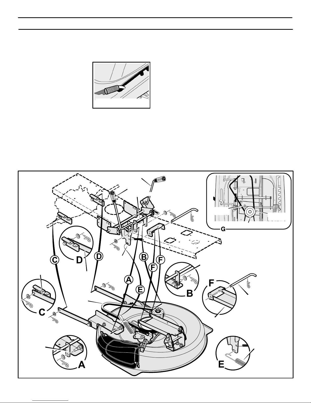
Posición de
ajuste de nivel Figura 76
SERVICIO Y AJUSTE
95
CÓMO DESMONTAR EL CÁRTER
1. Mueva el embrague de aditamento a la posición de DESEMBRAGUE.
2. Coloque la palanca de elevación en la posición de ajuste de
nivel (Figura 76).
NOTA: La palanca de
elevación tiene que estar
bloqueada en la posición de
AJUSTE DE NIVEL.
3. Quite los pasadores abiertos y
las arandelas de las mordazas
traseras (Figura 77). Vea las
ilustraciones C y D.
4. Quite los pasadores abiertos y las arandelas de los eslabones
de suspensión. Vea las ilustraciones A y B.
5. Desconecte el resorte de extensión de la varilla de control
de la cuchilla. Vea la ilustración E.
6. Desconecte la silleta delantera del soporte del armazón. Vea
la ilustración F.
7. Separe la correa de transmisión del cortacésped de la po-
lea doble. Vea la ilustración G.
8. Saque el cárter desde el lado derecho de la unidad.
9. Si usa la unidad sin el cárter, mueva la palanca de elevación a
la posición MÁS ALTA.
CÓMO INSTALAR EL CÁRTER
1. Empuje el cárter por debajo del lado derecho de la unidad.
2. Ponga la correa de transmisión alrededor de la polea doble.
El lado en forma de “V” de la correa de transmisión tiene que
estar en contacto con la polea doble. Verifique que la correa
de transmisión no esté retorcida.
3. Conecte la silleta delantera al soporte del armazón con la va-
rilla de la silleta. Fíjela con los sujetadores como se indica.
Vea la ilustración F.
4. La correa de transmisión tiene que estar entre la polea doble
y las dos guías de la correa. Vea la ilustración G.
5. Conecte los eslabones de suspensión con el ensamblado
del elevador. Sujételos con las arandelas y los pasadores
abiertos. Vea las ilustraciones A y B.
6. Conecte las mordazas traseras a los soportes de suspensión.
Sujételas con las arandelas y los pasadores abiertos. Vea las
ilustraciones C y D.
7. Conecte el resorte de extensión a la varilla de control de la
cuchilla. Vea la ilustración E.
8. Mueva el embrague de aditamento a la posición de DESEM-
BRAGUE. La correa de transmisión tiene que quedar dentro
de las guías y por debajo del tubo separador.
9. Verifique que el cárter esté nivelado. Consulte “Cómo nivelar
el cárter”.
10. Compruebe el funcionamiento del embrague de aditamento.
Consulte “Cómo ajustar el embrague de aditamentos”.
Ensamblado
del elevador
Embrague de
aditamentos
Varilla de la silleta
Correa de
transmisión
Palanca de elevación
Figura 77
Resorte de
extensión
Resorte de
suspensión
Brazo regulador
Brazo regulador
Guía de la
correa
Polea doble
Eslabón de
suspensión
Guía de la
correa
Silleta delantera
Tubo separador
400150
Page 96
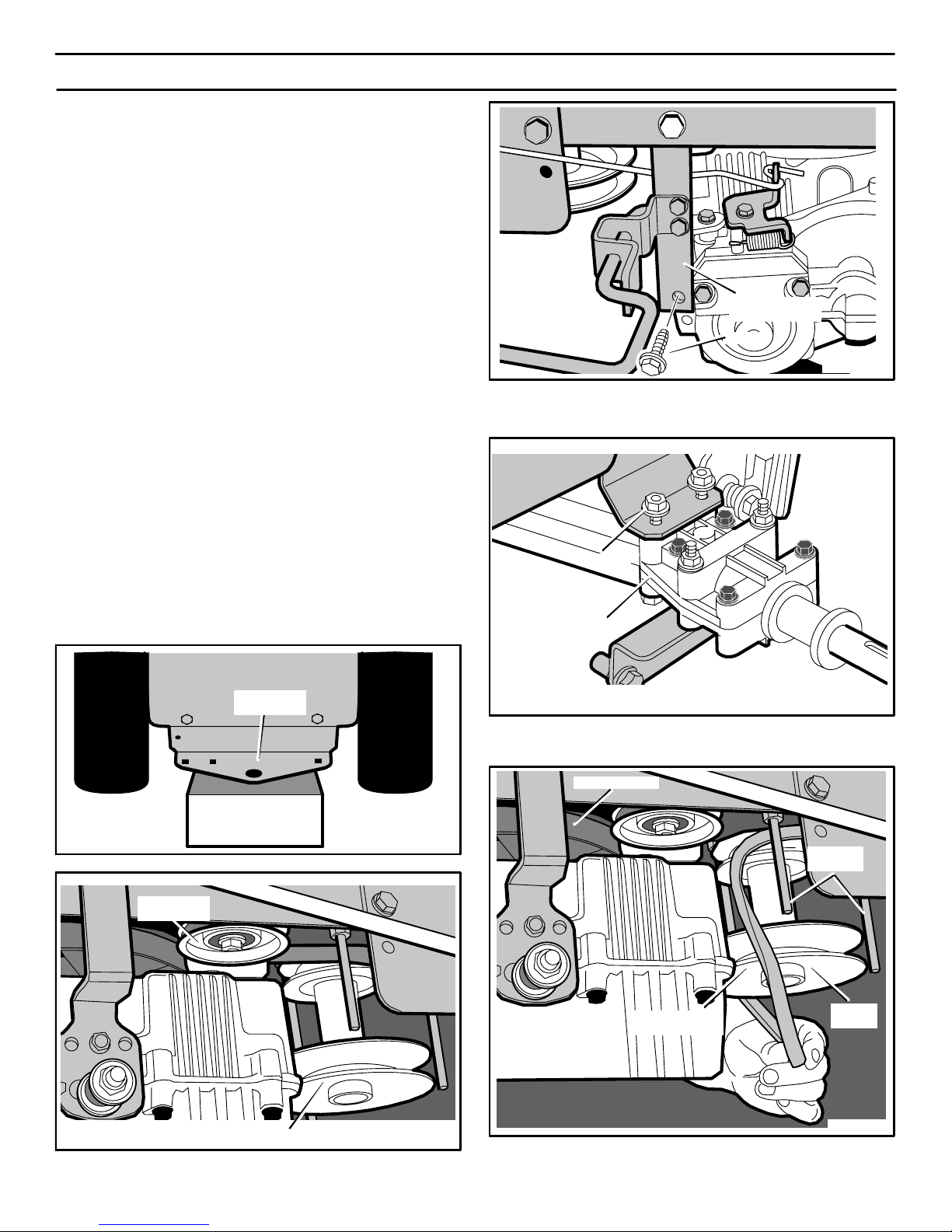
SERVICIO Y AJUSTE
96
CÓMO REEMPLAZAR LAS
CORREA DE PROPULSIÓN
REMOCIÓN DE LA CORREA
DE PROPULSIÓN DEL MOTOR
1. Desmonte el cárter del cortacésped. Consulte las
instrucciones en la sección “Cómo desmontar el cárter del
cortacésped“.
2. Coloque el enganche trasero sobre un bloque de 10 a 12
pulgadas. El bloque debe ser suficientemente alto para
levantar las ruedas traseras del suelo (Figura 78).
3. Saque las ruedas traseras.
4. Saque la polea tensora (Figura 79).
5. Retire la perno de la abrazadera de torsión (Figura 80).
6. Afloje las tuercas de cada lado de la transmisión (Figura 81).
No saque las tuercas. Aflójelas hasta que las tuercas queden
en la parte de arriba de los pernos.
7. Deslice la parte posterior de la correa de propulsión por
encima de la polea motriz y que salga por delante de la
transmisión. Luego, jale la correa de propulsión hacia abajo
entre las guías de correa y la polea doble (Figura 82).
8. Para instalar, invierta los pasos anteriores.
9. Instale el cárter del cortacésped. Consulte las instrucciones en
“Cómo instalar el cárter del cortacésped“.
10. Revise la operación del sistema de transmisión. Consulte
“Cómo revisar y ajustar el embrague“ y también “Cómo ajustar
la palanca de control de velocidades”.
Figura 78
Bloque de 10 a 12
pulgadas de alto
Enganche
trasero
Figura 79
Polea doble
Polea
tensora
Figura 80
Abrazadera de
torsión
Perno
Figura 81
Tuerca
Transmisión
Figura 82
Polea motriz
Correa de
propulsión
Polea
doble
Guía de
correa
400150
Page 97
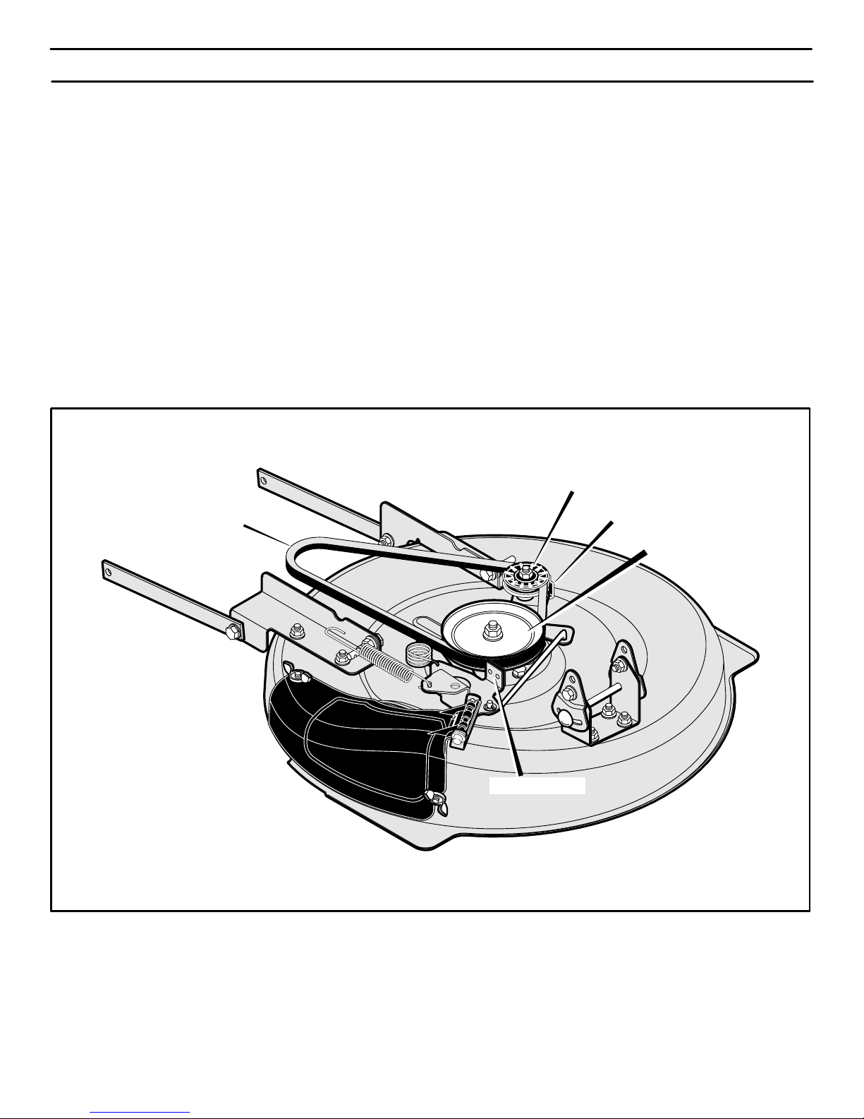
SERVICIO Y AJUSTE
97
CÓMO CAMBIAR LA CORREA DE TRANSMISIÓN DEL CORTACÉSPED
1. Desmonte el cárter del cortacésped. Consulte “Cómo desmontar el cárter”.
2. Separe el retenedor de la correa de la polea tensora y saque
la correa de transmisión (Figura 83).
3. Separe la zapata del freno de la polea del eje intermedio y
saque la correa de transmisión del cortacésped.
NOTA. Reemplace la correa de transmisión con una correa
original adquirida en un Centro de Servicio Sears.
4. Instale la correa de transmisión nueva. Separe la zapata del
freno de la polea del eje intermedio. Coloque la correa de
transmisión alrededor de la polea del eje intermedio.
5. Separe el retenedor de la correa de la polea tensora. Colo-
que la correa de transmisión alrededor de la polea tensora.
6. El lado en forma de “V” de la correa de transmisión tiene que
tocar la polea del eje intermedio y la polea tensora.
7. Instale el cárter del cortacésped. Consulte “Cómo instalar el
cárter”.
8. Antes de empezar a cortar el césped, revise el ajuste del embrague de aditamentos. Consulte “Cómo ajustar el embrague
de aditamentos”.
Figura 83
Correa de transmisión del cortacésped
Retenedor de la correa
Zapata del freno
Polea tensora
Polea del eje intermedio
400150
Page 98
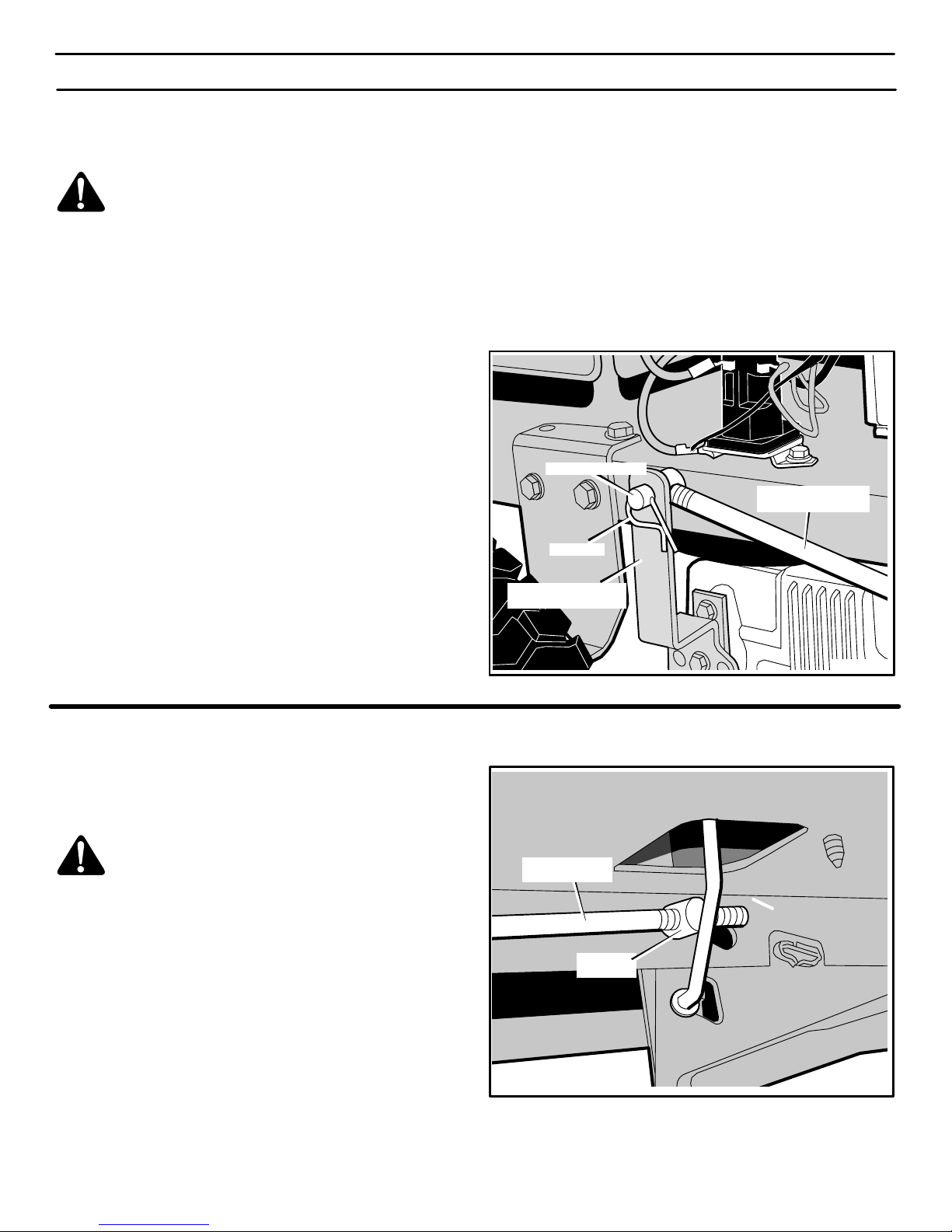
SERVICIO Y AJUSTE
98
CÓMO AJUSTAR LA PALANCA
DE CONTROL DE VELOCIDADES
ADVERTENCIA: Antes de inspeccionar, ajustar o reparar la unidad, desconecte el cable de la bujía. Esto
se hace para evitar que el motor arranque por accidente.
Puede ser necesario un ajuste de la palanca de control de
velocidades si la correa de transmisión se gasta o después de
instalar una correa de transmisión nueva, Cuando la palanca de
control de velocidades se mueve a la posición NEUTRO, la unidad
debe detenerse por completo. Si la unidad no se detiene
completamente, realice los ajuste de la manera siguiente.
1. Mueva la palanca de control de velocidades a la posición NEUTRO.
2. Retire la chaveta de la tuerca ajustable (Figura 84).
3. Desconecte la tuerca ajustable del brazo accionador hidros-
tático.
4. Si la unidad avanzaba lentamente cuando la palanca de control
de velocidades estaba en la posición NEUTRO, entonces gire
la tuerca ajustable hacia la derecha (hacia adelante, una o dos
vueltas. Esto acortará la longitud de la varilla de control de ve-
locidad.
5. Si la unidad se movía lentamente hacia atrás cuando la palanca de control de velocidades estaba en la posición NEUTRO,
entonces gire la tuerca ajustable hacia la izquierda (hacia
atrás), una o dos vueltas. Esto alargará la longitud de la varilla
de control de velocidad.
6. Monte la tuerca ajustable al brazo accionador hidrostático
y fíjela con con la chaveta.
7. Reconecte el cable a la bujía. Encienda el motor, y dé una vuelta de prueba con la unidad. Asegúrese de que la unidad se detenga completamente cuando se coloca la palanca de control
de velocidades en la posición NEUTRO.
Brazo accionador
hidrostático
Varilla de control
de velocidad
Tuerca ajustable
Chaveta
Figura 84
CÓMO REVISAR Y AJUSTAR EL EMBRAGUE
Si la correa de transmisión está suelta, el embrague patinará
cuando; (1) suba una cuesta, (2) remolque una carga pesada o (3)
la unidad no avanzará. Ajuste el embrague de la manera siguiente.
ADVERTENCIA: Antes de inspeccionar, ajustar o reparar la unidad, desconecte el cable de la bujía. Esto
se hace para evitar que el motor arranque por accidente.
1. Retire la chaveta y la arandela de la tuerca ajustable en la varilla de embrague (Figura 85).
2. Gire la tuerca ajustable hacia la derecha (hacia adelante) pa-
ra incrementar el movimiento del pedal y apretar la correa.
3. Monte la tuerca ajustable y fíjela con la arandela y la chaveta.
4. Reconecte el cable a la bujía. Encienda el motor y dé una vuelta de prueba a la unidad. Asegúrese de que ni el embrague ni
la correa patinen.
5. Si la correa sigue deslizándose después de haber ajustado el
embrague, significa que está desgastada o estropeada y
tendrá que cambiarla. Consulte “Cómo reemplazar las correa
de propulsión”.
Tuerca
ajustable
Varilla de
embrague
Figura 85
400150
Page 99
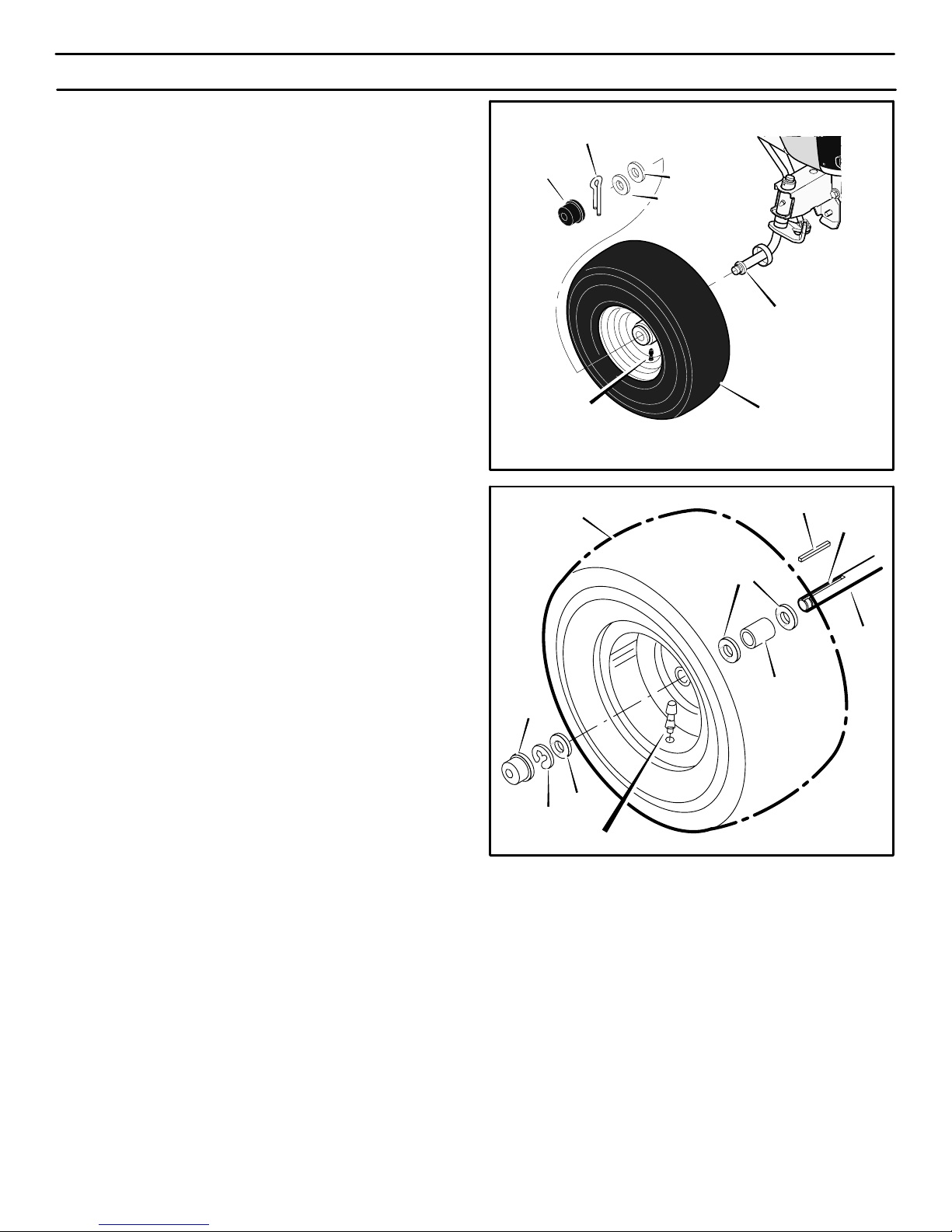
SERVICIO Y AJUSTE
99
CÓMO INSTALAR LAS RUEDAS
Si necesita sacar las ruedas, vuelva a instalarlas de la siguiente
manera.
Rueda delantera
1. El vástago de válvula tiene que quedar hacia la parte exterior
del tractor. Deslice la rueda delantera en la mangüeta.
(Figura 86).
2. Sujete la rueda delantera con la arandela y la chaveta. Sepa-
re los extremos de la chaveta para sujetar la rueda a la man-
güeta.
3. Si el modelo lleva tapacubos, no deje de instalarlos. Verifique
que la arandelas está sujetándolos en su sitio.
Rueda trasera
1. Instale las arandelas y el separador en el eje como se muestra en la Figura 87.
2. Monte la llave cuadrada en la ranura de la llave (Figura 87).
3. El vástago de válvula tiene que quedar en la parte exterior del
tractor. Alinee la ranura de la rueda trasera con la llave cua-
drada. Deslice la rueda trasera en el eje.
4. Sujete la rueda trasera con la arandela y el anillo “e”.
5. Si el modelo lleva tapacubos, no deje de instalarlos. Verifique
que la arandelas está sujetándolos en su sitio.
Figura 86
Rueda delantera
Mangüeta
Vástago de
válvula
Arandela
Arandela
Tapacubos
Chaveta
Figura 87
Anillo “e”
Arandela
Tapacubos
Arandela
Separador
Llave cuadrada
Vástago de válvula
Ranura
de la llave
Eje
Rueda trasera
400150
Page 100
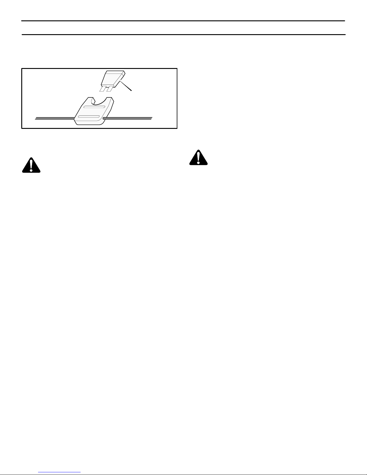
SERVICIO Y AJUSTE
100
CÓMO REEMPLAZAR EL FUSIBLE
Si el fusible está fundido, no se encenderá el motor. La ubicación
del fusible está al lado de la batería. Quite el fusible y reemplácelo
con un fusible de tipo automotriz de 15 amperios (Figura 88).
Figura 88
Fusible de tipo automotriz
de 15 amperios
CÓMO LIMPIAR EL CÁRTER DE LA
CORTADORA DE CÉSPED
ADVERTENCIA: Antes de limpiar el cárter del cortacésped , pare el motor y desconecte el cable a la bujía.
La hierba y otros escombros encima del cárter del cortacésped
pueden impedir el funcionamiento correcto de la correa. Para
seguridad y operación correcta, limpie la parte superior del cárter
con frecuencia. Quite la hierba y los escombros de las poleas y de
otras partes móviles.
1. Mueva la palanca para el embrague de aditamentos a la
posición de EMBRAGUE.
2. Limpie la parte superior del cárter.
3. Mueva la palanca del embrague de aditamentos a la posición
de DESEMBRAGUE.
4. Limpie de nuevo la parte superior del cárter.
5. Después de cortar el césped, limpie la parte inferior del cárter.
ALINEACIÓN DE LAS RUEDAS DELANTERAS
No se puede ajustar la alineación de las ruedas delanteras. Si el
mecanismo de dirección está dañado y ha cambiado la alineación,
lleve la unidad a su Centro de Servicio Sears más cercano.
ALMACENAMIENTO (por más de 30 días)
Al final de cada año, prepare la unidad para almacenamiento de la
siguiente manera.
INSPECCIÓN GENERAL
1. Inspeccione las correas. Si están dañadas o gastadas,
reemplácelas con piezas de repuesto de fábrica. Consulte las
instrucciones sobre los repuestos de correas en la sección de
Servicio y Ajuste.
2. Asegúrese que todas las tuercas, los pernos, y los tornillos
estén bien apretados. Inspeccione las partes móviles para ver
si están dañadas, si tienen grietas, o si están gastadas.
Reemplácelas según sea necesario.
CÁRTER DEL CORTACÉSPED
1. Limpie el cárter del cortacésped. Consulte “Cómo limpiar el
cárter del cortacésped”.
LUBRICACIÓN DE LA UNIDAD
Vea las instrucciones sobre “Dónde lubricar” en la sección de
Mantenimiento.
MOTOR
1. Limpie la tierra y la hierba del motor.
2. Cambie el aceite. Consulte las instrucciones sobre “Cómo
cambiar el aceite”.
3. Examine el filtro de aire. Consulte las instrucciones sobre
“Cómo limpiar el sistema de enfriamiento”.
4. Inspeccione la bujía. Consulte las instrucciones sobre “Cómo
revisar la bujía”.
SISTEMA DE ALIMENTACIÓN DE COMBUSTIBLE
ADVERTENCIA: No drene la gasolina de la cortadora dentro de un edificio ni cerca de un fuego. No fume porque los vapores del combustible podrían
causar una explosión.
Durante el almacenaje de la unidad, es importante prevenir la
formación de depósitos de resinas en partes esenciales del sistema
de combustible tales como el carburador, el filtro de combustible, el
conducto o el tanque de combustible. Además, es importante saber
que los combustibles mezclados con alcohol (llamados gasohol o
aquellos que contienen etanol o metanol) pueden atraer humedad
que puede producir la separación y la formación de ácidos durante
el almacenaje de la unidad. El combustible que contiene ácidos
puede dañar el sistema de combustible de un motor mientras se
encuentra almacenado.
NOTA: Un estabilizador de combustible (como STA−BIL) es
una alternativa aceptable para reducir la formación de resinas
en el tanque de combustible y el recipiente para guardar
gasolina. Siempre respete las proporciones indicadas en el
recipiente del estabilizador. Deje el motor en marcha durante
por lo menos 3 minutos después de agregar el estabilizador
para permitir que el estabilizador llegue al carburador. No
drene el tanque de combustible y el carburador si se utiliza
estabilizador.
Si no utiliza un estabilizador, haga lo siguiente:
1. Encienda el motor.
2. Deje el motor en marcha hasta que el tanque de combustible
y el carburador no tengan combustible y el motor se apague.
3. No deje combustible en el tanque de combustible o en el
carburador. El combustible puede dañar la función del sistema
de alimentación de combustible.
4. Después del almacenamiento, asegúrese de utilizar
combustible fresco.
BATERIA
1. Retire la batería.
2. Limpie cualquier depósito en los bornes de la batería.
3. Cargue la batería. Consulte las instrucciones sobre “Cómo
revisar y cargar la batería”.
4. Guarde la batería en un lugar fresco y seco.
NOTA: Después de un largo período de almacenamiento,
cargue la batería.
400150
 Loading...