

Craftsman 502255193 Owner’s Manual
o_vne
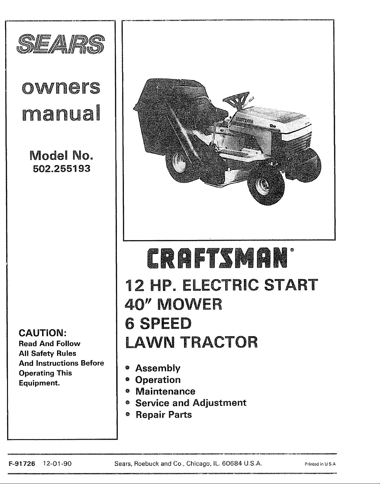
Model No.
502.255193
1
, ,i i iil,ii
CAUTION:
Read And Follow
All Safety Rules
And Instructions Before
Operating This
Equipment.
12 HP. LECTRIC
40" MOWER
SPEED
LAWN TRACTOR
® Assembly
o Operation
e Maintenance
e Service and Adjustment
® Repair Parts
START
F-91726 12-01-90 Sears, Roebuck and Co, Chicago, IL 60684 UoS.A. PrintedinUSA

SAFETY RULES
Safe Operation Practices for Riding Vehicles
As Recommended by American National Standards Institute
This cutting machine is capable of amputating hands and feet and throwing objects. Failure to observe the following
safety instructions could result in serious injury or death to the operator or bystanders.
GENERAL OPERATION:
1o Read, understand, and follow all instructions in the instruction Book, on the machine, on the engine, and with any attachments
before starting_
2 Only aliow responsible adults familiar with the instructions to operate the machine.
3.. Clear the area of objects such as rocks, toys, wire, etc_ which could be picked up and thrown by the b|adav
4o Be sure the area is clear of other people before mowing. Stop the machine if anyone enters the area°
5. Never carry passengers.
6. Disengage all attachment ctutches and shift into Neutral before attempting to start the engine_
7,_ Disengage power to the mower or any attachments before backing up. Do not mow in reverse untess absolutely necessary. Always
look down and behind before and while backing.
8. Be aware of the directlon the mower discharge_ Do not point discharge from the mower at anyone or at places where people may bee Do
not operate the mower without either the entire grass bagger or the mower guard in place,
9. Slow down before turning.
100 Never leave a machine unattended with the engine running, Always disengage the blade(s), set the parking brake, stop the engine and
remove the key before dismounting
11, Disengage power to attachment(s) when transporting or not {n use,, Disengage the blade(s) when not mowing°
12. Stop the engine before removing the grass bagger or unclogging the chute.
13. Mow only in daylight orgood artificial light,
14. Do not operate the machine while under the influence of alcohol or drugs or when very tired,,
15,. Watch for traffic when operating near or crossing roadways,
16. Use extra caution when loading or unloading the machine when using a trailer or truck for transporting.
17,. Always wear safety glasses or an eye shield when you operate the unit to protect your eyes from foreign objects that can be thrown
/
from the unit, Aiways wear eye protection when you make an adjustment or repair to the machine,
18, Use care when puliing loads or using heavy equipment°
ao Use oniy approved drawbar hitch points.
b., Limit loads to those you can safely control
c. Do not turn sharply,. Use care when backing.
d. Use counterweights or wheel weights when suggested in the Instruction Book.
CHILDREN:
Tragic accidents can occur if the operator isnot alert to the presence of children, Children are often attracted to the machine and the
mowing activity. Never assume that children will remain where you last saw them,
1. Keep children out of the mowing area and in the watchful care of an adult other than the operator.
2, Be alert and turn the engine off if children enter the area.
3 Before and when backing, look behind and down for small children,
4. Never carry children or any passengers They may fall off and be seriously injured or interfere with the safe operation of the
machine,
5, Never allow children to operate the machine_ Instruct chitdren in the dangers of the machine
6 Use extra care when approaching blind corners, shrubs, trees or other objects that may obscure vision.
F-91726 2
SAFETY RULES - continued
SLOPE OPERATION:
Slopes and rough terrain are major factors related to loss of control and tip over accidents which can result in severe injury or death.
All slopes require extra caution. Ifyou cannot back up the slope or if you feet uneasy on the slope, do not mow ito See the "Slope
Guide" in the back of this book to check for safe operation,
DO
1. Mow up and down slopes, not across.
2o Remove obstacles such as rocks, limbs, etCo..
3 Watch for holes, ruts or bumps° Uneven terrain could overturn the machine., Tall grass can hide obstacles
4. Use slow speed, Choose a low enough gear so that you will not have to stop or shift while on the slope°
5,, Follow the manufacturer's recommendations for wheel weights or counterweights to improve stability.
6. Use extra care with grass baggers or other attachments, they can change the stability of the machine.
7. Keep all movement on the slopes slow and gradual., Do not make sudden changes in speed or direction
8 Avoid starting or stopping on a slope. If tires lose traction, disengage the blades and proceed slowly straight down the slope,
DO NOT
1o Do not turn on slopes unless absolutely necessary, then only turn slowly and gradually downhill, if possible,
Z, Do not mow near drop-offs, ditches or embankments. A wheel over the edge or an edge caving in could cause a sudden overturn and an
injury or death.
3. Do not mow on wet grass. Reduced traction could cause sliding.
4. Do not try to stabilize the machine by putting your foot on the ground.
5, Do not use a grass bagger or other rear mounted accessories on steep slopes (greater than 10 °}
SERVICE:
1, Use extra care when handling gasoline and other fuels, Fuels are flammable and the vapors are explosive,
a Use only an approved container,,
b Never remove the gas cap or add fuel with the engine running, Allow the engine to cool for several minutes before refueling Do
not smoke.
c, Never refuel the machine indoors
d° Never store the machine with fuel in the tank or fuel container inside where there is an open flame, such as a water
heater,
2. Never start or run the engine inside an enclosed area
3o Keep all nuts and bolts, especially the blade attachment nuts tight. Frequently check the blade(s) for wear or damage such as cracks
and nicks A blade that is bent or damaged must be immediately replaced with a factory reptacement blade. For safety, replace the
blade every two years. Keep the equipment in good condition
4, Never tamper with the safety devices. Check their proper operation regularly,
5. To reduce fire hazards keep the machine free of grass, leaves or other debris build-up Clean uP oil or fuel sPilfage Allow the machine to
cool before storing
6, Stop and inspect the equipment if you strike an object, Repair, if necessary, before re-starting
7. Never make adjustments or repairs with the engine running,, The carburetor can be adjusted with the engine running, Do not change
the engine governor settings or overspeed the engine,.
8 Grass bagger components are subject to wear, damage and deterioration, which could expose moving parts or allow objects to be
thrown, For storage, always make sure the grass bag is empty Frequently check components and replace with manufacturer's
recommended parts when necessary
9, Mower blade(s) are sharp and can cut Wrap the blade(s) or wear gloves and use extra caution when servicing them or the blade
housing area.
10, Check the brake operation frequently, Adjust and service as required,
1 1 Wait for all movement to stop before servicing any part of the uniL
Look for this symbol to indicate important safety
precautions,. This symbol indicates: "Attention!
Become Alert! Your Safety Is At Risks _
F-91726 3

Congratulationson your purchase of a Sears Tractor. It has been
designed, engineered and manufactured to give you the best poss-
ible dependability and performance.
If you experience any problem you cannot easily remedy, please
see your nearest Sears Service Department. We have competent,
well trained technicians and the proper tools to service or repair
this unit.
Please read and retain this manual. The instructions will enable you
to assemble and maintain your unit properly. Always observe the
"Safety Rules".
CUSTOMER RESPONSIBILITIES
o Carefully read and foilow the rules for safe operation.. Inspect
the unit
• Follow all the assembly instructions_ Correctly adjust the
unit.
= Know how to operate all standard and accessory equipment
on the unit° Make sure that the operator can correctly
operate the unit.
= Operate the unit only with guards, shields, and other safety
items in place and working correctly..
t Complete all maintenance on the unit. Service the unit only
with authorized or approved replacement parts.
NOTE: This unit is equipped with an internal combustion engine
and must not be used on or near any unimproved forest-covered,
brush-covered or grass-covered land unless the englne's exhaust
system is equipped with a spark arrester meeting applicable loca|
or state laws (if any).. If a spark arrester is used, it must be
maintained in effective working order by the operator:
in the State of California the above is required by law (Section
4442 of the California Public Resources Code). Other states may
have similar laws_ Federal laws apply on federal lands., See an
Authorized Service Center for a spark attester for the muffler.
MAINTENANCE AGREEMENT
A Sears Maintenance Agreement is available on this unit See the
nearest Sears Store for information..
PRODUCT SPECIFICATIONS
Briggs & Stratton Engine 12 HP,.
Charging System 3 amperes at 3600 rpmr.
Fuel Tank Size 1 gaIIon
Type Of Fuel Unleaded Regular
Oil Capacity 3 pints
Oil Type Above 32 °
Below 32 °
Spark Plug (Gap 0,.030")
Tire Air Pressure Front and Rear 12 psi
All Gear Transaxle Six forward speeds and one reverse.,
Ground Speed Forward 0-5,4 MPH.
Reverse 0-1 _6 MPH.
Tilt Seat The seat tilts forward for easy accessto the battery.
Mower Housing The full=floating suspension and twin blades
give an even cut,,The lift lever has six height positions from 2 to
4 inches,
Blade Nut Torque 30 foot pounds
Grass Bagger Size 4 bushels
iiiiii ..........................
Record in the space below the serial number and the date
of purchase of this unit.
The model number and serial number are found on a decal
attached to the back of the frame
Model Number: 502.255193
Serial Number:
Date of Purchase:
Keep these numbers for future reference.
SAE 30 or 10W30
SAE 5W30
Champion J 19LM
Sears 71-33312
STD361458
LAWN TRACTOR
i,,111, ,, i, ii
LIMITED TWO YEAR WARRANTY
ON ELECTRIC START RIDING EQUIPMENT AND GRASS BAGGER ATrACHMENT
For two years from the date of purchase, when this riding equipment and grass bagger attachment are maintained, lubricated, and
tuned up according to the operating and maintenance instructions in the Owner's Manual, Sears will repair free of charge any defect in
material or workmanship in this electric start riding equipment and grass bagger attachment°
This warranty excludes blade(s), blade adapter(s), spark plug(s), air cleaner, and belt(s), which are expendable arrd become worn during
normal use.
This warranty does not cover:
- tire replacement or repair caused by punctures from outside objects (such as nails, thorns, stumps, or glass); and
- repairs necessary because of operator' abuse or negligence, including the failure to maintain the equipment according to
instructions contained in the Owner's Manual; and
- riding equipment and grass bagger attachment used for commercial or rental purposesv
FULL 90-DAY WARRANTY ON BATTERY
For 90 days from the date of purchase, if any battery included with this riding equipment proves defective in material or workmanship
and our testing determines the battery will not hold a charge, Sears will replace the battery at no charge.
WARRANTY SERVICE IS AVAILABLE BY CONTACTING THE NEAREST SEARS SERVICE CENTER/DEPARTMENT tN THE UNITED
STATES, This warranty applies only while this product is in use in the United States_
This warranty gives you specific legal rights, and you may also have other rights which vary from state to state.
Sears. Roebuck and Coo, D/731CR-W, Sears Tower, Chicago, IL 60684
F-91726 4
i i
TABLE OF CONTENTS
SAFETY RULES ............................................... 2-3
CUSTOMER RESPONSIBILITIES ......................... 4
PRODUCT SPECIFICATIONS ............................... 4
WARRANTY ...................................................... 4
TABLE OF CONTENTS ....................................... 5
INDEX ............................................................... 5
TRACTOR ATTACHMENTS ................................ 6
ASSEMBLY .................................................. 7-20
OPERATION ............................................... 21-26
iNDEX
A
Adjustments:
Blade Engagement Control 29 .....................
Brake, Drive ........................................................ 30
Carburetor ....................................................................35
Clutch .........................................................................30
Mower Housing Level ......................................38
Throttle Control Cable ................................ 35
Assembly .... ...................................................................... 7 - 20
Attachments ...................................................................6
B
Bagging Tips ...................................................................26
Battery:
Charge ..............................................................................8
Clean and Check .............................................32
Emergency Start ............................................ 41
Install .......................................................................20
Storage ............................................................................41
Belt:
Motion Drive, Adjust .......................................... 30
Motion Drive, Replace .......................................... 38
Mower Drive, Adjust ......................................29
Mower Drive, Replace ........................... 37
Rooting, Check ................................................10
Blade, Remove and Install .......................................28
Blade, Sharpen ........................................................28
Blade Engagement Control:
Adjust ................................................................ 29
Operatlon .................................................................... 23
Brake, Check and Adjust Drive .............................30
Brake Pedal, Operation .................................. 21
Carburetor Adjust .................................................35
Charge Battery ................................................................8
Clutch/Brake Pedal ............................................21
Controls .........................................................................21
Cutting Height ......................................................23
Electrical Schematic ..................................... 43
Engine:
Carburetor .....................................................35
Oil, Change ................................................ 33
Oil Level, Check ........................................ 33
Oil Type ...............................................................33
Operation Speed Chart .................................22
Starting ....................................................... 25
Stopping ................................................... 22
Storage ...........................................................41
Throttle Control .......................... 21, 35
Trouble Shooting Chart .................. 42
C
E
Filter Air .................................................................34
Filter Fuel ........................................................... 34
Fuel .... ...................................................................... 25
Fuel System Storage ...............................................41
Fuse ..........................................................4t, 43, 54
Grass Bagger:
Assembly ............................................................13 20
Operation ..................................................................24
Service and Adjustment ................................40
Ignition Switch .........................................................21
Lift Lever ........................................................ 21 23
Lights ...................................................................... 21 40
Lubrication ...................................................................27
Maintenance .....................................................27 34
Air Filter ......... ....................................................... 34
Battery .................................................................32
Blade ...........................................................................28
Blade Engagement Control .............................29
Brake ....................................................................... 30
Clutch ......................................................................30
Engine 011 .............................................................. 33
Lubrication .........................................................27
Muffler, Check ............................................................ 34
Spark Arrestor ...........................................4 34
Spark Plug ................................................ 34
Tires .......................................................................... 32
Maintenance Schedule ................................... 27
Mower Housing
Clean ......................................................................40
Level Adjustment ...............................................39
Remove and Install .........................................36
Mowing and Bagging _t_ps ...............................26
Oih
Check ..............................................................33
Change ................................................... 33
Operating Tips ...................................................26
Operation ............................................................21 - 26
Grass Bagger .................................................24
LiftLever ....................................... 21, 23
Mower Housing ............................................23
Operation On Hills ......................................23
Parking Brake .................................... 2I, 22
Shift Lever ............................. 21 22
Start Engine ................................... 25
Stop The Unit ..................................... 22
MAINTENANCE .......................................... 27-34
SERVICE AND ADJUSTMENT ...................... 35-41
STORAGE ........................................................ 41
TROUBLE SHOOTING CHART .......................... 42
ELECTRICAL SCHEMATIC ................................ 43
REPAIR PARTS, MOWER ............................ 44-57
REPAIR PARTS, GRASS BAGGER ............... 58-59
REPAIR PARTS, TRANSAXLE ..................... 60-61
REPAIR PARTS, ENGINE ............................. 62-66
PARTS ORDERING/SERVICE ................ Back Page
F
Parking Brake ............................ ........................ 21, 22
Parts Bag, Grass Bagger ...........................11 - 12
Parts Bag, Lawn Tractor .........................................7
P
R
G
Replace Motion Drive Belt .............................. 38
Replace Mower Drive Belt .................................37
S
Safety Rules .......................................................2 - 3
Seat, Install ...............................................................9
I
L
M
v
Service and Adjustments .........................35 - 40
Battery, Emergency Start ...............................40
Carburetor ........................................................35
Fuel Filter ............................ ..................................... 34
Fuse ....................................................................41
Level Mower Housing .......................................38
Light Bulb, Replace ......................................... 40
Motion Drive Belt ................................................38
Mower Ddve Belt ..................................................37
Mower Housing, Install ......................................36
Mower Housing, Remove ............................36
Sharpen Blade ..............................................................28
Shift Lever ................................................21, 22 31
Shift Gate, Adjust ..............................................31
Slope Guide ....... ................................................... 67
Spark Arrestor .............................................. 4 34
Spark Plug ...........................................................................34
Specifications, Product ............................................4
Speed Control Chart .............................................22
Start Engine .....................................................................25
Steering Whee! ..........................................................9
Stop Unit ..................................................................22
Storage ................................ .................................... 41
Throttle Control .....................................................23
Throttle Control Cable Adjust ..........................35
Tire Pressure .................................... 4, 10, 32
Trouble Shooting Chart ......................................42
Warranty ........................................................ 4
Wheel Align Front ....................................... 41
Wiring Schematic .......................................... 43
T
W
F 91726 5
ii illl iiiiiillllllllllll
TRACTOR ATTACH M ENTS
Attachments That Add to the Usefulness of Your
Craftsman Lawn Tractor
Sears offers a wide variety of attachments that fit your iawn tractor Many of these are listed below with brief explanations of how they can
helpyou°This listwas current at the time ofpublication; however, it may change in future years- more attachments may be added, changes
may be made in these attachments, or some may no longer be available_
Most of these attachments do not require additional hitches orconversion kits(those that doare indicated) and aredesigned foreasy attaching
and detaching° You may order these attachments at most Sears retail stores, catalog sales offices and thru the catalog,
PERMANEX BAGGER lets you collect grass clippings and leaves for a healthier, neater-looking lawn. Two Permanex containers hold
33-gallon plastic bags.
LAWN SWEEPERS let you collect grass clippings and leaves_Select from these:
= 30-in, Path with a capacity of 9.0 cu. ft,
= 32-in_ Path with a capacity of 10_0 cu_ft_
= 32=in High Performance Path with a capacity of 10=0 cu=ft.
= 38-in, High Performance Path with a capacity of 12_5 cuoft_
LAWN MAC for powerful collection of heavy grass clippings and leaves Accepts optional wand attachment to pick up debris in
hard-to-reach places Has a 3hp. engine with 12 bushel capacity° Requires a Chute Adapter.
CARTS make hauling easy. Choose from these:
= 4 cubic foot Dump Cart with a capacity of 400 Ib,
= 10 cubic foot Hauling Cart with a capacity of 1,000 {b=
= I0 cubic foot Dump Cart with a capacity of t,000 ib.
= 14 cubic foot Dump Cart with a capacity of 1,250 Ib=
= 17 cubic foot Dump Cart with a capacity of t,500 Ibo
ROLLER for smoother lawn surface. 36-1nch wide, 1B-inch diameter water-tight drum holdsup to 390 Iboofweight. Rounded edges prevent
harm to turf_Adjustable scraper automatlcally cleans drum°
SPREADER/SEEDERS make seeding, fertilizing, and weed killing easy. Broadcast spreaders also useful for granular de-lcers and sand°
= Drop type, 36-inch. 12-1nch semi-pneumatic wheels. I00 lb=capacity steel hopper.
= Broadcasts a 4 to 12 foot swath 70 lb. capacity steel hooper= Non-corrosive spreading
spinner.. Nylon gear box. Stainless steel shaft_
o Broadcasts t0 to 12 foot swath. 160 lb_ capacity (covers 40,000 sq. ft°) No-rust
polypropylene hopper and impeller. Vinyl hopper cover.
= Broadcasts t 0 to 12 foot swath. 100 Ibocapacity_ No-rust polypropylene hopper and
impeller, Vinyl hopper cover.
AERATOR promotes deep root growth for a healthy lawn. Tapered 2_5-inch steel spikes mounted on 10-inch dia meter discs puncture holes
in soil at close intervals to let moisture soak in. Steel weight box for increased penetration_
CORING AERATOR takes small plugs out of soil to allow moisture and nutrients to reach grass roots., 36-inch swath. 24 hardened steel
coring tips. 150 lb capacity weight tray.
DETHATCHER loosens and flips thatch and matted leaves to lawn surface for easy pick up. Twenty spring steel tines (t 0 pairs) dethatch
40-inch swath. Useful to prepare bare areas for reseeding and for seed bed preparation after tilling. Rear mount
DETHATCHER loosens and lifts thatch to fawn surface for easy pick up (with bagger, sweeper or vac).Ten spring steel tines, each with two
"teeth", dethatch 3B-inch path_ Front mount_
TRACTOR COVER protects tractor from weather. Made of Evolution 3 fabric (water repellent, extremely breathable, lightweight, soft, non
abrasive, pliable over a wide temperature range, durable, stain-tear-and puncture-resistant, wilf not shdnk or stretchL
SEAT COVER is dense polyester shag, machine washable. Provides cooler, more comfortable ride in the summer heat. Protects seat for
longer lifeo
SPRAYERS uses 12-volt DCelectric motor that connects to tractor battery or other 12 volt source, Includes booms for automatic spraying
when pulling, and hand held wand for spot spraying. Wand has adjustable spray pattern_ For applying herbicides, insecticides, fungicides,
and liquid fertilizers.
'_ 50 psi maximum pressure with 12 foot wand length
= 25 psi maximum pressure with 10 foot wand length
SNOW BLADE for snow removal only. t 4-inch high, 42-inch wide blade clears 38-inch path when angled left or right, Raises, lowers with
side lever_ Adjustable skids; replaceable, reversible scraper bar. (Use with tire chains, wheel weights.)
SNOW THROWER has 40-inch swath. Drum-type auger handles powdery and wetJheavy snow_ Mounts easily with simple pin arrangement,
Discharge chute adjusts to 210 ° arc from tractor seat. 6-inch diameter spout discharges snow 10 to 50 feet. Lift controlled at tractor seat.
(Use wlth tire chains, rear wheel weights)
CART-N-VAC Large 12 bushel capaclty. Converts to 4 cuoft. hauling cart. Load capacity 250 lbs.
TIRE CHAINS ere heavy duty; closely-spaced extra-large cross links give smooth rlde, outstanding traction_
WHEEL WEIGHTS for rear wheels provide needed traction for snow removal. In pairs. (30 Ibs ea)
F-91726
NOTE: Do not use pull-behind attachments on slopes that are greater than 10 degrees,
6
ASSEMBLY
i ,,,,,,, ,u ,,,,,,,,,
PREPARATION
Before being put in the carton, the unit was carefu[iy inspected The
carton was made to protect the unit during shipment,
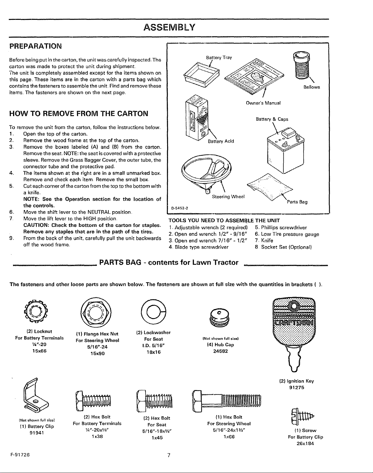
The unit is comptetety assembled except for the items shown on
this page These items are in the carton with a parts bag which
contains the fasteners to assemble the unit Find and remove these
items,, The fasteners are shown on the next page,
HOW TO REMOVE FROM THE CARTON
To remove the unit from the carton, follow the instructions below,.
1. Open the top of the carton,,
2. Remove the wood frame at the top of the carton_
3,, Remove the boxes labeled (A) and (B) from the carton,.
Remove the seat,, NOTE: the seat iscovered with a protective
sleeve. Remove the Grass Bagger Cover, the outer tube, the
connector tube and the protective pad,
4., The items shown at the right are in a small unmarked box.
Remove and check each item Remove the small box°
5. Cut each corner of the carton from the top to the bottom with
a knife,
NOTE: See the Operation section for the location of
the controls,,
6o Move the shift lever to the NEUTRAL position
7, Move the lift lever to the HIGH position
CAUTION: Check the bottom of the carton for staples,,
Remove any staples that are in the path of the tires.
9, From the back of the unit, carefully pull the unit backwards
off the wood frame,
i,,, u ..................., , i ,,,,,,,,,,,,,, i, ,, ,,, ,,,
Bellows
Owner's Manual
TOOLS YOU NEED TO ASSEMBLE THE UNIT
1. Adjustable wrench (2 required) 5 Phillips screwdriver
2. Open end wrench 1/2" - 9/16" 6, Low Tire pressure gauge
3, Open end wrench 7/16" - 1/2" 7o Knife
4. Blade type screwdriver 8 Socket Set (Optional)
___. PARTS BAG - contents for Lawn Tractor ........
The fasteners and other loose parts are shown below,, The fasteners are shown at full size with the quantities in brackets { ),
® @ © @
(2) Locknut (1) Flange Hax Nut (2) Lockwasher
For Battery Terminals For Steering Wheel For Seat [Notshownrut}slzti)
1/_'2B 5/t 6"-24 I.Do 5116" (4) Hub Cap
15×66 15x90 18xl 6 24582
(2) Ignition Key
91275
(Notshawn fullSize)
(1) Battery Clip
91941
12) He× Bolt {2} HBx Bolt (t) Hex Bolt _J_
For Battery Termlnais For Seat For Steering Wheel
V_"-20x%" 5116"_18x_ls" B/16'L24x1 ¥0" (1) Screw
1x38 tx45 lx66 For Battery Clip
26x 184
F-91726 7
ASSEMBLY
HOW TO PREPARE AND
CHARGE THE BATTERY
NOTE; Before you install the battery, add the battery acid
(Electrolyte) and charge the battery° Battery acid will damage
paint and parts,
WARNING: Read the instructions included with
the battery acid container. Protect your hands
ii ii
Remove and discard
the meta_
Vent Cap
_ nd eyes from the battery acid_ Use clothing that
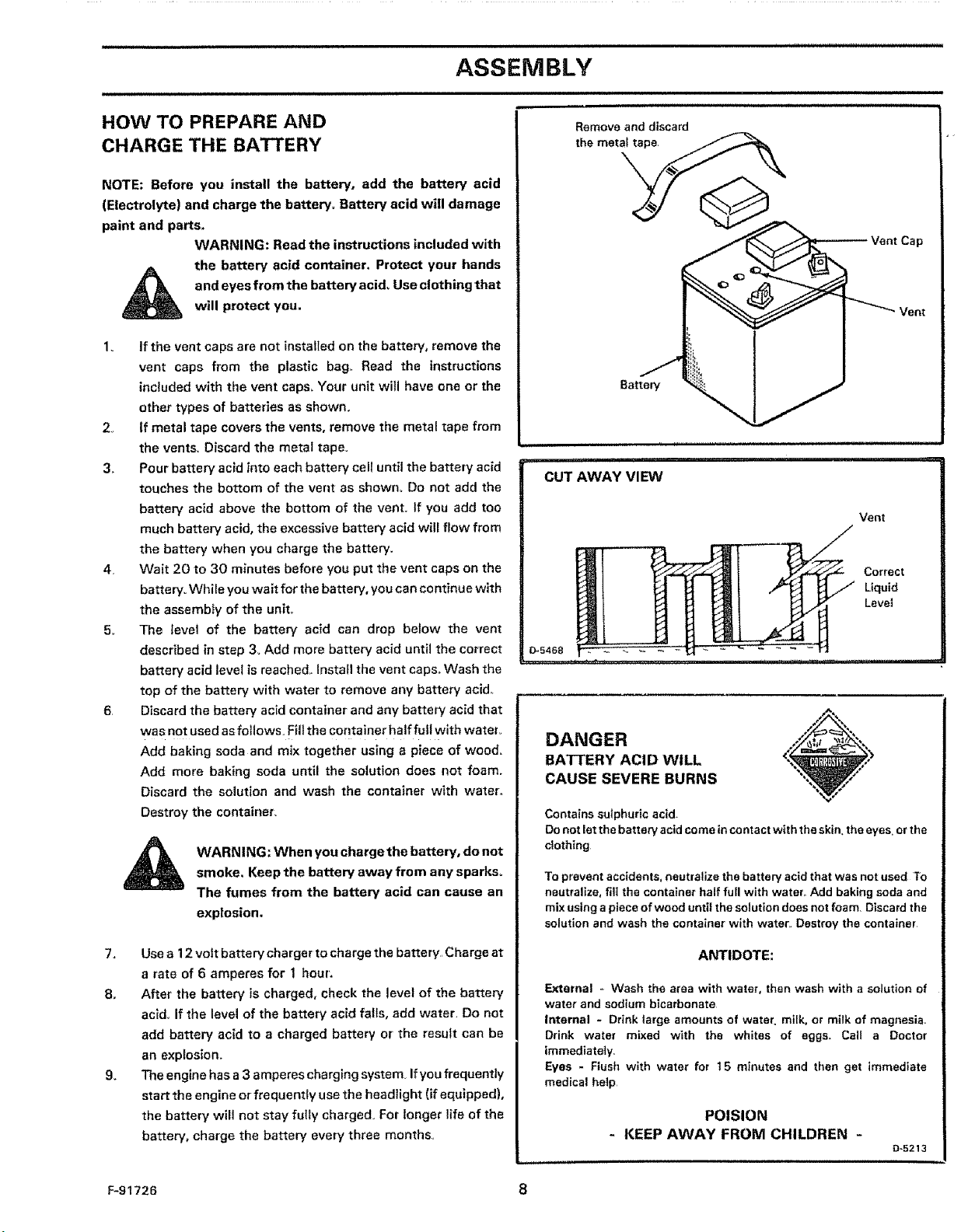
1. If the vent caps are not installed on the battery, remove the
vent caps from the plastic bag Read the instructions
included with the vent caps_ Your unit will have one or the
other types of batteries as shown.
2_ If metal tape covers the vents, remove the metal tape from
the vents. Discard the metal tape.
3. Pour battery acid into each battery cell until the battery acid
touches the bottom of the vent as shown. Do not add the
battery acid above the bottom of the vent. tf you add too
much battery acid, the excessive battery acid will flow from
the battery when you charge the battery.
4. Wait 20 to 30 minutes before you put the vent caps on the
battery° While you wait for the battery, you can continue with
the assembfy of the unit°
5o The level of the battery acid can drop below the vent
described in step 3, Add more battery acid until the correct
battery acid level is reached. Install the vent caps_ Wash the
top of the battery with water to remove any battery acid._
6. Discard the battery acid container and any battery acid that
was not used as follows. Fill the container half full with watery
Add baking soda and mix together using a piece of wood,
Add more baking soda until the solution does not foam.
Discard the solution and wash the container with water..
Destroy the container
will protect you.
Battery
ii ...................
CUT AWAY VIEW
Vent
Correct
Liquid
Level
DANGER
BATTERY ACID WILL
CAUSE SEVERE BURNS
Contains sulphuric acid.
Do not let the battery acid come in contact with the skin,the eyes. orthe
clothing
WARNING; When you chargethe battery, do notsmoke, Keep the battery away from any sparks_
The fumes from the battery acid can cause an
explosion.
7, Use a 12 volt battery charger to charge the battery. Charge at
a rate of 6 amperes for 1 hour,
8o After the battery is charged, check the level of the battery
acid. If the level of the battery acid falls, add water. Do not
add battery acid to a charged battery or the result can be
an explosion.
9. The engine has a 3 amperes charging system If you frequently
start the engine or frequently use the headlight (if equipped),
the battery will not stay fully charged. For longer life of the
battery, charge the battery every three months.
F-91726 8
To prevent accidents, neutralize the battery acid that was not used To
neutralize, fill the container half full with water Add baking soda and
mix using a piece of wood until the solution does not foam, Discard the
solution and wash the container with water Destroy the container
ANTIDOTE:
External = Wash the area with water, then wash with a solution of
water and sodium bicarbonate
Internal = Drink large amounts of water milk, or milk of magnesia
Drink water mixed with the whites of eggs_ Call a Doctor
immediately
Eyes - Flush with water for t5 minutes and then get immediate
medical help
POISION
- KEEP AWAY FROM CHILDREN -
D-5213
ASSEMBLY
_OW TO ASSEMBLE
rilE STEERRNG WHEEL
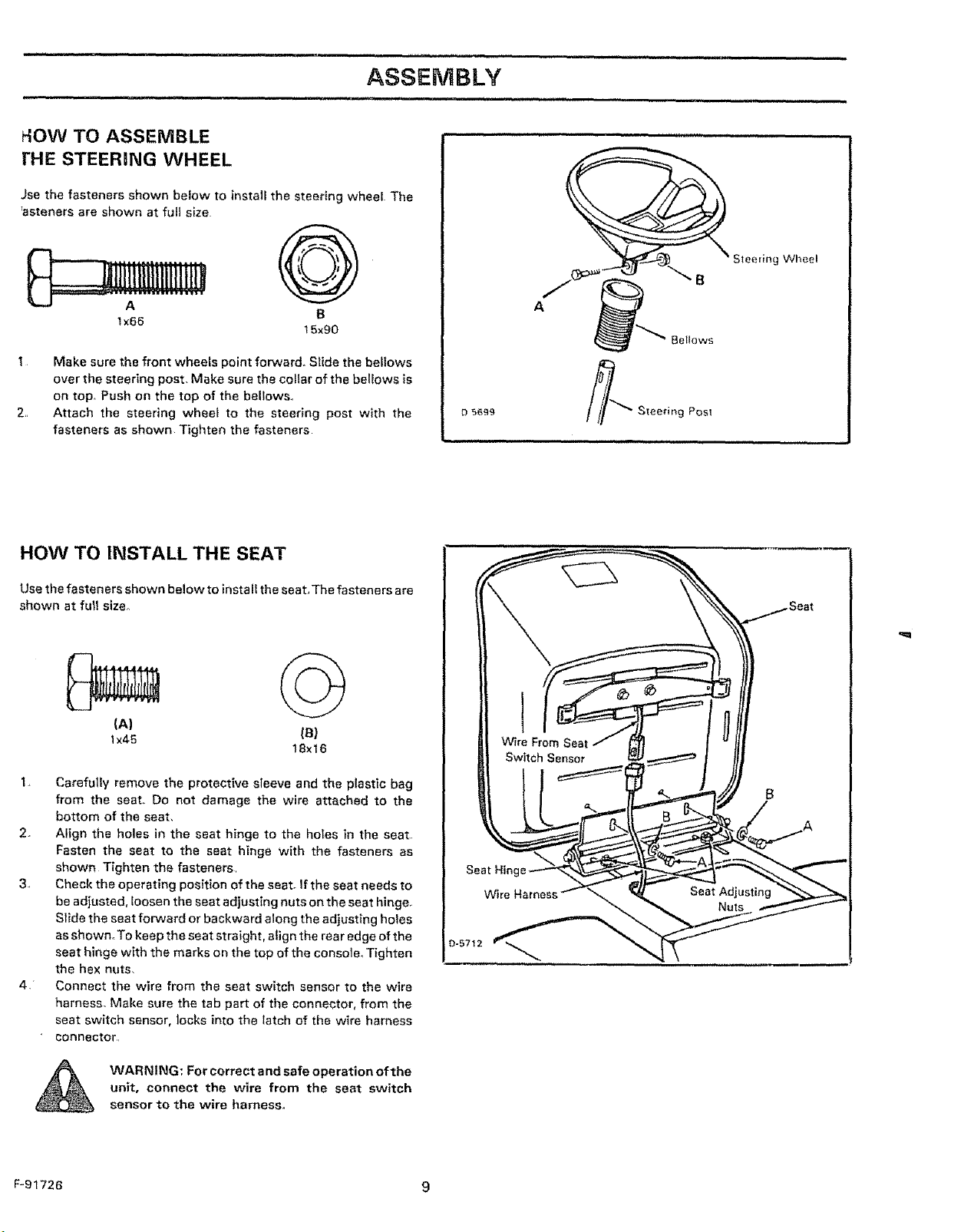
Jse the fasteners shown below to install the steering wheeE The
;asteners are shown at full size
@
S1eedng Wheel
ix66
1 Make sure the front wheels point forward. Slide the bellows
over the steering post. Make sure the collar of the bellows is
on top. Push on the top of the bellows.
2,, Attach the steering wheel to the steering post with the
fasteners as shown Tighten the fasteners
B
t 5×90
HOW TO INSTALL THE SEAT
Use the fasteners shown below to install the seat, The fasteners are
shown at full size°
(A)
Ix45 (8)
18×16
e 5699
B
Bellows
Steering Posl
1. Carefully remove the protective sleeve and the plastic bag
from the seat, Do not damage the wire attached to the
bottom of the seat.
2. Align the holes in the seat hinge to the holes in the seat..
Fasten the seat to the seat hinge with the fasteners as
shown Tighten the fasteners
3, Check the operating position of the seat. If the seat needs to
be adjusted, loosen the seat adjusting nuts on the seat hinge.
Slide the seat forward or backward along the adjusting holes
as shown.To keep the seat straight, align the rear edge of the
seat hinge with the marks on the top of the console_ Tighten
the hex nuts.
4" Connect the wire from the seat switch sensor to the wire
harness. Make sure the tab part of the connector, from the
seat switch sensor, Jocks into the latch of the wire harness
connector,
WARNING: For correct and safe operation ofthe
unit, connect the wire from the seat switch
sensor to the wire harness.
F-91726 9
Seat
= == =l= H =l=l,====,l,l,l,l,l==l,l=ll=l===
ASSEMBLY
= 111i= iH ,lliHi,i,ll
HOW TO ATTACH THE HUB CAPS
Push each hub cap onto the center' hub of each wheel, Make sure
the washer holds the hub cap in place_
CHECK THE TIRES
Check the air pressure in the tireSr.Tireswith too much airpressure
will cause the unit to ride rough. Also, the wrong air pressure will
keep the mower housing from cutting level, The correct air
pressure (PSI) is 12 PSI (0,B5 kg/cm2),
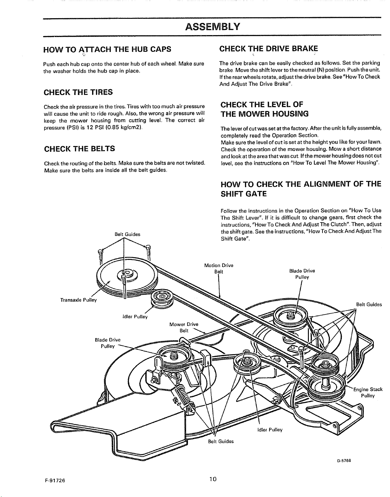
CHECK THE BELTS
Check the routing of the belts. Make sure the belts are not twisted.
Make sure the belts are inside all the belt guides_
Belt Guides
CHECK THE DRIVE BRAKE
The drive brake can be easily checked as foHows_ Set the parking
brake Move the shift lever to the neutral (N) position Push the unit.
If the rear wheels rotate, adjust the drive brake. Seo "How To Chock
And Adjust The Drive Brako'_
CHECK THE LEVEL OF
THE MOWER HOUSING
The lever of cut was set at the factory,, After the unit is fully assemble,
completely read the Operation Section.
Make sure the level of cut is set at the height you like for your lawn,.
Check the operation of the mower housing° Mow a short distance
and look at the area that was cut. If the mower housing does not cut
level, see the instructions on "How To Level The Mower Housing"_
HOW TO CHECK THE ALIGNMENT OF THE
SHIFT GATE
Follow the instructions in the Operation Section on "How To Use
The Shift Lever"., If it is difficult to change gears, first check the
_nstructions, "How To Check And Adjust The Clutch". Then, adjust
the shift gate.. See the irrstructions, "How To Check And Adjust The
Shift Gate",
Transaxle Pulley
Blade Drive
Pulley
Belt Guides
idler Pulley
Mower Drive
Belt
Stack
Pulley
Idler Put{ey
Belt Guides
F-91726 t 0
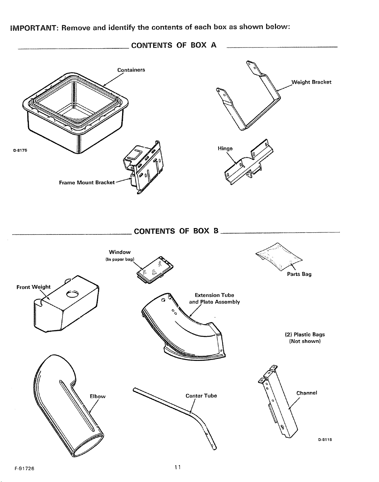
iMPORTANT: Remove and identify the contents of each box as shown below:
CONTENTS OF BOX A
Containers
Hin_
Frame Mount Bracket _L=_
Weight Bracket
Fr°ntWi_"
Elbow
Window
(In paper bag_
CONTENTS OF BOX B
Parts Bag
Extension Tube
and Plate Assembly
(2) Plastic Bags
(Not shown)
\
Channel
F_91726 I 1
D-81_8
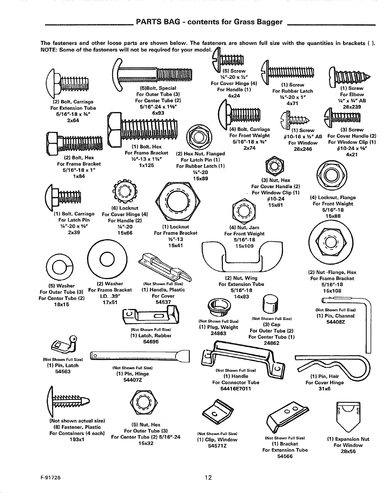
PARTS BAG - conterlts for Grass Bagger
The fasteners and other loose parts are shown below. The fasteners are shown full size with the quantities in brackets ().
NOTE: Some of the fasteners will not be required for your modoLi_., ..,..
_,_"-20 x ½"
3 For Cover Hinge (4)(5)Bolt,Special
For Outer Tuba (3)
(2) Bolt, Carriage For Center Tube (2)
For Extension Tube 5/16"-24 x 1% _
5/16"-18 x ¾" 6x93
2x64
(1) Bolt, Hex
(2) Bolt, Hax
For Frame Bracket
5/t6"-1B x 1_
I x84
(1) Bolt, Carriage For cover Hinge [4)
For Latch Pin For Handle (2)
1/4"-20 x s/a" ¼"-20
2x39 15x66
For Frame Bracket
½"-13 x t¼_
lx125
(6) LocknQ
(t) Locknut
For Frame Bracket
For Handle (1)
@
(2) Hex Nut, Flanged
For Latch Pin (1)
For Rubber Latch (1)
¼"-20
15x89
L4x24
(4) Bolt, Carriage
For Front Weight
5/16_-18 x ¾_
2x74
(3) Nut, Hax
For Cover Handle (2)
For Window Clip (1)
Q #10-24
(4) Nut, Jam
For Front Weight
5/16"-t8
(1) Screw
For Rubber Latch
1/_-20 x 1_ For Elbow
4x71
(1_) Screw 131Screw
#10-t6 x ½" AB For Cover Handle (2)
For Window For Window Ctip (1)
26x246 #10-24 X %"
@
(4) Locknut, Flange
15x81
For Front Weight
5/16"-18
15x88
¼" x ¾" AB
26x239
4x21
_;_143
151Washer 121Washer (NotShownFullSize)
For Outer Tube (3) For Frame Bracket (I) Handle, Plastic
For Center Tube (2) LD. °39" For Cover
18xl 5 17x51 54537
{Not Shown Full Size}
54695
(1) Latch, Rubber
{Not Shown Futl Size|
(1) Pin, Latch
54563
(Not shown actual size)
(8} Fastener, Plastic
For Containers (4 each)
193xl
(NotShowni_[t Size)
(1) Pin, Hinge
54407Z
151Nut, Hex
For Outer Tube (3) {NotShownFullSizel
For Center Tube (2) 5/16"-24 (1) Clip, Window (NotShownFullSize}
16X32 54571Z (1) Bracket
;; 15x109
(2) Nut, Wing
For Extension Tube
5/16'_18
@ 14x83 _
(Not ShownFullSize) (NotShownFullSize)
(1) Plug, Weight (3) Cap
24863 For Outer Tube (2)
For Center Tube (1)
2
For Connector Tube
54416E7011
For Extension Tube
54566
121Nut -Flange, Hex
For Frame Bracket
5116"-18
15xl 08
ForCover Hinge
31x6
(1) Expansion Nut
For Window
28x56
F-91726 12
ASSEMBLY
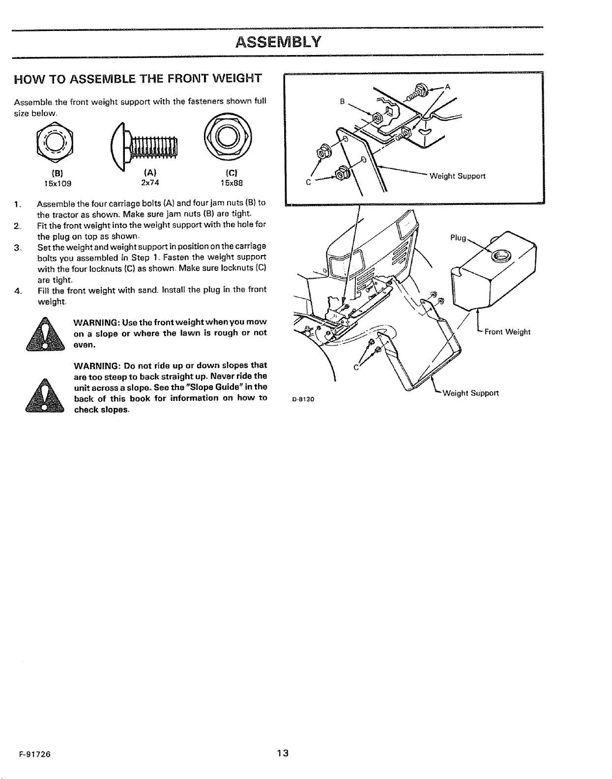
HOW TO ASSEMBLE THE FRONT WEIGHT
Assemble the front weight support with the fasteners shown full
size below,
©
(B)
15x 109
1, Assemble the four carriage bolts (A) and four jam nuts (B) to
the tractor as shown,, Make sure jam nuts (B) are tight°
2, Fit the front weight into the weight support with the hole for
the plug on top as shown,
3o Set the weight and weight support in position on the carriage
bolts you assembled in Step 1- Fasten the weight support
with the four Iocknuts (C} as shown, Make sure Iocknuts (C}
are tight,
4_ Fill the front weight with sand,, Install the plug in the front
weight.
on a slope or where the lawn is rough or not
WARNING: Use the front weight when you mow
even.
WARNING: Do not ride up or down slopes that
are too steep to back straight up. Never ride the
unit across a slope. See the "Slope Guide" in the
back of this book for information on how to
check slopes_
(A) (c)
2x74 15x88
C_ .3_ Weight Support
O-e130
Weight Support
F-91726 13
iii iiiiiii1,,111
ASSEMBLY
H =l= =H,N ::::::::::::::::::::::::::::::::
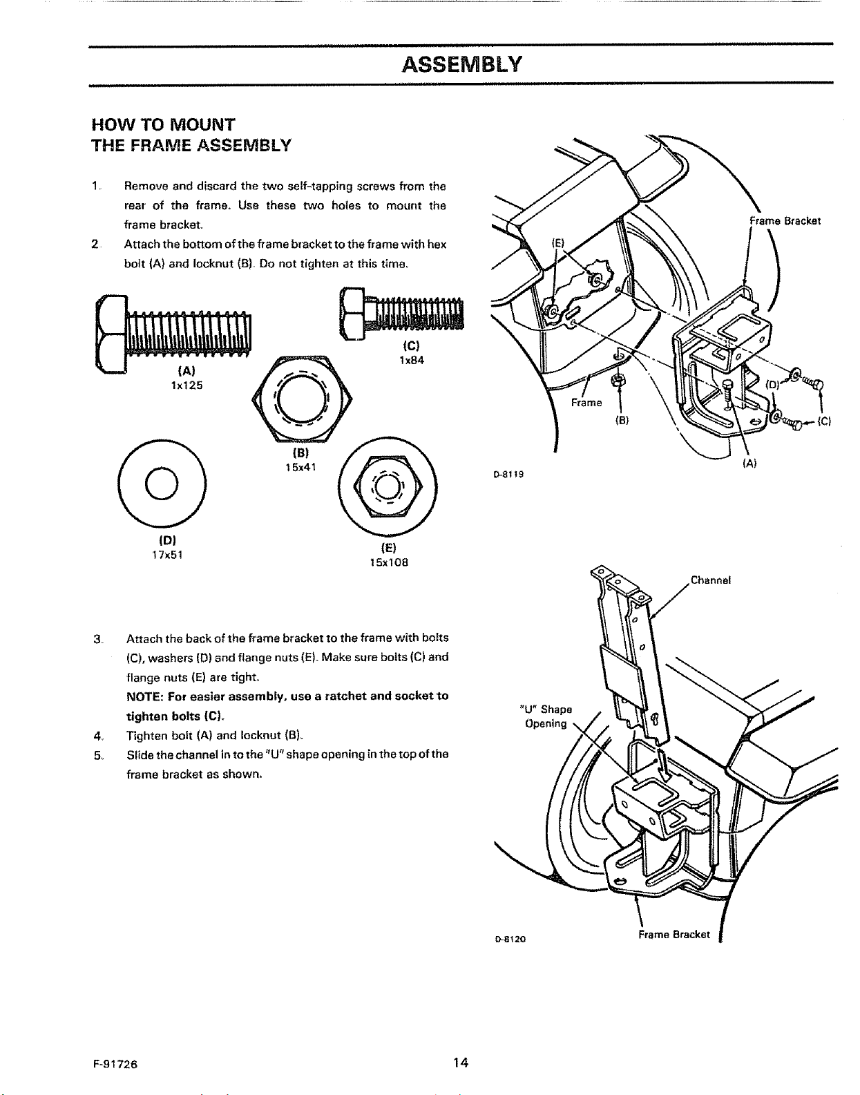
HOW TO MOUNT
THE FRAME ASSEMBLY
Remove and discard the two self=tapping screws from the
rear of the framer Use these two holes to mount the
frame bracket_ FrameBracket
Attach the bottom of the frame bracket to the frame with hex
2.
bolt (A} and Iocknut (B) Do not tighten at this t_me=
(A)
lx125
,
15x41 __
(D)
17x51
3_ Attach the back of the frame bracket to the frame with bolts
(C), washers (D) and flange nuts (E)._Make sure botts (C) and
flange nuts (E) are tight.
NOTE: For easier assembly, use a ratchet and socket to
tighten bolts (C).
4_ Tighten bolt (A) and Iocknut (B}.
5.. Slide the channel in to the "U" shape opening in the top oftha
frame bracket as shown,
(E)
15x108
0-8t19
(A)
Channel
"U" Shape
Opening \
F-91726 14
D-8_20
Frame Bracket
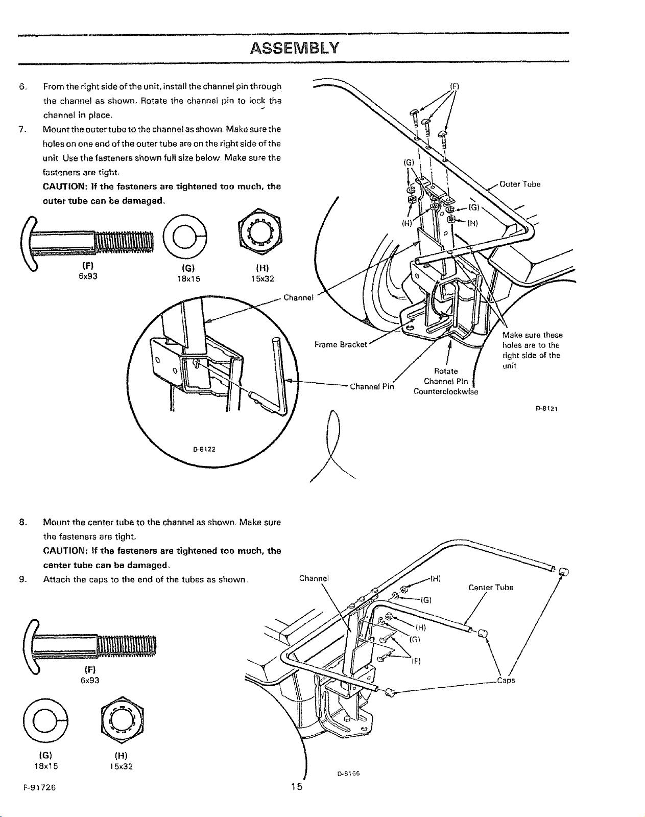
6,
From the right side of the unit, install the channel pin throug h
the channel as shown, Rotate the channel pin to lock the
channe_ in place,
7_
Mount the outer tube to the channel as shown, Make sure the
holes on one end of the outer tube are on the right side of the
unit, Use the fasteners shown full size below Make sure the
fasteners are tight_
CAUTION: If the fasteners are tightened too much, the
outer tube can be damaged.
(F)
(G)
©
IF) (G)
6xg3 t8x 15
8 Mount the center tube to the channel as shown Make sure
the fasteners are tight,
CAU'flON: If the fasteners are tightened too much, the
center tube can be damaged,
9. Attach the caps to the end of the tubes as shown
@
(H)
15x32
Channel
Channel Pin
Rotate
Channel Pin
Counterclockwise
Make sure these
holes are to the
right side of the
unit
e-8!21
Center Tube
(F}
6x93
G Q
(G) (H)
! 8x 15 15x32
F-91726 15
(F)
IIIHII=I=IIIll i=i
ASSEMBLY
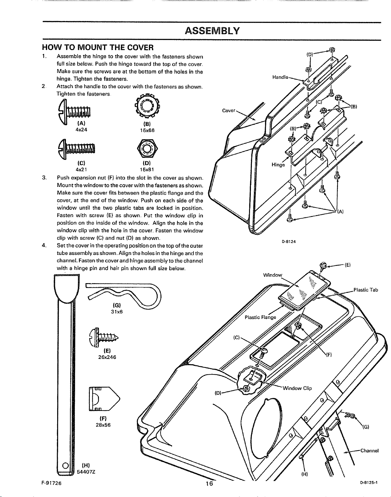
HOW TO MOUNT THE COVER
1o Assemble the hinge to the cover with the fasteners shown
full size below,. Push tire hinge toward the top of the cover,,
Make sure the screws are at the bottom of the holes in the
hinge,, Tighten the fasteners.
2 Attach the handle to the cover with the fasteners as shown.
Tighten the fasteners,
_(A) (a)
4x24 15x66
(c) (D)
4x21 15x81
3_
Push expansion nut (F) into the slot in the cover as shown,,
Mount the window to the cover with the fasteners as shown°
Make sure the cover fits between the plastic flange and the
cover, at the end of the window° Push on each side of the
window until the two plastic tabs are locked in position°
Fasten with screw (E) as shown, Put the window clip in
position on the inside of the window,. Align the hole in the
window clip with the hole in the cover° Fasten the window
clip with screw (C) and nut (D) as shown,
4.
Set the cover in the operating position on the top of the outer
tube assembly as shown. Align the holes in the hinge and the
channel. Fasten the cover and hinge assembly to the channel
with hinge pin and hair pin shown full size below.
D-S124
W_ndow
F-9t726
O
),
(H)
54407Z
Plastic Tab
31x6
Pfastic Flange
(El
26_.46
IF)
28x56
(H)
!6
................................ i,, ,lui un,lllli,l_Jii
ASSEMBLY
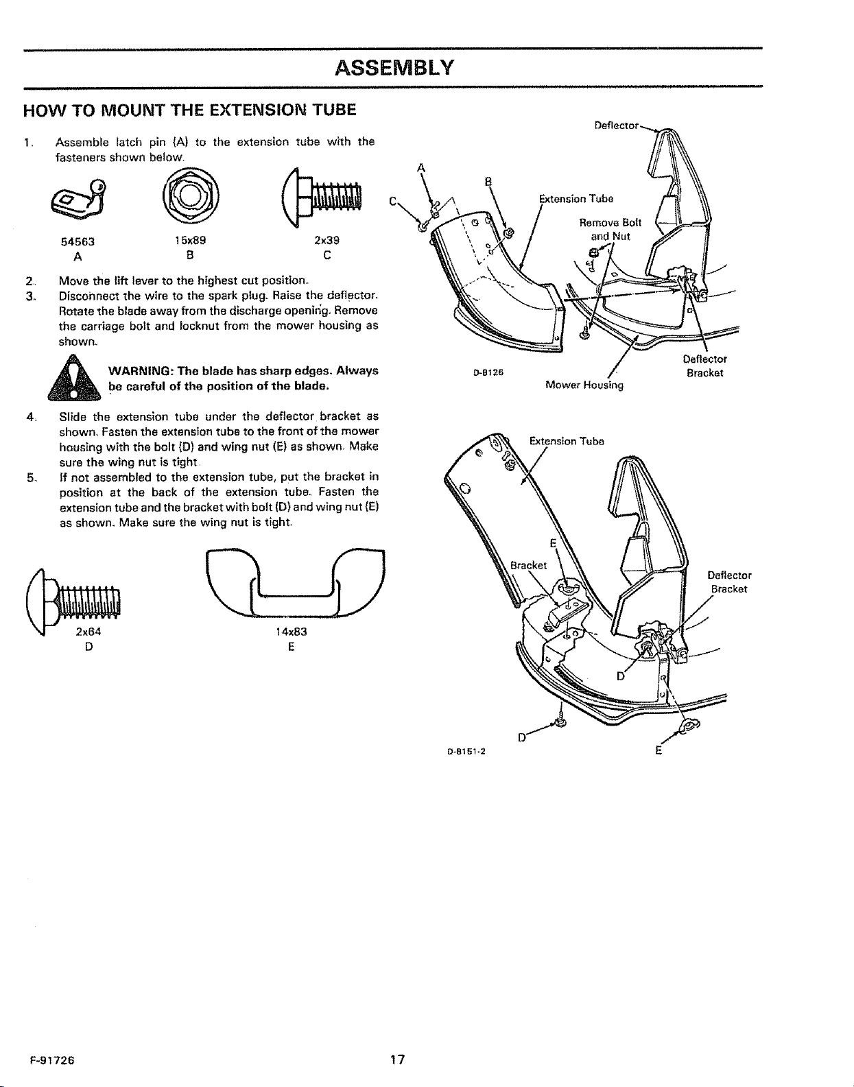
HOW TO MOUNT THE EXTENSION TUBE
1,, Assembfe latch pin (A) to the extension tube with the
fasteners shown below
54563 15x89 2x39
A B C
2, Move the lift lever to the highest cut position,
3. Disconnect the wire to the spark plug. Raise the deflector,
Rotate the blade away from the discharge openir;g, Remove
the carriage bolt and Iocknut from the mower housing as
shown.,
_ ARNING: The blade has sharp edges_ Always
4, Slide the extension tube under the deflector bracket as
shown_ Fasten the extension tube to the front of the mower
housing with the bolt (D) and wing nut (E) as shown. Make
sure the wing nut is tight,
5- ff not assembled to the extension tube, put the bracket in
position at the back of the extension tube_ Fasten the
extension tube and the bracket with bolt (D) and wing nut (E)
as shown. Make sure the wing nut is tlght,,
be careful of the position of the blade.
A
Deflector
D-B126
Mower Housing
Extension Tube
Bracket
2x64
D
Deflector
Bracket
14x83
E
a-8151-2
F-91726 17
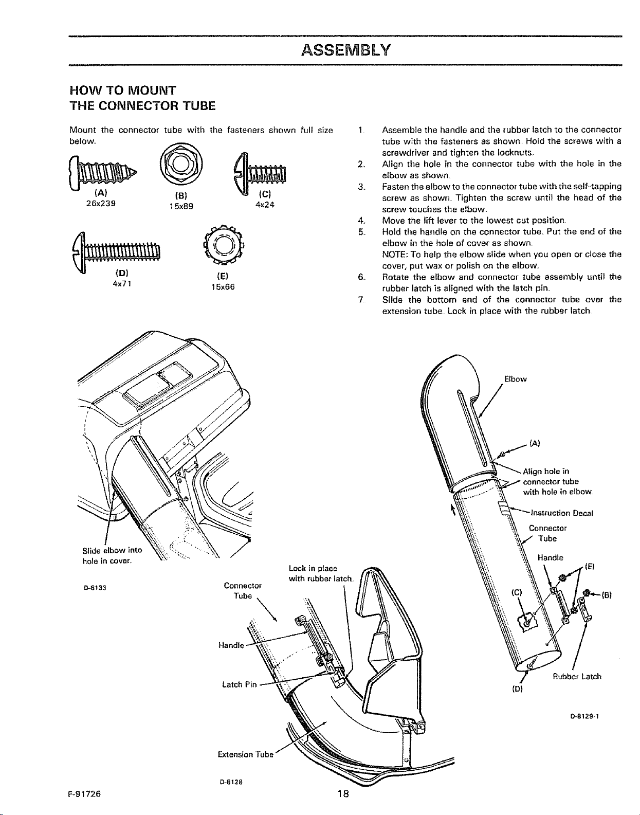
HOW TO MOUNT
THE CONNECTOR TUBE
ASSEMBLY
Mount the connector tube with the fasteners shown full size
below,,
(B)
26x239 15x89 4x24
(E)
4x71 15x66
1 Assemble the handle and the rubber latch to the connector'
tube with the fasteners as shown,_ Hoid the screws with a
screwdriver and tighten the Iocknuts,
2, Atign the hole in the connector tube with the hole in the
elbow as shown_
3, Fasten the elbow to the connector tube with the self=tapping
screw as shown Tighten the screw until the head of the
screw touches the elbow,
4, Move the lift lever to the lowest cut position_
5_ Hold tire handle on the connector tube,, Put the end of the
elbow in the hole of cover as shown,,
NOTE: To help the elbow slide when you open or close the
cover, put wax or polish on the elbow,
6. Rotate the efbow and connector tube assembly until the
rubber latch is aligned whh the latch pin
7 Slide the bottom end of the connector tube over the
extension tube Lock in place with the rubber latch,
Elbow
Slide elbow into
hole in cover_
D-8133
CoRRecter
Tube_
Handle,
hole in
with hole in elbow
Conoector
Tube
Lock in piece
whh rubber latch
Rubber Latch
(D)
D-S129-f
F-91726 18
ASSEMBLY
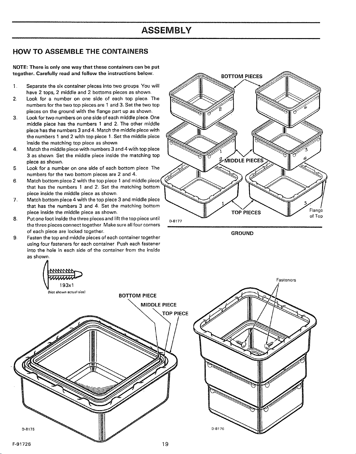
HOW TO ASSEMBLE THE CONTAINERS
NOTE: There is only one way that these containers can be put
together. Carefully read and follow the instructions below_,
1 Separate the six container pieces into two groups You will
have 2 tops, 2 middle and 2 bottoms pieces as shown,
2, Look for a number on one side of each top piece The
numbers for the two top pieces are I arid 3. Set the two top
pieces on the ground with the flange part up as shown,
3. Look for two numbers on one side of each middle piece_ One
middle piece has the numbers 1 and 2, The other middle
piece has the numbers 3 and 4. Match the middle piece with
the numbers 1 and 2 with top piece 1. Set the middle piece
inside the matching top piece as shown
4. Match the middle piece with numbers 3 and 4 with top piece
3 as shown Set the middle piece inside the matching top
piece as shown,,
5, Look for a number on one side of each bottom piece The
numbers for the two bottom pieces are 2 and 4o
6, Match bottom piece 2 with the top piece 1 and middle piece1
that has the numbers 1 and 2. Set the matching bottom
piece inside the middle piece as shown
7 Match bottom piece 4 with the top piece 3 and middle piece
that has the numbers 3 and 4, Set the matching bottom
piece inside the middle piece as shown_
8, Put one foot inside the three pieces and lift the top piece until
the three pieces connect together Make sure all four corners
of each piece are locked together.,
9, Fasten the top and middle pieces of each container together
using four fasteners for each container Push each fastener
into the hole in each side of the container from the inside
as shown,
D_8177
BOTTOM PIECES
TOP PIECES Flange
GROUND
of Top
i i
(No_ shown _ctua! s_ze}
BOTTOM PIECE
MIDDLE PIECE
TOP PIECE
F-91726 19
Fasteners
ASSEMBLY
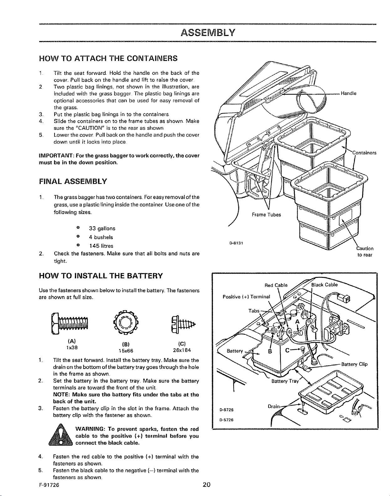
HOW TO ATTACH THE CONTAINERS
1 Tilt the seat forward Hold the handle on the back of the
cover,, Pull back on the handle and lift to raise the cover
2 Two plastic bag linings, not shown in the illustration, are
included with the grass bagger The plastic bag linings are
optiona] accessories that can be used for easy removal of
3,. Put the plastic bag linings in to the containers
4, Slide the containers on to the frame tubes as shown Make
sure the "CAUTION" is to the rear' as si_own
5, Lower the cover Pull back on the handle and push the cover
the grass,, I
down unti_ it locks into place
IMPORTANT: For the grass bagger to work correctly, the cover
must be in the down position,.
FINAL ASSEMBLY
1, The grass bagger has two containers. For easy removal of the
grass, use a plastic lining inside the container Use one ofthe
following sizes°
i lllll illll i
e 33 gallons
e 4 bushels
e 145 litres
2+
Check the fasteners° Make sure that alt bolts and nuts are
tight,,
HOW TO INSTALL THE BATTERY
Use the fasteners shown below to install the battery, The fasteners
are shown at full size,
(A) (B) (C)
lx38
1o Tilt the seat forward Install the battery tray_ Make sure the
drain on the bottom ofthe battery tray goes through the hote
in the frame as shown,
2,, Set the battery in the battery tray, Make sure the battery
terminals are toward the front of the unit,
NOTE: Make sure the battery fits under the tabs at the
back of the unit.
3° Fasten the battery clip in the slot in the frame,, Attach the
battery clip with the fastener as shown,
t 5x66 26x184
0-8131
;_ Caution
to rear
_ WARNING: To prevent sparks, fasten the red
4. Fasten the red cable to the positive (+) terminal with the
fasteners as shown_
5, Fasten the black cable to the negative (--) terminal with the
fasteners as shown,
F-91726 2O
cable to the positive (+) terminal before you
connect the black cable,
i , ,
OPERATION
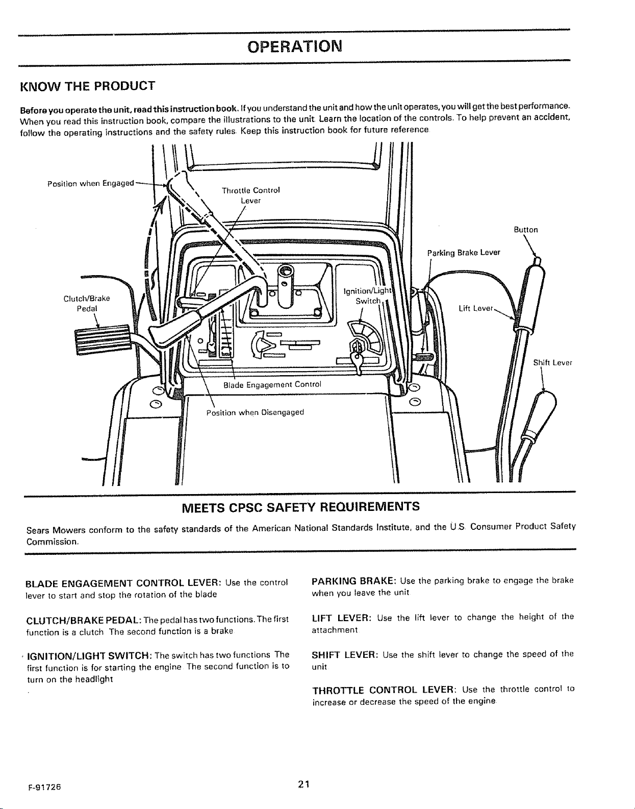
KNOW THE PRODUCT
Before you operate the unit, read this instruction book° If you understand the unit and how the unit operates, you will get the best performance.
When you read this instruction book, compare the illustrations to the unit. Learn the location of the controls. To help prevent an accident,
follow the operating instructions and the safety rules Keep this instruction book for future reference
Position w _en Enga(
Button
!
Clutch/Brake lgnitloniLight
Pedaf Switch,
Blade Engagement Control
Parking Brake Lever
O Q
Position when Disengaged
ill ill,ii u i i ii ii ii i ,llllll,lll,ii ii ii ii ,i,,ll i ,, illUll,,i ,,i i
MEETS CPSC SAFETY REQUIREMENTS
Sears Mowers conform to the safety standards of the American National Standards Institute, and the US Consumer Product Safety
Commission,,
i illlUHlll i Hu, .ll UUlmlIHH 'llHJl I I III,H
BLADE ENGAGEMENT CONTROL LEVER: Use the control
lever to start and stop the rotation of the blade
CLUTCH/BRAKE PEDAL: The pedal has two functions The first
function is a clutch The second function is a brake
IGNIT|ON/LIGHT SWITCH: The switch has two funct}ons The
first function is for starting the engine The second function is to
turn on the headlight
F191726 2t
PARKING BRAKE: Use the parking brake to engage the brake
when you leave the unit
LIFT LEVER: Use the lift lever to change the height of the
attachment
SHIFT LEVER: Use the sh_ft lever to change the speed of the
unit
THROTTLE CONTROL LEVER: Use the throttle control to
increase or decrease the speed of the engine
 Loading...