

Craftsman 502255070 Owner’s Manual

Moden o=
502=255070
C START
CAUTnON:
Read And Follow
I 0 HPoELECT
30" OW
5 $P
All Safety Rules
And instructions
Before Operating
This Equipment.
ulu_
F-93602 Sears, Roebuck and Co., Hoffman Estates, IL. 60179 U.S.A. PrintedinUSA.
EAR E G
Assembly
Operation
Customer Responslbiaities
Service And Adjustment

TABLE OF
CONTENTS
WARRANTY ........................................ 2
CUSTOMER RESPONSIBILITIES .................... 3
PRODUCT SPECIFICATIONS ......................... 3
SAFETY RULES ................................... 4
ACCESSORIES AND ATTACHMENTS .................. 6
ASSEMBLY ....................................... 7
HOW TO PREPARE AND CHARGE THE BATTERY ....... 8
HOW TO ASSEMBLE THE STEERING WHEEL ........... 9
HOW TO ASSEMBLE THE HUB CAPS .................. 9
CHECKTHE TIRES .................................... 9
CHECK THE DRIVE BRAKE ............................. 9
CHECK THE BELTS ........................... ;....... 9
HOW TO INSTALL THE BATTERY ...................... 10
HOW "TOINSTALL THE SEM' . ......................... 11
CHECK 1HE LEVEL OF THE MOWER HOUSING ......... 11
HOW TO MOUNlr THE FRAME ASSEMBLY ............... 14
HOW TO MOUNT THE COVER ......................... 15
HOW TO MOUNT THE EXTENSION TUBE ............... 16
HOW TO MOUNT THE CONNECTOR TUBE .............. 17
HOW TO ASSEMBLE THE CONTAINERS ................ 18
HOW TO MOUNT THE CONTAINERS ................... 19
HOW TO tNSTALL THE FRONT WEIGHT ................ 19
HOW TO INSTALL THE MULCHER PLATE ............... 20
OPERATION ....................................... 21
LOCATION OF CONTROLS ............................ 21
HOW TO USE THE THROTTLE CONTROL ............... 22
HOW TO USE THE ATTACHMENT CLUTCH ............. 22
HOW TO USE THE SHIFT LEVER ....................... 22
HOW TO SET THE PARKINGBRAKE ................... 23
HOW TO CHANGE 'THECUTTING HEIGHT .............. 23
HOW TO STOP "THEUNIT'. ............................. 23
HOW TO TRANSPORT THE UNIT ....................... 23
HOW TO OPERATE WITH THE MOWER HOUSING ....... 24
HOW TO OPERATE THE UNITON HILLS ................ 24
HOW TO USE THE GRASS BAGGER ................... 25
BEFORE STARTING THE ENGINE ...................... 26
HOW TO START THE ENGINE .......................... 26
HOW TO START WITH A WEAK BATTERY .............. 26
OPERATING TIPS ..................................... 27
MOWING AND BAGGING TIPS ........................... 27
MULCHING TIPS ........................................ 27
CUSTOMER RESPONSIBILITIES .................... 28
MAIN'rENANCE CHART ............................... 28
CHECK THE TIRES .................................... 28
HOW TO REMOVE AND INSTALL THE BLADE ........... 29
HOW TO SHARPEN THE BLADE ........................... 29
HOW TO ADJUST THE ATTACHMENT CLUTCH .......... 30
HOW TO CHECK AND ADJUST THE DRIVE BRAKE ...... 31
HOW TO CHECK AND ADJUST THE CLUTCH ............ 31
HOW TO REMOVE THE SIDE PANEL ................... 32
BATTERY SERVICE ......................................... 32
HOW TO CHECK AND CHARGE THE BATTERY ......... 32
WHERE TO LUBRICATE ............................... 33
HOW TO CHECK THE OIL ............................. 34
HOW 1'O CHANGE THE OIL ............................ 34
HOW TO CLEAN THE COOLING SYSTEM ............... 34
HOW TO CHECK THE MUFFLER ........................ 34
HOW TO CLEAN THE AIR RLTERS ..................... 35
HOW "fO CHECK THE SPARK PLUG .................... 35
SERVICE AND ADJUSTMENT ....................... 36
HOW TO ADJUST THE CARBURETOR .................. 36
HOW TO ADJUST THE THROTTLE CONTROL ............ 36
HOW TO REMOVE THE MOWER HOUSING ............. 37
HOW TO INSTALL THE MOWER HOUSING .............. 37
HOW _O LEVEL THE MOWER HOUSING ................ 38
HOW TO REPLACE THE MOTION DRIVE BELT .......... 39
HOW TO REPLACE THE MOWER DRIVE BELT .......... 40
HOW TO REPLACE THE FUSE ......................... 41
HOW TO SET' THE CUTTING HEIGHT ................... 41
HOW TO CLEAN THE MOWER HOUSING ............... 41
FRONT WHEEL ALIGNMENT ........................... 41
HOWTO CLEAN THE GRASS BAGGER .................. 41
STORAGE (OVER 30 DAYS) .............................. 42
TROUBLE SHOOTING CHART ...................... 43
SLOPE GUIDE ........................................ 44
INDEX ............................................ 47
LIMITED TWO YEAR WARRANTY
ON ELECTRIC START RIDING EQUIPMENT
AND GRASS CATCHER ATTACHMENT
For two (2) years from the date of purchase, ifthis riding equipment and grass catcher attachment is maintained, lubricated
and tuned up according to the instructions in the owner's manual, Sears wilt repair or replace, free ofcharge, any parts found
to be defechve in material or workmanship.
This warranty does not cover:
o Expendable items which becon'le worn during normal use, such as blades, spark plugs, air cleaners and belts.
o Tire replacement or repair caused by punctures from outside objects, such as nails, thorns, stumps or glass.
'_ Repairs necessary because of operator abuse, negligence, improper storage or accident or the failure to maintain the
equipment according to the instructions contained in the owner's manual
• Riding equipment used for commercial or rental purposes.
LIMITED 90 DAY WARRANTY ON BATTERY
For 90 days from the date of purchase, if any battery includedwiththis ridingequipment proves defectivein material or
workmanship and our testing determines the battery will not h01da charge, Sears will replacethe battery at no charge_
WARRANTY SERVICEIS AVAILABLEBY RETURNING THE RIDING EQUIPMENTTO THE NEAREST SEARS SERVICE
CENTER/DEPARTMENT IN THE UNITED STATES.
This warrantygives you specific legalrights,and you may also haveotherrights whichmay vary from stateto state
Sears, Roebuck and Co. Hoffman Estates 60179
t:-93602 2

Congratulations on your purchase of a Sears Rider, It has been
designed, engineered and manufactured to give you the best
possible dependability and performance°
If you experience any problems you cannot easily remedy, please
see your nearest Sears Service Department, We have competent,
well trained technicians and the proper tools to service or repair this
unit.
Please read and keep this manual. The instructions will enable you
to assemble and maintain your unit properly° Always observe the
"Safety Rules",
CUSTOMER RESPONSIBILITIES
e Carefully read and follow the rulesfor safe operation° Inspect
the unit.
e Follow all the assembly instructions° Carefully adjust the uniL
e Know howto operate all standard and accessary equipment on
the unit..Make sure the operator can correctly operate the uniL
e Operate the unit only with guards, shields and other safety
items in place and working correctly,
e Complete all maintenance on the unit,,Service the unit only with
authorized or approved replacement parts.,
® See the Maintenance Chart.,
NOTE: This unit isequipped with an internal combustion engine and
must not be used on or near any unimproved forest-covered,
brush--covered or grass-covered land unless the engine's exhaust
system is equipped with a spark arrester meeting applicable local
or state laws (if any),, If a spark arrester is used, it must be
maintained in effective working order by the operator_
Inthe State of California, the above is required by law (Section 4442
of the California Public Resources Code). Other states may have
similar laws, Federal laws apply on federal lands. See an Authorized
Service Center for a spark arrester for the muffler°
MAINTENANCE AGREEMENT
A Sears Maintenance Agreement is available on this unit See the
nearest Sears Store for information,
PRODUCT SPECIFICATIONS
Craftsman Engine ........ 10 HP,
Charging System ......... 3 amperes at 3600 rpm
Fuel Tank Size ........... 3 quarts
Type of Fuel .............. Unleaded Regular
Oil Capacity .................. 2 pints
Oil Type ................. Above 32 degrees SAE 30
.................................... Below 32 degrees SAE 5W30
Spark Plug (Gap 0,,030") .. Champion J-8C
.......................... Sears 71-33312
.......................... STD361458
Tire Air Pressure ......... Front 24 psi (See tire sidewall)
Tire Air Pressure ......... Rear t4 psi (See tire sidewaIf)
All Gear Transaxte ........ 5 forward speeds and 1 reverse
Ground Speed Range ...... Forward 0-4,3 mph
.................................. Reverse 0-2.1 mph
Tilt Seat ................. Tilts forward to access the battery_
Mower Housing ........... Full-floatingsuspension,oneblade,
Cutting Height ................. 8 positions from 1_/2to 4 inches_
Blade Nut Torque ......... 30 foot-pounds (ft-lbs)
Grass Bagger Capacity ooo 7 Bushels
Rear Engine Rider
Record in the space below the serial number and the date
of purchase of this unit
The model number and serial number are found on a decal
attached to the rear of the frame_
Model Number: 5;02,255070
Serial Number:
Date of Purchase:
Keep these numbers for future reference.
F-93602 3
SAFETY RULES
Safe Operation Practicesfor Riding Vehicles
As Recommended by American National Standards Institute
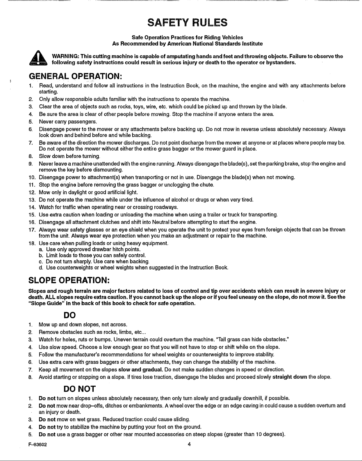
WARNING: This cutting machine is capable of amputating hands andfeet andthrowing objects. Failure to observethe
following safety instructions could result in serious injury or death to the operator or bystanders.
GENERAL OPERATION:
t. Read, understand and follow all instructions in the Instruction Book, on the machine, the engine and with any attachments before
starting.
2o Only allow responsible adults familiar Withthe instructions to operate the machine_
3. Clear the area of objects such as rocks, toys, wire, etc. which could be picked up and thrown by the blade.
4. Be sure the area is clear of other people before mowing.. Stop the machine if anyone enters the area.
5_ Never carry passengers,.
6. Disengage power to the mower or any attachments before backing up. Do not mow in reverse unless absolutely necessary. Always
look down and behind before and while backing.
7. Be aware of the direction the mower discharges. Do not point discharge from the mower at anyone or at places where people may be.
Do not operate the mower without either the entire grass bagger or the mower guard in place.
8. SIowdownbeforeturningv
9. Never leave a machine unattended with the engine running. Always disengage the blade(s), set the parking brake, stop the engine and
remove the key before dismounting_
!0o Disengage power to attachment(s) when transporting or not in use. Disengage the blade(s) when not mowing.
!1. Stop the engine before removing the grass bagger or unclogging the chute.
12, Mow only in daylight or good artificial light.
13. Do not operate the machine while under the influence of alcohoI or drugs or when very tired,
14. Watch for traffic when operating near or crossing roadways.
15. Use extra caution when loading or unloading the machine when using a trailer or truck for transporting,
16. Disengage all attachment clutches and shift into Neutral before attempting to start the engine.
17. Always wear safety glasses or an eye shield when you operate the unit to protect your eyes from foreign objects that can be thrown
from the unit° Always wear eye protection when you make an adjustment or repair to the machine.
18. Use care when pulling loads or using heavy equipmenL
a. Use only approved drawbar hitchpoints.
b. Limit loads to those you can safely control.
c. Do not turn sharply. Use care when backing,
d. Use counterweights or wheel weights when suggested inthe Instruction Book.
SLOPE OPERATION:
Slopesand roughterrain are major factors related to loss of control and tip over accidents which can result in severe injuryor
death. ALL slopes requireextra caution. Ifyou cannotback up the slopeor ifyou feel uneasy on the slope, do not mowit. Seethe
"Slope Guide" inthe back of this book to check for safe operation.
DO
1, Mow up and down slopes, not across.
2. Remove obstacles such as rocks, limbs, etc._
3. Watch for holes, ruts or bumps. Uneven terrain could overturn the machine. 'q'all grass can hide obstacles."
4o Use slow speed. Choose a low enough gear so that you will not have to stop or shift while on the slope.
5. Follow the manufacturer's recommendations for wheel weights or counterweights to improve stability,
6o Use extra care with grass baggers or other attachments, they can change the stability of the machine..
7_ Keep all movement on the slopes slow and gradual, Do not make sudden changes in speed or direction.
8o Avoid starting or stopping on a slope. Iftires lose traction, disengage the blades and proceed slowly straight down the slope..
DO NOT
Do not turn on slopes unless absolutely necessary, then only turn slowly and gradualfy downhill, if possible.
2.
Do not mow near drop-offs, ditches or embankments,. A wheel over'the edge or an edge caving in could cause asudden overturn and
an injury or death.
3_
Do not mow on wet grass° Reduced traction could cause sliding.
4o
Do not try to stabilize the machine by putting your foot on the ground_
5.
Do not use a grass bagger or other rear mounted accessories on steep slopes (greater than 10 degrees)..
F---93602
CHILDREN:
Tragic accidents can occur if the operator is not alert to the presence of children. Children are often attracted to the machine and
the mowing activity,, NEVER assume that children will remain where you last saw them.
1. Keep children out of the mowing area and in the watchful care of an adult other than the operator.
2. Be alert and turn the engine off if children enter the area.
3_ Before and when backing, look behind and down for small children.,
4_ Never carry children or any passengers_ They may fall off and be seriously injured or interfere with the safe operation of the machine.
5, Never allow children to operate the machine., Instruct children in the dangers of the machine,
6. Use extra care when approaching blind corners, shrubs, trees or other objects that may obscure vision.
SERVICE:
1,, Use extra care when handling gasoline and other fuels.. Fuels are flammable and the vapors are explosive.
a, Use only an approved container,
b. Never remove the gas cap or add fuel with the engine running, Allow the engine to cool for several minutes before refueling° Do
not smoke°
c, Never refuel the machine indoors°
d, Never store the machine with fuel in the tank or fuel container inside where there is an open flame, such as a water heater.
24 Never start or run the engine inside a closed area°
3_ Keep all nuts and bolts, especially the blade attachment nuts tight, Frequently check the blade(s) for Wear or damage such as cracks
and nicks. A blade that is bent or damaged must be immediately replaced with an original equipment blade from an authorized service
dealer_ For safety, replace the blade every two years_ Keep the equipment in good condition_
4o Never tamper with the safety devices, Check their proper operation regularly
5o To reduce fire hazards keep the machine free of grass, leaves or other debris build-up, Clean up oil or fuel spills, Allow the machine
to cool before storing.,
6.. Stop and inspect the equipment if you strike an object.. Repair, if necessary, before restarting.,
7o Never make adjustments or repairs with the engine running. The carburetor can be adiusted with the engine running_ Do not change
the engine governor settings or overspeed the engine.
8. Grass bagger components are subject to wear, damage and deterioration, which could expose moving parts or allow objects to be
thrown., For storage, always make sure the grass bag is empty,. Frequently check components and replace with manufacturer's recom-
mended parts when necessary°
9 Mower blade(s) are sharp and can cut. Wrap the blade(s) or wear gloves and use extra caution when servicing them or the blade housing
area.
10, Check the brake operation frequently. Adjust and service as required
11., Wait for all movement to stop before servicing any part of the unit.
A Look for this symbol to indicate important safety
F-93602 5
precautions. This symbol indicates: "Attention!
Become Alert! Your Safety Is At Risk."
.................................... , i ill i
ACCESSORIES AND ATTACHMENTS
ACCESSORIES AND ATTACHMENTS
These accessories and attachments wereavailable whenthe unitwas purchased_They are also available at mostSears retail outlets,
catalogand servicecenters.Most Searsstores canordertheseitemsfor youwhenyou providethemodel number ofyour ridingmower.
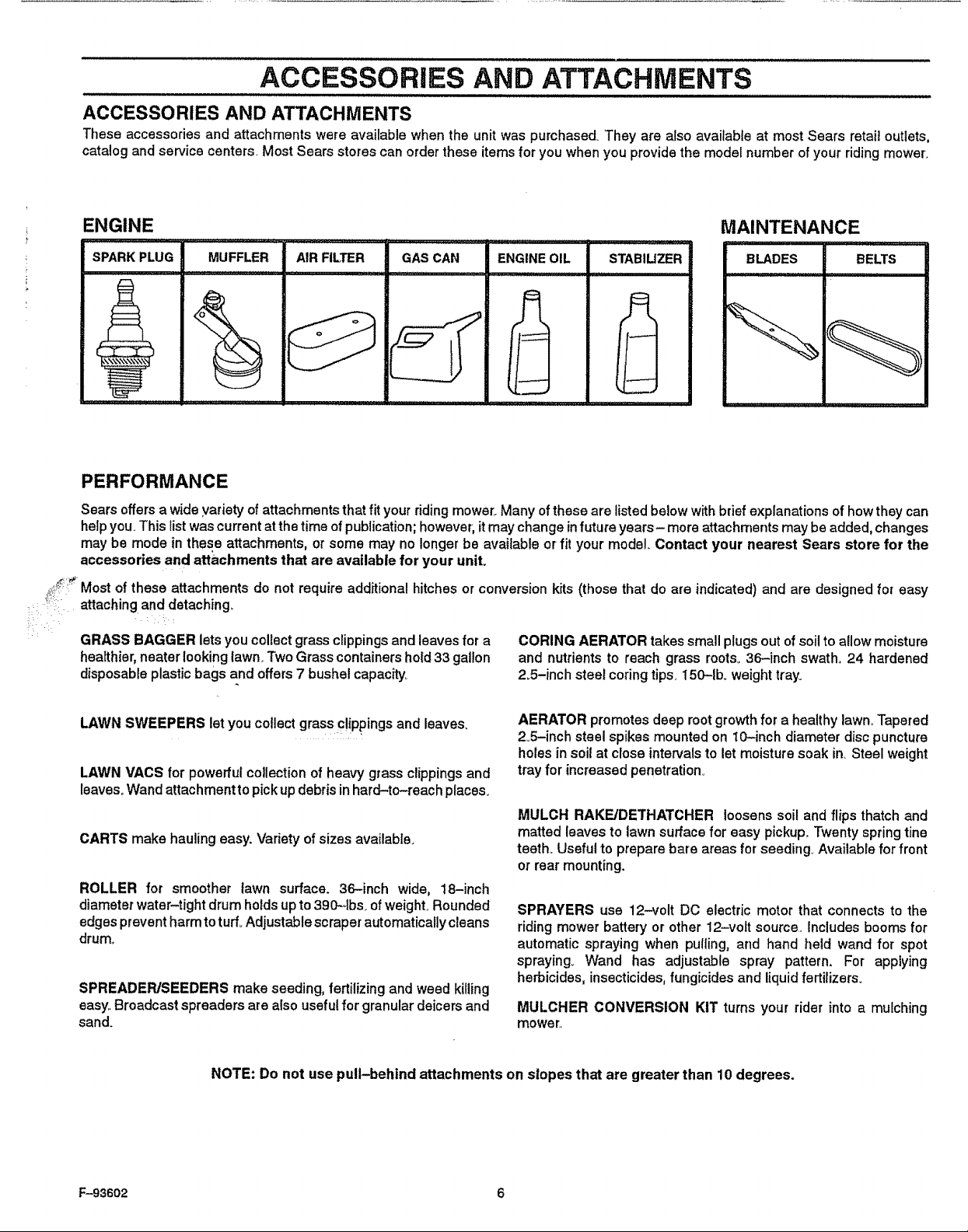
ENGINE MAINTENANCE
SPARKPLUG MUFFLER AIRFILTER GASCAN ENGINEOIL STABIUZER BLADES BELTS
; i _!_
i
E
PERFORMANCE
Sears offers a wide variety ofattachments that fit your riding mower,, Many of these are listed below with brief explanations of how they can
help you. This list was current at the time of publication; however, itmay change infuture years- more attachn'_ents may be added, changes
may be mode in these attachments, or some may no longer be available or fit your model. Contact your nearest Sears store for the
accessories and attachments that are available for your unit.
Most of these attachments do not require additional hitches or conversion kits (those that do are indicated) and are designed for easy
attaching and detaching,,
GRASS BAGGER lets you collectgrass clippingsand leavesfor a
healthier,neaterlooking lawn_Two Grasscontainershold33 gal!on
disposableplasticbagsand offers7 bushel capacity,
LAWN SWEEPERS let youcollectgrassc!!ppingsandleaves.
LAWN VACS for powerful collectionof heavy grassclippingsand
leaves°Wandattachmenttopickupdebrisinhard-to-reach places.
CARTS make hauling easy. Variety of sizes available.
ROLLER for smoother lawn surface. 36-inch wide, 18-inch
diameterwater-tightdrumholds upto390_olbs_ofweight..Rounded
edgespreventharmtoturf.Adjustable scraper automaticallycleans
drum.,
SPREADER/SEEDERS makeseeding, fertilizing andweed killing
easy.Broadcastspreaders arealso usefulfor granulardeicersand
sand.
CORING AERATOR takes small plugs out of soil to allow moisture
and nutrients to reach grass roots. 36-inch swath° 24 hardened
2_5-inch steel coring tips, 150-1b_ weight tray°
AERATOR promotes deep rootgrowthfora healthy lawn..Tapered
2.5-inch steelspikes mounted on 10-inch diameterdiscpuncture
holesinsoil atcloseintervalstolet moisturesoak in. Steel weight
trayfor increasedpenetration°
MULCH RAKE/DETHATCHER loosenssoil and flips thatchand
matted leaves to lawnsurface for easy pickup°Twentyspring tine
teeth. Usefulto preparebare areas for seeding.Available for front
or rearmounting.
SPRAYERS use 12-volt DC electric motor that connectsto the
riding mowerbatteryor other 12-volt source. Includes boomsfor
automatic spraying when pulling,and hand held wand for spot
spraying. Wand has adjustable spray pattern. For applying
herbicides, insecticides,fungicides and liquidfertilizers.
MULCHER CONVERSION KIT turnsyour rider into a mulching
mower.
NOTE: Do not use pull-behind attachments on slopes that are greater than 10 degrees.
F-93602 6
ASSEMBLY
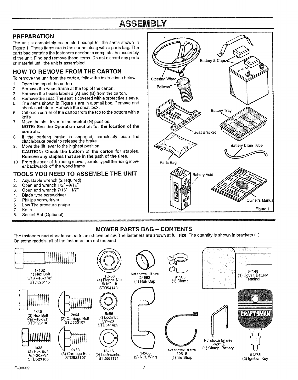
PREPARATION
The unit is completely assembled except for the items shown in
Figure 1. These items are in the carton along with a parts bag. The
parts bag contains the fasteners needed to complete the assembly
of the unit, Find and remove these items Do not discard any parts
or material until the unit is assembled.
HOW TO REMOVE FROM THE CARTON
To remove the unit from the carton, follow the instructions below,.
1.. Open the top of the carton°
2_ Remove the wood frame at the top of the carton_
3, Remove the boxes labeled (A) and (B) from the carton,,
4, Remove the seat..The seat is covered with a protective sleeve,
5 The items shown in Figure 1 are in a small box, Remove and
check each item Remove the small box
6. Cut each corner of the carton from the top to the bottom with a
knife,
7, Move the shift lever to the neutral (N) position°
NOTE: See the Operation section for the location of the
controls.
8 If the parking brake is engaged, completely push the
clutch/brake pedal to release thebrake,
9. Move the lift lever to the highest position
CAUTION: Check the bottom of the carton for staples.
Remove any staples that are in the path of the tires,,
10., From the back ofthe riding mower, carefully pull the riding mow-
er backwards off the wood frame.,
TOOLS YOU NEED TO ASSEMBLE THE UNIT
t. Adjustable wrench (2 required)
2. Open end wrench t/2" -9/16"
3o Open end wrench 7/16"-1/2"
4., Blade type screwdriver
5, Phillips screwdriver
6 Low Tire pressure gauge
7. Knife
& Socket Set (Optional)
Steedng Whee
Battery Drain Tube
Parts Bag
/
Figure 1
MOWER PARTS BAG - CONTENTS
The fasteners and other loose parts are shown below, The fasteners are shown at full size The quantity is shown in brackets ().
On soma models, all of the fasteners are not required,
ltlttltlllll/llll
@
(1) Hex Bolt No!shownfullsize
5/I 6"--18Xt_/2'' 24582 91565
STD523t t5 (4) HubCap (1) Ctamp
t 5x88
(4) Flange Nut
5116'-18
STD54t431
@
Ix45
(2) Hex Bolt
S!l6"-18X5/8 "
STD523t06
2x64
(2) Carriage Bolt
STD533 t07
,iiiiiiiiiiii
lx38
(2) Hex Bolt
V4'%20XS/8 ''
STD5231O6
F-93602 7
2x53
(3) Carriage Bolt
STD533107
t 5x66
(4) Locknut
_14"-20
STD541425
@
18x16
(2) Lockwasher
STD55t13t
14X86
(2) Nut, Wing
Not shown lull size
32618
(1)Tie Strap
Notshown lull size
56205Z
(t) Clamp, Battery
54148
(1) Cover, Battery
Terminal
91275
(2) Ignition Key
ASSEMBLY
HOW PREPARETO AND CHARGE THE
BATTERY 4_ Wait 20 to30 minutesbeforeyou putthe vent caps on the
WARNING: Read the instructions included with the
battery acidcontainer° Protectyour hands andeyes
from the battery acid° Use clothing that will protect
you.
DANGER
BATTERY ACID WILL
CAUSE SEVERE BURNS
Contains sulfuric aci&
Do not let the battery acid come in
contact with skin, eyes, or clothing.
To prevent accidents, neutralize the battery acid that was not
used,. To neutralize, fill the container half full with water, Add
baking soda and mix using a piece of wood until the solution
does not foam, Discard the solution and wash the container
with water° Destroy the container.
ANTIDOTE:
External - Wash the area with water, then wash with a solu-
tion of water and sodium bicarbonate.
Internal - Drink large amounts of water, milk, or milk of mag-
nesia,. Drink water mixed with the whites of eggs. Call a Doctor
immediately,
Eyes - Flush with water for 15 minutes and then get immedi-
ate medical help..
POISON
KEEP AWAY FROM CHILDREN
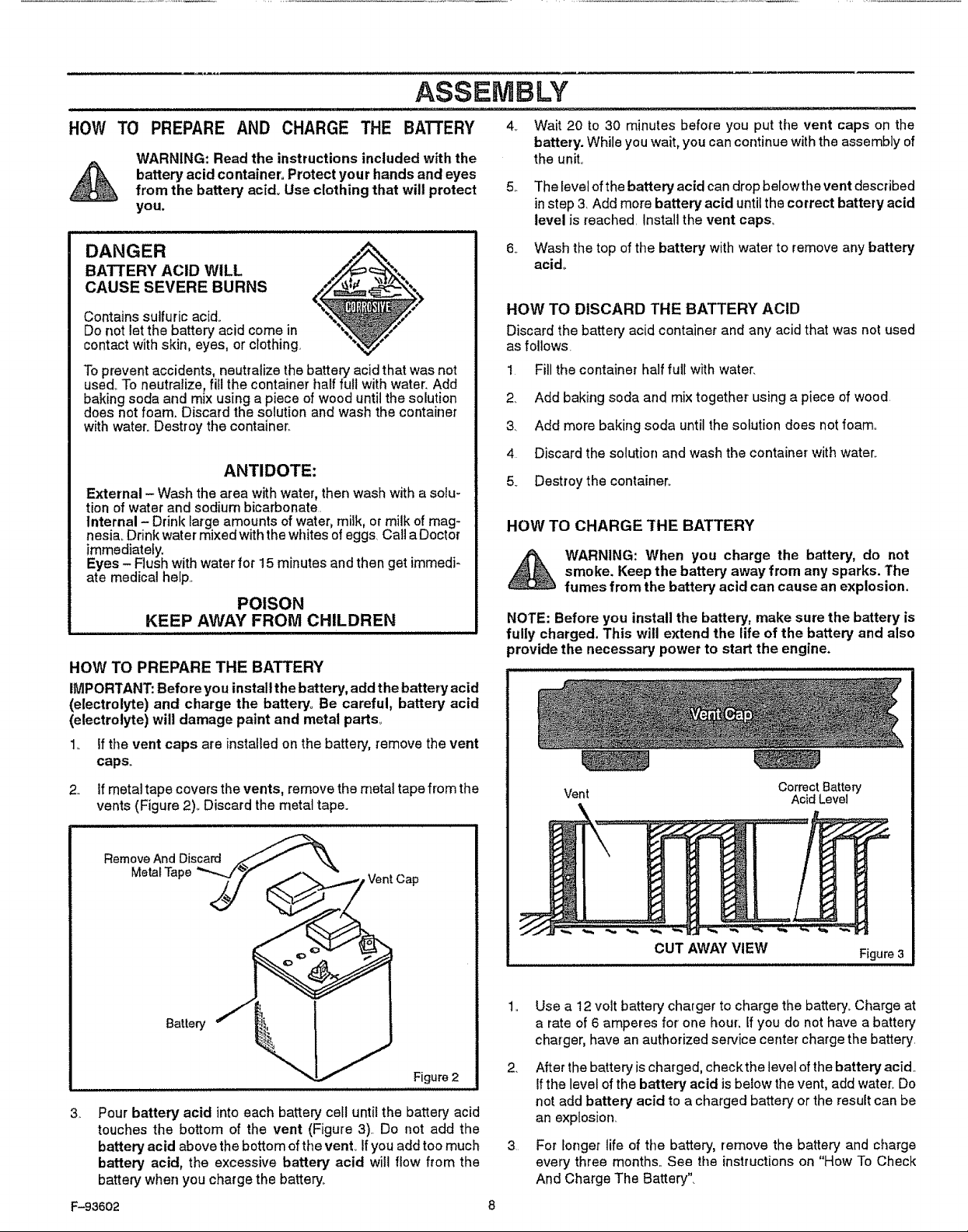
HOW TO PREPARE THE BATTERY
IMPORTANT: Before you install the battery, add the battery acid
(electrolyte) and charge the battery. Be careful, battery acid
(electrolyte) will damage paint and metal parts.
1. Ifthe vent caps are installed on the battery, remove the vent
caps.
If metal tape covers the vents, remove the metal tape from the
,,
vents (Figure 2)., Discard the metal tape.
battery. While you wait, you can continue with the assembly of
the unit,
5,.
The level of the battery acid can drop belowthe vent described
in step 3. Add more battery acid until the correct battery acid
level is reached. Install the vent caps,
6_
Wash the top of the battery with water to remove any battery
acid_
HOW TO DISCARD THE BATTERY ACID
Discard thebattery acidcontainerand any acid that wasnot used
as follows,
I Fill the container half full with water.
2. Add baking soda and mix together using a piece of wood
3. Add more baking soda until the solution does not foam..
4 Discard the solution and wash the container with water..
5. Destroythe container..
HOW TO CHARGE THE BATTERY
smoke. Keep the battery away from any sparks. The
WARNING: When you charge the battery, do not
fumes from the battery acid can cause an explosion.
NOTE: Before you install the battery, make sure the battery is
fully charged. This will extend the life of the battery and also
provide the necessary power to start the engine.
Vent
Correct Battery
Acid Level
Remove And Discard ._--_\
MetalTape '_.z'_,; f _ _ - VentCap
i i ii q ii uuHi ,ul ,,ll,,i,ill
3.
Pour battery acid into each battery cell until the battery acid
_ Figure 2
touches the bottom of the vent (Figure 3) Do not add the
battery acid above the bottom ofthe vent., Ifyou add too much
battery acid, the excessive battery acid will flow from the
battery when you charge the battery°
F-93602 8
CUT AWAYVIEW
.
Use a 12 volt battery charger to charge the battery. Charge at
a rate of 6 amperes for one hour, if you do not have a battery
charger, have an authorized service center charge the battery.
2,
After the battery is charged, check the level of the battery acid_
Ifthe level of the battery acid is below the vent, add water_ Do
not add battery acid to a charged battery or the result can be
an explosion,
3
For longer life of the battery, remove the battery and charge
every three months.. See the instructions on "How To Check
And Charge The Battery".
Figure 3
ASSEMBLY
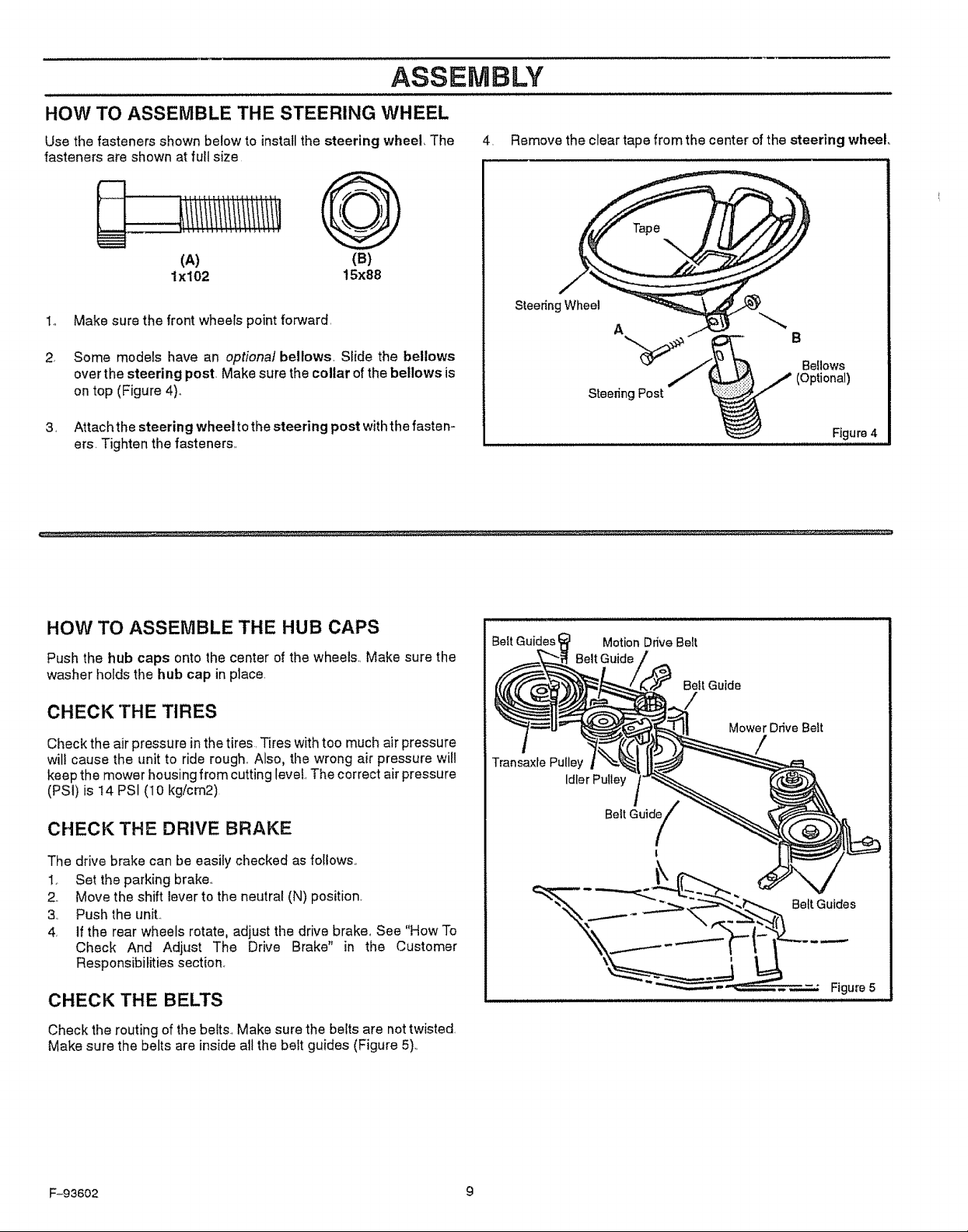
HOW TO ASSEMBLE THE STEERING WHEEL
Use the fasteners shown below to installthe steering wheel The
fasteners are shown at full size
4 Remove the clear tape from the center of the steering wheel
(A)
lx102
1o Make sure the front wheels point forward
2 Some models have an optional bellows Slide the bellows
over the steering post Make sure the collar of the bellows is
on top (Figure 4)°
3 Attach the steering wheel to the steering post with the fasten-
ers Tighten the fasteners
(B)
15x88
HOW TO ASSEMBLE THE HUB CAPS
Push the hub caps onto the center of the wheel& Make sure the
washer hofds the hub cap in place
CHECK THE TIRES
Check the air pressure in the tires Tires with toe much air pressure
will cause the unit to ride rough Also, the wrong air pressure witl
keep the mower housing from cutting level The correct air pressure
(PSi) is !4 PSI (10 kg!cm2)
CHECK THE DRIVE BRAKE
SteeringWheel
A
Bellows
(Optional)
Steering Post
Figure 4
BeitGuidesi MotionDrive Beit
BeltGuide
Bell Guide
Mower Drive Belt
/
Transaxle Pulley
Idler Pulley
Belt Guide
The drive brake can be easily checked as follows
1 Set the parking brake
2 Move the shift lever to the neutral (N) position
3 Push the unit
4 If the rear wheels rotate, adjust tile drive brake. See "How To
Check And Adjust The Drive Brake" in the Customer
Responsibilities section
CHECK THE BELTS
Check the routing of the beits., Make sure the belts are not twisted,
Make sure the belts are inside all the belt guides (Figure 5)
F-93602 9
Figure 5
ASSEMBLY
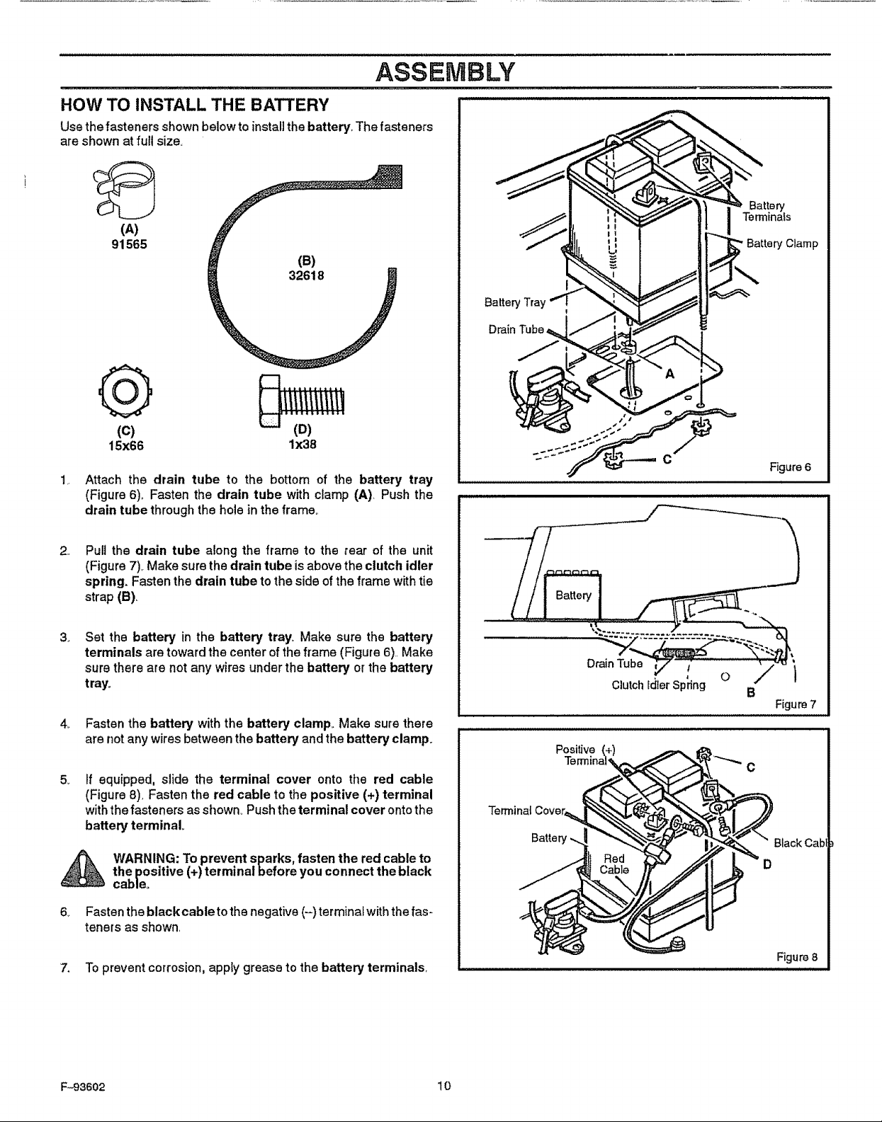
HOW TO INSTALL THE BATTERY
Use thefasteners shown below to install the battery, The fasteners
are shown at full size.
(A)
91565
(B)
32618
Q
(c)
15x66 lx38
Attach the drain tube to the bottom of the battery tray
(Figure 6)° Fasten the drain tube with clamp (A), Push the
drain tube through the hole in the frame,,
BatteryTray
Battery Clamp
i
C
Figure 6
2,_
Pull the drain tube along the frame to the rear ofthe unit
(Figure7),.Make surethedrain tube isabove theclutch idler
spring. Fastenthedrain tube totheside ofthe framewithtie
strap(B).
3_
Set the battery in the battery tray. Make sure the battery
terminals are toward the center of the frame (Figure 6)..Make
sure there are not any wires under the battery or the battery
tray.
4_ Fasten the battery with the battery clamp. Make sure there
are not any wires between the battery and the battery clamp.
5_
If equipped, slide the terminal cover onto the red cable
(Figure8), Fastenthe red cable tothe positive (+) terminal
withthefasteners asshown. Pushtheterminal cover ontothe
battery terminal
_ WARNING: To prevent sparks, fasten the red cable to
6_ Fasten the black cable to the negative (-) terminal with the fas-
the positive (+) terminal before you connect the black
cable°
tenets as shown.
Terminal Cover
Batter
Drain Tube 1
Clutch Ic[lerSp_ng O
Positive
B
Figure 7
BlackCab
D
7. To prevent corrosion, apply grease to the battery terminals.
F-93602 10
ASSEMBLY
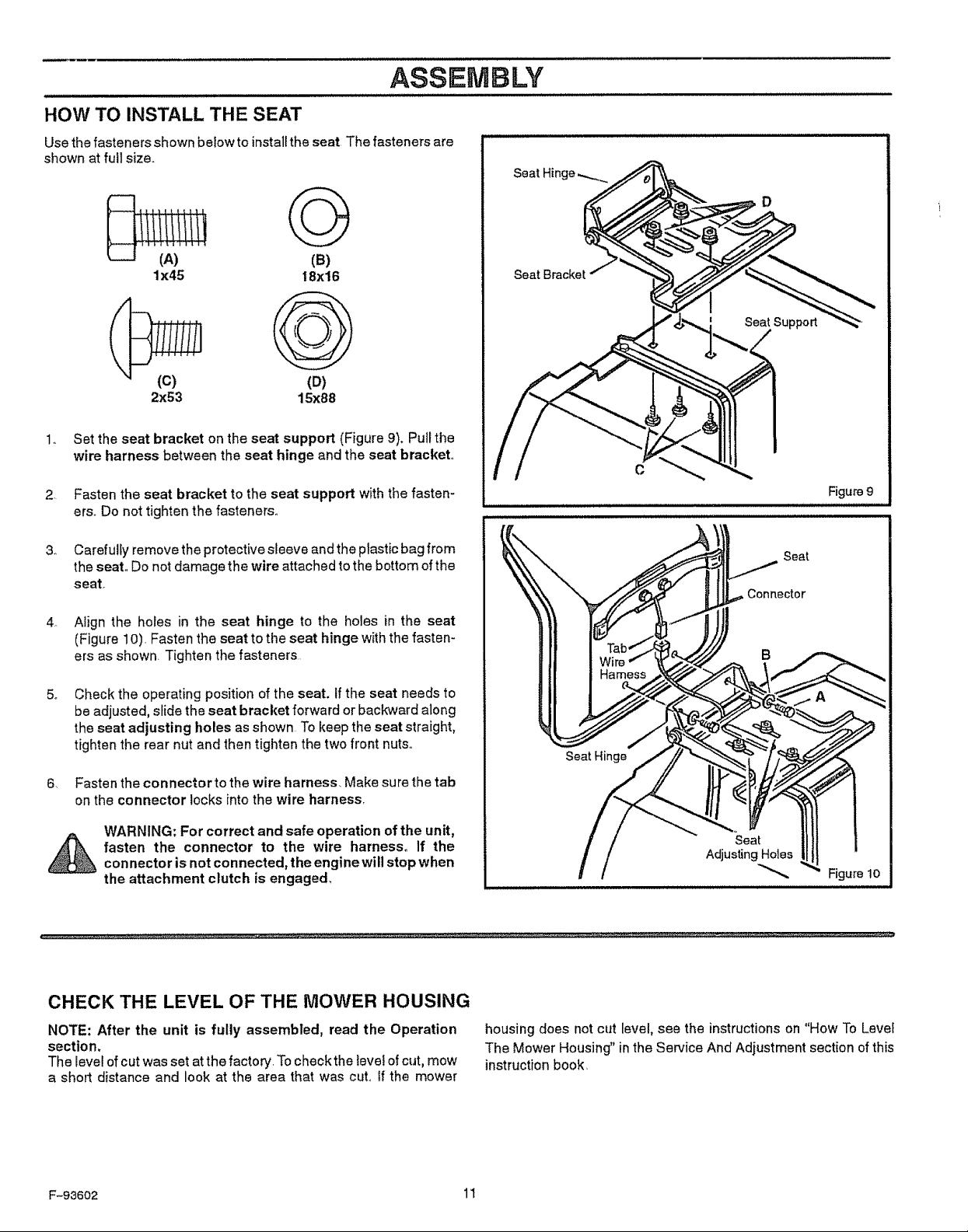
HOW TO INSTALL THE SEAT
Use the fasteners shown below to install the seat The fasteners are
shown at full size
G
(e)
1x45 I8x16
D
Seat Bracket
2x53 15x88
(D)
1.
Set the seat bracket on the seat support (Figure 9). Pull the
wire harness between the seat hinge and the seat bracket
2.
Fasten the seat bracket to the seat support with the fasten-
erso Do not tighten the fasteners
3_
Carefully remove the protective sleeve and the plastic bag from
the seat Do not damage the wire attached to the bottom of the
seat
4_
Align the holes in the seat hinge to the holes in the seat
(Figure 10) Fasten the seat to the seat hinge with the fasten-
ers as shown Tighten the fasteners
5_
Check the operating position of the seat. If the seat needs to
be adjusted, slide the seat bracket forward or backward along
the seat adjusting holes as shown To keep the seat straight,
tighten the rear nut and then tighten the two front nuts
Fasten the connector to the wire harness Make sure the tab
6_
on the connector locks into the wire harness
WARNING: For correct and safe operation of the unit,
fasten the connector to the wire harness If the
con nector is not connected, the engine will stop when
the attachment clutch is engaged.
C
Figure9
Seat
Seat Hinge
Figure lO
CHECK THE LEVEL OF THE MOWER HOUSING
NOTE: After the unit is fully assembled, read the Operation
section.
The level of cut was set at the factory Tocheck the level of cut, mow
a short distance and look at the area that was cut° if the mower
F-93602 11
housing does not cut level, see the instructions on "How To Levet
The Mower Housing" in the Service And Adiustment section of this
instruction book,
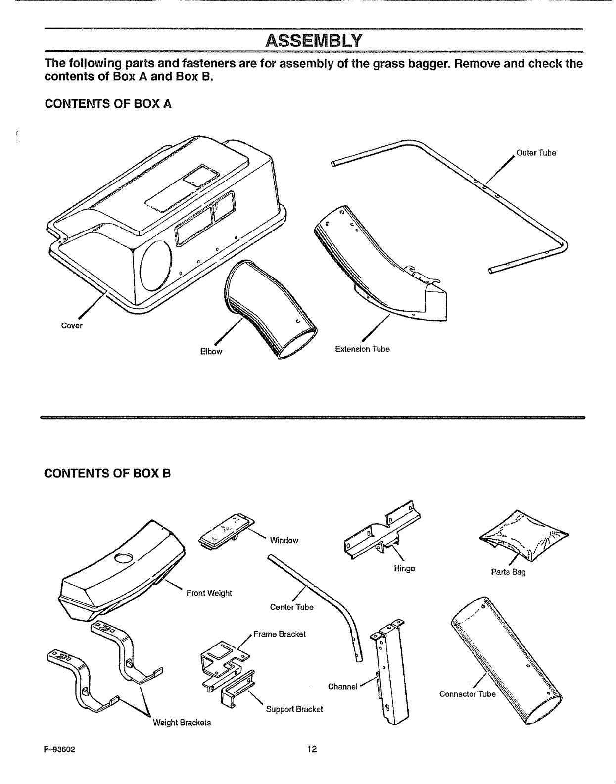
ASSEMBLY
The following parts and fasteners are for assembly of the grass bagger. Remove and check the
contents of Box A and Box B.
CONTENTS OF BOX A
CONTENTS OF BOX B
Elbow
FrontWeight
Window
Center Tube
/
ExtensionTube
Hinge
PartsBag
0 Frame Bracket
Support Bracket
WeightBrackets
F-93602 12
Channel
Co
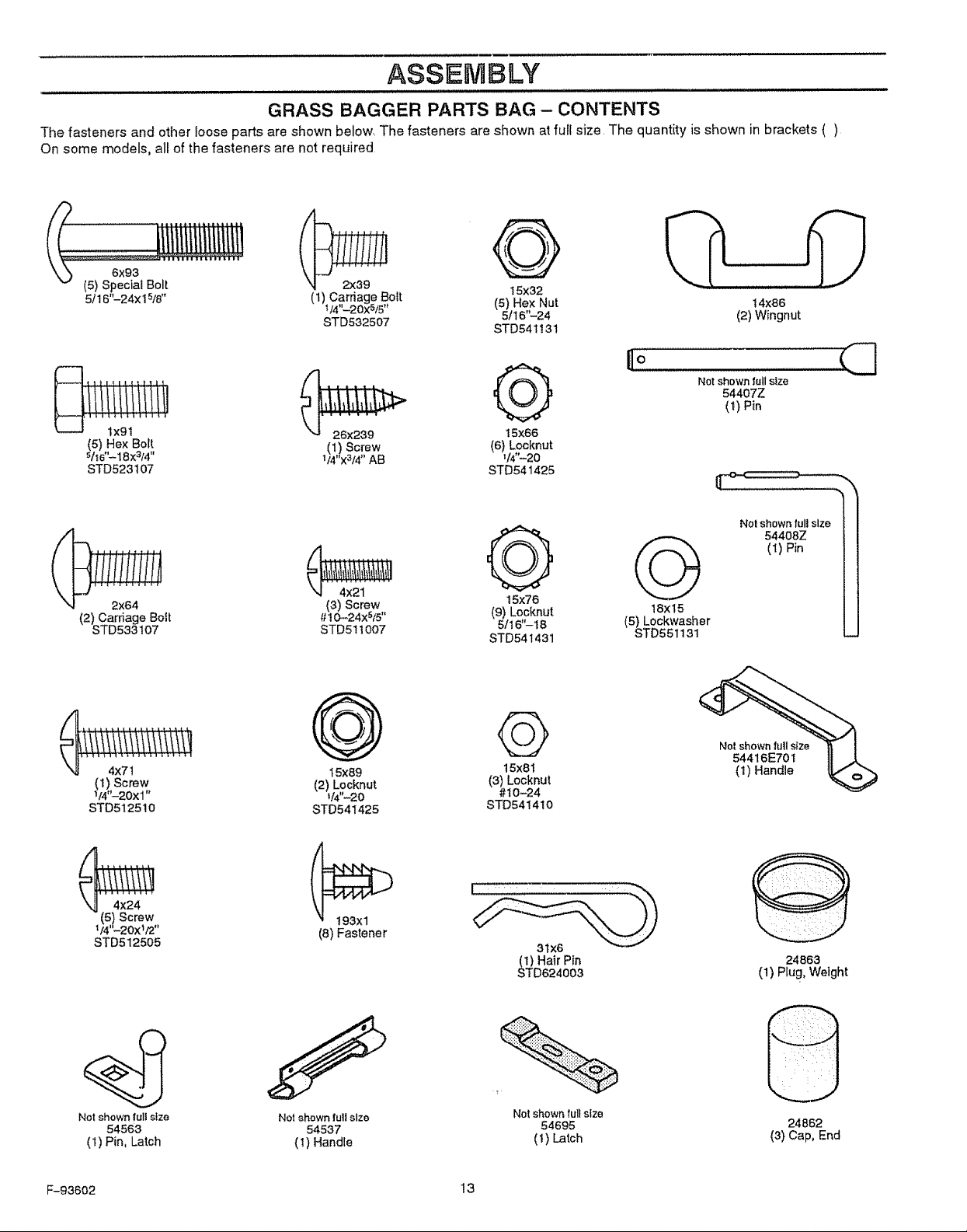
ASSEMBLY
GRASS BAGGER PARTS BAG - CONTENTS
The fasteners and other loose parts are shown below. The fasteners are shown at full size The quantity is shown in brackets ( )
On some models, all of the fasteners are not required
5/16"-24xl 5/8" (1)V4,,_20x5i5''Carriage Bott (5) Hex Nut 14x86
STD532507 5/16 -24 (2) Wingnut
26x239 t5X66
(5) Hex Bolt (1) Screw (6) Locknut
s/_6"-18x3/4" 1/4'_3_" AB V4"-20
STD523107 STD541425
2x64 (3) Screw
(2) Carriage Bolt #t0-24xS/5"
STD533t07 STD51t007
STD541131
Q
15X76
(9) Locknut
51t6"-18
STD541431
G
18x15
(5) Lockwasher
STD551131
Notshown fell size
54407Z
(t) Pin
Notshown full size /
54408Z
(1) Pin
C
!
I
i
Q
4x71
(1) Screw
1/4,__20xl.
STD512510
STD512505
Net shown full s_ze
54563
(I) Pin, Latch
F-93602 13
Notshownlultsize
15x89
(2) Locknut
_/4"-20
STD541425
(8) Fastener
54537
( 1) Handle
©
t5x8 t
(3) Locknut
#t 0-24
STD541410
3tX6
) Hair Pin
D624003
Notshown full size
(I) Latch
54695
Not shown full size
54416E70 t
(1) Handle
24863
(1) Plug, Weight
24562
(3) Cap, End
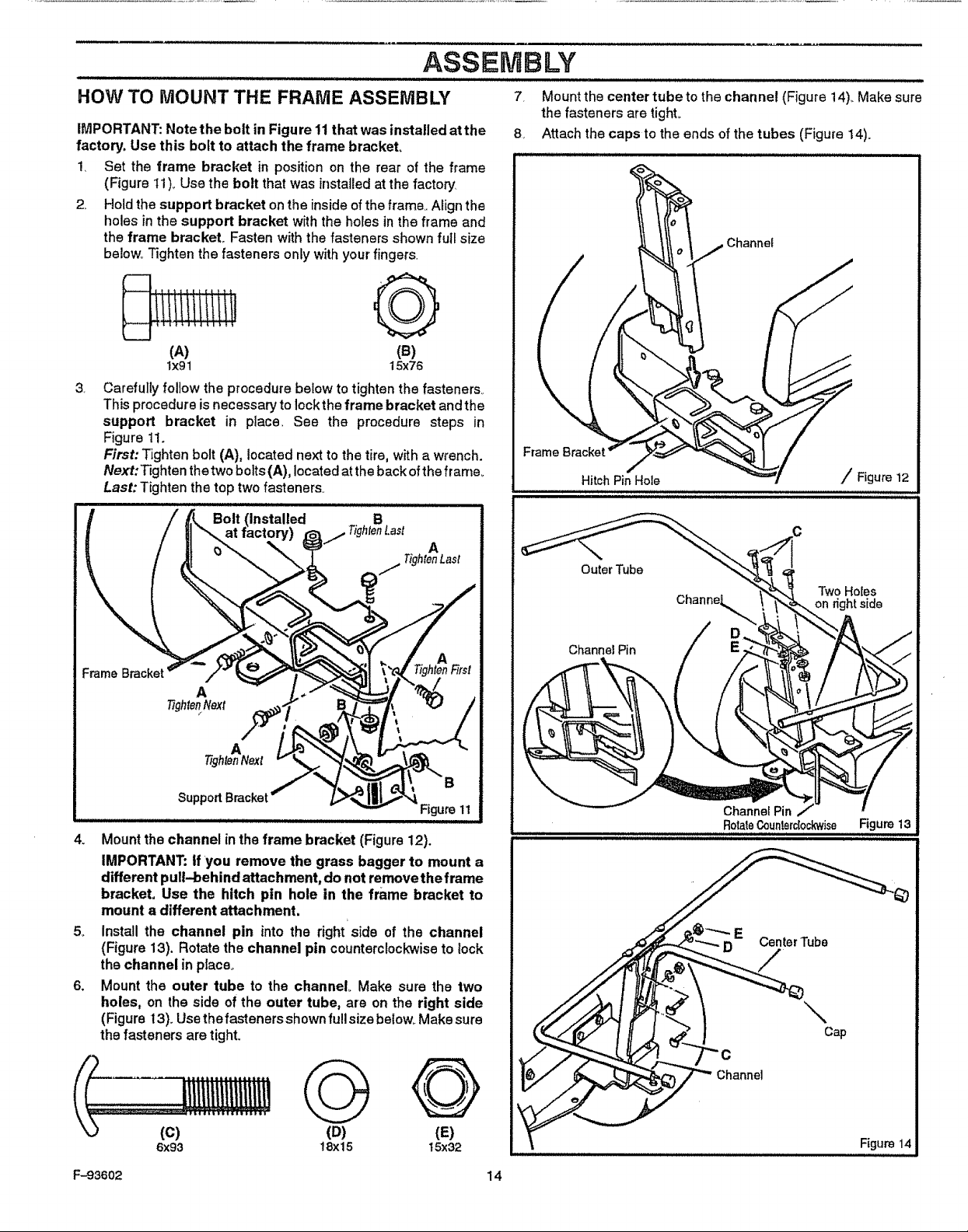
ASSEMBLY
HOW TO MOUNT THE FRAME ASSEMBLY
iMPORTANT: Note the bolt in Figure 11 that was installed at the
factory. Use this bolt to attach the frame bracket,
1, Set the frame bracket in position on the rear of the frame
(Figure I1)_ Use the bolt that was installed at the factory
2,, Hold the support bracket onthe inside of the frame,, Align the
holes in the support bracket w_th the holes in the frame and
the frame bracket_ Fasten with the fasteners shown full size
below° Tighten the fasteners only with your fingers,
(A) (e)
1x91 15x76
3,
Carefully followtheprocedure below totightenthefasteners.
Thisprocedure isnecessary to locktheframe bracket andthe
support bracket in place, See the procedure steps in
Figure11.
First:Tightenbolt (A), locatednexttothe tire,withawrench.
Next:_ghten thetwo bolts (A),locatedat thebackoftheframe..
Last: Tightenthetoptwofasteners°
installed
7. Mount the center tube to the channel (Figure 14)_Make sure
the fasteners are tighL
8, Attach the caps to the ends of the tubes (Figure 14).
Channe_
Frame
Hitch Pin Hole / Figure 12
A
TightenNext
A
"tightenNext
SupportBracket
4. Mount the channel in the frame bracket (Figure12).
IMPORTANT: tf you remove the grass bagger to mount a
different pull-behind attachment, do not removethe frame
bracket, Use the hitch pin hole in the frame bracket to
mount a different attachment.
5_ Installthe channel pin into the tight'side of the channel
(Figure 13). Rotatethe channel pin counterclockwiseto lock
thechannel in place.
6. Mountthe outer tube to the channel. Make sure the two
holes, on the side of the outer tube, are onthe right side
(Figuret3)_Usethefastenersshownfull sizebelow. Makesure
thefastenersaretight.
Outer Tube
Two Holes
Channel Pin
RotaleCoun!erclockwise Figure13
Center Tube
\
Cap
G Q
(D) (E)
18x15 15x326x93
F-93602 14
Channel
Figure 14
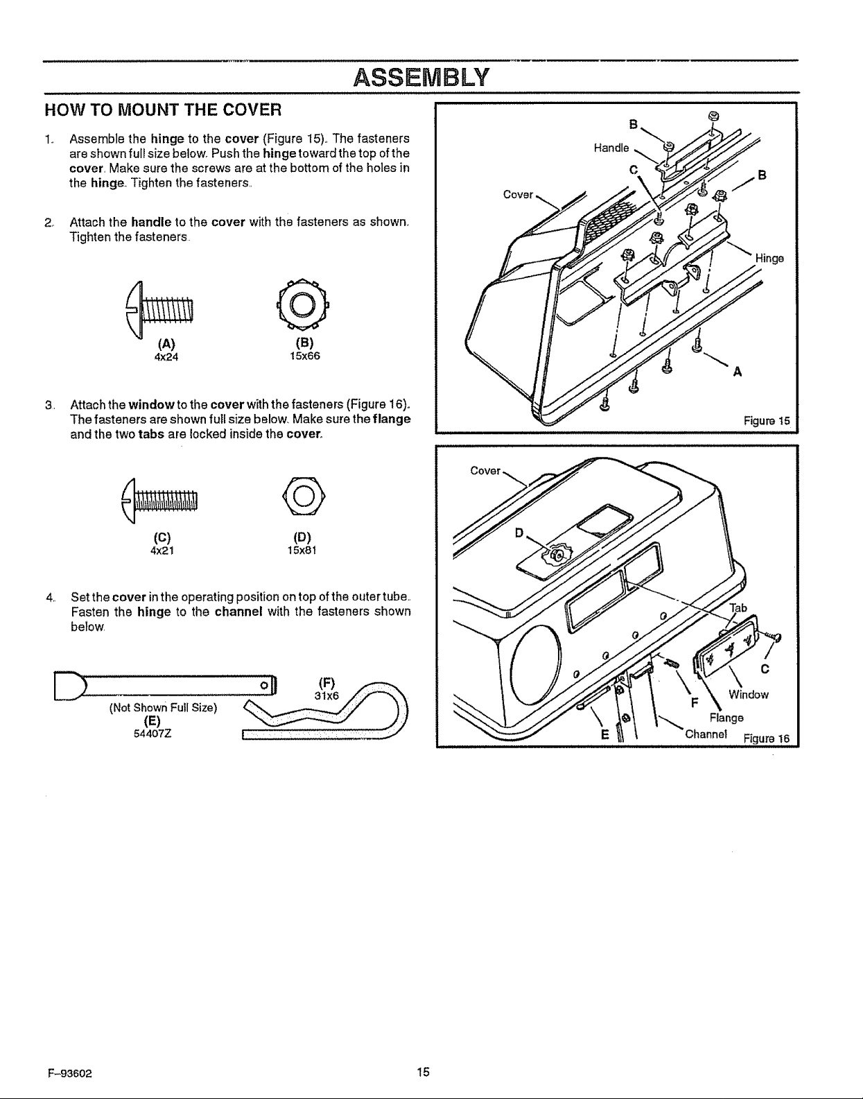
ASSEMBLY
HOW TO MOUNT THE COVER
Assemble the hinge to the cover (Figure 15)_The fasteners
are shown full size belowr Push the hinge toward the top of the
cover, Make sure the screws are at the bottom of the holes in
the hinge. Tighten the fasteners.,
2o Attach the handle to the cover with the fasteners as shown,
Tighten the fasteners
Q
(A)
4x24
3, Attach the window to the cover with the fasteners (Figure 16)o
The fasteners are shown full size below_ Make sure the flange
and the two tabs are locked inside the cover.
(B)
15x66
©
@
Handle
C
ge
A
Figure 15
(c) (D)
4x21 15x8t
,,
Set the cover inthe operating position on top of the outer tube,,
Fasten the hinge to the channel with the fasteners shown
below.
D
(Not shownFullSize)
(E)
54407Z
Tab
F-93602 15
 Loading...