

Craftsman 502254152 Owner’s Manual
owners
a a
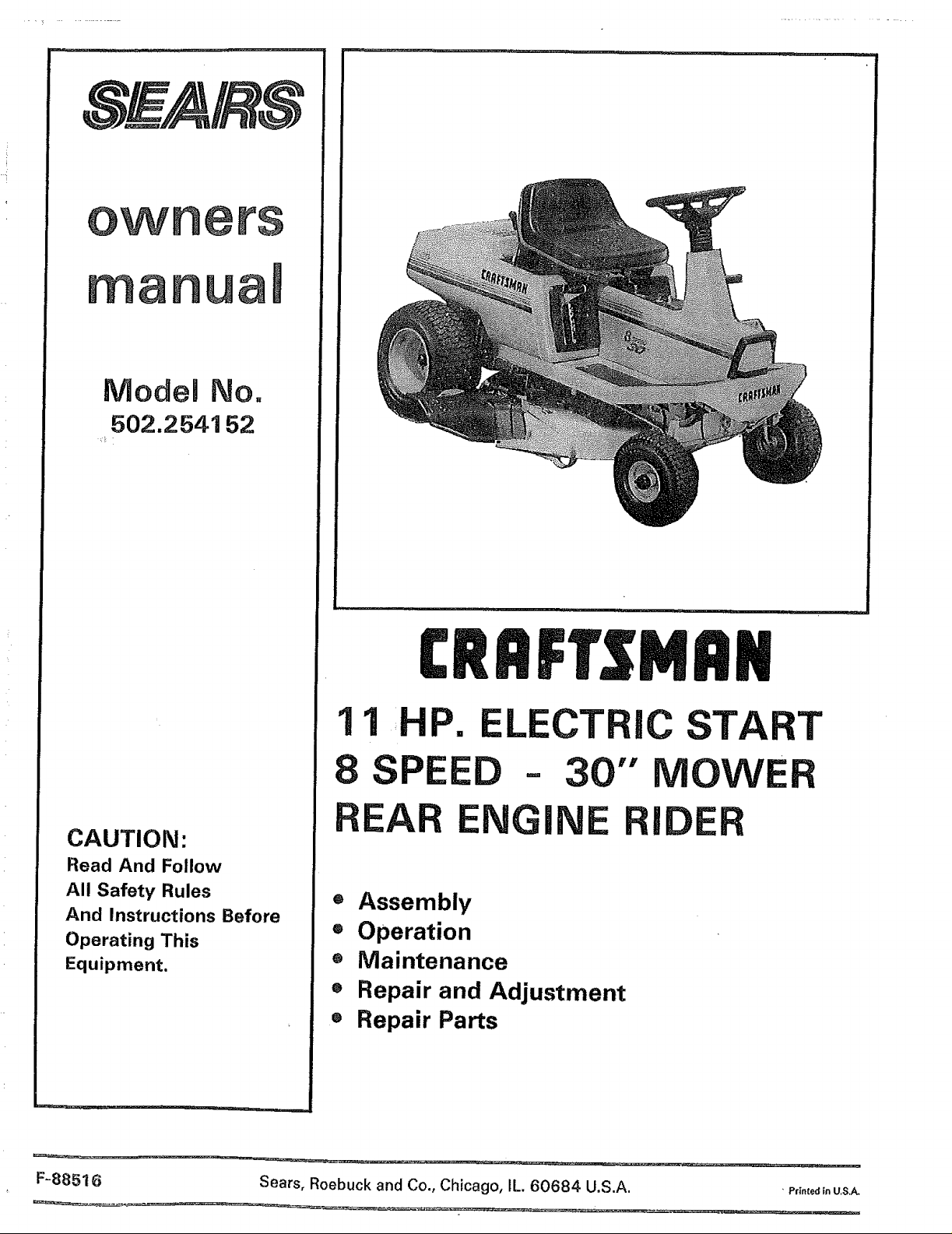
Model No.
502.2541 52
CAUTION:
Read And Follow
All Safety Rules
And Instructions Before
Operating This
Equipment.
11 P. LECTRIC START
8 SPEED = 30" MOWER
EA ENG! I
® Assembly
® Operation
• Maintenance
o Repair and Adjustment
® Repair Parts
F-88516 Sears, Roebuck and Co., Chicago, IL. 60684 U.S.A.
• PrTnted fn U,S,A.

SAFETY RULES
Safe Operation Practices for Riding Vehicles
As Recommended by American National Standards Institute
1. Know the controls and how to stop quickly, READ THIS
INSTRUCTION BOOK and any instructions furnished with
attachments.
2. Do not allow children to operate the machine. Do not allow
adults to operate tt without proper instruction.
3, Clear the work area of objects (wire, rocks, etc.) which might
be discharged by the machine,
4. Handle gasoline with care, It is highly flammable.
a. Use an approved gasoline container.
b. Never remove the fuel cap or add gasoline to a running
orhot engine oran engine that has not been allowed to cool
for several minutes after running, Never fill the fuel tank
indoors. Clean up spilled gasoline.
c. Do not run the engine indoors. Exhaust fumes are
dangerous,
5. Always wear safety glasses or a eye shield when you operate
the unit to protect your eyes from foreign objects that can be
thrown from the unit, Always wear eye protection when you
make an adjustment or repairs to the unit.
6. Keep all nuts, bolts, and screws tight to be sure the equip-
ment is in safe working condition.
7, Disengage all attachment clutches and shift into neutral
before attempting to start the engine,
8. Disengage power attachment(s) when transporting or not
in use.
9, Do not stop or start suddenly when going uphil] ordownhill,
Mow upand down the face of steep slopes;never across the
face, See the "Guide" in the back this book to check for
safe operation,
1O, Reduce speed and exercise extreme caution on slopes and in
sharpturns to prevent tipping or loss of control. Beespecially
cautious when changing directions on slopes.
11, Stay alert for holes, rocks, roots in the terrain, and other
hidden hazards, Keep away from drop-offs,
12. Use care when pulling loads or using heavy equipment.
a. Use only approved drawbar hitch points.
b. Limit loads to those you can safety control.
c, Do not turn sharply. Use care when baektng,
d, Use counterweight(s) or wheel weights when suggested
in the instruction book.
13. Watch out for traffic when crossing or near roadways.
14. When using any atiachments, never direct discharge of
material toward bystanders or allow anyone near the unit
while in operation.
15. Disengage power to attachment(s) and stop the engine
before 1eaving the operator's position.
16. To reduce fire hazards, keep the engine free of grass, leaves,
or excessive grease.
17, The vehicle and attachments must bestopped and inspected
for damage after striking a foreign object, All damage must
be repaired before restarting and operating the equipment.
18, Donot change the engine governorsettings oroverspeed the
engine.
19. When using the vehicle with a mower, proceed as follows:
a. Mow only in daylight or tn good a_ifieiat light2
b, Never make a cutting height adjustment while the
engine is running if the operator must dismount.
c. Stop the engine before removing a grass catcher or
unclogging the chute,
d. Check the blade(s) and mounting nut(s) for proper tight-
ness at frequent intervals, Frequently check the blade for
wear or damage such as cracks and nicks, A blade that is
bent or damaged must be immediately replaced with a
factory replacement blade. For safety, replace the blade
every two years, Frequently check the nut(s) that hold the
blade(s). Replace damaged nuts and tighten loose nuts, ,'
20. Disengage power to the mower before backing up. Do not
mow in reverse unless absolutely necessary and then only
after careful observation of the entire area behind the
mower.
21. Under normal usage, the grass catcher bag material" is
subject to deterioration and wear. It should be checked
frequently for bag replacement. Replacement bags should be
checked to ensure compliance with the original manufac-
turers recommendations or specifications.
22. Donot operate the mowerwithout either the grass catcher or
guards in place, Read the instructions provided with the
grass catcher.
23, Do not carry passengers, Do not mow when children and
others are present.
24. Never store the equipment with gasoline in the tank inside a
building where fumes may reach an open flame or spark.
Allow the engine to cool before storing in any enclosure.
25. Take atl possible precautions when leaving the vehicle
unattended, such as disengaging the blade engagement _
control lever, lowering the attachment(s), shifting into neutral,
setting the parking brake, stopping the engine, and removing
the key.
26, Keep the vehicle and attachments in good operating condi-
tion, and keep safety devices in place and working,
27. Disengage power to attachment(s) and stop the engine
before making any repairs or adjustments, The carburetor
can be adjusted with the engine running.
28, Wa!!; for all movement to stopbefore servicing any part ofthe
29, ;:;Read and follow the instructions in this book concern ng
safety, and op§ration of the mower.
WARNING: This unit is equipped with an internal combustion engine and must not be used on or near any unimproved forest-covered,
brush-covered or grass-covered land unless the engine's exhaust system isequipped with a spark arrester meeting applicable local or state
laws (if any), If a spark arrester is used, it must be maintained in effect!re working order by the operator,
In the State of California the above is required by law (Section 4442 of the California Public Resources Code), Other states may have similar
laws, Federal laws apply on federal lands, See an Authorized Service Center for a spark attester for the muffler,
precautions. It means: "Attentionl Become Alertl
Look for this symbol to point out important safety
Your Safety Is Involved/p
F-88516
This product is made to give you many hours of performance and
safe operation. To keep the unit in good condition, you must
correctly service the unit. For safety and performance, follow the
ASSEMBLY, OPERATION, and MAINTENANCE instructions. If you
can not correct a problem, see the nearest Sears Service Center.
CUSTOMER RESPONSIBILITIES
Follow all the assembly instructions. Correctly adjust the unit.
Carefully read and foltow the rules for safe operation. Inspect the
unit, Complete all maintenance on the unit, Know how to operate
all standard and accessory equipment on the unit, Make sure that
the operator can correctly operate the unit. Operate the unit only
with guards, shields, and other safety items in place and working
correctly. Service the unit only with authorized or approved
replacement parts,
RIDING LAWN MOWER
Record inthe space below the serial number and the date
of purchase of this unit.
The model number and serial number are found under the
seat on a plate attached to the seat support.
REAR ENGINE RIDER FEATURES
Craftsman Engine Air cooled and long life with solid state
ignition.
All Gear Transmission Eight forward speeds and one reverse
to let you select the correct speed for your type of yard. A drive
chain connects the transmission to an automotive type
differential.
Tilt Seat The seat tilts forward for easy access to the battery
and the engine,
Side Panels The side panels can be easily removed for access
to the engine. •
Mower Housing The full-floating suspension and single blade
give an even cut. The lift lever has an eight position height
adjustment.
ATTACHMENTS
This unit can useattachments available at the nearest Sears Store.
This unit can pull attachments like a lawn sweeper, a lawn aerator,
or a hopper spreader, This unit can not use attachments that
engage the ground like a plow, a disk harrow, or a cultivator.
Serial Number:
Date of Purchase:
Keep these numbers for future reference,
MAINTENANCE AGREEMENT
A Sears Maintenance Agreement Isavailable on this unit. See the
nearest Sears Store for information.
LIMITED TWO YEAR WARRANTY ON ELECTRIC START RIDING EQUIPMENT
Fortwo years fromthe dateof purchase,when thisridingequipment is maintained, lubricated, and tuned up accordingto the operating
and maintenance instructions in the Owner's Manual, Sears will repair free of charge any defect in material or workmanship in this
electric start riding equipment.
Thiswarranty excludesblade(s),blade adapter(s}, sparkplug(s),air cleaner, and belt(s),which are expendableand become worn during
normal use.
This warranty does not cover:
- tire replacement or repair caused by punctures from outside objects (such as nails, thorns, stumps, or glass);and
- repairs necessary because of operator abuse or negligence, including the failure to maintain the equipment according to
instructions contained in the Owner's Manual; and
- riding equipment used for commercial or rental purposes.
FULL 90-DAY WARRANTY ON BATTERY
For 90 days from the date of purchase, if any battery included with this riding equiPment proves defective in material or workmanship
and our testing determines the battery will not hold a charge, Sears will replace th_ battery at no charge,
WARRANTY SERVICE IS AVAILABLE BY CONTACTING THE NEAREST SEARS SERVICE CENTEP_'DEPARTMENT IN THE UNITED
STATES. This warranty applies only while this product is in use in the United States.
This warranty gives you specific legal rights, and you may also have other rights which vary from state to state.
Sears, Roebuckand Co,, D/698-731A, Sears Tower, Chicago,tL 60684
F-88516 3
INDEX
A
Adjustments:
Blade Engagement Control .............. 15
Brake, Drive .........................................25
Carburetor ...........................................29
Chain, Front Drive ..............................26
Chain, Rear Drive ...............................27
Mower Housing, Level ......................22
Throttle Control Cable .......................29
Assembly ..........................................5 - 10
Attachments ...............................................3
B
Battery:
Charge ....................................................7
Clean and Check ................................ 18
Emergency Start ................................30
Install ....................................................10
Storage ................................................30
Belt;
Motion Drive, Replace .......................21
Mower Drive, Adjust .......................... 15
Mower Drive, Replace .......................21
Blade, Remove and Install ..................... 16
Blade, Sharpen .........................................17
Blade Engagement Control'.
Adjust ...................................................15
Operation .............................................11
Brake Pedal, Operation ........................... 11
C
Carburetor, Adjust ...................................29
Chains, Check and Adjust ............... 26, 27
Charge Battery ...........................................7
Clutch/Brake Pedal 11
Controls ..............................................11, 1'2
Engine:
Carburetor ...........................................29
Oil, Change ..................................14, t9
Oil Level, Check .................................. 14
Oil, Type ...............................................14
Operation Speed Chart ..................... I2
Starting ................................................12
Stopping ..............................................12
Storage ................................................30
Throttle Control ........................... 11, 29
Trouble Shooting Chart .................... 31
Filter, Air ................................................... t 9
Fuel ............................................................12
Fuel System, Storage .............................30
Fuse ..................._................................32, 33
Lubrication ................................................18
M
Maintenance .................................. t3 - 19
Air Filter ................................................19
Battery ..................................................18
Blade .............................................16, 17
Blade Engagement Control .............. 15
Drive Brake ..........................................25
Drive Chains .................................26, 27
Engine Oil ..................................... 14, 19
Lubrication .......................................... 18
Muffler
Check ...................................................18
Spark Arrester ................................2, 18
Spark Plug ................................................18
Tires ...........................................................17
Mower Housing
Level .....................................................22
Remove and Install ............................20
O
Oil:
Check ...................................................14
Change .................................................19
Operation .......................................11 - 13
Mower Housing ..................................13
Operate On Hills .................................13
Operate The Unit ................................ t3
Start Engine ........................................t2
Stop The Unit ..................................... 12
P
Parts Bag " 6
R
Repair and Adjustment ................20 - 30
Mower Drive Belt ............................... 22
Carburetor ...........................................29
Drive Chains .................................26, 27
Level Mower Housing .......................22
Motion Drive Belt ...............................21
Mower Housing, Install ..................... 20
Mower Housing, Remove ................. 20
S
Safety Rules ................................................2
Seat ...........................................,..................9
Sharpen, Blade ......................................... 17
Shift Lever ................................................ 12
Side Panel, Remove ................................ 13
Slope Guide ..........;................................... 51
Spark Plug ................................................ 18
Speed Control Chart ............................... 12
Start Engine ..............................................12
Steering Wheel ..........................................8
Stop, Riding Mower ................................ 12
Storage ......................................................30
T
Throttle Control Cable, Adjust ..............29
Tire Pressure ..................................... 10, 17
Transmission, Friction Drive ......... 23 - 28
Trouble Shooting Chart .......................... 31
W
Warranty ......................................................3
Wiring Schematic ....................................32
F-88516 4
ASSEMBLY
SET UP
Your unit was carefully inspected and put in a carton for protection
from damage.
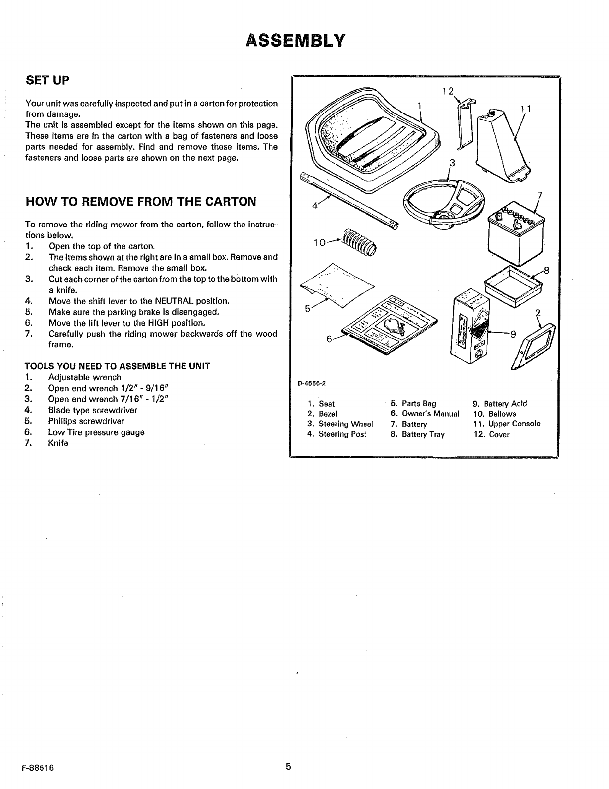
The unit is assembled except for the items shown on this page.
These items are in the carton with a bag of fasteners and loose
parts needed for assembly. Find and remove these items, The
fasteners and roose parts are shown on the next page.
HOW TO REMOVE FROM THE CARTON
To remove the riding mower from the carton, follow the instruc-
tions below.
I. Open the top of the carton,
2. The items shown at the right are in a small box. Remove and
check each item. Remove the small box.
3. Cut each corner of the carton from the top to the bottom with
a knife.
4. Move the shift lever to the NEUTRAL position.
5. Make sure the parking brake is disengaged,
6. Move the lift lever to the HIGH position,
7. Carefully push the riding mower backwards off the wood
frame,
12
11
TOOLS YOU NEED TO ASSEMBLE THE UNIT
I. Adjustable wrench
2. Open end wrench 1/2" - 9/16"
3. Open end wrench 7/16"- 1/2"
4, Blade type screwdriver
5, Phillips screwdriver
6. Low Tire pressure gauge
7. Knife
D-4656-2
I. Seat " 5. Parts Bag 9. Battery Acid
2. Bezel 6. Owner's Manual 10. Bellows
3, Steering VVhee| 7. Battery 11. Upper Console
4. Steering Post 8, Battery Tray 12. Cover
F-88516 5
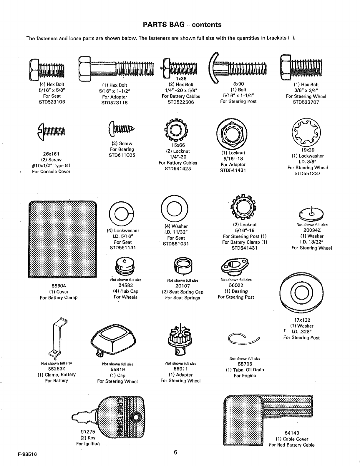
PARTS BAG - contents
The fasteners and loose parts are shown beiow. The fasteners are shown full size with the quantities in brackets ().
(4) Hex Bolt
5/16" x 5/8"
For Seat
STD523106
26x161
(2) Screw
#10xl/2" Type BT
For Console Cover
(1) Hex Bolt 6x90 (I) Hex Bolt
5/16" x 1-1/2" (1) Bolt 3/8" x 3/4"
For Adapter 5/16" x 1-1/4" For Steering Wheel
STD5231 t5 For Steering Post STD523707
(2) Hex Bolt
1/4" -20 x 5/8"
For Battery Cables
STD522506
@
(2) Screw 15x66
For Bearing (2) Locknut (1) Locknut
STD611005 I/4"-20 5/16"- 18
For Battery Cables For Adapter
STD541425 STD541431
(4) Washer (2) Locknut Notsi_OwnfutIsize
(4) Lockwasher I,D. 1!/3Z _ 5/16"-18 20094Z
I,D, 5116" For Seat For Steering Post (1) (1) Washer
For Seat STD551031 For Batter/Clamp (1) I.D. 13/32"
STD551131 STD54I 431 For Steering Wheel
19x39
(1) Lockwasher
I.D.3/8"
For Steering Wheel
STD551237
F-88516
55804
(1) Cover
ForBattery Clamp
Not shown fuilsize
55253Z
(1} Clamp, Battery
For Battery
91275
(2) Key
For Ignition
Not shown full size Not shown fullsize Not shown ful! size
24582 20107 56022
(4) Hub Cap (2) Seat Spring Cap (1) Bearing
For Wheels For Seat Springs For Steering Post "
t 7xl 32
(t) Washer
I,D, .328"
For Steering Post
Not shown full size
Not shown futl size Not shown full size 55705
55919 55911 (1) Tube, Oll Drain
(I) Cap (I} Adapter For Engine
For Steering Wheel For Steering WheeI
54148
(t) Cable Cover
For Red Battery Cable
ASSEMBLY
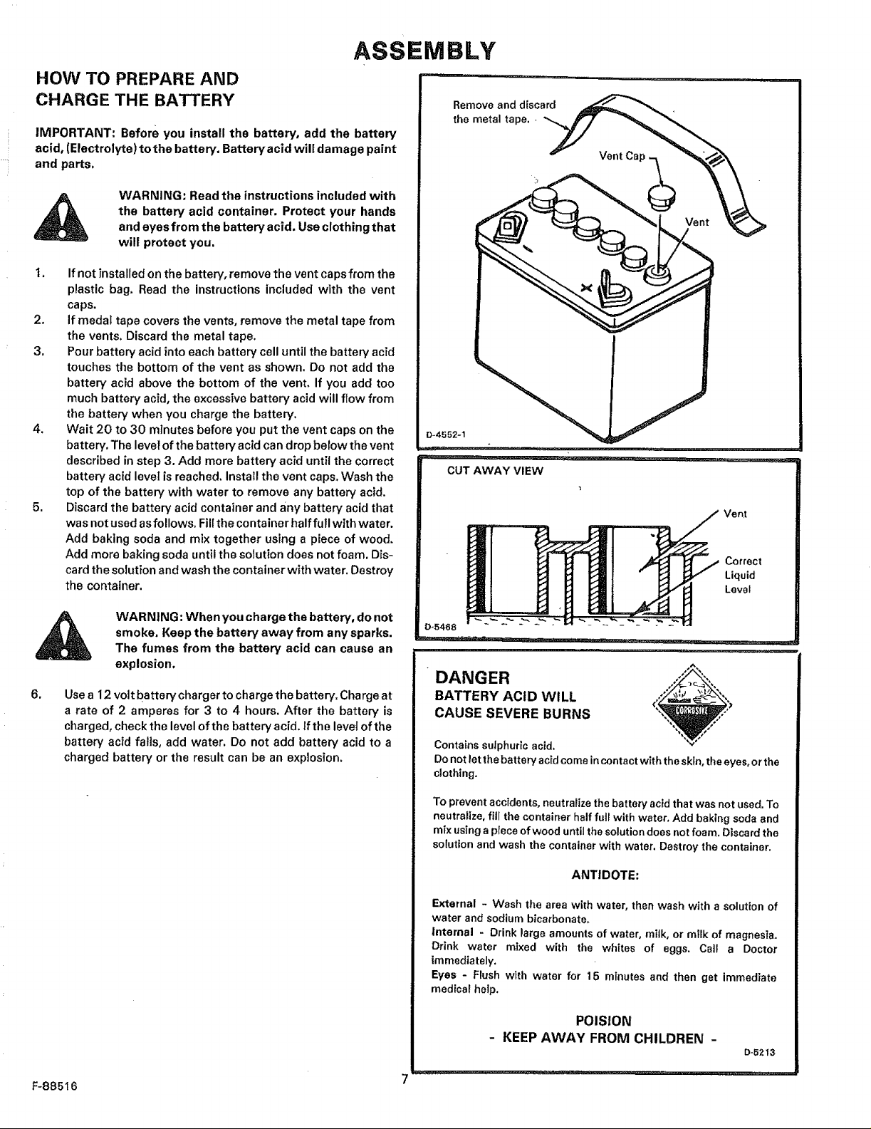
HOW TO PREPARE AND
CHARGE THE BATTERY
IMPORTANT: Before you install the battery, add the battery
acid, (Electrolyte) to the battery, Battery acid wilt damage paint
and parts,
WARNING: Read the instructions included with
the battery acid container, Protect your hands
and eyes from the battery acid. Use clothing that
will protect you,
I. Ifnot Tnstalledon the battery, removethe vent capsfrom the
plastic bag, Read the instructions included with the vent
caps,
2. If medal tape covers the vents, remove the metal tape from
the vents. Discard the metal tape.
3. Pour battery acid into each battery cell until the battery acid
touches the bottom of the vent as shown. Do not add the
battery acid above the bottom of the vent. If you add too
much battery acid, the excessive battery acid will flow from
the battery when you charge the battery.
4. Wait 20 to 30 mTnutesbefore you put the vent caps on the
battery. The level ofthe battery acid can drop below the vent
described in step 3. Add more battery acid until the correct
battery acid level is reached, Install the vent caps, Wash the
top of the battery with water to remove any battery acid,
5. Discard the battery acid container and any battery acid that
was not used asfollows. Fillthe container halffull with water.
Add baking soda and mix together using a piece of wood,
Add more baking soda until the solution does not foam, Dis-
cardthe solution and wash the container with water. Destroy
the container.
Remove and discard
the metal tape, ,
Ve n]
Correct
Liquid
Level
WARNING: Whenyou charge the battery, do not
smoke. Keep the battery away from any sparks,
The fumes from the battery acid can cause an
explosion.
6,
Use a 12 volt battery charger to charge the battery. Charge at
a rate of 2 amperes for 3 to 4 hours, After the battery is
charged, check the level ofthe battery acid. If the level of the
battery acid falls, add water. Do not add battery acid to a
charged battery or the result can be an explosion.
0-5468
DANGER _.,_,./,°"",,,,,,,
BATTERY ACID WILL "Z'=_,_____-
.... i'r,
A
<!° ",_
CAUSE SEVERE BURNS V" °'°
Containssufphuricacid.
Donotletthebatteryacidcomeincontactwith theskin,theeyes,orthe
clothing,
To prevent accidents, neutralize the battery acid that was not used. To
neutralize, fill the container half futl with water, Add baking soda and
mix using a piece of wood until the solution does not foam, Discard the
solution and wash the container with water. Destroy the container.
ANTIDOTE:
External - Wash the area with water, then wash with a solution of
water and sodium bicarbonate,
Internal - Drink large amounts of water, milk, or milk of magnesia,
Drink water mixed with the whites of eggs. Call a Doctor
immediately.
Eyes - Flush with water for 15 minutes and then get immediate
medical help.
POIStON
KEEP AWAY FROM CHILDREN -
D-5213
F-88516 7
ASSEMBLY
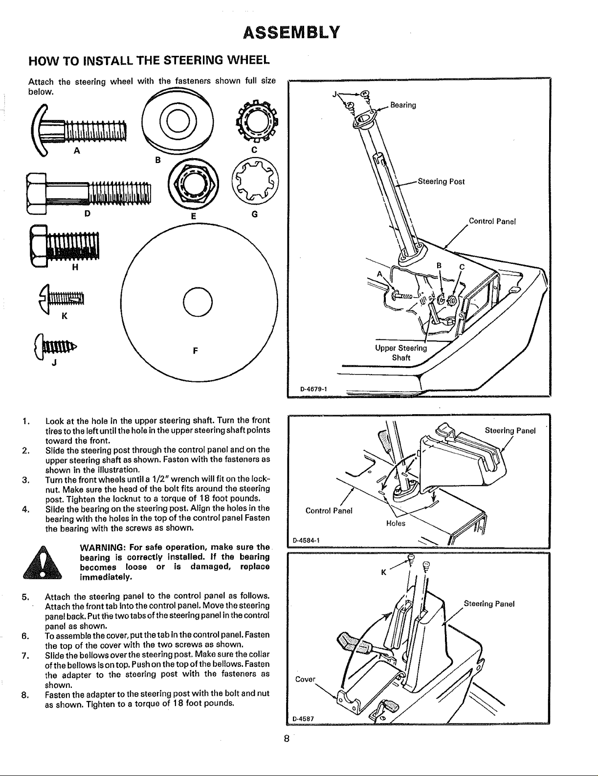
HOW TO INSTALL THE STEERING WHEEL
Attach the steering wheel with the fasteners shown full size
below.
Bearing
g Post
Control Panel
1. Lookat the hole in the upper steering shaft. Turn the front
tiresto the left untilthe hole inthe upper steering shaft points
toward the front.
2. Slide the steering postthrough the control panel and onthe
upper steering shaft as shown. Fasten with the fasteners as
shown in the illustration.
3. Turnthe front wheels until a 1/2" wrench will fit onthe lock-
nut. Make sure the head of the bolt fits around the steering
post. Tighten the Iocknut to a torque of 18 foot pounds.
4. Slide the bearing on the steering post. Align the holesin the
bearing with the holes in the top of the control panel Fasten
the bearing with the screws as shown.
Control Panel
D-4584-t
A
Upper Steering
Shaft
,, IIIH
B C
bearing is correctly installed, if the bearing
becomes loose or is damaged, replace
WARNING: For safe operation, make sure the
immediately.
5. Attach the steering panel to the control panel as follows.
Attach the front tab intothe control panel. Move the steering
panelback.Put the two tabsofthe steeringpanelinthe control
panel as shown.
6. To assemble thecover, putthetab inthe control panel.Fasten
the top of the cover with the two screws as shown.
7. Slide the bellows over the steering post. Make sure the collar
ofthe bellows isontop. Push on the top of the bellows.Fasten
the adapter to the steering post with the fasteners as
shown.
8. Fastenthe adapter to the steering post with the bolt and nut
as shown. Tighten to a torque of 18 foot pounds.
Steering Panel
•
ASSEMBLY
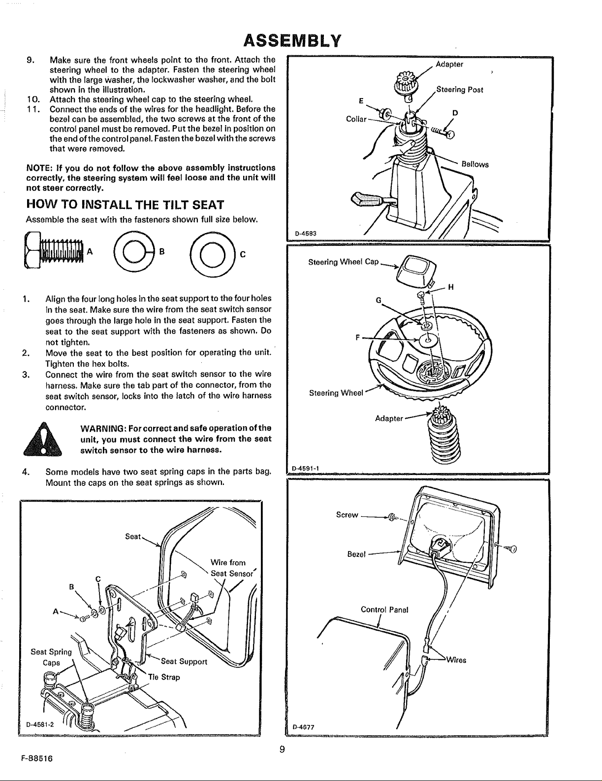
9, Make sure the front wheels point to the front. Attach the
steering wheel to the adapter. Fasten the steering wheel
with the large Washer, the lockwasher washer, and the bolt
shown in the illustration.
10. Attach the steering wheel cap to the steering wheel.
11. Connect the ends of the wires for the headlight. Before the
bezel can be assembled, the two screws at the front of the
control panel must be removed. Put the bezel in position on
the end of the control panel.Fasten the bezel with the screws
that were removed,
NOTE: if you do not follow the above assembly instructions
correctly, the steering system will feel loose and the unit will
not steer correctly.
HOW TO INSTALL THE TILT SEAT
Assemble the seat with the fasteners shown full size below.
I. Align the four long holes inthe seat support to the four holes
in the seat. Make sure the wire from the seat switch sensor
goes through the large hole in the seat support, Fasten the
seat to the seat support with the fasteners as shown, Do
not tighten.
2. Move the seat to the best position for operating the unit.
Tighten the hex bolts.
3, Connect the wire from the seat switch sensor to the wire
harness. Make sure the tab part of the connector, from the
seat switch sensor, locks into the latch of the wire harness
connector,
Adapter
Post
D
D-4583
SteeringWheel Cap=.....__
Steering _'¢heel
WARNING: For correct and safe operation of the
unit, you must connect the wire from the seat
switch sensor to the wire harness.
4. Some models have two seat spring caps in the parts bag,
Mount the caps on the seat springs as shown.
Wire from
c
Seat Spring
Cape
Strap
Sensor"
D-4591-1
Bezel
Control Panel
F-88516
D-4677
9
ASSEMBLY
CHECK THE TIRES
Check the airpressureinthe tires. Tires with too much air pressure
wilt cause the unit to ride rough,Also, the wrong air pressurewill
keep the mower housing from cutting level. The correct air
pressureisshown on the side of the tires. If the air pressure_ not
shown, inflate the tires from 10 to 12 PS1 (0,7 to 0.85 kg!_m2).
HOW TO CHECK THE MOWER HOUSING
Make surethe levelofcutset at the factory isstillcorrect. After you
mow a short distance, look at the area that was cut, If the mower
housing does not cut level, see the instructionson "How To Level
The Mower Housing" in the maintenancesection of this instruction
book.
HOW TO ATTACH THE HUB CAPS
Push each hub cap onto the center hub of each wheel. Make sure
the washer holds the hub cap in place.
FINAL ASSEMBLY
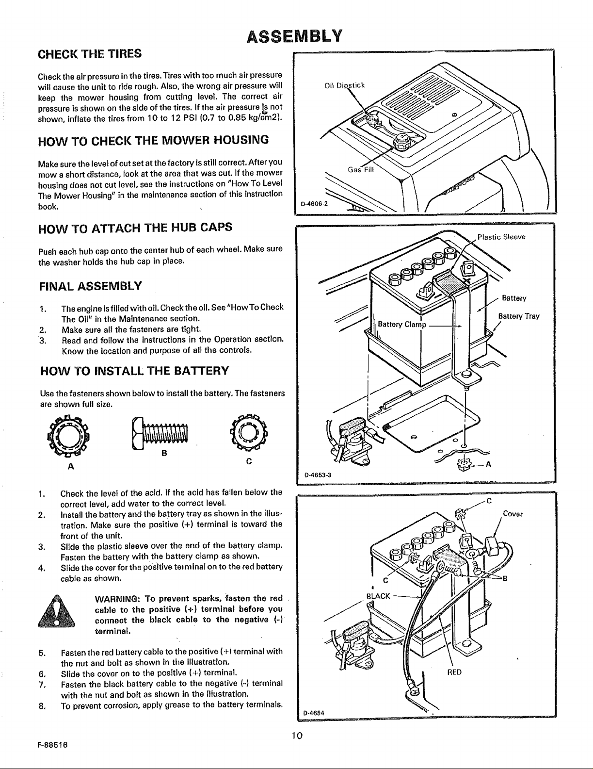
1. The engine isfilled with oil. Check the oil. See"HowTo Check
The Ot(" in the Maintenance sectton.
2. Make sure alI the fasteners are tight.
'3. Read and follow the instructions in the Operation section.
Know the location and purpose of all the controls.
0-4606-2
Plastic Sleeve
Battery
BatteryTray
/
HOW TO INSTALL THE BA'r-rERY
Usethe fasteners shown below to installthe battery. The fasteners
are shown full size.
A C
1. Check the level of the acid. If the acid has fallen below the
correct level, add water to the correct level.
2. Install the battery and the battery tray as shown in the illus-
tration. Make sure the positive (+) terminal is toward the
front of the unit.
3. Slide the plastic sleeve over the end of the battery clamp.
Fasten the battery withthe battery clamp as shown.
4. Slide the cover for the positive term inaI on to the red battery
cable as shown.
WARNING: To prevent sparks, {asten the red •
A
5. Fasten the red battery cable to the positive (+) terminal with
the nut and bolt as shown in the illustration.
6. Slide the cover on to the positive (+) terminal.
7o Fasten the black battery cable to the negative (-) terminal
with the nut and bolt as shown in the illustration.
8. To prevent corrosion, apply grease to the battery terminals.
cable to the positive (+) terminal before you
connect the black cable to the negative (-)
terminal.
0-4653-3
Cover
C
BLACK
RED
F-885t 6
10
Clutch/Brake
Pedal
OPERATION
_4757
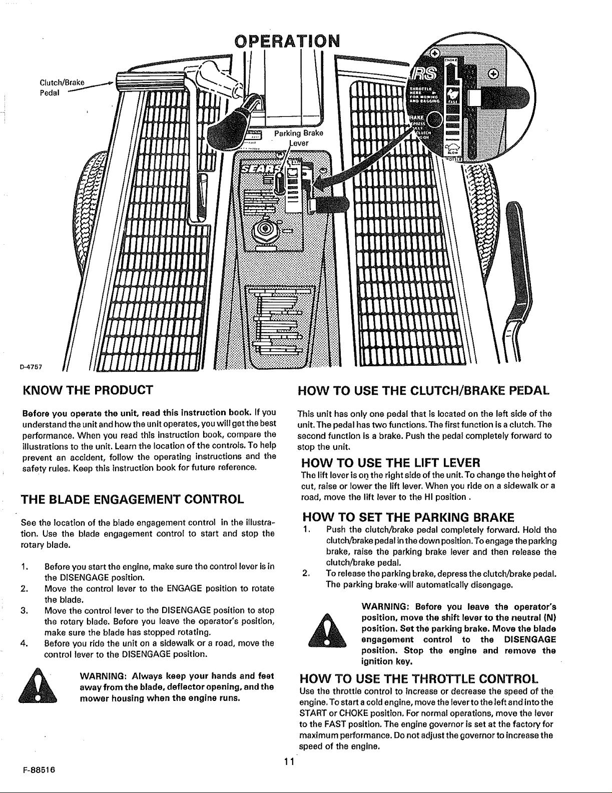
KNOW THE PRODUCT
Before you operate the unit, read this instruction book. If you
understand the unit and how the unit operates, youwill get thebest
performance, When you read this instruction book, compare the
illustrations to the unit. Learnthe location of the controls, To help
prevent an accident, follow the operating instructions and the
safety rules. Keep this instruction book for future reference.
THE BLADE ENGAGEMENT CONTROL
See the location of the btade engagement control in the illustra-
tion. Use the blade engagement control to start and stop the
rotary blade.
1. Before you start the engine, make sure the control leverisin
the DISENGAGE position.
2, Move the control lever to the ENGAGE position to rotate
the blade,
3. Move the control tever to the DISENGAGE position to step
the rotary blade. Before you leave the operator's position,
make sure the blade has stopped rotating.
4. Before you ride the unit on a sidewalk or a road, move the
control fever to the DISENGAGE position.
WARNING: Always keep your hands and feet
away from the blade, deflector opening, and the
mower housing when the engine runs.
F-88516
HOW TO USE THE CLUTCH/BRAKE PEDAL
This unit has only one pedal that is located on the left side of the
unit, The pedal hastwo functions. The first function isa clutch. The
second function is a brake. Push the pedal completely forward to
stop the unit,
HOW TO USE THE LIFT LEVER
The lift leveris on the rightside of the unit,To change the height of
cut, raise or lower the lift lever, When you ride on a sidewalk or a
road, move the lift fever to the HI position.
HOW TO SET THE PARKING BRAKE
1. Push the clutch/brake pedal completely forward. Hold the
clutclVbrakepedalin the down position.Toengagethe parking
brake, raise the parking brake lever and then release the
clutch/brake pedal.
2. To release the parking brake, depress the clutch/brake pedal.
The parking brake .will automatically disengage.
WARNING: Before you leave the operator's
position, move the shift lever to the neutral (N)
position. Set the parking brake. Move the blade
engagement control to the DISENGAGE
position. Stop the engine and remove the
ignition key.
HOW TO USE THE THROTTLE CONTROL
Use the throttle control to increase or decrease the speed of the
engine. Tostart a cold engine, move thetever tothe left and intothe
START or CHOKE position. For normal operations, move the fever
to the FAST position, The engine governoris set at the factory for
maximum performance. Do not adjust the governor to increasethe
speed of the engine.
11
OPERATION
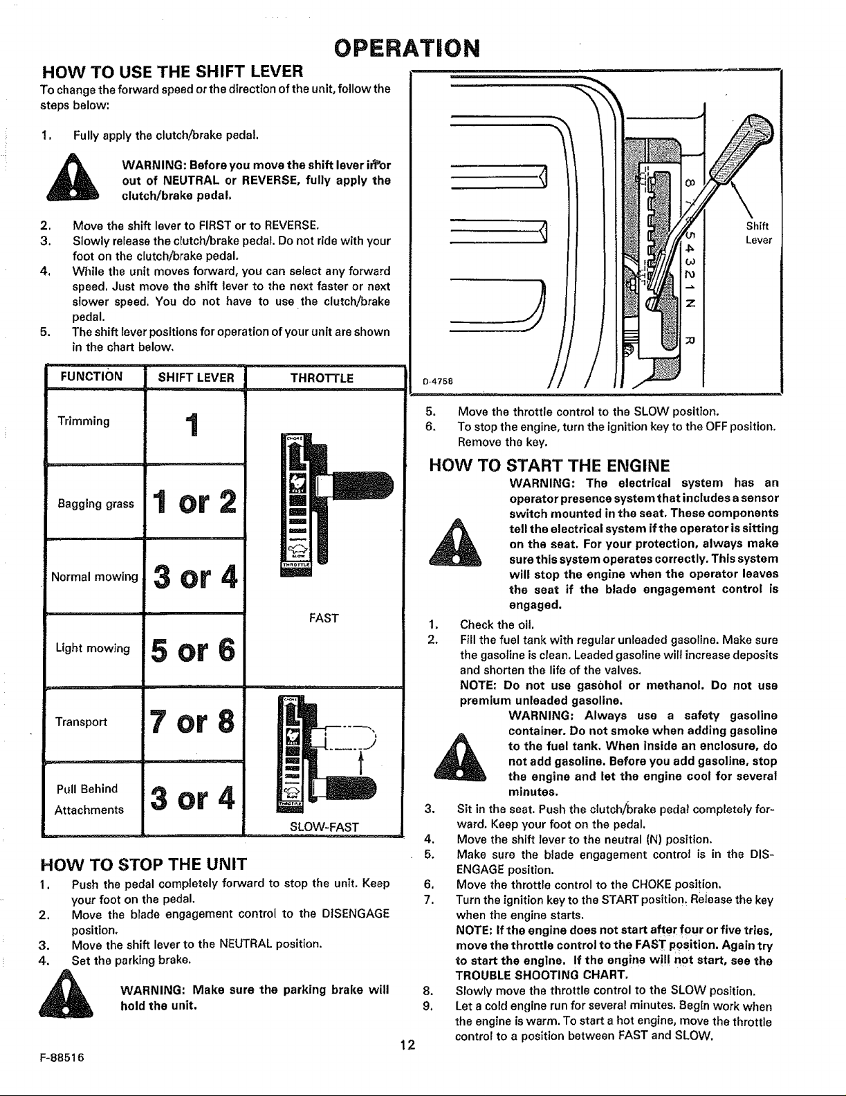
HOW TO USE THE SHIFT LEVER
To change the forward speed or the direction of the unit, follow the
steps below:
t. Fully apply the clutch/brake pedal.
out of NEUTRAL or REVERSE, fully apply the
WARNING: Before you move the shift lever ir_or
clutch/brake pedal.
2,
Move the shift lever to FIRST or to REVERSE.
3.
Slowly release the clutch!brake pedal, Do not ride with your
foot on the c[utchibrake pedal,
4_
While the unit moves forward, you can select any forward
speed, Just move the shift lever to the next faster or next
slower speed. You do not have to use the clutch/brake
pedal.
5.
The shift lever positionsfor operation of your unit are shown
in the chart below.
Shift
Lever
FUNC IONj S.IFTLEVER
Trimming 1
o0 ,oolor2
Normal mowing
Light mowing
Transpo_
Pull Behind 3or4
Attachments
3or4
5or6
7or8
THROTTLE
==z
m
m
m
m
FAST
m
SLOW-FAST
HOW TO STOP THE UNIT
1. Push the pedal completely forward to stop the unit, Keep
your foot on the pedal.
2. Move the blade engagement control to the DISENGAGE
position.
3. Move the shift lever to the NEUTRAL position.
4, Set the perking brake.
WARNING: Make sure the parking brake will
hold the unit.
F-88516
5. Move the throttle control to the SLOW position.
6. To stop the engine, turn the ignition key to the OFF position.
Remove the key.
HOW TO START THE ENGINE
WARNING: The electrical system has an
operator presence system that includes a sensor
switch mounted in the seat, These components
on the seat, For your protection, always make
tell the electrical system ifthe operator is sitting
sure this system operates correctly, This system
will stop the engine when the operator leaves
the seat if the blade engagement control is
engaged,
1. Check the oil.
2. Fillthe fuel tank with regular unleaded gasoline. Make sure
the gasoline is clean. Leaded gasoline will increasedeposits
and shorten the life of the valves.
NOTE: Do not use gasbhol or methanol. Do not use
premium unleaded gasoline.
WARNING: Always use a safety gasoline
container, Do not smoke when adding gasoline
not add gasoline. Before you add gasoline, stop
to the fuel tank, When inside an enclosure, do
the engine and let the engine coot for several
minutes,
3. Sit in the seat. Push the clutch/_orake pedal completely for-
ward. Keep your foot on the pedal.
4, Move the shift lever to the neutral (N) position.
5. Make sure the blade engagement control is in the DIS-
ENGAGE position.
6. Move the throttle control to the CHOKE position.
7, Turn the ignition key to the START position. Release the key
when the engine starts.
NOTE: If the engine does not start after four or five tries,
move the throttle control to the FAST position. Again try
to start the engine, if the engine w!!! not start, see the
TROUBLE SHOOTING CHART,
8, Slowly move the throttle control to the SLOW position,
9. Let acold engine run for several minutes. Begin work when
the engine iswarm. To start ahot engine, move the throttle
12
control to a position between FAST and SLOW.
OPERATION
HOW TO OPERATE WITH
THE MOWER HOUSING
, WARNING: The deflector is a safety device. Do
not remove the deflector. The deflector forces
the discharged material toward the ground.
Always keep the deflector in the down position.
If the deflector is damaged, replace it with a
factory replacement part.
1. Start the engine.
2. Move the lift leverto a height of cut position, in high or thick
grass, cut the grass in the high position first and then lower
the lift lever to a lower position,
3. Move the throttle control to the SLOW position.
4, Move the blade engagement controlto the ENGAGE position.
5. Push the clutch/brake pedal completely forward.
6. Move the shift lever to the first speed setting.
IMPORTANT: When you mow in heavy grass or mow
with a bagger, put the shift lever in the slowest speed.
7, Slowly release the clutch/brake pedal.
8. Move the throttle controlto the FAST position, if you need to
go faster or slower, move the shift lever to another speed
setting.
HOW TO OPERATE THE UNIT ON HILLS
WARNING; Do not ride up or down slopes that
are too steep to back straight up. Never ride the
unit across a slope, See the "Slope Guide" inthe
back of this book for information on how to
check slopes.
1. Before you ride up or down a hill, move the shift lever to the
slowest speed,
2. Do not stop or change speed settings on a hill. If you must
stop, quicklypushthe clutch/brake pedalforward and set the
parking brake.
3. To start again, make sure the shift feveristhe slowest speed.
Move the throttle control to the SLOW position. Slowly
release the pedal,
4. ifyou must stop or start on a hilt, always have enough space
for the unit to roll when you release the brake and engage
the clutch.
5. Bevery careful when you change directions on a hill.To help
prevent an accident, move the throttle control to the slow
position on a slope and in a turn,
WARNING: For better control of the unit, always
select a safe speed,
MAINTENANCE
Use the following maintenance section to keep your unit in good
operating condition,
WARNING: Before you make an inspection,
adjustment (except carburetor), or repair, dis-
connect the wire from the spark plug.
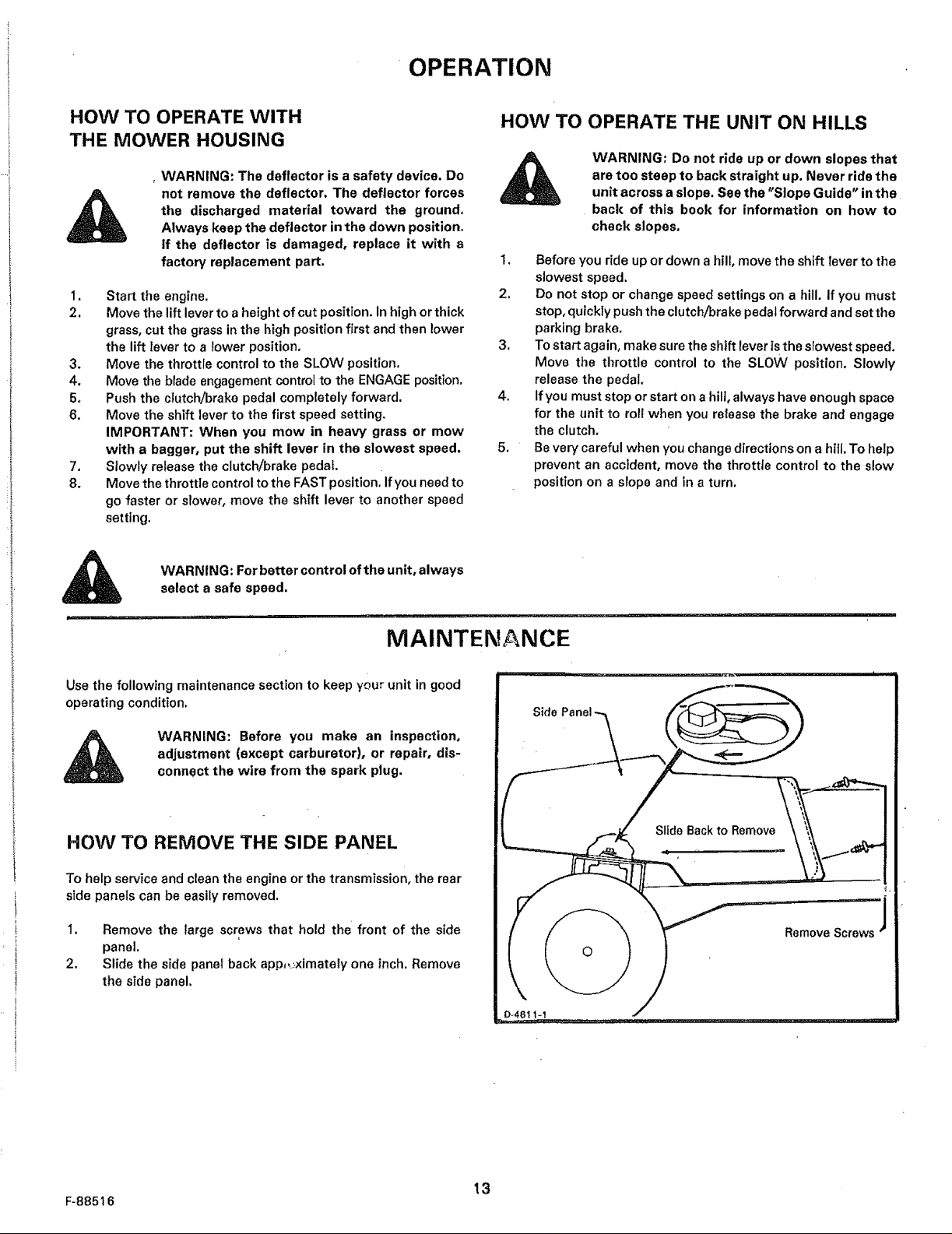
HOW TO REMOVE THE SIDE PANEL
To help service and clean the engine or the transmission, the rear
side panels can be easily removed.
t, Remove the large screws that hold the' front of the side
panel.
2. Slide the side panel back app,__.ximately one inch, Remove
the side panel,
i lilt, i,i .....
Slide Backto Remove
0
O-461 t-_
F-885t6
13
MAINTENANCE
FIRST 2 HOURS (after 2 mowings)
HOW TO CHANGE THE OIL
NOTE: Drain the oil when the engine is warm. Be careful, do not
get oil on the belts, ap
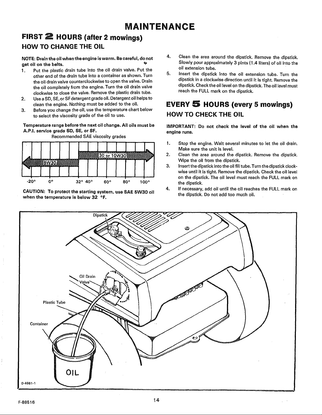
1. Put the plastic drain tube into the otI drain valve, Put the
other end of the drain tube into a container as shown. Turn
the oil drain valve counterclockwise to open the valve. Drain
the oil completely from the engine. Turn the oil drain valve
clockwise to close the valve. Remove the plastic drain tube.
2. UseaSD, SE,orSFdetergentgradeoi!.Detergentollhelpsto
clean the engine. Nothing must be added to the oil.
3, Before you change the oil, use the temperature chart below
to select the viscosity grade of the oit to use.
Temperature range before the next oil change. All oils must be
A,P,I. service grade SD, SE, or SF,
Recommended SAE viscosity grades
-20 ° 0° 32° 40 ° 60° 80° 100°
CAUTION: To protect the starting system, use SAE 5W30 oil
when the temperature is below 32 °F.
4. Clean the area around the dipstick. Remove the dipstick,
Slowly pour approximately 3 pints (1,4 liters) of oil into the
oil extension tube.
5. insert the dipstick into the oil extension tube, Turn the
dipstick in a clockwise direction until it is tight. Remove the
dipstick, Check the oil level on the dipstick. The oil level must
reach the FULL mark on the dipstick.
EVERY 5 HOURS (every 5 mowings)
HOW TO CHECK THE OIL
IMPORTANT: Do not check the level of the oil when the
engine runs.
1. Stop the engine. Wait several minutes to let the oil drain,
Make sure the unit is level,
2. Clean the area around the dipstick. Remove the dipstick,
Wipe the oil from the dipstick,
3, Insert the dipstickinto the oil fill tube, Turn the dipstick clock-
wise until it is tight. Remove the dipstick. Check the oil level
on the dipstick. The oil level must reach the FULL mark on
the dipstick.
4. tf necessary, add oil until the oil reaches the FULL mark on
the dipstick. Do not add too much oil
Plastic Tube
Container
\.,
Dipstick
OIL
F-88S_6 14
MAINTENANCE
EVERY 25 HOURS (twice a year)
HOW TO CHECK AND ADJUST
THE BLADE ENGAGEMENT CONTROL
WARNING: To prevent an injury, the blade
engagement control must operate correctly.
1. Stop the engine. Disconnect the wire from the spark plug.
2. Before you adjust the blade engagement control lever, check
and level the mower housing, See "How To Level The
Mower Housing".
3, Set the height ofthe mower housing in the lowest position.
4. Move the blade engagement control to the DISENGAGE
position.
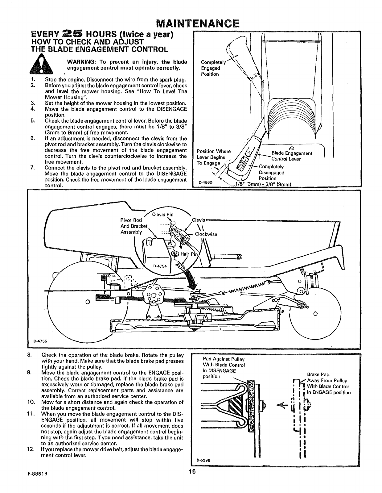
5, Check the blade engagement control lever. Before the blade
engagement control engages, there must be I/8" to 3/8"
(3mm to 9ram) of free movement.
6, If an adjustment is needed, disconnect the clevis from the
pivot rodand bracket assembly. Turn the clevis clockwiseto
decrease the free movement of the blade engagement
control. Turn the clevis counterclockwise to increase the
free movement.
7, Connect the clevis to the pivot rod and bracket assembly.
Move the blade engagement control to the DISENGAGE
position. Check the free movement of the blade engagement
control,
i i,i i1_ ii¸ i,, . ....
Position ' +;_.
L% -Oom.,o.o,y
To .
Disengaged
Position
D4s_o _1/8" (3ram)- 3/8" (9,re,m) .....
Pivot Rod
And Bracket
Assembly
O
D-4755
8, Check the operation of the blade brake. Rotate the pulley
with your hand. Make sure that the blade brake pad presses
tightly against the pulley.
9. Move the blade engagement control to the ENGAGE posi-
tion, Check the blade brake pad. If the blade brake pad is
excessively worn or damaged, replace the blade brake pad
assembly. Correct replacement parts and assistance are
available from an authorized service center,
10. Mow for a short distance and again check the operation of
the blade engagement control.
11, When you move the blade engagement control to the DIS-
ENGAGE position, all movement will stop within five
seconds if the adjustment is correct. If all movement does
not stop, again adjust the blade engagement control begin-
ning with the first step, If you need assistance, take the unit
to an authorized service center.
12. Ifyou replace the mower drive belt, adjust the blade engage-
ment control lever,
F_88516
Clevis
Clockwise
PadAgainstPulley
With BladeControl
in DfSENGAGE
D-5298
15
O
BrakePad
Away From Pulley
With Blade Control
! i i In ENGAGEposition
I
I
I
ill
I i II
HI
il
II
........ :==::___ j
MAINTENANCE
SVERV2S
BLADE SERVICE
connect the wire to the spark plug. if the blade
_[b WARNING: Before you inspect the blade, dis-
Frequently check the blade for excessive wear. cracks, or other
damage, Frequently check the nut that holds the blade. Keep the
nut tight. Ifthe blade hits an object, stop the engine, Disconnect the
wire to the spark plug. See if the blade isbent or damaged. Before
you operate the unit, replace damaged parts with factory replace-
ment parts. Every three years, have an authorized Service person
inspect the blade or replace the old blade with a factory replace-
ment blade,
Keep a sharp edge on the blade. A blade that is not sharp will cause
the ends of the grass to become brown.
hits an object, stop the engine. Disconnect the
wire to the spark plug. Check the unit for
damage,
HOURS (twice a year)
_p
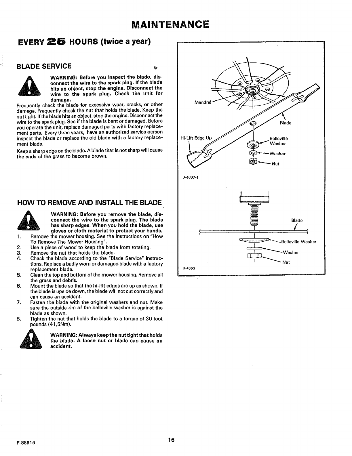
HOW TO REMOVE AND INSTALL THE BLADE
Mandrel
Blade
Hi-Lift Edge Up
D-4607-t
WARNING: Before you remove the blade, dis-
connect the wire to the spark plug. The blade
has sharp edges. When you hold the blade, use
gloves or cloth material to protect your hands.
1. Remove the mower housing. See the instructions on "How
To Remove The Mower Housing".
2. Use a piece of wood to keep the blade from rotating.
3. Remove the nut that holds the blade.
4. Check the blade according to the "Blade Service" instruc-
tions. Replacea badlyworn or damaged bladewith a factory
replacement blade,
5. Clean the top and bottom of the mower housing. Remove nil
the grass and debris.
6. Mount the blade so that the hi-lift edges are up as shown, If
the blade is upside down, the blade will not cut correctly and
can cause an accident.
7, Fasten the blade with the original washers and nut, Make
sure the outside rim of the belleville washer is against the
blade as shown,
8. Tighten the nut that holds the blade to a torque of 30 foot
pounds (41,5Nm),
WARNING: Always keep the nut tight that holds
the blade, A loose nut or blade can cause an
accident.
F-88516 16
MAINTENANCE
EVERY HOURS (twice a year)
HOW TO SHARPEN THE BLADE
WARNING: Vibration can be caused if tile blade
is not correctly balanced or if the blade is
damaged. A blade that is damaged with cracks
can break and cause an accident,
1. Sharpen the blade two times a year or every 25 hours.
2, Remove the blade according to the instructions in "HowTo
Remove The Blade",
3, Clean the blade with a brush, soap, and water. Check the
blade. Look for cracks, nicks, or other damage. If the blade is
bent, badly worn, or damaged, replace with a factory
replacement blade.
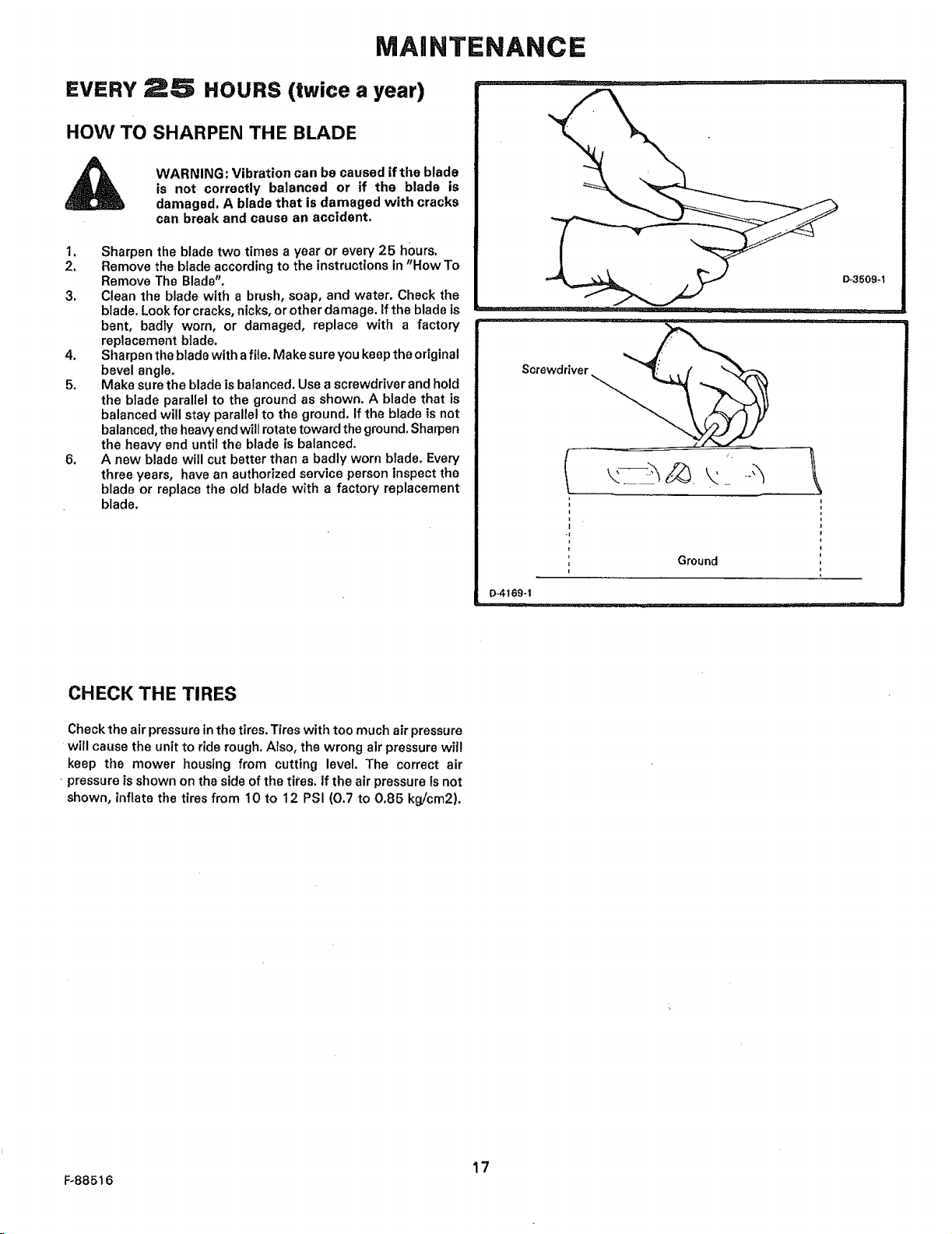
4, Sharpen the blade with afile. Make su reyou keep the original
bevel angle.
5. Make sure the blade isbalanced. Use ascrewdriver and hold
the blade parallel to the ground as shown. A blade that is
balanced will stay parallel to the ground, If the blade is not
balanced, the heavy end will rotate toward the ground.Sharpen
the heaw end until the blade is balanced,
6. A new blade will cut batter than a badly worn blade. Every
three years, have an authorized service person inspect the
blade or replace the old blade with a factory replacement
blade.
D-3509-1
CHECK THE TIRES
Check the air pressure inthe tires,Tires with too much air pressure
will cause the unitto ride rough. Also, the wrong air pressure wil!
keep the mower housing from cutting level. The correct air
• pressure isshown on the side of the tiles. If the air pressure is not
shown, inflate the tires from t0 to 12 PSI (0.7 to 0.85 kg/cm2).
O-4169-1
Ground
i
F-88516
17
 Loading...