

Craftsman 48625840, 45-0491 Owner’s Manual
A AL
odel No.
45-0491
/
50" SNOW THROWER
,, Safety
,, Assembly
,, Operation
,, Maintenance
CAUTION'.
Read Rules for
Safe Operation
and Instructions
Carefully
PRINTED IN U.S.A. FORM NO. 42432 (05/31/13)
,, Parts
Want more information or assembly tips?
Scan with free ShowUHow Mobile App
available at iTunes Store or Google Play.
ACCESSORIES...............................................................2
SAFETYRULES..............................................................3
FULLSIZEHARDWARECHART.................................4,5
CARTONCONTENTS.....................................................6
ASSEMBLY......................................................................7
OPERATION..................................................................18
MAINTENANCE............................................................19
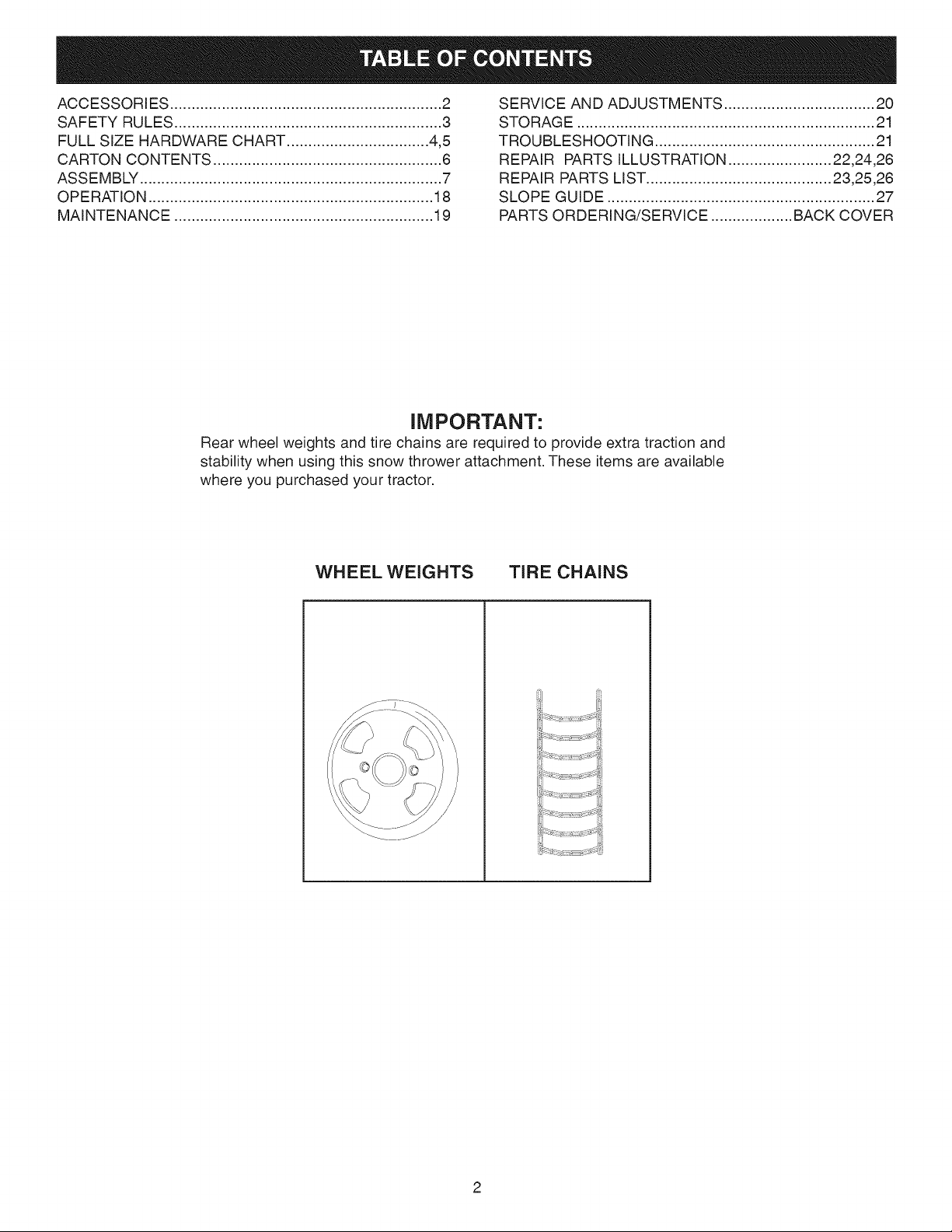
IMPORTANT:
Rear wheel weights and tire chains are required to provide extra traction and
stability when using this snow thrower attachment. These items are available
where you purchased your tractor.
SERVICEANDADJUSTMENTS...................................20
STORAGE.....................................................................21
TROUBLESHOOTING...................................................21
REPAIRPARTSILLUSTRATION........................22,24,26
REPAIRPARTSLIST...........................................23,25,26
SLOPEGUIDE..............................................................27
PARTSORDERING/SERVICE...................BACKCOVER
WHEEL WEIGHTS TIRE CHAINS
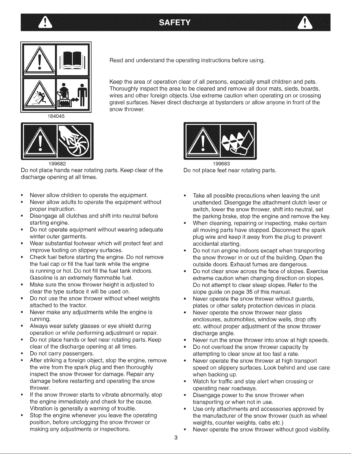
184045
Read and understand the operating instructions before using.
Keep the area of operation clear of all persons, especially small children and pets.
Thoroughly inspect the area to be cleared and remove all door mats, sleds, boards,
wires and other foreign objects. Use extreme caution when operating on or crossing
gravel surfaces. Never direct discharge at bystanders or allow anyone in front of the
snow thrower.
199682
Do not place hands near rotating parts. Keep clear of the
discharge opening at all times.
• Never allow children to operate the equipment.
Never allow adults to operate the equipment without
proper instruction.
Disengage all clutches and shift into neutral before
starting engine.
Do not operate equipment without wearing adequate
winter outer garments.
Wear substantial footwear which will protect feet and
improve footing on slippery surfaces.
Check fuel before starting the engine. Do not remove
the fuel cap or fill the fuel tank while the engine
is running or hot. Do not fill the fuel tank indoors.
Gasoline is an extremely flammable fuel.
Make sure the snow thrower height is adjusted to
clear the type surface it will be used on.
Do not use the snow thrower without wheel weights
attached to the tractor.
Never make any adjustments while the engine is
running.
Always wear safety glasses or eye shield during
operation or while performing adjustment or repair.
Do not place hands or feet near rotating parts. Keep
clear of the discharge opening at all times.
Do not carry passengers.
After striking a foreign object, stop the engine, remove
the wire from the spark plug and then thoroughly
inspect the snow thrower for damage. Repair any
damage before restarting and operating the snow
thrower.
If the snow thrower starts to vibrate abnormally, stop
the engine immediately and check for the cause.
Vibration is generally a warning of trouble.
Stop the engine whenever you leave the operating
position, before unclogging the snow thrower or
making any adjustments or inspections.
199683
Do not place feet near rotating parts.
Take all possible precautions when leaving the unit
unattended. Disengage the attachment clutch lever or
switch, lower the snow thrower, shift into neutral, set
the parking brake, stop the engine and remove the key.
When cleaning, repairing or inspecting, make certain
all moving parts have stopped. Disconnect the spark
plug wire and keep it away from the plug to prevent
accidental starting.
Do not run engine indoors except when transporting
the snow thrower in or out of the building. Open the
outside doors. Exhaust fumes are dangerous.
Do not clear snow across the face of slopes. Exercise
extreme caution when changing direction on slopes.
Do not attempt to clear steep slopes. Refer to the
slope guide on page 35 of this manual.
Never operate the snow thrower without guards,
plates or other safety protection devices in place.
Never operate the snow thrower near glass
enclosures, automobiles, window wells, drop offs
etc. without proper adjustment of the snow thrower
discharge angle.
Never run the snow thrower into snow at high speeds.
Do not overload the snow thrower capacity by
attempting to clear snow at too fast a rate.
Never operate the snow thrower at high transport
speed on slippery surfaces. Look behind and use care
when backing up.
Watch for traffic and stay alert when crossing or
operating near roadways.
Disengage power to the snow thrower when
transporting or when not in use.
Use only attachments and accessories approved by
the manufacturer of the snow thrower (such as wheel
weights, counter weights, cabs etc.)
Never operate the snow thrower without good visibility.

ATTENTION:Thehardwarebagsmaycontainsomeboltsandnutswhichdonotappearonthispageorthefollowing
page.Thoseboltsandnutswillnotbeneededfortheassemblyofyoursnowthrower.
SHOWN ACTUAL SIZE
46938
i
f
J
i
i
fA
i B
j J
/
J
J
J
J
/
i
J
43182
43063
C
.D
47630
43661
)
J
jG
48106
710-0890A
j_-_-q _
_- .............._,
fJ
43080
49933
43350
44326
43682
44215
R19171616
44695
Y
N
43088
S
O
43003
43081
T
Q
/
43070
R19172410
U
/
V W
/
43082 47810 47572 47598
/
X
x
NOT SHOWN ACTUAL SIZE
BB
J
25780
CO
HH
LL
46959
43038
46963
Y
J
731-0851A
DD
711-0332 1643-60 23727
47788 726-0178 HA23761
47134 43055 43343
J JJ KK _J
AA
J
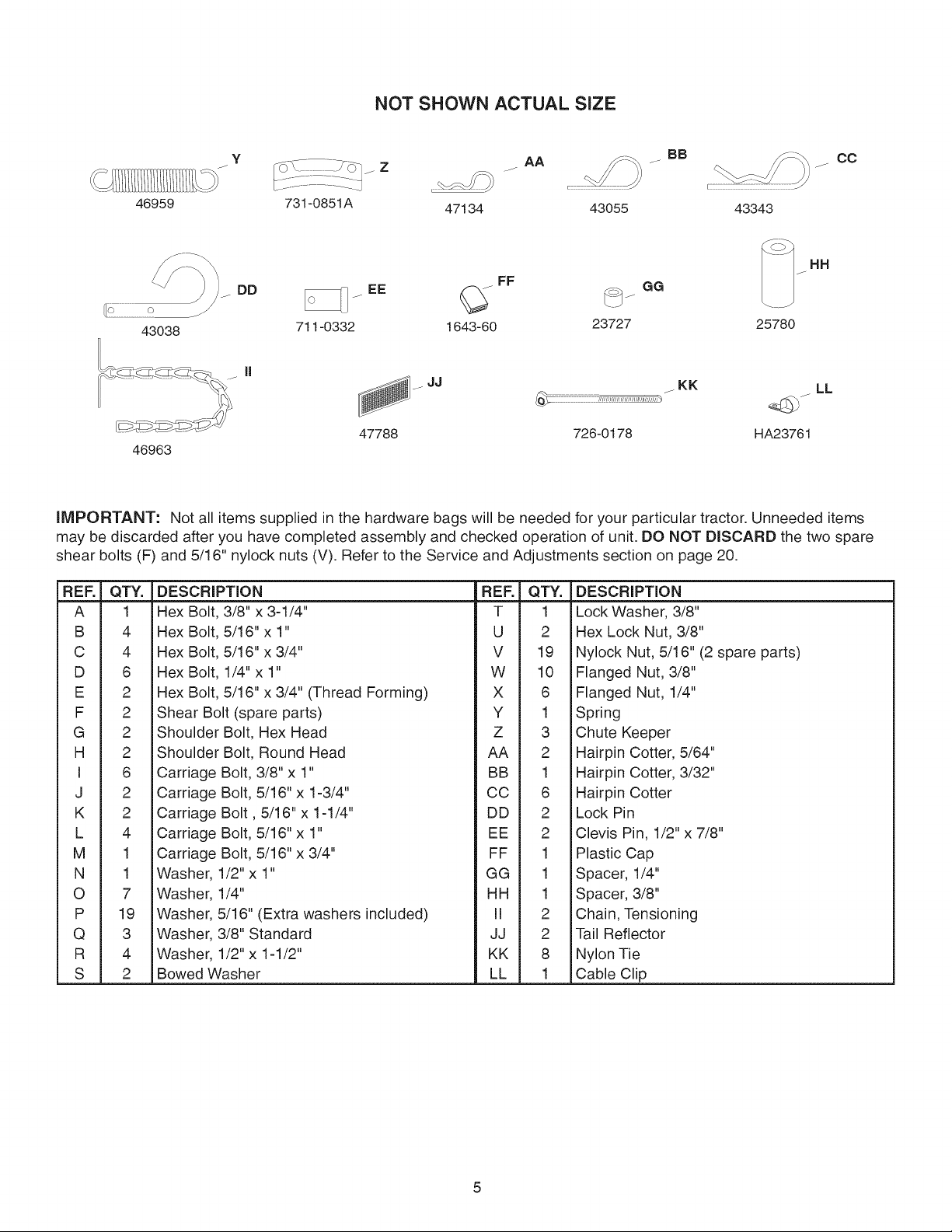
IMPORTANT: Not all items supplied in the hardware bags will be needed for your particular tractor. Unneeded items
may be discarded after you have completed assembly and checked operation of unit. DO NOT DISCARD the two spare
shear bolts (F) and 5/16" nylock nuts (V). Refer to the Service and Adjustments section on page 20.
REF. QTY. DESCRIPTION REF. QTY. DESCRIPTION
A 1 Hex Bolt, 3/8" x 3-1/4" T 1 Lock Washer, 3/8"
B 4 Hex Bolt, 5/16" x 1" U 2 Hex Lock Nut, 3/8"
C 4 Hex Bolt, 5/16" x 3/4" V 19 Nylock Nut, 5/16" (2 spare parts)
D 6 Hex Bolt, 1/4" x 1" W 10 Flanged Nut, 3/8"
E 2 Hex Bolt, 5/16" x 3/4" (Thread Forming) X 6 Flanged Nut, 1/4"
F 2 Shear Bolt (spare parts) Y 1 Spring
G 2 Shoulder Bolt, Hex Head Z 3 Chute Keeper
H 2 Shoulder Bolt, Round Head AA 2 Hairpin Cotter, 5/64"
I 6 Carriage Bolt, 3/8"x 1" BB 1 Hairpin Cotter, 3/32"
J 2 Carriage Bolt, 5/16"x 1-3/4" CC 6 Hairpin Cotter
K 2 Carriage Bolt, 5/16" x 1-1/4" DD 2 Lock Pin
L 4 Carriage Bolt, 5/16" x 1" EE 2 Clevis Pin, 1/2" x 7/8"
M 1 Carriage Bolt, 5/16" x 3/4" FF 1 Plastic Cap
N 1 Washer, 1/2"x 1" GG 1 Spacer, 1/4"
O 7 Washer, 1/4" HH 1 Spacer, 3/8"
P 19 Washer, 5/16" (Extra washers included) II 2 Chain, Tensioning
Q 3 Washer, 3/8" Standard JJ 2 Tail Reflector
R 4 Washer, 1/2" x 1-1/2" KK 8 Nylon Tie
S 2 Bowed Washer LL 1 Cable Clip
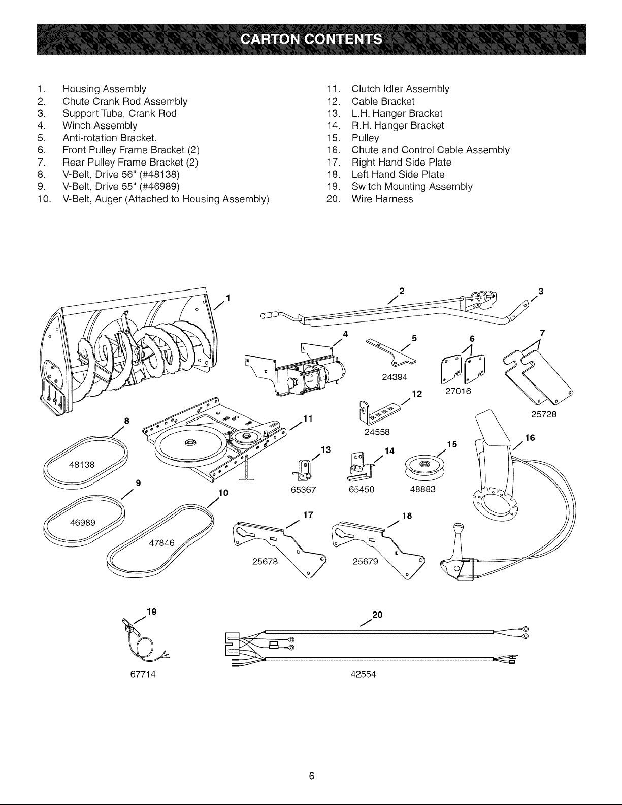
1. HousingAssembly
2. ChuteCrankRodAssembly
3. SupportTube,CrankRod
4. WinchAssembly
5. Anti-rotationBracket.
6. FrontPulleyFrameBracket(2)
7. RearPulleyFrameBracket(2)
8. V-Belt,Drive56"(#48138)
9. V-Belt,Drive55"(#46989)
10. V-Belt,Auger(AttachedtoHousingAssembly)
11. ClutchIdlerAssembly
12. CableBracket
13. L.H.HangerBracket
14. R.H.HangerBracket
15. Pulley
16. ChuteandControlCableAssembly
17. RightHandSidePlate
18. LeftHandSidePlate
19. SwitchMountingAssembly
20. WireHarness
46989
19
4 5 6
12 27016
jll 25728
24558 16
J_713 b714 _15
lO
65367 83
20
J
7
67714
42554
TOOLS REQUIRED FOR ASSEMBLY ATTACHING PARTS TO TRACTOR FRAME
(2) 7/16" Wrenches
(2) 1/2" Wrenches
(2) 9/16" Wrenches
(2) 3/4" Wrenches
(1) Screw Driver
(1) Knife
REMOVAL OF PARTS FROM CARTON
Remove all loose parts, parts bags and hardware
bags from the carton. Lay out and identify parts and
hardware using the illustrations on pages 4, 5 and 6.
IMPORTANT: Not all items supplied in the hardware
bag will be needed for your particular tractor. Unneeded
items may be discarded after you have completed
assembly and checked operation of unit. DO NOT
DISCARD the two spare shear bolts and 5/16" nylock
nuts. Refer to the Service and Adjustments section on
page 20.
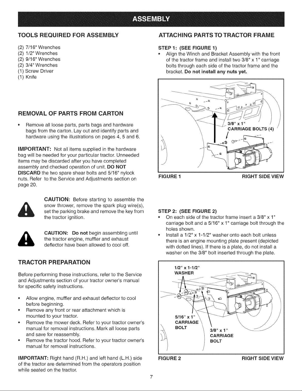
STEP 1: (SEE FIGURE 1)
• Align the Winch and Bracket Assembly with the front
of the tractor frame and install two 3/8" x 1" carriage
bolts through each side of the tractor frame and the
bracket. Do not install any nuts yet.
FIGURE 1 RIGHT SIDE VIEW
CAUTION: Before starting to assemble the
snow thrower, remove the spark plug wire(s),
set the parking brake and remove the key from
the tractor ignition.
CAUTION: Do not begin assembling until
&
the tractor engine, muffler and exhaust
deflector have been allowed to cool off.
TRACTOR PREPARATION
Before performing these instructions, refer to the Service
and Adjustments section of your tractor owner's manual
for specific safety instructions.
Allow engine, muffler and exhaust deflector to cool
before beginning.
Remove any front or rear attachment which is
mounted to your tractor.
Remove the mower deck. Refer to your tractor owner's
manual for removal instructions. Mark all loose parts
and save for reassembly.
Remove the tractor hood. Refer to your tractor owner's
manual for removal instructions.
STEP 2: (SEE FIGURE 2)
On each side of the tractor frame insert a 3/8" x 1"
carriage bolt and a 5/16" x 1" carriage bolt through the
holes shown.
Install a 1/2" x 1-1/2" washer onto each bolt unless
there is an engine mounting plate present (depicted
with dotted lines). Ifthere is a plate, do not install a
washer on the 3/8" bolt inserted through the plate.
1/2" x 1-1/2"
WASHER
5/16" x 1"
CARRIAGE
BOLT
3/8"×1"
CARRIAGE
BOLT
iMPORTANT: Right hand (R.H.) and left hand (L.H.) side
of the tractor are determined from the operators position
while seated on the tractor.
FIGURE 2 RIGHT SIDE VIEW
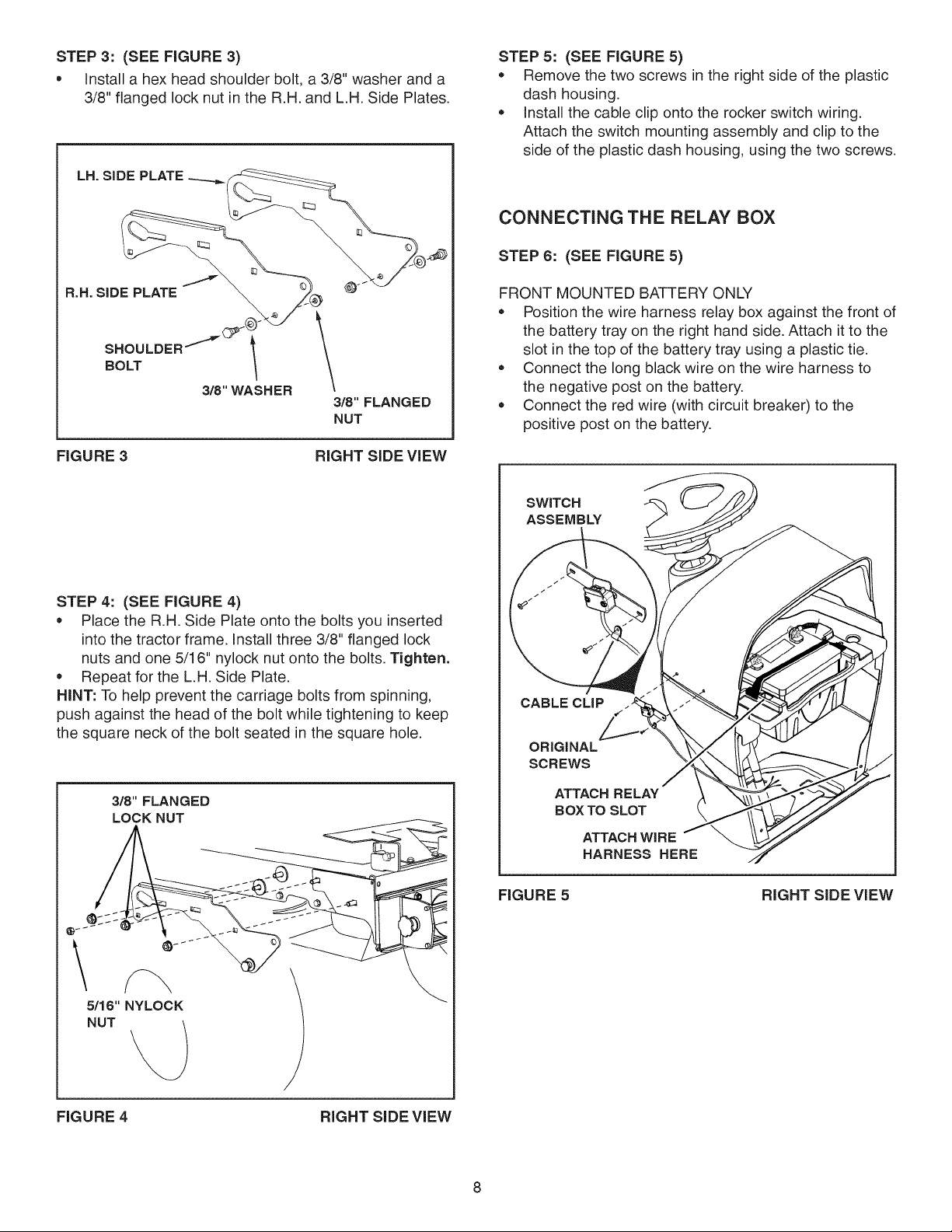
STEP3: (SEEFIGURE3)
• Installahexheadshoulderbolt,a3/8"washeranda
3/8"flangedlocknutintheR.H.andL.H.SidePlates.
LH. SiDE PLATE ---_i
STEP 5: (SEE FIGURE 5)
Remove the two screws in the right side of the plastic
dash housing.
install the cable clip onto the rocker switch wiring.
Attach the switch mounting assembly and clip to the
side of the plastic dash housing, using the two screws.
CONNECTING THE RELAY BOX
STEP 6: (SEE FIGURE 5)
R.H. SIDE PLATE @
SHOULDER_ l
BOLT
3/8"WASHER
FIGURE 3 RIGHT SiDE ViEW
3/8" FLANGED
NUT
STEP 4: (SEE FIGURE 4)
Place the R.H. Side Plate onto the bolts you inserted
into the tractor frame, install three 3/8" flanged lock
nuts and one 5/16" nylock nut onto the bolts. Tighten.
Repeat for the L.H. Side Plate.
HINT: To help prevent the carriage bolts from spinning,
push against the head of the bolt while tightening to keep
the square neck of the bolt seated in the square hole.
FRONT MOUNTED BATTERY ONLY
Position the wire harness relay box against the front of
the battery tray on the right hand side. Attach it to the
slot in the top of the battery tray using a plastic tie.
Connect the long black wire on the wire harness to
the negative post on the battery.
Connect the red wire (with circuit breaker) to the
positive post on the battery.
SWITCH
ASSEMBLY
CABLE CLiP
ORiGiNAL
SCREWS
3/8" FLANGED
LOCK NUT
5/16" NYLOCK
FIGURE 4 RIGHT SiDE ViEW
ATTACH RELAY
BOX TO SLOT
ATTACH WiRE
HARNESS HERE
FIGURE 5 RIGHT SiDE ViEW
STEP 7:
REAR MOUNTED BATTERY ONLY
• Mount the wire harness relay box in front of the
solenoid on the right hand side of the gas tank,
attaching it with a plastic tie.
• Attach the long black wire of the wire harness under
the head of the screw that fastens down the right
hand side of the gas tank.
• Attach the red wire (with circuit breaker) to the rear
solenoid terminal where the battery cable is attached.
• Connect the short red, black and green wires to the
three wires of the switch mounting assembly, joining
together like colored wires.
iNSTALLiNG THE WiRE HARNESS
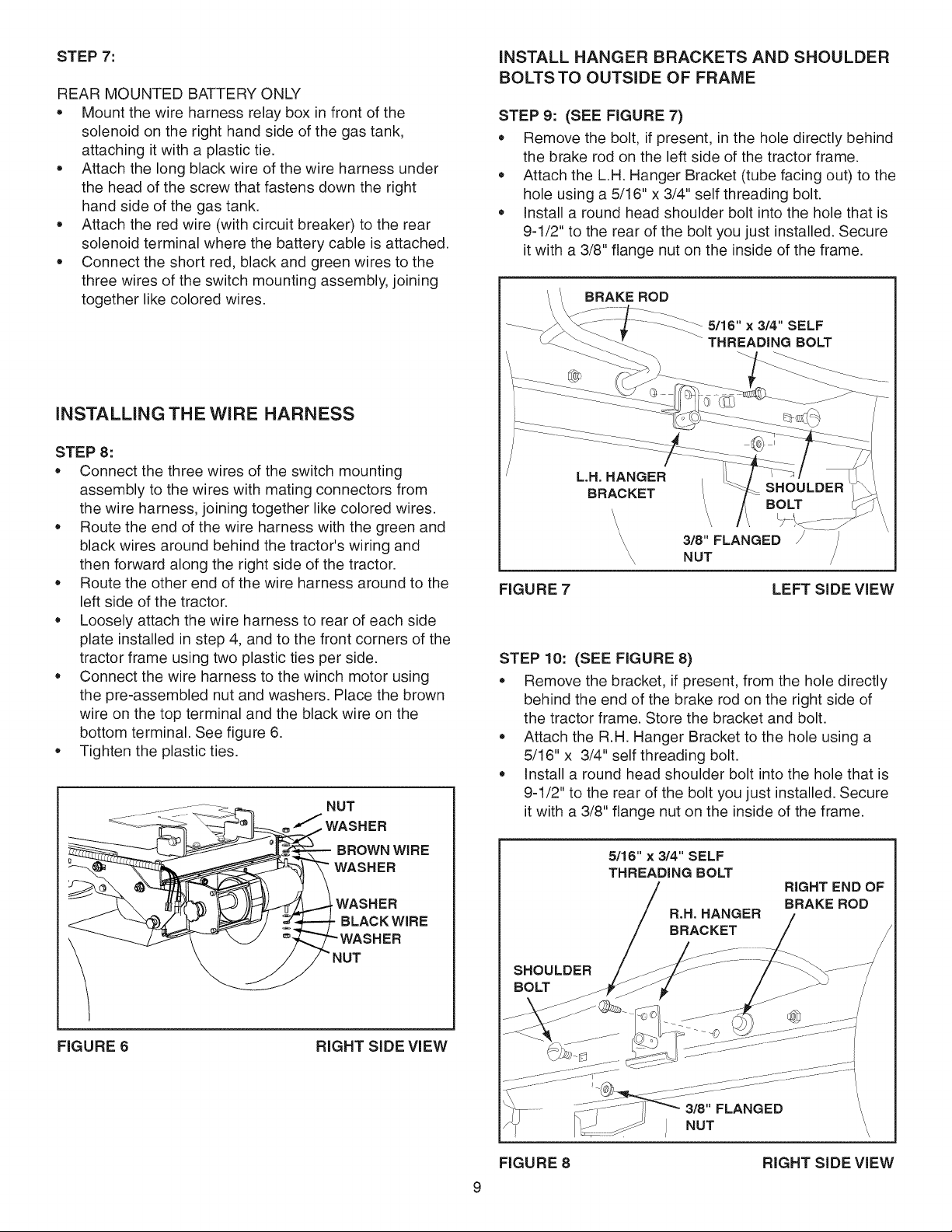
STEP 8:
• Connect the three wires of the switch mounting
assembly to the wires with mating connectors from
the wire harness, joining together like colored wires.
• Route the end of the wire harness with the green and
black wires around behind the tractor's wiring and
then forward along the right side of the tractor.
• Route the other end of the wire harness around to the
left side of the tractor.
• Loosely attach the wire harness to rear of each side
plate installed in step 4, and to the front corners of the
tractor frame using two plastic ties per side.
• Connect the wire harness to the winch motor using
the pre-assembled nut and washers. Place the brown
wire on the top terminal and the black wire on the
bottom terminal. See figure 6.
• Tighten the plastic ties.
NUT
WASHER
BROWN WiRE
WASHER
,WASHER
BLACK WiRE
INSTALL HANGER BRACKETS AND SHOULDER
BOLTSTO OUTSIDE OF FRAME
STEP 9: (SEE FIGURE 7)
• Remove the bolt, if present, in the hole directly behind
the brake rod on the left side of the tractor frame.
• Attach the L.H. Hanger Bracket (tube facing out) to the
hole using a 5/16" x 3/4" self threading bolt.
• Install a round head shoulder bolt into the hole that is
9-1/2" to the rear of the bolt you just installed. Secure
it with a 3/8" flange nut on the inside of the frame.
BRAKE ROD
5/16" x 3/4" SELF
THREADING BOLT
L.H. HANGER
BRACKET
, \
\\ \, \
\
\ 3/8" FLANGED
\
Y, NUT
FIGURE 7
LEFT SIDE VIEW
STEP 10: (SEE FIGURE 8)
• Remove the bracket, if present, from the hole directly
behind the end of the brake rod on the right side of
the tractor frame. Store the bracket and bolt.
• Attach the R.H. Hanger Bracket to the hole using a
5/16" x 3/4" self threading bolt.
• Install a round head shoulder bolt into the hole that is
9-1/2" to the rear of the bolt you just installed. Secure
it with a 3/8" flange nut on the inside of the frame.
5/16" x 3/4" SELF
THREADING BOLT
R.H. HANGER
BRACKET
RIGHT END OF
BRAKE ROD
FIGURE 6 RIGHT SIDE VIEW
SHOULDER
BOLT
FIGURE 8
\
\
RIGHT SIDE VIEW
 Loading...