

Craftsman 486254072 Owner’s Manual
owners
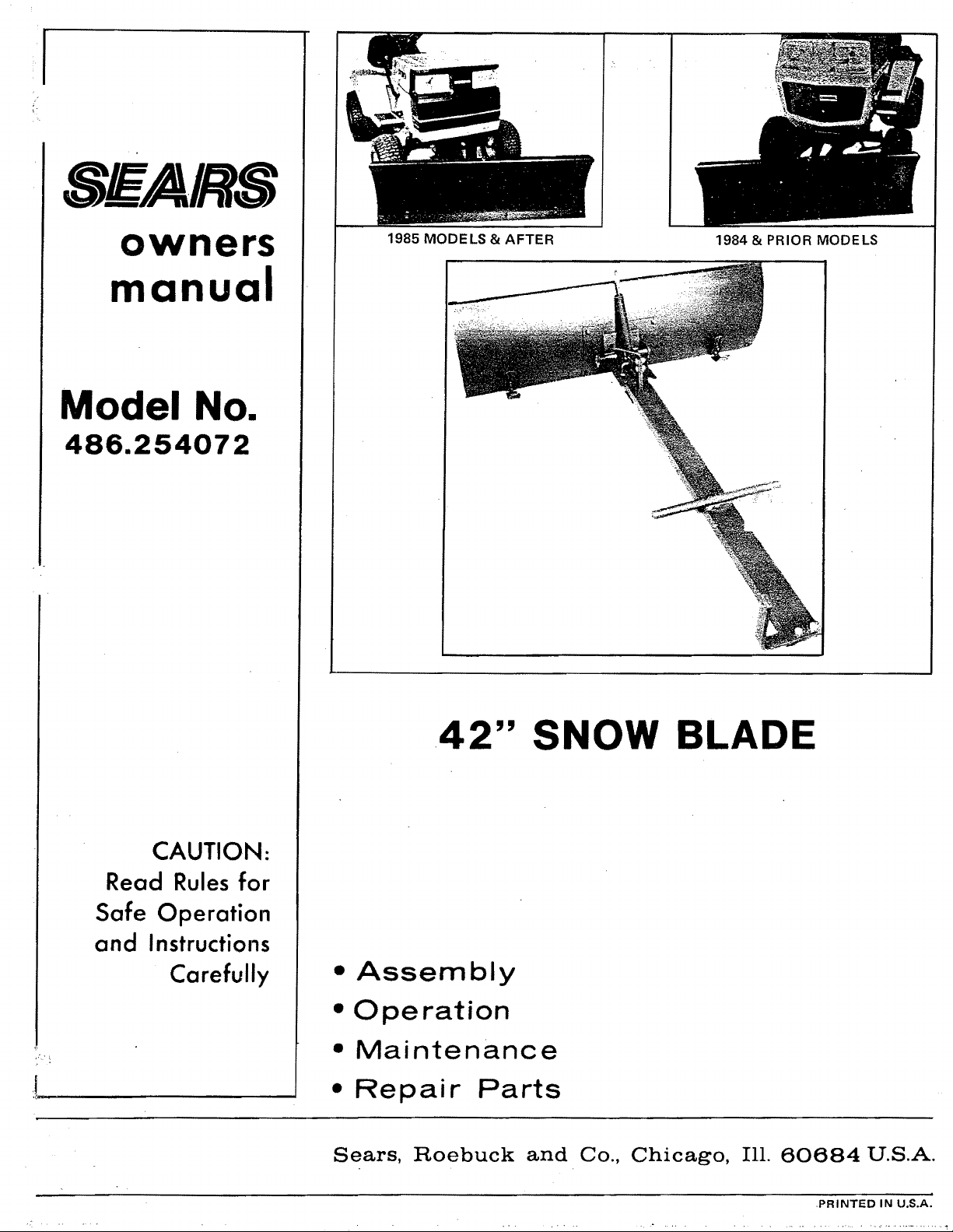
manual
Model No.
486.254072
1985 MODELS & AFTER
1984 & PRIOR MODELS
CAUTION:
Read Rules for
Safe Operation
and Instructions
Carefully
42" SNOW BLAD
• Assembly
• Operation
• Maintenance
• Repair Parts
Sears, Roebuck and Co., Chicago, Ill. 60684 U.S.A.
,( .....
.PRINTED IN U.S.A.
' RULES FOR SAFE OPERATIONS
Remember, any power equipment can cause injury if operated improperly or if the user does not understand how
to operate the equipment.
Exercise caution at all times, when using power equipment.
1. Read the Owners Manuals and know how to operate your lawn tractor, before using with the snow blade
attachment.
=
Never operate lawn tractor and snow blade without wearing proper clothing suited to weather conditions and
operation of controls.
3.
Never allow children to operate lawn tractor and snow blade, and do not allow adults to operate without proper
instructions.
4. Always begin with transmission in first (low) gear and engine at low speed, and gradually increase speed as
required.
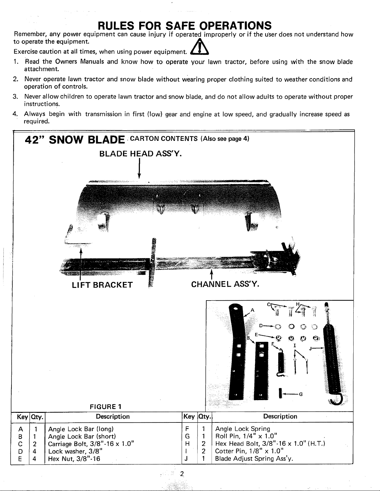
42" SNOW BLADE CARTON CONTENTS (Also see page 4)
BLADE HEAD ASS'Y.
!
Key
A
B
C
D
E
LI FT BRACKET
FIGURE 1
Qty.
1
Angle Lock Bar (long)
1
Angle Lock Bar (short)
2
Carriage Bolt, 3/8"-16 x 1.0"
4
Lock washer, 3/8"
4
Hex Nut, 3/8"-16
Description
CHANNEL ASS'Y.
A
Key
Qty. Description
F
1 Angle Lock Spring
G
1 Roll Pin, 1/4" x 1.0"
H
2 Hex Head Bolt, 3/8":16 x 1.0"
I
2 Cotter Pin, 1/8" x 1.0"
J
1 Blade Adjust Spring Ass'y.
© O ©
I
©
(H.T.)
••::: 2 ¸
ASSEMBLY INSTRUCTIONS
TOOLS REQUIRED FOR ASSEMBLY
(1) Pliers'
(1) Small Hammer
(2) 1/2" open or boxed end wrench
(2) 9/16" open or boxed end wrench
Before attempting to assemble the blade, layout the
blade head assembly, channel assembly and all other
parts, as shown in figure 1.
°
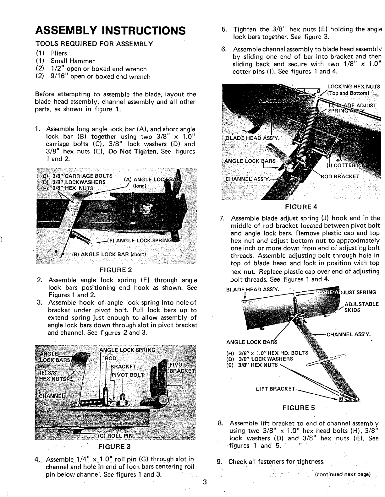
Assemble long angle lock bar (A), and short angle
lock bar (B) together using two 3/8" x 1.0"
carriage bolts (C), 3/8" lock washers (D)and
3/8" hex nuts (E), Do Not Tighten. See figures
1 and 2.
.
Tighten the 3/8" hex nuts (E) holding the angle
lock bars together..See figure 3.
.
Assemble channel assembly to blade head assembly
by sliding one end of bar into bracket and then
sliding back and secure with two 1/8" x 1.0"
cotter pins (I). See figures 1 and 4.
LOCKING HEX NUTS
) and Bottom),.: .._.
ADJUST
FIGURE 2
,
Assemble angle lock spring (F) through angle
lock bars positioning end hook as shown. See
Figures 1 and 2.
,
Assemble hook of angle lock spring into hole of
bracket under pivet bolt. Pull lock bars up to
extend spring just enough to allow assembly of
angle lock bars down through slot inpivot bracket
and channel. See figures 2 and 3.
__CHANNE L
BRACKET
FIGURE 4
.
Assemble blade adjust spring (J) hook end in the
middle of rod bracket located between pivot bolt
and angle lock bars. Remove plastic cap and top
hex nut and adjust bottom nut to approximately
one inch or more down from end of adjusting bolt
threads. Assemble adjusting bolt through hole in
top of blade head and lock in position with top
hex nut. Replace plastic cap over end of adjusting
bolt threads. See figures 1 and 4.
BLADE HEAD ASS'Y.
ADJUSTABLE
HANNEL ASS'Y.
ANGLE LOCK BARS
(H) 3/8" x 1.0" HEX HD. BOLTS
(D) 3/8" LOCK WASHERS
(E) 3/8" HEX NUTS
SPRING
LI Fr
FIGURE 5
,
Assemble lift bracket to end of channel assembly
using two 3/8" x 1.0" hex head bolts (H). 3/8"
lock washers (D) and 3/8" hex nuts (E). See
:: FIGURE3
figures 1 and 5. '
4 .....Assemble 1/4" x !.0,.'.roll.pin (G) through slot in 9. Check all fasteners for tightness; .
channel and hole in end of lock bars centering roll ...
pin below channel. Seefigures 1 and 3...... ii : " " "(continued next page)
3
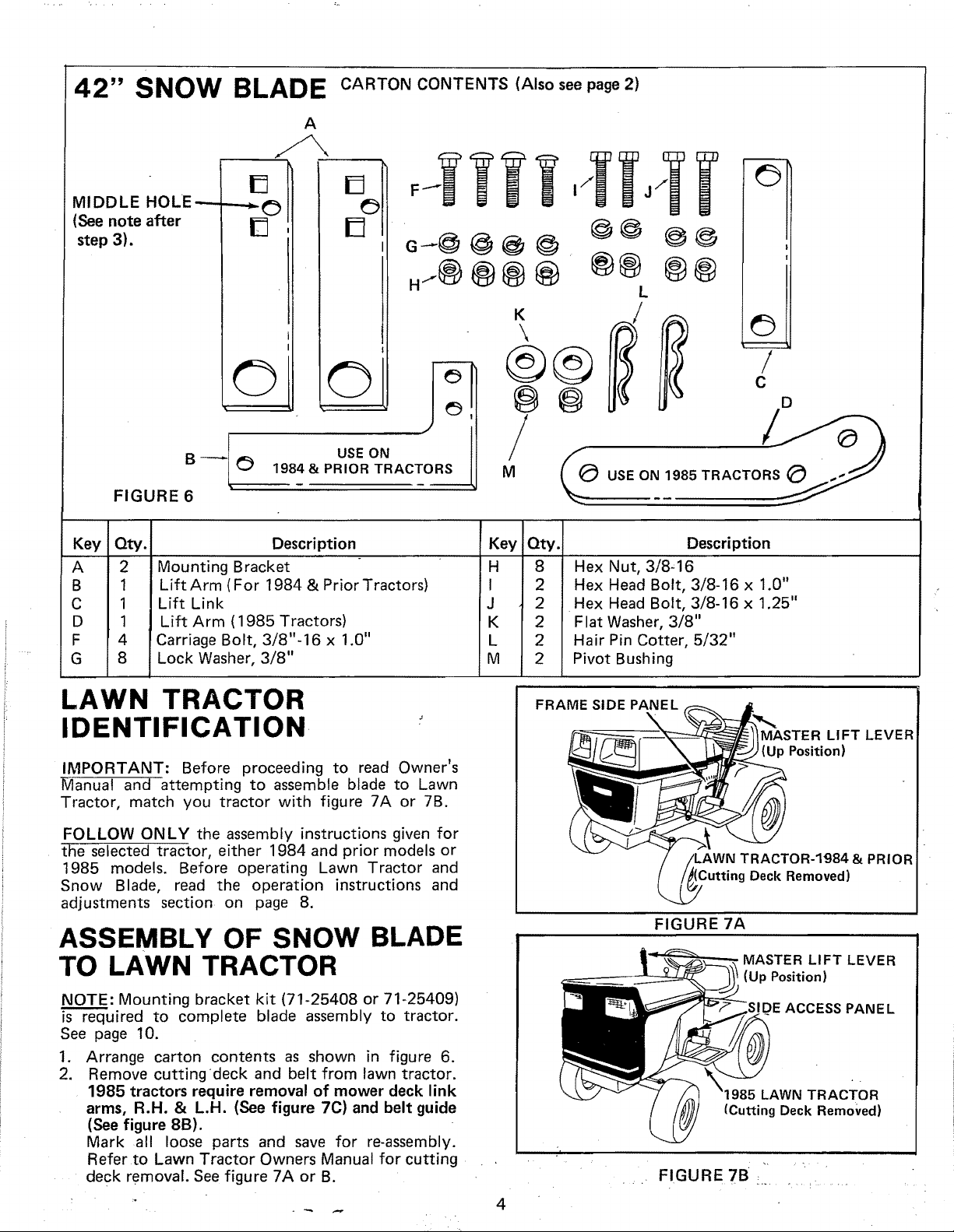
42" SNOW BLADE CARTON CONTENTS (Also see page 2)
A
MIDDLE HOLE---
(See note after
step 3).
FIGURE 6
Key Qty.
A 2
B 1
C 1
D 1
F 4
G 8
Mounting Bracket
Lift Arm ( For 1984 & Prior Tractors)
Lift Link
Lift Arm ( 1985 Tractors)
Carriage Bolt, 3/8"-16 x 1.0"
Lock Washer, 3/8"
[]
r_
%
[]
F ! 7 j7 _)
1
N ®@
L
K
/
\
D
©@
©
g
1984 & PRIOR TRACTORS i
Description
©
USEON i
Key
H
I
J
K
L
M
/
M
Qty.
8
2
2
2
2
2
Hex Nut, 3/8-16
Hex Head Bolt, 3/8-16 x 1.0"
Hex Head Bolt, 3/8-16 x 1.25"
Flat Washer, 3/8"
Hair Pin Cotter, 5/32"
Pivot Bushing
Description
i
_m
/
C
D@@
TRACTO__
LAWN TRACTOR
IDENTIFICATION.
IMPORTANT: Before proceeding to read Owner's
Manual and attempting to assemble blade to Lawn
Tractor, match you tractor with figure 7A or 7B.
FOLLOW ONLY the assembly instructions given for
the selected tractor, either 1984 and prior models or
1985 models. Before operating Lawn Tractor and
Snow Blade, read the operation instructions and
adjustments section on page 8.
ASSEMBLY OF SNOW BLADE
TO LAWN TRACTOR
NOTE: Mounting bracket kit (71-25408 or 71-25409)
is required to complete blade assembly to tractor.
See page 10.
1. Arrange carton contents as shown in figure 6.
2. Remove cutting deck and belt from lawn tractor.
1985 tractors require removal of mower deck link
arms, R.H. & L.H. (See figure 7C) and belt guide
(See figure 8B).
Mark all loose parts and save for re-assembly.
Refer to Lawn Tractor Owners Manual for cutting
deck removal. See figure 7A or B.
FRAME SIDE PANEL
4
MASTER LIFT LEVER
Position)
TRACTOR-1984 & PRIOR
(Cutting Deck Removed)
FIGURE 7A
MASTER LIFT LEVER
(Up Position)
SIDE ACCESS PANEL
LAWN TRACTOR
(Cutting Deck Removed)
I" I JP_ I I I'_ r --yrt
r,_un= _o ........ ......
 Loading...