

Page 1
SEARS
OWNER'S
MANUAL
MODEL NO.
390.251483
390.251883
CAUTION:
Read and Follow
All Safety Rules and
Operating Instructions
Before First Use of
This Product.
Save This Manual For
Future Reference.
Sears, Roebuck and Co., Hoffman Estates, IL 60179 U.S.A.
PRINTED IN U.S.A.
CRflFTSMflN^
PROFESSIONAL
“HYDROGLASS”®
SHALLOW WELL JET PUMP
• Safety Instructions
• Installation
• Operation
• Troubleshooting
• Repair Parts
Form No. F642-9906 (Rev, 4/18/01)
Page 2

READ AND FOLLOW SAFETY INSTRUCTIONS!
This is the safety alert symbol. When you see this symbol on your
pump or in this manual, look for one of the following signal words
A
A DANGER
A WARNING
A CAUTION
and be alert to the potential for personal injury:
DANGER warns about hazards that will cause serious personal
injury, death or major property damage if ignored.
WARNING warns about hazards that will or can cause serious
personal injury, death or major property dam^e if ignored.
CAimON warns about hazards that will or can cause minor per
sonal injury or property damage if ignored. .
The label NOTICE indicates special instructions which are im
portant but not related to hazards.
Carefully read and follow all safety instructions in this
manual and on pump.
Keep safety labels in good condition.
Replace missing or damaged safety labels.
Relief valve must be capable of passing full pump flow at 75 PSI.
Pump water only with this pump.
Electrical Safety
Wire motor for correct
A
A WARNING
Hazardous voltage.
Can shock, burn, or
cause death.
Ground pump before
connecting to power
supply.
Make workshopj childproof; use padlocks and master switches;
remove starter keys.
voltage. See “Electrical”
section of this manual
and motor nameplate.
Ground motor before
connecting to power
supply.
Meet National Elect
rical Code and local
codes for all wiring.
^ Follow wiring instruc
tions in this manual
when connecting mo
tor to power lines.
General Safety
Do not allow pump, pres,sure tank, piping, or any other system
component containing water to freeze. Freezing may damage sys
tem, leading to injuiy' or flooding. Allowing pump or system com
ponents to freeze will void warranty.
General Safety
A WARNING
Hazardous pressure!
Install pressure relief
valve in discharge pipe.
Release all pressure on
system before working on
any component.
Periodically inspect pump and system components.
Wear safety glasses at all times when working on pumps.
Keep work area clean, uncluttered and properly lighted; store
properly all unused tools and equipment.
Keep visitors at a safe distance from the work areas.
A WARNING pujnp body may explode if used as a booster
pump unless reUef valve capable of passing full pump flow
at 75 PSI (517 kPa) is installed.
A CAUTION j^jotor normally operates at high temperature and
will be too hot to touch. It is protected from heat damage during
operation by an automatic internal cutoff switch. Before handling
pump or motor, stop motor and allow it to cool for 20 minutes.
Model
No.
390.251483
390.251883
TABLE I - Pump Performance (in Gallons per Minute)
Pumping Depth in Feet
5’ 10’ 15’
8.2
10.9 10.4 8.6
Description
1/2 HP S.W. Jet
3/4 HP S.W. Jet
Suet.
1-1/4"
1-1/4”
Disch.
1 ”
1"
Discharge
Pressure PSI
40
40
7.3
6.2
20’
5,0
7.5
Page 3
CONTENTS
Safety.......................................................................................................... 2
W ananty/Introduction.............................................................................3
Pump Performance................................................................................... 3
Major Components............................................................................... 3-4
Piping..........................................................................................................4
Electrical..................................................................................................... 5
Installation..................................................................................................6
Operation....................................................................................................6
Maintenance............................................................................................7-8
Helpful Hints.............................................................................................8
Troubleshooting Guide...........................................................................-P
Repair Parts........................................................................................10-11
INTRODUCTION
We suggest you take a few minutes to read the instructions con
tained in this manual before installing and using your pump. This
will help you obtain the full benefits of the quality and convenience
built into this equipment. It will also help you avoid any needless
service expense resulting from causes beyond our control which
naturally cannot be covered in our warranty.
^twic tWs piiiiv>,':tree o£(
'.pitopess
CRAFTS
'' Aftjr wie. will fhrhte^- ft«*?
Hits waitantr dots not cpver repdn or necessary because of afnisc'ii
<qxi№ ItHs piqi^ aocdit^ to ^ i^ual..
FIIO^TY.OAmXceOII« OKECni.y.'OR ntiOM THE tlSE OF IKK ^
Sotnc statcsito pot altow the exduston ot Itrtiag^ ^.¿yitfental or consequcnri^ i
WA^NWS(»vi(ci 15 AVAHAMIB BV SIMpU^^ktAiinWG THE NEAREST S&ffii'i
This w«iiioiyasi{dlc?iM^whdethe'pR>iaua.^^^^ United S№
Tbiswyriaaty'j^f^ have othmtghatijjh^|
.! V-V M'-'“
RULES FOR SAFE INSTALLATION AND OPERATION
Read the Owners Manual and Rules for Safe Operation and
Installation Instructions carefully. Failure to follow these Rules
and Instructions could cause serious bodily injury, and/or prop
erty damage.
Check your local electrical wiring codes before installation. If
your local codes are not followed, your pump will not work to
its full rated capacitj’. If in doubt, contact your local Power
Company.
Be certain your pump installation meets all local plumbing,
3.
pump and well codes.
While installing the pump, always keep the well covered to pre
vent leaves and foreign matter from falling into the well and con
taminating the water and/or causing possible serious damage to
the mechanical operation of the pump.
5. Always test the wcU water for purity before using. Check with
local health department for testing procedure.
6. Before Installing or servicing your pump, BE CERTAIN pump
power source is disconnected. -
7. Be sure your pump electrical circuit is properly grounded.
8. Complete pump and piping system MUST be protected against
below freezing temperature. Failure to do so could cause severe
damage and voids the Warranty.
9. Make sute the line voltage and frequency of the electrical circuit
supply agree with the motor wiring. If motor is dual voltage
type, BE SURE it is wired correctly for your power supply.
10. The correct fusing and wiring sizing is essential to proper motor
operation. Recommended fusing and wire size data is in the
manual.
....
. . , 01^
'V'l* ^
r- ■■
■ c'itodwtthk lidibie to liuMll, ildlust and
X i >«*. ^ ‘ J :h 'X'
Hittifatlan Of exchuiOQ not apply
:s •'•A.*'. •’■J’’’«'"* t l'birA.1. • :
nowtra/DEPAirrM^iNWB«^ ■
i^SfllKSSSi
satetoAHe. . '
MAJOR COMPONENTS / PIPING
MAJOR COMPONENTS AND WHAT
THEY DO
NOTICE; Use Teflon tape supplied with the pump for making all
threaded connections to the pump.
Impeller and Jet
Impeller turns with motor shaft, causing water to fly out from its
rim by centrifugal force. Impeller rotation creates a vacuum which
pulls in more water. Part of the water is diverted back to the jet
where it passes through the nozzle and venturi. This creates more
vacuum to draw in more water.
In shallow we lls (less than 20 feet deep), the vacuum created at the
pump is enough to pull water to the pump. Therefore, the jet as
sembly is built into the pump.
Air Volume Control
The air volume control (AVC) maintains the cashion of air in
Standard tanks,
Page 4
MAJOR COMPONENTS / PIPING
Pressure Switch
The pressure switch provides automatic control.
MODEL NO.
390.251483
390.251883
PUMP STARTS AT
40 PSI
40 PSI
PUMP STOPS AT
60 PSI
60 PSI
Tank
The tank serves two functions. It provides a reservoir of water,
some of which can be drawn through the house fixture before the
pump must start. It maintains a cushion of air under pressure.
Two types of tanks are available. Captive Air* and Standard. No air
volume control is needed with Captive Air* Tanks.
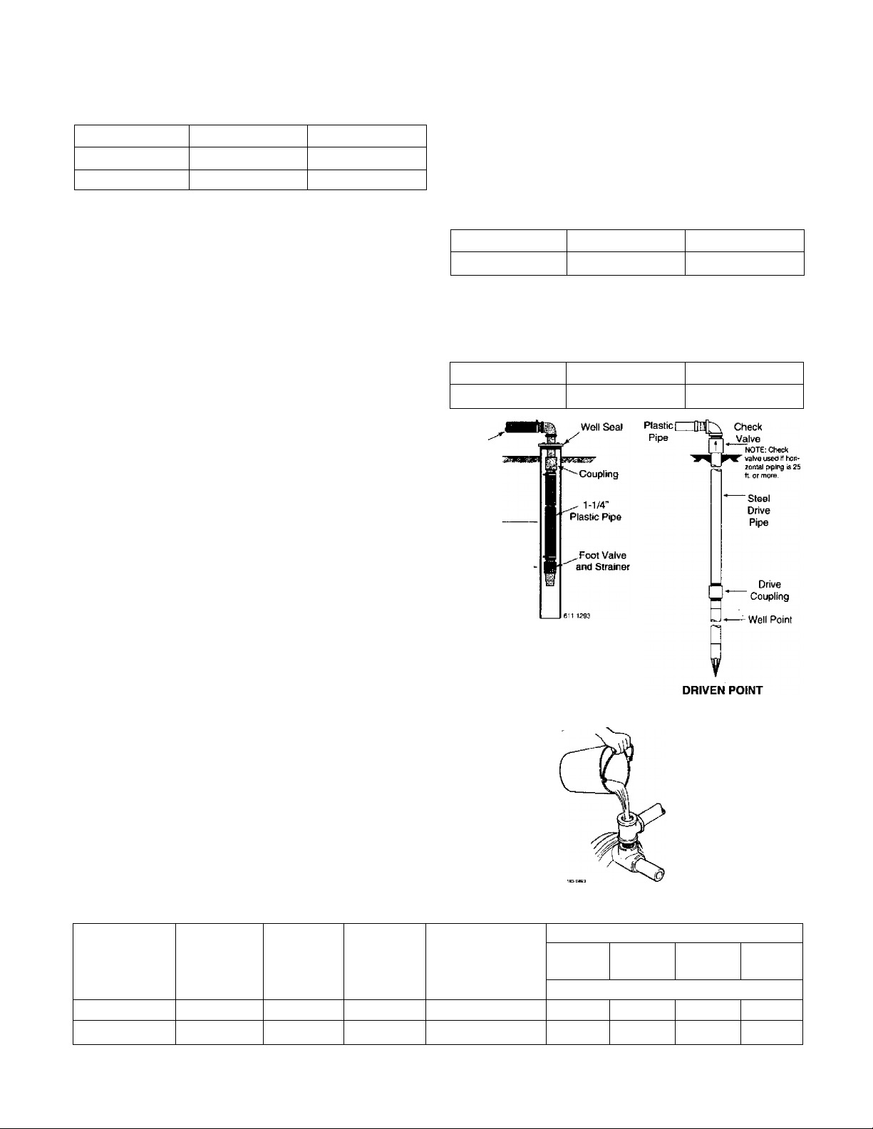
PIPING IN THE WELL
A shallow well jet pump can be installed on a dug well, drilled well
or a driven point. SEARS shallow well jet pumps have a built-in
check valve. In a dug or cased well, a foot valve and strainer should
be installed for easy priming. It should be 5 to 10 feet below the
lowest level to which the water will drop while pump is operating
(pumping level) (Figure 1).
The strainer should not be too close to the bottom, or sediment
may clog-it. Before installing foot valve, check to see that it works
freely.
When using a foot valve, a priming tee and plug must be included
(Figure 2).
Be sure the vertical distance (Uft) from the priming level to pump
is not over 20 feet, if the pump is over well. This will be less if
pump is offset from the well. Both figures are for sea level. The
maximum lift of any pump decreases with the elevation above sea
level. This decrease is at the rate of 1 foot per 1000 feet of eleva
tion, For example, the lift is 17 feet and your elevation is 3000 feet
above sea level. You would then be pumping 17 plus 3, or 20 feet.
This is still satisfactory for shallow well pumping.
Horizontal Piping from Well to Pump
On well point installations where the horizontal piping is more
than 25 feet, a check valve should be installed (Figure 3).
When the pump is offset more than 25 feet from the well, hori
zontal piping should be increased in size to reduce friction losses.
Never use offset piping that is smaller than the suction tapping of
the pump.
Horizontal Offset Piping Sizes - Shallow Well Jets
1-1/4”
Up to 25 ft. 25 to 50 ft. 50 to 200 ft.
1-1/2” 2”
Discharge Pipe Sizes
When the pump is some distance from the house or point of water
use, the discharge pipe size should be increased to reduce pressure
losses.
1”
Up to 25 ft. 25 to 100 ft. 100 to 600 ft.
1-1/4"
Plastic Pipe
S'To 10'
Pumping Level
1-1/4” 1-1/2”
_L
EMERGENCY POWER
In some areas and with some installations, an emergency power
supply to guard against power failure is a good idea. If you install
an engine-generator set for emergency backup power for your
pump, supply the generator set manufacturer with the nameplate
data from the pump motor. He wUl then be able to provide a gen
erator of the correct size to power your pump. Also, be sure to add
the load from any other accessories (such as lights) that may be on
the same circuit.
RECOMMENDED FUSING AND WIRING DATA
Motor
Pump Model
Horsepower Volts
390.251483 1/2
390.251883
3/4
115/230
115/230 12,4/6,2 20/15 12Л4
Max. Load
Amperes
10.5/5.2
DUG OR CASED WELL
FIGURE I FIGURE 3
FIGURE 2
Distance in Feet From Motor to Meter
Branch
Delayed Fuse
Rating Amps
15/15
14/14 14/14 10/14 8/14
Oto
50
51 to
100
Wire Size
12/14
101 to
200
10/14
201 to
300
8/14
Page 5

ELECTRICAL
^ Disconnect power before working on pump, motor, pressure switch, or wiring.
Your Motor Terminal Board (under the motor end cover) and
Pressure Switch look like one of those shown below. Convert to
115 Volts as shown. Do not change motor wiring if line voltage is
230 Volt to 115 Volt Conversion, Plug-in Type:
1. Pull plug
straight
out from
terminal
board.
230 Volt to 115 Volt CoriVersion, Plug-in Type:
Move plug to change voltage. ^
Power Supply Wires
2. Plug In again
with arrow
on plug
pointing to
'115 Volts'.
Grounding Point
Ground
Screw
X 230 V
115 V
®\\
3781 1000
230 Volts or if you have a single voltage motor. Connect power
supply as shown for your type of switeh and your supply voltage.
Motor wires connect here.
Power supply wires connect here.
230 Volt: Connect 2 hot wires (black and red)
here and cap the white (neutral) wire. It does
not matter which wire goes to which screw.
115 Volt: Connect one hot wire (black or red)
to one of these screws (it doesn't matter
which one). Connect the white (neutral) wire
to the other screw. Cap any remaining
black or red wires.
Clamp the power cable to prevent strain
on the terminal screws.
Connect the green (or bare copper) ground wire
to the green ground screw.
Motor wires connect here.
-Power supply wires connect here.
230 Volt: Connect 2 hot wires (black and red)
here and cap the white (neutral) wire. It does
not matter which wire goes to which screw. ■
115 Volt: Connect one hot wire (black or red)
to one of these screws (it doesn't matter
which one). Connect the white (neutral) wire
to the other screw. Cap any remaining
I- black or red wires.
Clamp the power cable to prevent strain
on the terminal screws. .
■ Connect the green (or bare copper) ground wire
to the green ground screw.
FIGURE 4: Motor wiring connections through Pressure Switch. Match motor voltage to line voltage.
LWARNING I Hazardous voltage. Can shock, bum, or kill.
Connect ground wire before connecting power supply
wires. Use the wire size (including the ground wire) speci
fied in the wiring chart. If possible, connect the pump to a sep
arate branch circuit with no other appliances on it.
A WARNING
ply line.
Explosion hazard. Do not ground to a gas sup-
WIRING CONNECTIONS
A WARNING pjj.g hazard. Incorrect voltage can cause a fire or
seriously damage the motor and voids the warranty. The supply
voltage must be within ±10% of the motor nameplate voltage.
NOTICE: Dual-voltage motors are factory wired for 230 volts. If nec
essary, reconnect the motor for 115 volts, as shown. Do not alter
the wiring in single voltage motors.
Install, ground, wire, and maintain your pump in compliance with
the National Electrical Code (NEC) or the Canadian Electrical Code
(CEC), as applicable, and with all local codes and ordinances that
apply. Consult your local building inspector for code information.
Connection Procedure:
1. Connect the ground wire first as shown in Figure 4. The ground
wire must he a solid copper wire at least as large as the power
supply wires.
2. There must be a solid metal connection between the pressure
switch and the motor for motor grounding protection. If the
pressure switch is not connected to the motor, connect the
green ground screw in the switch to the green ground screw
under the motor end cover. Use a solid copper wire at least as
large as the power supply wires.
3, Connect the ground wire to a grounded lead in a service panel,
to a metal underground water pipe, to a metal wcU casing at
least ten feet (3M) long, or to a ground electrode provided by
the power company or the hydro authority.
4, Connect the power supply wires to the pressure switch as
shown in Figure 4.
Page 6

INSTALLATION / OPERATION
INSTALLATION
SEARS jet pumps should be used with Captive Air® Tanks (See
Figure 5).
SIDE VIEW
FIGURE 5
For mounting pump to tank, purchase tank fittings Kit No. 2788.
SEARS Captive Air® Tanks are pre-chatged at the factory. Check the
tank Owners Manual to And if air charge needs adjustment. Model
390.251483 and Model 390.251883 require 40 pounds for proper
operation.
The jet pump can also be mounted on standard horizontal tanks. A
mounting kit with an AVC is furnished with tank. (Figure 6).
Instructions are also included.
SIDE
VIEW
FIGURE 6
The installation, operation, and care of your Flydroglass® Pump is
very similar to cast iron pumps. We ask, however, that you keep
the following points in mind.
NOTICE: Use Teflon tape supplied with the pump for making all
threaded connections to the pump.
DO NOT USE PIPE JOINT COMPOUND.
Wrap 1-1/2 to 2 turns of Teflon tape to all male pipe threads
being attached to the pump. This will insure leakproof connec
tions. Do not overtighten threaded fittings in the plastic pump.
If leaks do occur, remove the fitting, replace the Teflon tape,
and re wrap with 1-1/2 to 2 turns of Teflon tape and remake the
connection.
2.
Independently support aU piping connected to the Hydroglass®
Pump,
END VIEW
FIGURE 7
OPERATION
Priming the Pump
A CAUTION
water may overheat unit, damaging seals and possibly burning per
sons handling pump.
A WARNING I njjtvEn pump against closed discharge. To
do so can boil water inside pump, causing hazardous pressure in
unit and possibly scalding persons handling pump,
1. Remove priraii^ plug. Fill pump with water. Replace priming
. plug. If a priming tee and plug have been installed for a long hor
izontal run, be sure this line is filled and the plug replaced.
(Figure 2, Page 4). -
2. Start the pump. Water will be pumped in a few minutes; the
time depending upon the depth to water and length of hori
zontal run. If pump does not prime, check for a possible leak in
the suction line. Reprime. Check to be sure suction lift - dis
tance from pumping water level to pump - does not exceed 20
feet. See “Piping in the Well” on Page 4.
NEVER run pump dry. Running pump without
Page 7

SERVICE
MAtNTAINING YOUR PUMP
Lubrication
It is not necessary to lubricate the pump or its motor. The motor
bearings are lubricated for life. The mechanical shaft seal in the
pump is water lubricated and self-adjusting.
Draining for Winter
When the pump is to be disconnected from service, or is in dan
ger of freezing, it must be drained. The pump has a draincock
which must be opened. Remove the priming plug to vent the
pump. Drain the pressure tank. Drain all piping to a point below
the feezing line.
To drain an air volume control (AVC), remove the tubing. Turn the
AVC upside down. This will permit any water to drain into tank.
Disassembly and Assembly of Pump
The Hydroglass® Pump is designed for case in servicing and main
tenance.
1. Disassemble pump as follows:
A Disconnect power.
B. Op>en faucet to relieve pressure.
C. Drain pump by opening draincock. Remove pressure switch
tubing ftom fitting on top of pump.
D. Remove clamp, Key No. 10, Page 11.
E. Remove pump base mounting bolts. Motor assembly and
back half assembly of pump can be pulled away from front
half.
F. Remove O-Rings.
2. Reassembly of pump.
A. Clean O-Rings and O-Ring grooves.
B. Lubricate O-Rings with petroleum jeUy, and place in grooves.
C. Slide pump halves together.
D. Clean inside of clamp. Place clamp around pump halves.
Alternately tighten clamp screw and tap clamp around out
side with plastic mallet. This will insure proper seating of O
; Ring and clamp.
E. Assemble base mounting bolts. Connect pressure switch tub
ing and close draincock.
F. Prime pump and turn on power.
B. Loosen two screws and remove motor canopy.
C. If motor has capacitor, partially unscrew capacitor clamp and
move c:apacitor to one side. -
Risk of electrical shock. Do not touch ca
pacitor terminals with body or any metal object.
D: Hold motor shaft with a 7/16” wrench on the shaft flats.
E. Turn impeller counterclockwise when facing it.
3. Remove pump back half from motor by unscrewing four (4)
nuts. Pry back half off motor by inserting two (2) screwdrivers
between the back pump half and the motor flange. This will
force rotating portion of seal off shaft. See Figure 8.
FIGURE 8
4. Place back half of pump on flat surface and tap out ceramic seat.
Sec Figure: 9.
REMOVING MOTOR FOR SERVICE AND
REPLACING SHAFT SEAL
If it is necessary to remove motor, always replace the shaft seal. We
suggest you purchase this item, U109-6A, and have it on hand for
future use.
NOTICE: The seal consists of two parts, a rotating member and a
ceramic seat. The surfaces of the sea! arc easily damaged. Read in
structions carefully.
Remove motor as follows:
1. Disassemble pump per instructions above.
2. Remove diffuser and impeller as follows (Key Nos. 7 and 8, Page
IT).
A. Remove screws holding diffuser,
FIGURE 9
5. Clean seal cavity.
6. Install new seal.
A, Clean polished surface of ceramic seat with clean cloth.
B. Wet outer edge of O-Ring with detergent solution.
Page 8

SERVICE
C. With finger pressure press seat firmly and squarely into cav
ity. See Figure lOA. Polished face of seat faces inside of pump.
If seat wUI not locate properly, plgpe cardboard washer over
polished face and use piece of 3/4” standard pipe for press
ing purposes. See Figure’ lOB.
FIGURE lOA
FIGURE I OB
477 0194
483 0194
J. Reposition capacitor and replace motor canopy.
K. Remount diffuser on seal plate.
Cleaning Impeller
1. Follow steps lA through IE under “Disassembly and Assembly
of Pump" on Page 7.
2. Remove dififuser and impeller from pump per instructions under
“Removing Motor for Service and Replacing Shaft Seal” on Page
7.
3. Clean impeller and reassemble impeller and diffuser per in
structions under “Removing Motor for Service and Replacing
Shaft Seal” on pages 7 and 8.
Cleaning Shallow Well Jet
To remove debris from venturi or nozzle, proceed as follows:
1. Disassemble pump per instructions on Page 7.
2. Turn venturi counterclockwise and remove it. The nozzle is
now exposed. Remove it using a 5/8” hex socket wrench witli
extension. Turn counterclockwise. If socket wrench is not avail
able, insert an ice pick or similar pointed tool carefully into the
nozzle. This will dislodge debris.
3. Flush out tlie debris by running water through the nozzle in the
same direction as the dislodging tool was inserted.
4. Reinstall nozzle and venturi. Do not overtighten!
5. Reassemble pump per instructions on Page 7.
HELPFUL HINTS
How to Handle a Gaseous Well
In some areas well water contains gases which must be allowed to
escape before the water is used. This can be done as shown in
Figure 12.
D. Dispose of cardboard washer and clean surface of seat.
E. Clean motor shaft.
F. Reassemble back half of pump to motor.
G. Apply detergent solution to inside diameter of rotating seal
member.
H. Slide rotating member on shaft until rubber drive ring hits
shaft shoulder. NOTICE: BE SURE you do not chip or scratch
seal face on shaft shoulder or seal will leak!
I. Screw impeller on shaft (clockwise) while holding shaft with
7/16” open end wrench on shaft flats. This will automatically
locate seal in place. Sec Figure 11.
FIGURE 11
Gàses -
/ÌS6 !□
surface
Pipe strap orwire to hold
pipe sleeve
Not
to
Scale
Tail —
pipe
Fool-'
valve
Pipe —
sleeve
Pipe
cap
vm
Figure 12
A good way of delivering gas-free water is to suspend a pipe, closed
at the bottom and open at the top, surrounding the suction pipe.
Since the gases rise in the well casing, the water sucked down
through the pi pe and into the suction pipe is free of gas. This type
of well must be vented to the outside of any enclosure.
Air Control In Flowing Wells
Flowing wells, or wells with litde or no drawdown, could create a
special problem in air control in the operation of your water sys
tem.
In such cases, install a Captive Air® Tank. It does not require any
air control.
Page 9

TROUBLESHOOTING CHART
PROBLEM POSSIBLE CAUSES REMEDIES
Motor will not run. 1. Disconnect switch is off. 1. Be sure .switch is on.
Motor runs hot and
overload kicks off. 2. Voltage is too low. 2. Check with piower company. Install heavier wiring
Motor runs but no 1. Pump in a new installation did 1. In new installation:
water is delivered.
Pump does not
deliver water to full estimated.
capacity (also check 2. Steel piping (if used) is corroded or
point 3 inuncdiatcly
above). 3. Offset piping is too small in size.
Pump pumps water 1. Pressure switch is out of adjustment
but does not shut off.
Pump cycles too
frequently. logged and has no air cushion.
Air spurts from
faucets. 2. Leak in suction side of pump.
Leaks at the metal
clamps. not sealed.
A WARN ING
Release all pressure in system
before working on clamp.
2. Fuse is blown.
3. Starting switch is defective. 3. Replace starting switch.
4. Wires at motor are loose, 4. Refer to instructions on wiring.
disconnected, or wired incorrectly. , Check and tighten all wiring.
5. Pressure switch contacts are dirty.
1. Motor is wired incorrectly. 1. Refer to Instructions on wiring.
3. Pump cycles too frequently. 3. See section below on too frequent cycling.
not pick up prime through;
a. Improper priming. a. Re-prime according to instructions.
b. Air leaks.
c. Leaking foot valve. c. Replace foot valve.
2. Pump has lost its prime through: 2. In installation already in use;
a. Air leaks.
b. Water level below suction of pump.
3. Jet or impeller is plugged.
4. Check valve or foot valve is stuck
in closed position.
5. Pipes are frozen.
6. Foot valve and/or strainer are
buried in sand or mud.
]. Water level in well is lower than 1. A deep well jet pump may be needed
limed, causing excess friction. new stetd pipe.
or contacts are “frozen”.
2. Faucets have been left open.
3. Jet or impeller is clogged. ,
4. Water level in well is lower than
estimated.
5. Motor is wired incorrectly.
1. Standard pressure tank is water-
2. Pipes leak.
3. Faucets or valves are open.
4. Foot valve leaks.
5. Pfessure switch is out of adjustment.
6. Air charge too low in Captive Air®
Tank. Model 390.251483
and Model 390.251883 require
40 pounds for proper operation.
1. Pump is picking up prime.
3- Well is gaseous.
4. Intermittent over-pumping of well.
1. Loose clamps or ORing
2. Replace fuse.
5. Clean by sliding piece of plain paper between contacts.
if wire size is too small. See wiring instructions.
b. Check all connections on suction line, air volume
control, and jet.
a. Check all connections on suction line, air volume
contnti, jet and shaft seal.
b. Lower suction Une into water and re-prime. If receding
water level in a shallow well operation exceeds
suction lift, a deep well pump is needed.
3. Clean jet or impeUer according to instructions.
4. Replace check valve or foot valve.
5. Thaw pipes. Bury pipes below frost line. Heat pit or
pump house.
6. Raise ftxrt valve and/or strainer above well bottom.
(over 20 ft. to water).
2. Replace with plastic pipe where possible, otherwise with
3. Use larger offset piping.
1. Adjust or replace pressure switch.
2. Close faucets.
3. Clean jet or impeller.
4. Check for possibUity of using a deep weU jet pump.
5. Refer to instructions on wiring..
1. Drain tank to air volume control tapping. Check air
volume ct>ntrol for defects. Check for air leaks at any
connection.
2. Check connections.
3. Close faucets or valves.
4. Replace foot valve.
5. Adjust or replace pressure switch.
6. Disconnect electrical power and open faucets until all
pressure is reUeved. Using automobile tire pressure gauge.
check air pressure in tank at the valve stem located at top
of tank, [f air pressure is lower, pump air into tank from
outside source, until proper air pressure is reached.
Check air valve for leaks, using soapy solution, and
replace i:ore if necessary. '
1. As soon as pump picks up prime, all air will be ejected.
2. Check suction piping.
3. Change installation as described in manual.
4. Lower foot valve if possible, otherwise restrict discharge
side of pump.
1. Release alt system pressure before working on clamp.
2. Check tliat clamp is tight.
3. Tap around clamp with hammer on a wooden block.
Retighten clamp screw.
4. Check ORing for proper seating and/or dirt on
ORing or scat.
Page 10

REPAIR PARTS
Key
No.
1/2 HP
Model
390.251483
3/4 HP
Model
390.251883
Part
Description
J218-953C Motor -1/2 HP - 115/230V - 60 Cycle
-
2
17351-0009 17351-0009
J218-954C
Motor - 3/4 HP - 115/230V - 60 Cycle
Water Slinger
3* U78-107PT U78-107PT Reducer Bushing -1/2” x 1/8” NPT
3A WC78-41T WC78-41T Pipe Plug -1/8” NPT
4 L176-47P L176-47P Tank Body (Sack Half)
5 U9-399 U9-399
6
7
8
9
•
10
U109-6A U109-6A Shaft Seal
J105-40PE
J105-42PT Impeller
J1-39P J1-39P
U30-542SS
-
C19-54SS
U30-542SS
U43-21SS
C19-54SS
11 U9-201 U9-201
12 N32P-66 N32P-66E
13 N34P-19
14
N76-29P
15 J20-18
16
N176-28PB N176-28PC
N34P-17 Nozzle
N76-29P
J20-18
0-Ring - (Sq. Cut) Tank Body - 9-1/2” x 9" x 1/4”
Diffuser
Screw #8 - 32 X 7/8” (5 Required)
#8 - Star Washer (5 Required)
Clamp - Tank Body
0-Ring - Venturi -1-3/8” x 1-1/8” x 1/8"
Venturi
Insert
Gasket
Tank Body Assembly - Front Half
Includes Key No. 11.12,13,14,15,19, 20 and 23
17
18 U111-212T
19 U9-226
20 N166-5P
21* WC78-41T
22 U212-68T
23 U30-742SS
24
25* U36-37ZP
U37-673P U37-673P
U111-212T 90° Hose Barb
U9-226
N166-5P
WC78-41T
U212-68T
U30-742SS
C4-42P
C4-42P
U36-37ZP
25A U43-11ZP U43-11ZP
26 C35-11
C35-11
27 2782 2782
28
29
U36-112ZP
L43-5C L43-5C
U36-112ZP
Switch Tube
0-Ring - Check Valve - 2-1/4” x 2” x 1/8”
Check Valve
Pipe Plug -1/8” NPT (2 Required) .
Draincock -1/4” NPT
Screw - #10 -16 x 1-1/8” (4 Required)
Base
Nut - 5/16” -18 Hex Head (4 Required)
Washer - 5/16” (4 Required)
Motor Pad
Pressure Switch
Locknut -1/2”
Connector
'Standard hardware item. May be purchased locally.
"For repair or service to motors, always give the motor model number.
• Not illustrated.
10
Page 11

REPAIR PARTS
........ ..
.................
" .ip'if-
11
■ ■ . i'^ri
MfA,' €¿/1 ■
Oeiiteir. 'or .Sto№;
Page 12

SEARS
OWNER'S
MANUAL
CRAFTSMAN^
PROFESSIONAL
“HYDROGLASS”®
SHALLOW WELL
JET PUMP
MODEL NO.
390.251483
390.251883
The model number of
your Shallow Well Jet
Pump will be found on the
pump body.
When requesting service
or ordering parts, always
give the following
information:
• Product Type
• Model Number
• Part Number
• Part Description
For the repair or replacement parts you need
Call 7 am - 7 pm, 7 days a week
1 -800-366-PART
(1-800-366-7278)
For in-home major brand repair service
Call 24 hours a day, 7 days a week
1-800-4-REPAIR
(1-800-473-7247)
For the iocation of a
Sears Repair Service Center in your area
Call 24 hours a day, 7 days a week
1-800-488-1222
For information on purchasing a Sears
Maintenance Agreement or to inquire
about an existing Agreement
call 9 am - 5 pm, Monday-Saturday
1-800-827-6655
SEARS
America's Repair Spedati&ts
Sears, Roebuck and Co., Hoffman Estates, IL 60179 U.S.A.
 Loading...