

Page 1

Owner's Manual
CRAFTSMAN
55 HORSEPOWER
22 REAR DISCHARGE
POWER PROPELLED
ROTARY LAWN MOWER
Model No.
917.379480
• Safety
• Assembly
• Operation
• Maintenance
• Espa_ol
• Repair Parts
CAUTION:
Read and follow all
Safety Rules and Instructions
before operating this equipment
Sears, Roebuck and Co., Hoffman Estates, IL 60179
Visit ourCraftsman website:www.sea rs.com/craftsman
Page 2
Warranty .............................................. 2
Safety Rules ........................................ 2
Assembly ............................................. 4
Operation ............................................. 6
Maintenance Schedule ....................... 10
Maintenance ........................................ 10
LIMITED TWO YEAR WARRANTY ON CRAFTSMAN POWER MOWER
For two years from date of purchase, when this Craftsman Lawn Mower is maintained,
lubricated, and tuned up according to the operating and maintenance instructions in
the owner's manual, Sears will repair free of charge any defect in material or workman-
ship.
If.this Craftsman Lawn Mower is used for commercial or rental purposes, this warranty
applies for only 90 days from the date of purchase.
This Warranty does not cover:
• Expendable items which become worn during normal use, such as rotary mower
blades, blade adapters, belts, air cleaners and spark plug.
• Repairs necessary because of operator abuse or negligence, including bent
crankshafts and the failure to maintain the equipment according to the instructions
contained in the owner's manual.
Warranty service is available by returning the Craftsman power mower to the nearest
Sears Service Center/Department in the United States. This warranty applies only
while this product is in use in the United States.
This Warranty gives you specific legal rights, and you may also have other rights which
vary from state to state.
SEARS, ROEBUCKAND CO., D/817 WA, HOFFMAN ESTATES, ILLINOIS 60179
Product Specifications ......................... 11
Service and Adjustments ..................... 14
Storage ................................................ 16
Troubleshooting .................................. 17
Repair Parts ......................................... 37
Parts Back Cover
Safety standard's require operator
presence controls to mimimize the risk of
injury. Your unit is equipped with such
controls. Do not attempt to defeat the
function of the operator presence controls
under any circumstances.
TRAINING:
• Read this operator's manual carefully.
Become familiar with the controls and
know how to operate your mower
-properly. Learn how to quickly stop
mower.
• Do not allow children to use your
mower. Never allow adults to use mower
without proper instructions.
• Keep the area of operation clear of all
persons, especially small children and
pets.
• Use mower only as the manufacturer
intended and as described in this
manual.
• Do not operate mower if it has been
dropped or damaged in any manner.
Always have damage repaired before
using your mower.
• Do not use accessory attachments that
are not recommended by the manufac-
turer. Use of such attachments may be
hazardous.
• The blade turns when the engine is
running.
PREPARATION:
• Always thoroughly check the area to be
mowed and clear it of all stones, sticks,
wires, bones, and other foreign objects.
These objects will be thrown by the
blade and can cause severe injury.
• Always wear safety glasses or eye
shields when starting and while using
your mower.
2
Page 3
• Dress properly.Donot operate mower
when barefoot or wearing open sandals.
Wear only solid shoes with good traction
when mowing.
• Check fuel tank before starting engine.
Do not fill gas tank indoors, when the
engine is running or when the engine is
hot. Allow the engine to cool for several
minutes before filling the gas tank.
Clean off any spilled gasoline before
starting the engine.
• Always make wheel height adjustments
before starting your mower. Never
attempt to do this while the engine is
running.
• Mow only in daylight or good artificial
light.
OPERATION:
• Keep your eyes and mind on your
mower and the area being cut. Do not
let other interests distract you.
• Do not mow wet or slippery grass. Never
run while operating your mower. Always
be sure of your footing - keep a firm hold
on the handles and walk.
• Do not put hands or feet near or under
rotating parts. Keep clear of the dis-
charge opening at all times.
• Always stop the engine whenever you
leave or are not using your mower, or
before crossing driveways, walks, roads,
and any gravel-covered areas.
• Never direct discharge of material
toward bystanders nor allow anyone
near the mower while you are operating
it.
• Before cleaning, inspecting, or repairing
your mower, stop the engine and make
absolutely sure the blade and all
moving parts have stopped. Then
disconnect the spark plug wire and keep
it away from the spark plug to prevent
accidental starting.
• Do not continue to run your mower if you
hit a foreign object. Follow the proce-
dure outlined above, then repair any
damage before restarting and operating
your mower.
• Do not change the governor settings or
overspeed the engine. Engine damage
or personal injury may result.
• Do not operate your mower if it vibrates
abnormally. Excessive vibration is an
indication of damage; stop the engine,
safely check for the cause of vibration
and repair as required.
• Do not run the engine indoors. Exhaust
fumes are dangerous.
• Never cut grass by pulling the mower
towards you. Mow across the face of
slopes, never up and down or you might
lose your footing. Do not mow exces-
sively steep slopes. Use caution when
operating the mower on uneven terrain
or when changing directions - maintain
good footing.
• Never operate your mower without
proper guards, plates, grass catcher or
other safety devices in place.
MAINTENANCE AND STORAGE:
• Check the blade and the engine
mounting bolts often to be sure they are
tightened properly.
• Check all bolts, nuts and screws at
frequent intervals for proper tightness to
be sure mower is in safe working
condition
• Keep all safety devices in place and
working.
• To reduce fire hazard, keep the engine
free of grass, leaves or excessive
grease and oil.
• Check grass catcher often for deteriora-
tion and wear and replace worn bags
Use only replacement bags that are
recommended by and comply with
specifications of the manufacturer of
your mower.
• Always keep a sharp blade on your
mower.
• Allow engine to cool before storing in
any enclosure
• Never store mower with fuel in the tank
inside a building where fumes may
reach an open flame or an ignition
source such as a hot water heater,
space heater, clothes dryer, etc.
A,Look for this symbol to point out
important safety precautions It,means
CAUTION!!! BECOMEALERT!t! YOUR
SAFETY IS INVOLVED.
_CAUTION: Always disconnect spark
plug wire and place wire where it cannot
contact spark plug in order to prevent
accidental starting when setting up,
transporting, adjusting or making repairs.
_:_WARNING: The engine exhaust from
this product contains chemicals known to
the State of California to cause cancer,
birth defects, or other reproductive harm.
3
Page 4
These accessories were available when this lawn mower was produced, are not
shipped with your mower. They are also availableat most Sears retailoutletsand service
centers. Most Sears stores can also order repair parts for you, when you provide the model
number of your lawn mower. Some ofthese accessories may not apply to your lawn mower.
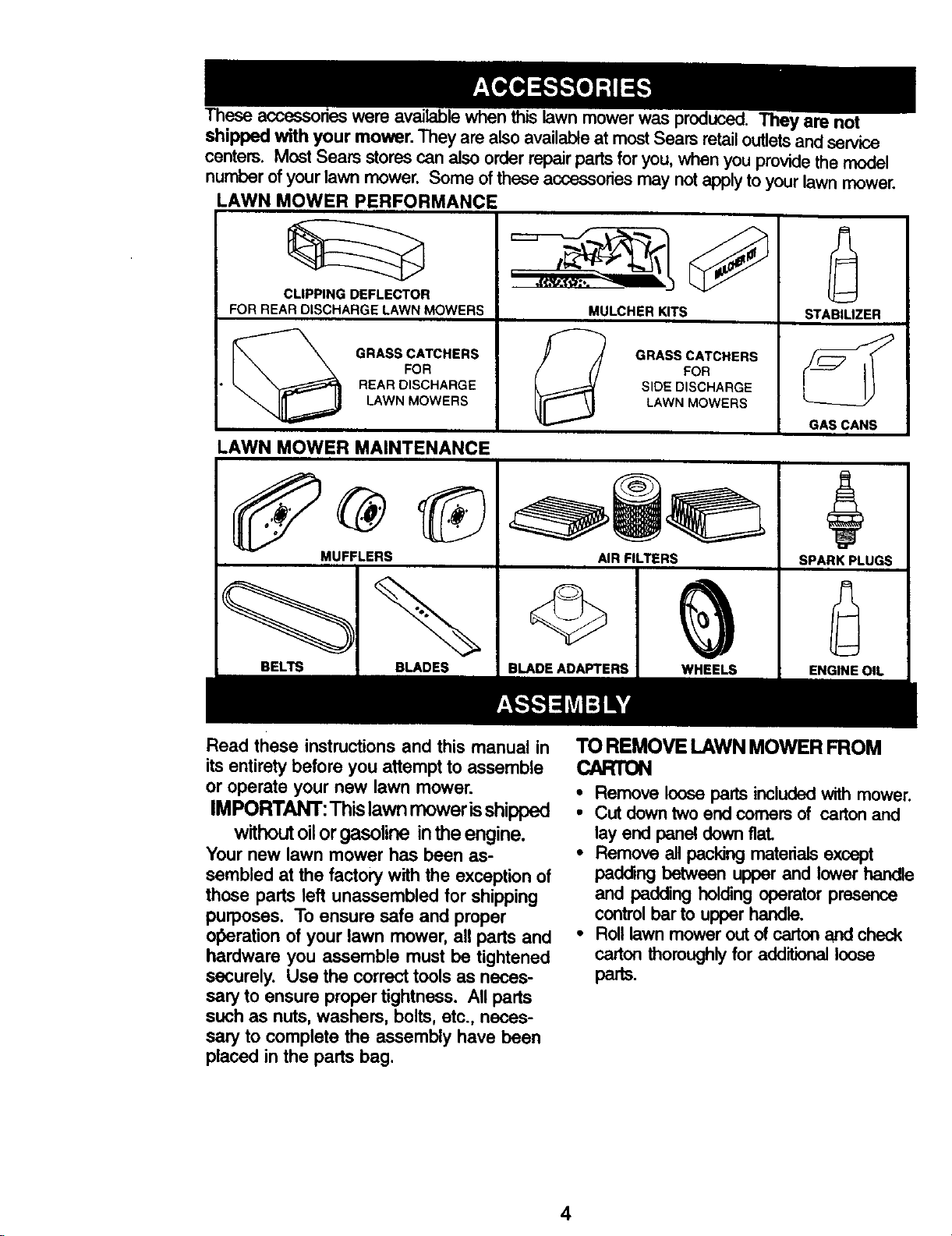
LAWN MOWER PERFORMANCE
CLIPPING DEFLECTOR
FOR REAR DISCHARGE LAWN MOWERS
GRASS CATCHERS
FOR
REAR DISCHARGE
LAWN MOWERS
LAWN MOWER MAINTENANCE
MUFFLERS
BELTS BLADES
,f(.vi.l_=*,. -
MULCHERK_S
FOR
SIDE DISCHARGE
GRASS CATCHERS
LAWN MOWERS
AIR FILTERS
BLADE ADAFrERS WHEELS
STABILIZER
GAS CANS
SPARK PLUGS
ENGINE OIL
Read these instructions and this manual in
its entirety before you attempt to assemble
or operate your new lawn mower.
IMPORTANT: This lawn mower is shipped
without oil or gasoline in the engine.
Your new lawn mower has been as-
sembled at the factory with the exception of
those parts left unassembled for shipping
purposes. To ensure safe and proper
olberation of your lawn mower, all parts and
hardware you assemble must be tightened
securely. Use the correct tools as neces-
sary to ensure proper tightness. All parts
such as nuts, washers, bolts, etc., neces-
sary to complete the assembly have been
placed in the parts bag.
TOREMOVE LAWNMOWERFROM
CARTON
• Remove loose parts included with mower.
• Cutdowntwoendcomersof cartonand
layendpanadownfiat
• Remove all pacldng materials except
padding between upper and lower handle
and padding holding operator presence
control bar to upper handle.
• Roll lawn mower out of carton and check
carton thoroughly for additional loose
parts.
4
Page 5
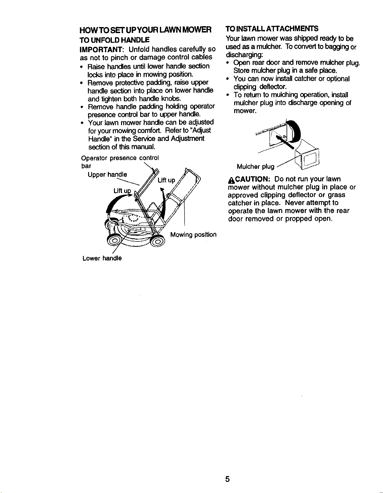
HOWTO SETUPYOUR LAWNMOWER
TO UNFOLD HANDLE
IMPORTANT: Unfold handles carefully so
as not to pinch or damage control cables
• Raise handles until lower handle section
locks into place in mowing position.
• Remove protective padding, raise upper
handle section into place on lower handle
and tighten both handle knobs.
• Remove handle padding holding operator
presence control bar to upper handle.
• Your lawn mower handle can be adjusted
for your mowing comfort. Refer to "Adjust
Handle" in the Service and Adjustment
section of this manual.
TO INSTALL ATTACHMENTS
Your lawn mower was shipped ready to be
used as a mulcher. To convert to bagging or
discharging:
• Open rear door and remove muleher plug.
Store mulcher plug in a safe place.
• You can now installcatcher or optional
clipping deflector.
• To retum to mulching operation, install
mulcher plug into discharge opening of
mower.
Operator presence control
bar
Upper handle _ _
• ,fup/
Lower handle
Mulcher plug ,__
ACAUTION: Do not run your lawn
mower without mulcher plug in place or
approved clipping deflector or grass
catcher in place. Never attempt to
operate the lawn mower with the rear
door removed or propped open.
Mowing position
5
Page 6
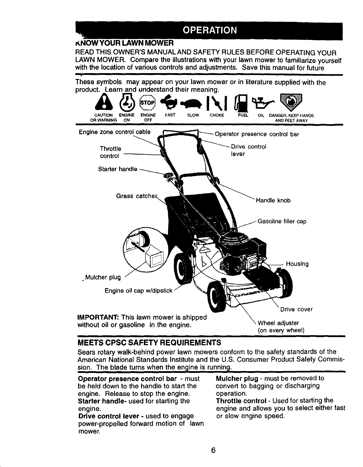
_NOWYOUR LAWN MOWER
READ THIS OWNER'S MANUALAND SAFETY RULES BEFORE OPERATING YOUR
LAWN MOWER. Compare the illustrations with your lawn mower to familiarize yourself
with the location of various controls and adjustments. Save this manual for future
°
These symbols may appear on your lawn mower or in literature supplied with the
product. Learn and understand their meaning.
CAUTION ENGfNE ENGINE FAST SLOW CHOKE FUEL OIL DANGER, KEEPHANDS
OR WARNING ON OFF AND FEET AWAY
I
Engine zone controlcable
Throttle
control
Grass catcher_,
• Mulcher plug
Engine oil ca_:
)resence control bar
_Drive control
lever
Handle knob
Housing
Drive cover
IMPORTANT: This lawn mower is shipped
without oilor gasoline in the engine.
, Wheel adjuster
(on every wheel)
MEETS CPSC SAFETY REQUIREMENTS
Sears rotary walk-behind power lawn mowers conformto the safety standards of the
American National Standards Institute and the U.S, Consumer ProductSafety Commis-
sion. The blade turns when the en_]ineis running,
Operator presence control bar - must
be held down to the handle to start the
engine. Release to stop the engine.
Starter handle- used for starting the
engine.
Drive control lever - used to engage
power-propelled forward motion of lawn
mower.
Mulcher plug - must be removed to
convert to bagging or discharging
operation.
Throttle control - Used for starting the
engine and allows you to select either fast
or slow engine speed.
6
Page 7
The operation of any lawn
mower can result in foreign
objects thrown into the eyes,
which can result in severe eye damage.
Always wear safety glasses or eye
shields while operating your lawn mower
or performing any adjustments or repairs.
We recommend a wide vision safety
mask over spectacles or standard safety
glasses.
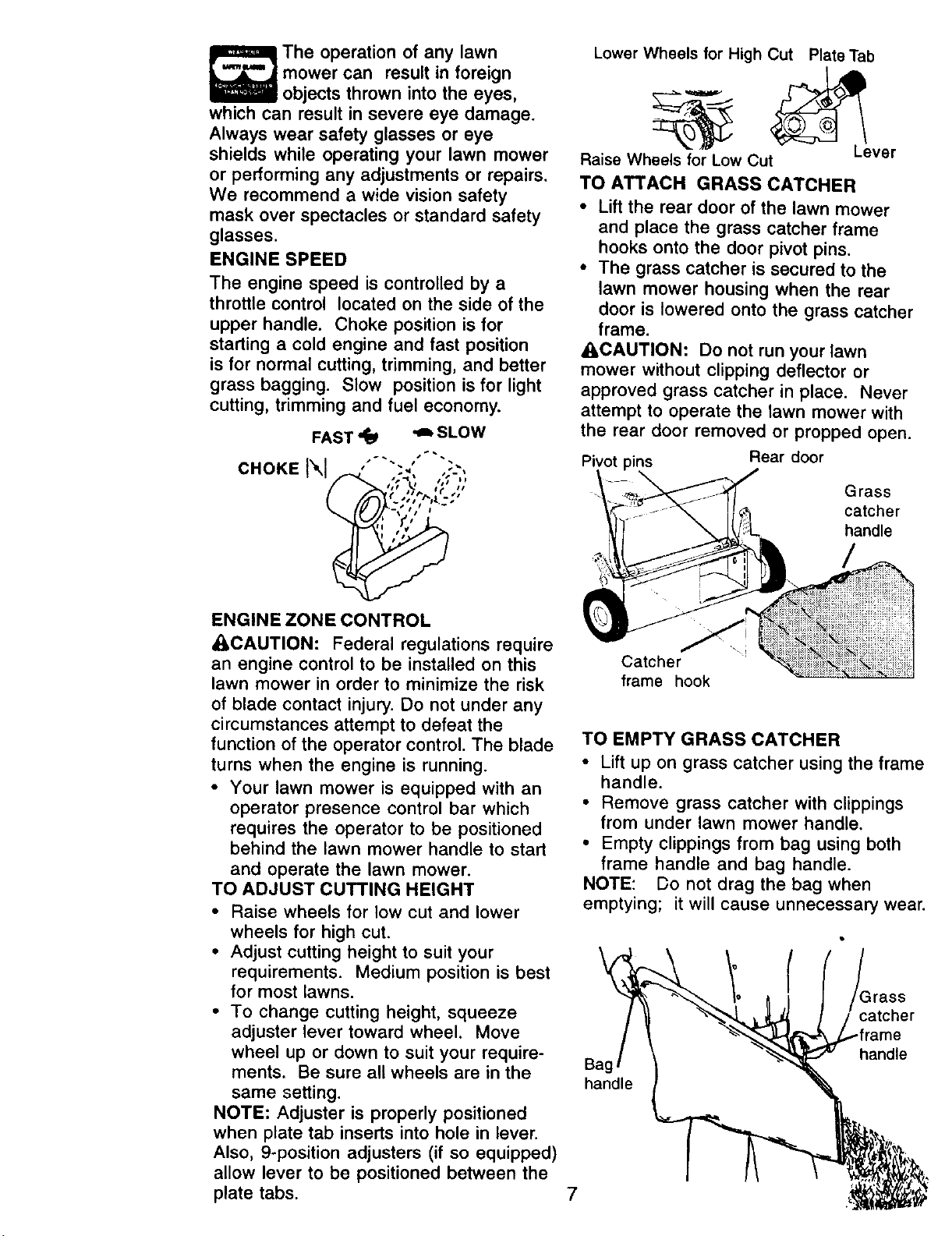
ENGINE SPEED
The engine speed is controlled by a
throttle control located on the side of the
upper handle. Choke position is for
starting a cold engine and fast position
is for normal cutting, trimming, and better
grass bagging. Slow position is for light
cutting, trimming and fuel economy.
FAST _ _ SLOW
CHOKE '" "'" ' ""
•.-,; ,,,; .
#11 L II
Lower Wheels for High Cut PlateTab
Raise Wheels for Low Cut
Lever
TO ATTACH GRASS CATCHER
• Lift the rear door of the lawn mower
and place the grass catcher frame
hooks onto the door pivot pins.
• The grass catcher is secured to the
lawn mower housing when the rear
door is lowered onto the grass catcher
frame.
_I,CAUTION: Do not run your lawn
mower without clipping deflector or
approved grass catcher in place. Never
attempt to operate the lawn mower with
the rear door removed or propped open.
Pivot _ins
Rear door
Grass
catcher
handle
ENGINE ZONE CONTROL
_CAUTION: Federal regulations require
an engine control to be installed on this
lawn mower in order to minimize the risk
of blade contact injury. Do not under any
circumstances attempt to defeat the
function of the operator control. The blade
turns when the engine is running.
• Your _awn mower is equipped with an
operator presence control bar which
requires the operator to be positioned
behind the lawn mower handle to start
and operate the lawn mower.
TO ADJUST CUTTING HEIGHT
• Raise wheels for low cut and lower
wheels for high cut.
• Adjust cutting height to suit your
requirements. Medium position is best
for most lawns.
• To change cutting height, squeeze
adjuster lever toward wheel. Move
wheel up or down to suit your require-
ments. Be sure all wheels are in the
same setting.
NOTE: Adjuster is properly positioned
when plate tab inserts into hole in lever.
Also, 9-position adjusters (if so equipped)
allow lever to be positioned between the
plate tabs.
/
Catcher
frame hook
TO EMPTY GRASS CATCHER
• Lift up on grass catcher using the frame
handle.
• Remove grass catcher with clippings
from under lawn mower handle,
• Empty clippings from bag using both
frame handle and bag handle.
NOTE: Do not drag the bag when
emptying; it will cause unnecessary wear
_rass
catcher
*frame
handle
ga¢
handle
7
Page 8
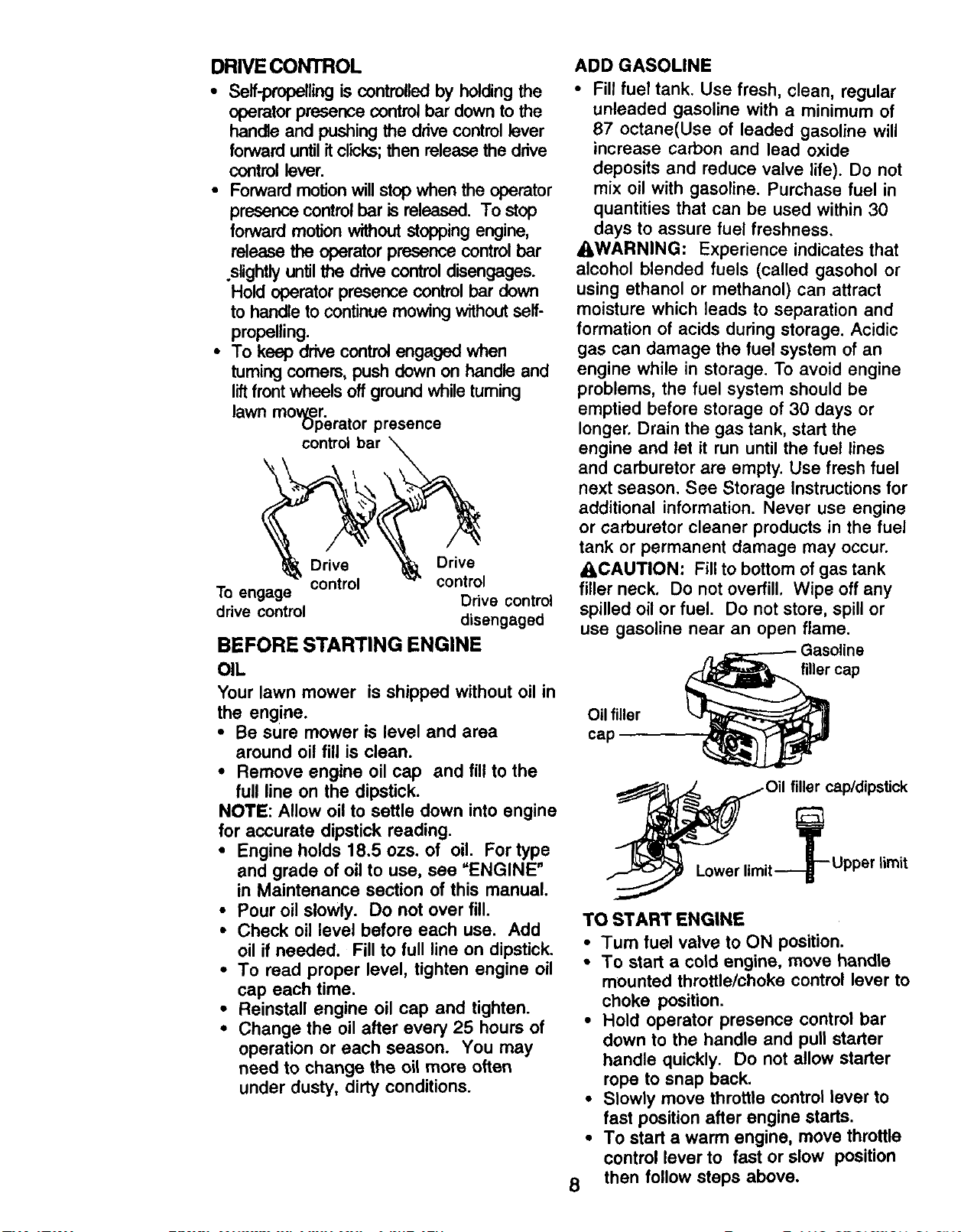
DRIVE CONTROL
• Self-propelling is controlled by holding the
operator presence control bar down to the
handle and pushing the drive control lever
forward until it clicks;then release the drive
control lever.
• Forward motion will stop when the operator
presence control bar is released. To stop
forward motion without stopping engine,
release the operator presence control bar
slightly until the drive control disengages.
Hold operator presence control bar down
to handle to continue mowing without self-
propelling.
• To keep drive control engaged when
turningcomers, push down on handle and
liftfront wheels off ground while turning
lawn mower.
Operator presence
controlbar
Drive Drive
control control
To engage Drive control
drive control disengaged
BEFORE STARTING ENGINE
OIL
Your lawn mower is shipped without oil in
the engine.
• Be sure mower is level and area
around oil fill is clean.
• Remove engine oil cap and fill to the
full line on the dipstick.
NOTE: Allow oil to settle down into engine
for accurate dipstick reading.
• Engine holds 18.5 ozs. of oil. For type
and grade of oil to use, see "ENGINE"
in Maintenance section of this manual.
• Pour oil slowly. Do not over fill.
• Check oil level before each use. Add
oil if needed. Fill to full line on dipstick.
• To read proper level, tighten engine oil
cap each time.
• Reinstall engine oil cap and tighten.
• Change the oil after every 25 hours of
operation or each season. You may
need to change the oil more often
under dusty, dirty conditions.
ADD GASOLINE
• Fill fuel tank. Use fresh, clean, regular
unleaded gasoline with a minimum of
87 octane(Use of leaded gasoline will
increase carbon and lead oxide
deposits and reduce valve life). Do not
mix oil with gasoline. Purchase fuel in
quantities that can be used within 30
days to assure fuel freshness.
AWARNING: Experience indicates that
alcohol blended fuels (called gasohol or
using ethanol or methanol) can attract
moisture which leads to separation and
formation of acids during storage. Acidic
gas can damage the fuel system of an
engine while in storage. To avoid engine
problems, the fuel system should be
emptied before storage of 30 days or
longer, Drain the gas tank, start the
engine and let it run until the fuel lines
and carburetor are empty. Use fresh fuel
next season. See Storage Instructions for
additional information. Never use engine
or carburetor cleaner products in the fuel
tank or permanent damage may occur.
_IbCAUTION: Fill to bottom of gas tank
filler neck, Do not overfill, Wipe off any
spilled oil or fuel. Do not store, spill or
use gasoline near an open flame.
filler cap
Oil filler
cap
__ __-Oil filler cap/dipstick
Lowerlimit----_ -Upper limit
J
J
TO START ENGINE
•Tum fuel valve to ON position.
• To start a cold engine, move handle
mounted throttle/choke control lever to
choke position.
• Hold operator presence control bar
down to the handle and pull starter
handle quickly. Do not allow starter
rope to snap back.
• Slowly move throttle control lever to
fast position after engine starts.
• To start a warm engine, move throttle
control lever to fast or slow position
8 then follow steps above.
Page 9
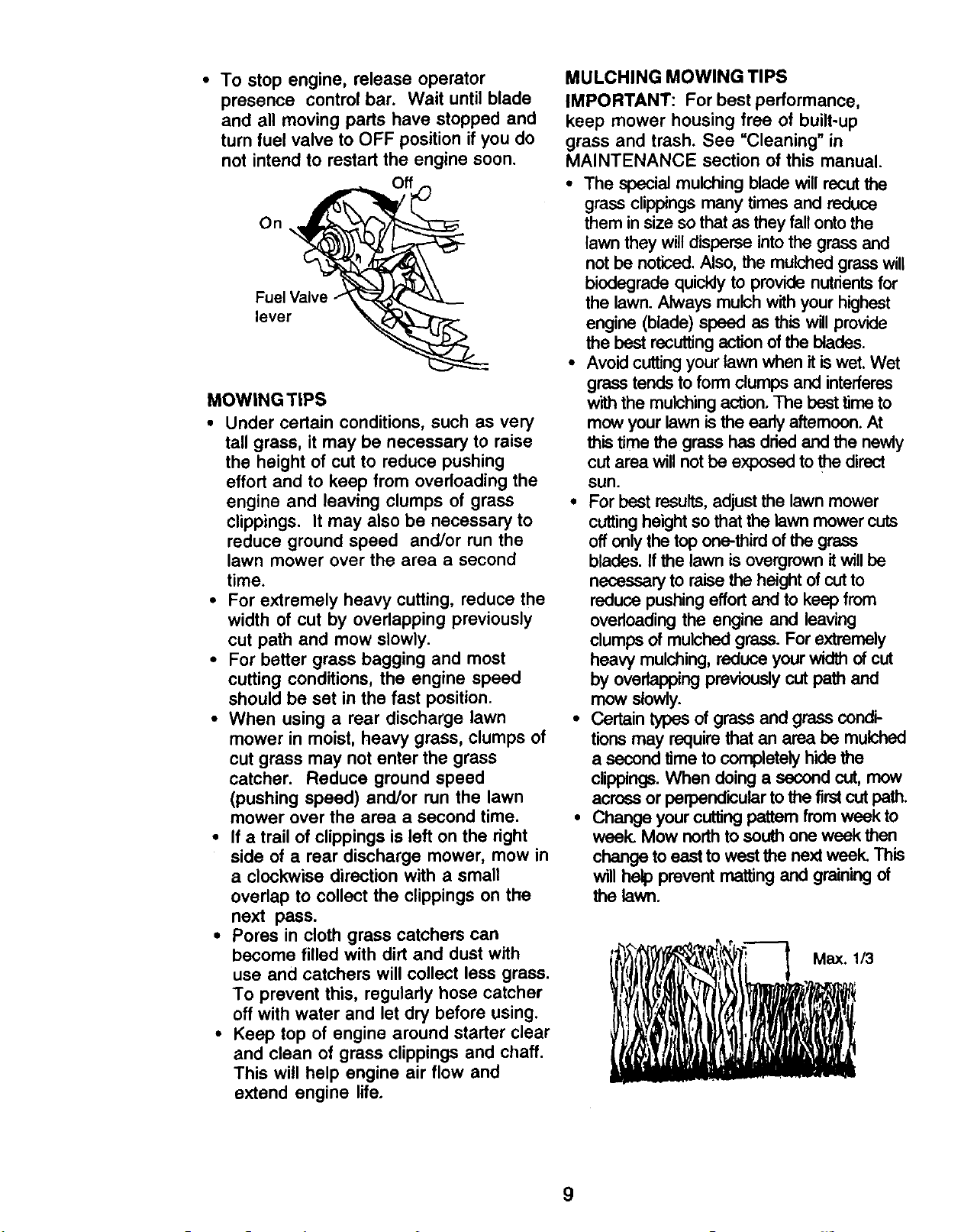
• To stop engine, release operator
presence control bar. Wait until blade
and all moving parts have stopped and
turn fuel valve to OFF position if you do
not intend to restart the engine soon.
On
Fuel Valve
lever
MOWING TIPS
• Under certain conditions, such as very
tall grass, it may be necessary to raise
the height of cut to reduce pushing
effort and to keep from overloading the
engine and leaving clumps of grass
clippings. It may also be necessary to
reduce ground speed and/or run the
lawn mower over the area a second
time.
• For extremely heavy cutting, reduce the
width of cut by overlapping previously
cut path and mow slowly.
• For better grass bagging and most
cutting conditions, the engine speed
should be set in the fast position.
• When using a rear discharge lawn
mower in moist, heavy grass, clumps of
cut grass may not enter the grass
catcher. Reduce ground speed
(pushing speed) and/or run the lawn
mower over the area a second time.
• If a trail of clippings is left on the right
side of a rear discharge mower, mow in
a clockwise direction with a small
ovedap to collect the clippings on the
next pass.
• Pores in cloth grass catchers can
become filled with dirt and dust with
use and catchers will collect less grass.
To prevent this, regularly hose catcher
off with water and let dry before using.
• Keep top of engine around starter clear
and clean of grass clippings and chaff.
This will help engine air flow and
extend engine life.
MULCHING MOWING TIPS
IMPORTANT: For best performance,
keep mower housing free of built-up
grass and trash. See =Cleaning" in
MAINTENANCE section of this manual.
• The special mulching blade will recutthe
grass clippings many times and reduce
them in size so that as they fall ontothe
lawn they will disperse intothe grass and
not be noticed. Also, the mulched grass will
biedegrade quickly to provide nutrientsfor
the lawn. Always mulch with your highest
engine (blade) speed as this will provide
the best recuttingaction of the blades.
• Avoid cuttingyour lawn when it iswet. Wet
grass tends to form dumps and interferes
with the mulching action. The best time to
mow your lawn is the eady aftemcon. At
this time the grass has dried and the newly
cut area will not be exposed to the direct
sun.
• For best results,adjust the lawn mower
cutting height so that the lawn mower cuts
off only the top one-third of the grass
blades. If the lawn is overgrown it will be
necessary to raise the height of cutto
reduce pushing effort and to keep from
overloading the engine and leaving
clumps of mulched grass. For extremely
heavy mulching, reduce your width of cut
by overlapping previously cut path and
mow slowly.
• Certain types of grass and grass condi-
tions may require that an area be mulched
a second time to completely hide the
clippings.When doing a second cut, mew
across or perpendicular tothe firstcutpath.
• Change your cutting pattem from week to
week. Mow northto south one week then
change to east to west the next week. This
willhelp prevent matting and graining of
the lawn.
9
Page 10
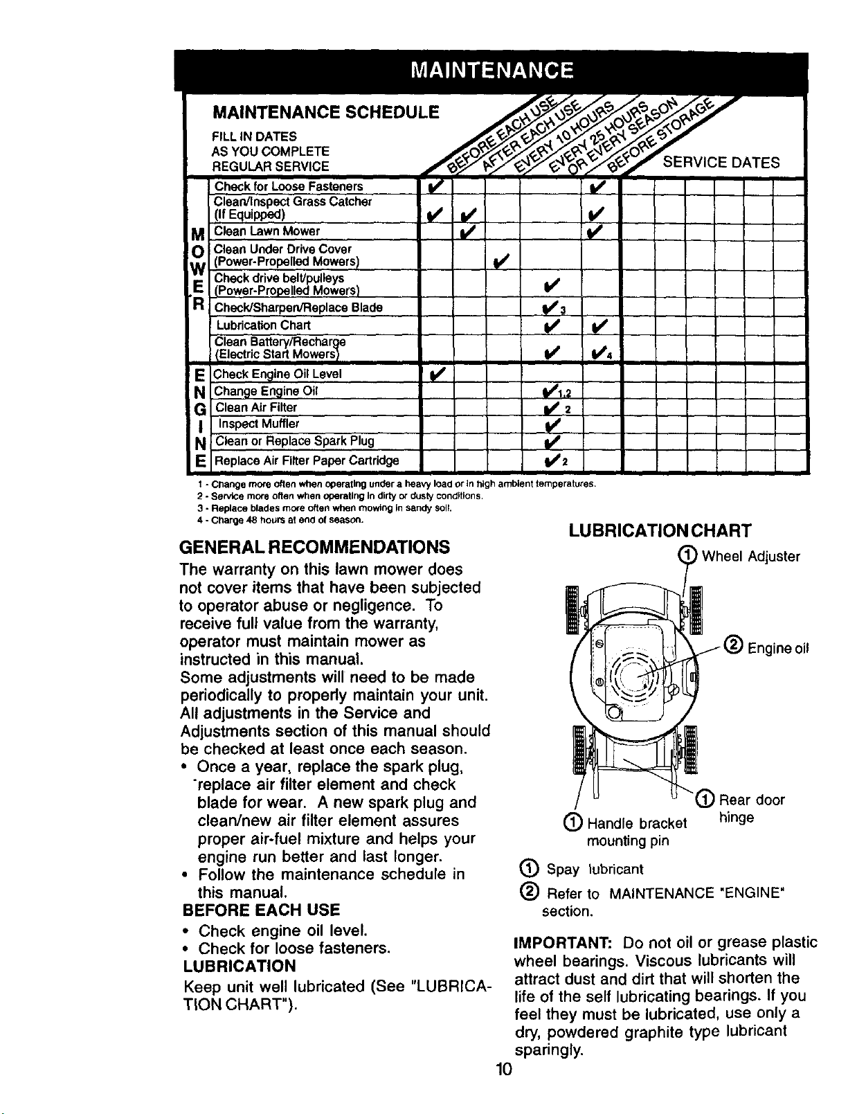
MAINTENANCE SCHEDULE
FILLIN DATES
AS YOU COMPLETE
REGULAR SERVICE
Check for Loose Fasteners !/
Clean/Inspect Grass Catcher
(If Equipped) ¥/ _
oM Clean Lawn Mower
Clean Under Drive Cover
(Power-Propelled Mowers)
W Check drive belt/pulleys
(Power-Propelled Mowers} ¥/
R Check/Sharpen/Replace Blade . .Ip#.3
Lubrication Chart I_ If#
Clean Battery/Recharge
IElectric Start Mowers I I/ 1/14
NE Check Engine Oil Level !/
Change Engine Oil I/1.2
Inspect Muffler ....
Clean Air Filter _2
N; Clean or Replace Spark Plug
Replace Air Filter Paper Cartridge I/2
I - Change mote often when operating under a heavy load or in high ambient temperatures.
2 - Servicemoreoftenwhenoperatingin dirtyOrdusty conditions.
3 - Replace blades more often when mowing In sandy SOIL
4 - Charge48 hours at end orseason.
,ll
GENERAL RECOMMENDATIONS
The warranty on this lawn mower does
not cover items that have been subjected
to operator abuse or negligence. To
receive full value from the warranty,
operator must maintain mower as
instructed in this manual.
Some adjustments will need to be made
periodically to properly maintain your unit.
All adjustments in the Service and
Adjustments section of this manual should
be checked at least once each season.
• Once a year, replace the spark plug,
"replace air filter element and check
blade for wear. A new spark plug and
clean/new air filter element assures
proper air-fuel mixture and helps your
engine run better and last longer.
• Follow the maintenance schedule in
this manual.
(_ Spay lubricant
(_) Refer to MAINTENANCE "ENGINE"
BEFORE EACH USE
• Check engine oil level.
• Check for loose fasteners.
LUBRICATION
Keep unit well lubricated (See "LUBRICA-
TION CHART").
IMPORTANT: Do not oil or grease plastic
wheel bearings. Viscous lubricants will
attract dust and dirt that will shorten the
life of the self lubricating bearings. If you
feel they must be lubricated, use only a
dry, powdered graphite type lubricant
sparingly.
10
SERVICE DATES
LUBRICATION CHART
Wheel Adjuster
ine oil
(_ Rear door
(_) Handle bracket hinge
mounting pin
section.
Page 11

PRODUCT SPECIFICATIONS
SERIAL NUMBER
DATE OF PURCHASE
GASOLINE CAPACITY/TYPE:
JNLEADED REGULAR
OIL TYPE (API-SF/SG/SH):
OIL CAPACITY:
SPARK PLUG(GAP: .030")
VALVE CLEARANCE:
SOLID STATE IGNITION
AIR GAP: .010 IN.
BLADE BOLT TORQUE: 35-40 FT. LBS.
• The model and serial numbers will be found on a decal attached to the rear of the
lawn mower housing.Record both serial number and date of purchase in space
provided above.
1.0 QUARTS
SAE 30 (ABOVE 32°F)
SAE 5W-30 (BELOW 32°F)
18.50ZS.
CHAMPIONR J19LM OR J19LM
INTAKE: .005" - .007"
EXHAUST: .007" - .009"
LAWN MOWER
Always observe safety rules when
performing any maintenance.
TIRES
• Keep tires free of gasoline, oil, or insect
control chemicals which can harm
rubber.
• Avoid stumps, stones, deep ruts, sharp
objects and other hazards that may
cause tire damage.
BLADE CARE
For best results, mower blade must be
kept sharp. Replace bent or damaged
blades.
TO REMOVE BLADE
• Disconnect spark plug wire from spark
plug and place wire where it cannot
come in contact with spark plug.
• Turn lawn mower on its side. Make
sure air filter and carburetor are up.
• Use a wood block between blade and
mower housing to prevent blade from
turning when removing blade bolt.
• Protect your hands with gloves and/or
wrap blade with heavy cloth.
• Remove blade bolt by turning counter-
clockwise. Use a 9/16" box or open-
end wrench.
• Remove blade and attaching hard-
ware.
TO REPLACE BLADE
• Position the blade adapter on the
engine crankshaft. Be sure the spacer
is in the adaptor and key in shaft and
adaptor keyway are aligned.
• Position blade on the blade adapter.
Be sure the trailing edge of blade
(opposite sharp edge) is up toward the
engine.
• Install the blade bolt with washers into
blade adapter and crankshaft.
• Use block of wood between blade and
lawn mower housing and tighten the
blade bolt, turning clockwise.
• The recommended tightening torque is
35-40 ft. Ibs.
IMPORTANT: BLADE BOLT IS GRADE 8
HEATTREATED.
TO SHARPEN BLADE
NOTE: We do not recommend sharpen-
ing blade - but if you do, be sure the
blade is balanced.
Care should be taken to keep the blade
balanced. An unbalanced blade will
cause eventual damage to lawn mower
or engine.
• The blade can be sharpened with a file
or on a grinding wheel. Do not attempt
to sharpen while on the mower.
11
Page 12

• To check blade balance, drive a nail
into a beam or wall. Leave about one
inch of the straight nail exposed. Place
center hole of blade over the head of
the nail. If blade is balanced, it should
remain in a horizontal position. If either
end of the blade moves downward,
sharpen the heavy end until the blade
is balanced.
Lockwasher Spacer
Blade Sic
Blade washer
bolt Trailing/edge adapter
GRASS CATCHER
• The grass catcher may be hosed with
water, but must be dry when used.
• "Check your grass catcher often for
damage or deterioration. Through
normal use it will wear. If catcher
needs replacing, replace only with a
manufacturer approved replacement
catcher. Give the lawn mower model
number when ordering.
DRIVE WHEELS
Check front drive wheels each time
before you mow to be sure they move
freely.
The wheels not turning freely means
trash, grass cuttings, etc. are in the drive
wheel area and must be cleaned to free
drive wheels.
If necessary to clean the drive wheels,
check both front wheels.
,, Remove hubcaps, hairpin cotters and
washers.
• Remove wheels from wheel adjusters.
• Remove any trash or grass cuttings
from inside the dust cover, pinion and/
or drive wheel gear teeth.
• Put wheels back in place.
• If after cleaning, the drive wheels do
not turn freely, contact your nearest
.authorized service center.
GEAR CASE
• To keep your drive system working
properly, the gear case and area
around the drive should be kept clean
and free of trash build-up. Clean under
the drive cover twice a season.
• The gear case is filled with lubricant to
the proper level at the factory. The only
time the lubricant needs attention is if
service has been performed on the
gear case.
• If lubricant is required, use only Texaco
Starplex Premium 1 Grease, Part No.
750369. Do not substitute.
ENGINE
LUBRICATION
Use only high quality detergent oil rated with
API service classif_tion SI-, SG or SH.
Select the oil's SAE v'_,osily grade according
to your expected operating temperature.
SAE VISCOSITY GRADES
O.
._ .10. O* I0. 20" 3_,
TEMPERATURE RANGE ANTICtPAT_D BEFORE NEXT OIL CHANGE
NOTE: Although multi-viscosity oils (5W30,
10W30 etc.) improve startingin cold weather,
these multi-viscosityoilswill result in
increased oil consumption when used above
32°F. Check your engine oil level more
frequen T to avoid possible engine damage
from running low on oil.
Change the oil after every 25 hoursof
operation or at least once a year ifthe lawn
mower is not used for 25 hours inone year.
Check the crankcase oil levelbefore starting
the engine and after each five (5) hours of
continuous use. Tighten oil plugsecurely
each time you check the oil level.
TO CHANGE ENGINE OIL
NOTE: Before tipping lawn mower to
drain oil, drain fuel tank by running
engine until fuel tank is empty.
• Disconnect spark plug wire from spark
plug and place wire where it cannot
come in contact with spark plug.
• Remove engine oil cap; lay aside on a
clean surface.
• Tip lawn mower on its side as shown
and drain oil into a suitable container.
Rock lawn mower back and forth to
remove any oil trapped inside of
engine.
• Wipe off any spilled oil on lawn mower
and on side of engine.
• Fill engine with oil. Fill to the upper
limit mark on the dipstick. DO NOT
OVER FILL.
12
Page 13

• To read proper level, insert the dipstick
into the tube and rest oil fill cap on the
tube. Do not thread thecap onto the
tube. Remove and read the oil level.
• Replace engine oil cap.
• Reconnect spark plug wire to spark
plug.
Oil filler cap/dipstick
__Upper limit
_Lower limit
AIR FILTER
Your engine will not run properly and may
be damaged by using a dirty air filter.
Replace the air filter every year, more
often if you mow in very dusty, dirty
conditions.
TO CLEAN AIR FILTER
• Remove cover.
• Carefully remove cartridge.
• Clean by gently tapping on a flat
surface. If very dirty, replace cartridge.
ACAUTION: Petroleum solvents, such
as kerosene, are not to be used to clean
cartridge. They may cause deterioration
of the cartridge. Do not oil cartridge. Do
not use pressurized air to clean or dry
cartridge.
• Install cartridge, then replace cover.
Filter
Filter
Tabs Cover
MUFFLER
Inspect and replace corroded muffler as it
could create a fire hazard and/or dam-
age.
SPARK PLUG
Change your spark plug each year to
make your engine start easier and run
better. Set spark plug gap at .030 inch.
CLEANING
IMPORTANT: For best performance,
keep mower housing free of built-up
grass and trash. Clean the underside of
your mower after each use.
ACAUTION: Disconnect spark plug wire
from spark plug and place wire where it
cannot come in contact with the spark
plug.
• Tum lawn mower on itsside. Make sure air
filter and carburetor are up. Clean the
underside of your lawn mower by scraping
to remove buildup of grass and trash.
• Clean engine often to keep trash from
accumulating. A clogged engine runs
hotter and shortens engine life.
• Keep finished surfaces and wheels free of
all gasoline, oil,etc.
• We de not recommend usinga garden
hose to clean lawn mower unless the
electricalsystem, muffler,air filterand
carburetor are covered to keep water out.
Water in engine can resultin shortened
engine life.
CLEAN UNDER DRIVE COVER
Clean under ddve cover at least twice a
season. Scrape underside ofcover with putty
knife or similar tool to remove any buildupof
trash or grass on underside of drivecover.
Tabs
13
Page 14

ACAUTION: Before performing
anyservice or adjustments.
• Release control bar and stop engine.
• Make sure the blade and all moving
parts have completely stopped.
• Disconnect spark plug wire from spark
plug and place where it cannot come in
contact with plug.
LAWN MOWER
TO ADJUST CUTTING HEIGHT
See "TO ADJUST CUTTING HEIGHT" in
the Operation section of this manual.
REAR DEFLECTOR
The rear deflector, attached between the
rear wheels of your lawn mower, is
provided to minimize the possibility that
objects will be thrown out the rear of the
lawn mower into the operator's mowing
position. If the rear deflector becomes
damaged, it should be replaced.
TO REMOVFJREPLACE DRIVE BELT
• Remove drive cover. Remove belt by
pushing down on gear case pulley and
rolling belt off it.
• Turn lawn mower on its side with
carburetor and fuel cap up.
• Remove blade.
• Remove debris shield.
• Remove belt from engine pulley on
crankshaft.
• Install new belt by reversing above
steps.
• Always use factory approved belt to
assure fit and long life.
TO ADJUST HANDLE
The upper handle may be adjusted to four
(4) different height positions.
° Loosen both handle knobs only enough
to allow the upper handle to pivot to the
desired adjustment position..
• Tighten both handle knobs securely.
Handle Knob
Handle Knob
TO ASSEMBLE GRASS CATCHER
• Put grass catcher frame into grass bag
with rigid part of bag on the bottom.
Make sure the frame handle is outside
of the bag top.
• Slip vinyl bindings over frame.
NOTE: If vinyl bindings are too stiff, hold
them in warm water for a few minutes. If
bag gets wet, let it dry before using.
_,CAUTION: Do not run your lawn mower
without clipping deflector or approved
grass catcher in place. Never attempt to
operate the lawn mower with the rear
door removed or propped open.
Drive
cover Belt
Push
down
Catcher
frame
handle
•Frame
opening
14
Page 15

ENGINE
ENGINE SPEED
Your engine speed has been factory set.
Do not attempt to increase engine speed
or it may result in personal injury. If you
believe that the engine is running too fast
or too slow, take your lawn mower to an
authorized service center for repair and
adjustment.
CARBURETOR
Your carburetor is not adjustable. If your
engine does not operate properly due to
suspected carburetor problems, take your
lawn mower to an authorized service
center for repair and/or adjustment.
IMPORTANT: Never tamper with the
engine governor, which is factory set for
proper engine speed. Overspeeding the
engine above the factory high speed
setting can be dangerous. If you think the
engine-governed high speed needs
adjusting, contact your nearest
authorized service center, which has
proper equipment and experience to
make any necessary adjustments.
15
Page 16

Immediately prepare your lawn mower for
storage at the end of the season or if the
unit will not be used for 30 days or more.
LAWNMOWER
When lawn mower is to be stored for a
period of time, clean it thoroughly, remove
all dirt, grease, leaves, etc. Store in a
clean, dry area.
• Clean entire lawn mower (See
"CLEANING" in the Maintenance
"section of this manual).
• Lubricate as shown in the Maintenance
section of this manual.
• Be sure that all nuts, bolts, screws, and
pins are securely fastened. Inspect
moving parts for damage, breakage
and wear. Replace if necessary.
• Touch up all rusted or chipped paint
surfaces; sand lightly before painting.
HANDLE
You can fold your lawn mower handle for
storage.
• Squeeze the bottom ends of the lower
handle toward each other until the
lower handle clears the handle bracket,
then move handle forward.
• Loosen upper handle mounting bolts
enough to allow upper handle to be
folded back.
IMPORTANT: When folding the handle
for storage or transportation, be sure to
fold the handle as shown or you may
damage the control cables.
• When setting up your handle from the
storage position, the lower handle will
automatically lock into the mowing
.position.
Lower handle
Handle
bracket
Squeeze to fold
Hairpin cotter
Operator presence control bar
Upper Handle -_ //,,,._P_)_
Fold _/_'_----_ ,"_
forward for __.__,_';;'_'/J
storage __, ,J_ Fold
\ backward
"__ Mowing
Lower handle position
ENGINE
FUELSYSTEM
IMPORTANT: It is important to prevent
gum deposits from forming in essential
fuel system parts such as carburetor, fuel
filter, fuel hose, or tank during storage.
Also, experience indicates that alcohol
blended fuels (called gasohol or using
ethanol or methanol) can attract moisture
which leads to separation and formation
of acids during storage. Acidic gas can
damage the fuel system of an engine
while in storage.
• Drain the fuel tank.
• Start the engine and let it run until the
fuel lines and carburetor are empty.
• Never use engine or carburetor cleaner
products in the fuel tank or permanent
damage may occur.
• Use fresh fuel next season.
NOTE: Fuel stabilizer is an acceptable
alternative in minimizing the formation of
fuel gum deposits during storage. Add
stabilizer to gasoline in fuel tank or
storage container. Always follow the mix
ratio found on stabilizer container. Run
engine at least 10 minutes after adding
stabilizer to allow the stabilizer to reach
the carburetor. Do not drain the gas tank
and carburetor if using fuel stabilizer.
ENGINEOIL
Drain oil (with engine warm) and replace
with clean engine oil. (See "ENGINE" in
the Maintenance section of this manual).
CYLINDER
• Remove spark plug.
• Pour one ounce (29 ml) of oil through
spark plug hole into cylinder.
• Pull starter handle slowly a few times to
distribute oil.
16• Replace with new spark plug.
Page 17

OTHER
• Do not store gasoline from one season
to another.
• Replace your gasoline can if your can
starts to rust. Rust and/or dirt in your
gasoline will cause problems.
• If possible, store your unit indoors and
cover it to give protection from dust and
dirt.
• Cover your unit with a suitable protec-
tive cover that does not retain moisture.
Do not use plastic. Plastic cannot
breathe which allows condensation to
form and will cause your unit to rust.
TROUBLESHOOTING CHART
PROBLEM CAUSE CORRECTION
IMPORTANT: Never cover mower while
engine and exhaust areas are still warm.
ACAUTION: Never store the lawn mower
with gasoline in the tank inside a building
where fumes may reach an open flame or
spark. Allow the engine to cool before
storing in any enclosure.
Does not start 1. Dirtyair filter.
2. Out of fuel.
3. Stale fuel.
4. Water in fuel.
5. Spark plug wire is
disconnected.
6. Badsparkplug.
7. Loose blade or broken blade
adapter.
8. Control bar in released
position.
9, Control bar defective.
Loss ofpower
1. Rear of lawn mower housing
or cuttingblade dragging
in heavy grass.
2. Cuttingtoo much grass.
3. Dirtyair filter.
4. Buildupof grass, leaves,
and trash under mower.
5. Too much oil in angine.
6. Walking speed too fast.
1. Clean/replace air filter.
2. Figfuel tank,
3. Drain tank and refill with
fresh clean fuel.
4. Drain fuel tank and
carburetor and refilltank
with fresh gasoline.
5. Connect wire to plug.
6. Replace spark plug.
7. Tighten blade bolt or
replace blade adapter.
8. Depress controlbar to
handle.
9. Replace control bar.
1. Set to "Higher Cut"
position,
2. Set to 'l-ligher Cur'
position.
3. Clean/replace air filter.
4. Clean underside of mower
housing.
5. Check oil level.
6. Cut at slower walking
speed.
Poor cut - uneven
1. Wom, bent or loose blade,
2. Wheel heights uneven.
3. Low engine speed
4. Buildupof grass, leaves
and trash under mower.
17
1. Replace blade. TKjhten
blade bolt.
2. Set all wheels at same
height
3. Contact an authorized center/
department
4. Clean _-_lemide of
mower housing.
Page 18

TROUBLESHOOTING CHART
PROBLEM CAUSE
CORRECTION
Excessive
vibration
Starter rope hard
topull
Loss of drive
Gross catcher
hot filling (if so
equipped)
1. Worn, bent or loose blade.
2. Bent engine crankshaft.
1. Engine flywheel brake is on
when control bar is released.
2. Bent engine crankshaft.
3. Blade adapter broken.
4. Blade dragging in grass.
1. Drive wheels not tuming
with drive control engaged.
2. Belt not driving
1. Cutting height tee low.
2. Lift on blade wom off.
3. Catcher not venting air.
4. Low engine speed
1. Replace blade. ]]ghten
blade bolt.
2. Contact an authorized
service center.
1. Depress control bar to
upper handle before
pulling starter rope.
2. Contact an authorized
service center.
3. Replace blade adapter.
4. Move lawn mower to cut
grass or to hard surface.
1. Adjust or replace drive control
cable.
2. Put belt on pulleys or
replace belts if broken.
1. Raise cutting height.
2. Replace blade.
3. Clean grass catcher.
4. Set throttle to fast position.
Hardto push
1. Grass is too high orwheel
height is too low.
2. Rear of lawn mower
housing or blade dragging
in grass.
3, Grass catcher too full.
4. Handle height position not
right for you,
1. Raise cutting height.
2. Raise rear of lawn mower
housing one (1) setting
higher.
3. Empty grass catcher.
4. Adjust handle height to
suit.
18
Page 19

36
Page 20

ROTARY LAWN MOWER -- MODEL NO. 917.379480
GEAR CASE ASSEMBLY PART NUMBER 702511
14
KEY
NO.
2
3
4
6
7
8
9
PART
NO.
17490416
137055X004
137053
57072
48373
77881
137051
137074
s
J
DESCRIPTION
Tapping Screw 1/4-20 x 10 57079 HardenedWasher
1-1/4 11 131484 Clutch Yoke
Engagement Bracket 12 700343 Bushing
Shifter 13 86447 Plug
Seal 14 137050 Helical Gear
Gear Case Halves Kit 15 750436X Clutch Jaw
(includes Key Nos, 4, 15 750369 Grease
and 7) 17 12000003 E-Ring
Beadng 18 850848 Hi-ProKay
Worm Shaft 19 81585X004 Spring Bracket
Drive Shaft
KEY PART
NO. NO. DESCRIPTION
NOTE: All component dimensions given
in U.S. inches. 1 inch = 25.4 mm
37
Page 21

78
ROTARY LAWN MOWER MODEL.NUMBER 917.379480
72 22
10 14
12
1_23 35
10,
37
.J
<
<
15
2O 37
30
29
27
13
28
57
27
25
13
3O
52
41
Page 22

ROTARY LAWN MOWER MODEL NUMBER 917.379480
KEY
NO.
1
2
4
5
6
8
9
10
11
12
13
14
15
16
17
18
20
22
23
25
27
28
29
3O
31
32
34
35
37
39
40
41
44
PART
NO. DESCRIPTION
169933X479
130861
150425
66426
136376
169936
170947
128415
15O050
STD512505
150191
156374X479
700365X479
1331g0x479
140661X479
63601
140540
84596
87677
83923
150341
142748
62335
145935X004
701037
700331 X004
146630
700325X007
150078
173569X479
173570X479
150406
172835
KEY PART
NO. NO. DESCRIPTION
46 851514
Upper Handle 47 141114
Engine Zone Control Cable 48 851074
Mulcher Plug 49 850263
WireTie 50 851084
Handle Knob 51 170031
Control Bar 52 85463
Rear Door Kit 55 751592
Pop Rivet 56 88652
Self Tapping Screw #10-24 x 5/8 57 51793
Hex Tapping Screw w/Seres 1/4-20 x 1/2 58 151590X479
Hubcap 59 171407
Back Plate 61 132001
Side Baffle 62 134612
Discharge Baffle 64 ......
Rear Baffle
Keps Locknut 1/4-20 65 17600406
Rear Skirt 66 163340
Engine Pulley 67 144929
HI-Pro Key #505 71 170939
Hex Flange Nut 72 170938
Wheel 73 165912
Shoulder Bolt 3/8-16 x 1 78 170954
Washer 79 170953
Axle Arm Assembly 80 170554
Selector Knob 81 170955
Selector Spdng 82 170956
Spacer - - 161058
Wheel Adjusting Bracket - - 172340
Thread Cutting Screw w/Seres 5/16-18 x 3/4
Handle Bracket Assembly (Left)
Handle Bracket Assembly (Right)
Hex H_ad Thread Rolling Screw 3/8-16 x 1-1/8
Lawn Mower Housing (Incl. Key #14, 15, 51)
Available accessories not included with lawn mower:
-- D/98 33313 Clipping Deflector
-- 71 33623 Gas Can
-- 71 33500 Fuel Stabilzer
- - 71 33300 SAE 30W Oil (20 oz.)
Blade Adapter
Blade 22'
Hardened Washer
Helical Washer 3/8-24 x 1-3/8 Gr. 8
Hex Head Machine Screw 3/8-24 x 1-3/8 Gr. 8
Front Baffle Kit
Danger Decal
Locknut 3/8-16
Hinge Screw 1/4o20 x 1-1/4
HeirpinCotter
Lower Handle
Handle Bolt
RopeGuide
Debds Shield
Engine - (See Engine Breakdown) Model Honda
GCV160A1A
Screw Hx Serrated 1/4 x 20
Throttle control
Screw
Spring RH
Spring LH
Bolt
Handle Adjuster, Outside, LH
Handle Adjuster, Inside, LH
Handle Adjuster Spnng
Handle Adjuster, Inside, RH
Handle Adjuster, Outside, RH
Waming Decal (Not Shown)
Owner's Manuel (EnglisWSpanish)
Page 23

ROTARY LAWN MOWER MODEL NUMBER 917.379480
54
53
14
18
• °
15
14
11
/
16
13
12
13
Page 24

ROTARY LAWN MOWER MODEL NUMBER 917.379480
KEY
NO.
1 •
3
4
5
6
8
9
11
12
13
14
15
16
18
26
PART
NO.
146323
751152
158755
146527
150495
150182
145212
15O340
1200OO58
137054
88O8O
88118
67725
701037
143603
KEY PART
DESCRIPTION NO. NO.
Control Cable Assembly 28 154990
Locknut #10-24 31 132010
Pan Head Machine Screw 1/4 x 2.12 32 137052
V-Belt 35 151521
Spring Retainer 36 702511
Hubcap 37 137090
Flanged Nut 38 63601
Wheel & Tire Assembly 40 75192
E-Ring 41 151520
Pinion 53 169931
DustCover 54 169932
FeltWasher 55 86012
Washer 1/2 x 1-1/2 x .134
Selector Knob
Pan Head Tapping Screw #10-24 x 2-3/4
DESCRIPTION
Drive Cover
Hex Flange Nut
Drive Pulley
Wheel Adjuster Assembly (Left)
Gear Case Assembly
Spnng
Nut
Spring
Wheel Adjustor Assembly (Right)
Frame
Grassbag Assembly
Driveshaft Cover
Page 25

HONDA 4-CYCLE ENGINE MODEL NO. GCV160-A1A
CONTROL I
CAMSHAFT I
CARBURETOR I
4
10
11
t
14
42
Page 26

HONDA 4-CYCLE ENGINE MODEL NO. GCV160-A1A
_FANCOVERJ
I
13
6_
13
14
5
nn , i ,n
FLYWHEEL I
RECOIL STARTER I
1
l
1
5
3
AIR CLEANER
7
43
Page 27

HONDA 4-CYCLE ENGINE MODEL NO. GCV160-A1A
4
44
Page 28

HONDA 4-CYCLE ENGINE MODEL NO. GCV160-A1A
CONTROL
KEY PART
NO. NO. DESCRIPTION
1 5580311 Arm, Governor
2 5580329 Rod, Governor
3 5580345 Spring, Governor
4 5580352 Spring, Throttle Return
5 4439428 Spring, Lever
6 0800466 Holder, Cable
7 5580378 Base Comp., Control Use up
7 6094122 Base Comp., Control Use
8 5580386 Rod, Choke
9 2418671 Bolt, Governor Arm
10 5580998 Bolt, Flange (6x45) (ct200)
11 0145557 Screw, Pan (5x16)
12 0471623 Nut, Flange (6mm)
CAMSHAFT PULLEY
KEY PART
NO. NO. DESCRIPTION
1 5580055
2 5580063
3 5580071
4 5580089
5 5580097
6 5580105
7 5580113
8 5580121
9 5580139
10 1426980
11 0294819
12 0004598
13 0018044
13 2373447
to sn 1177559.
from sn 1177560.
Pulley Comp., Camshaft
Shaft, Cam Pulley
Belt, Timing
Arm In. Valve Rocker
Arm, Ex. Valve Rocker
Shaft Rocker Arm
Valve, In.
Valve, Ex.
Spring, Valve
Retainer, In. Valve Spring
Screw, Tappet Adj.
Nut, Tappet Adj.
O-ring
O-ring
CARBURETOR
KEY PART
NO. NO.
1 3088416
2 5580162
3 4930756
4 4481818
5 1441518
6 5580170
7 5664552
8 5580212
9 5580220
10 5580238
11 5580246
12 4581120
13 5580253
14 5580535
15 0639419
15 3344520
16 0635474
16 0635482
16 0636126
DESCRIPTION
Gasket Set
Float Set
Chamber Set, Float
Screw Set
Screw Set
Screw Set
Carburetor assy.
Valve Float
Nozzle Main
Insulator, Carburetor
Gasket, Insulator
Gasket, Carburetor
Gasket, Carburetor
Guide Comp., air
Screw, Pan (5x6)
Screw, Pan (5x6)
Jet, Main #60 (optional)
Jet, Main #62 (optional)
Jet, Main #65 (optional)
45
Page 29

HONDA 4-CYCLE ENGINE MODEL NO. GCV160-AIA
FAN COVER
KEY PART
NO. NO.
1 3683646
2 5028923
3 5580394
4 5580451
5 5580469
6 5580519
7 5580527
8 2499440
9 5581004
10 0671636
11 2449593
12 0250647
13 0250985
14 0053447
FLYWHEEL
KEY PART
NO. NO.
1 0348433
2 5580659
3 5723747
4 5580675
5 5580683
6 5580782
7 5580790
8 0803619
9 1725050
10 0671552
11 0442038
12 1824630
13 0485946
14 1510361
AIR CLEANER
KEY PART
DESCRIPTION NO. NO.
Rubber, Supporter 107 mm 1 5580154
Petcock Assy. Man 2 5580402
Bracket, Petcock 3 5581410
Cap Assy., Fuel Tank 5 5664560
Tube, Fuel 6 5580444
Cover Comp., Fan NH1 Black 7 5580964
Coller, Fan Cover 8 2374742
Collar, Ft. Turn Signal
Bolt, Stud
Screw-Washer 5X10 RECOIL STARTER
Bulk Hose, Fuel
Clip, Tube (B8) KEY PART
Clip, Tube (B10) NO. NO.
Clip, Tube (C9)
5597869
2
5580634
3
5580642
4
2866341
DESCRIPTION
Key, Special Woodruff
(25X18)
CoilAssy.,Ignition
FlywheelAssy.
Wire,Stop Switch
SwitchAssy.,Engine Stop
Brake Assy.
Spring, Brake Lever
Bolt Range (6X14)
Bolt, Flange (6X23)
Bolt, Flange (6X20)
Nut, Special 14mm
Clip Cable
Screw-Washer (4X12)
Washer, Plain
DESCRIPTION
Tube, Breather
Element, Air Cleaner
Case Assy., Air Cleaner
Gasket, Air Cleaner
Cover, Air Cleaner
Bolt, Flange (6X86)
Bolt, Flang8 (6X14)
DESCRIPTION
Starter Assy., Recoil NH1
Long Rope Black
Knob, Recoil Starter
Rope, Recoil Starter
Nut, Flange 6ram
46
Page 30

HONDA 4-CYCLE ENGINE MODEL NO. GCV160-AIA
II II •
CYLINDER BARREL
KEY PART
NO. NO.
1 5579982
2 2399780
3 5579990
4 5580006
5 0636845
6 0803619
7 5581038
8 1441112
DESCRIPTION
Cylinder Assy.
Clip, Valve Guide
Cover, Head
Cover Comp., Breather
Bolt, Flange (6X12)
Bolt, Flange (6X14)
Oil Seal 25.4X62X6
Spark Plug (BPR6ES NGK)
OIL PAN
KEY PART
NO. NO,
1 5579974
2 4497947
4 5580261
5 5580279
6 5580287
7 5580295
8 1427244
9 1427251
10 5580303
11 0803619
12 0748111
13 2413862
14 2456697
15 5581046
16 0345900
17 0115527
18 1417369
19 5722996
DESCRIPTION
Pan Assy., Oil
Gasket, Oil Filler Cap
Shaft Comp., Governor
Holder
Governor Assy.
Weight, Governor
Holder, Governor Weight
Pin, Governor Weight
Slider, Governor
Shaft, Governor Arm
Bolt Flange (6X14)
Bolt, Flange (6X25)
Washer, Thrust 6ram
Clip, Governor Holder
Oil Seal (28X41.25X6)
Washer, Plain 6mm
Pin, Lock 8mm
Pin Dowel (8X20)
Gauge Assy., Oil Leve
CRANKSHAFT
KEY PART
NO. NO.
1 5580030
5 5581012
DESCRIPTION
Crankshaft Comp. (N1-Type)
Washer Thrust
PISTON CONNECTING ROD
KEY PART
NO. NO. DESCRIPTION
1
2
3
4
5
6
6
5580014
1426576
5580022
1431055
2605517
5655949
5655956
Piston
Pin, Piston
Rod Assy., Connecting
Bolt, Connecting Rod
Clip, Piston Pin 13mm
Ring Set, Piston (Riken)
Ring Set, Piston (Teikoku)
MUFFLER
DESCRIPTION
1 5580485
2 5580501
3 5580972
4 0636845
5 5737457
Muffler Comp.
Protector, Muffler
Bolt, Flange (6X79) CT200
Bolt, Flange (6X12)
Gasket, Muffler (Optional)
47
Page 31

For repair of major brand appliances in your own home...
no matter who made it, no matter who sold it!
1"800-4-MY-HOMEs"Anytime,dayor night
iiiiiiii!iii_iiii
(1-800-469-4663)
www.sears.com
Tobringin productssuchas vacuums,
iiii!!iiiii!iiii
lawnequipmentandelectronicsfor repair,callfor
ii!!!!i!iii_iiii
thelocationofyournearestSears Parts & Repair Center.
iii!!:ii!i!iiiii_i
iii_iiiiii!_i!_!i!
i!ii_!iiiiiiiiiill
1-800-488-1222Anytime,dayornight
www.sears.com
iii[_!iiiii]i!!!i
iiiii!iiiiiiiiii
iii!iiiiiiiill
iiiii!iiii!i_iiiii
iii_i!ilil]ii_ill
iii!iiiii_i_iill
Forthe replacement parts,accessories and owner's manuals ................
•::: :
that you need to do-it-yourself, call Sears PartsDirectSM!
1 800 366 PART
" " " 6 a.m. - 11 p.m. CST,
(1-800-366-7278) 7daysa week :_............
www.sears.com/partsdirect :::
iiii!!iiiiiiiiii!
Topurchase or inquireabout a Sears Service Agreement:
• = m m
1 800 827 6655 '"_......
7 a.m.- 5 p.m.CST, Mon.- Sat.
Para pedir servido de reparaciSn a dornicilio,
y paraordenarpiezasconentregaa domicilio:
1-888-SU-HOGAR=
(1-888-784-6427
HomeCentral='
® RegisteredTrademark/ _ TrademarkofSeam,RoebuckandCo.
© Seam,RoebuckandCo.
® MercaRegistrada/ TM MamadeRtbdcadeSeam,RoebuckandCo.
Au Canada pour service en francis:
1-877-LE-FOYER_
(1-877-533-6937)
iliiiiiiiii!ili_
!_ii[ii!i!ii!!i
!:ii:i_i:i:!i !
: ¢::i:
172340 2.11.00 TR Printed in U.S.A.
 Loading...