

Page 1
Operator's Manual
3.4 HP, 2-Cycle
53 cc/3.2 cu. in.
235 mph/705 cfm
BACKPACK AIR BLOWER
Model 360.796900
CAUTION:
Before using this product, read this
manual and follow all Safety Rules and
Operating Instructions.
Sears. Roebuck and Co., Hoffman Estates, IL 60179 U.S.A
V=s=four Craftsmanwebsite ;vwwsears COmlCrattsman
• Safety
• Assembly
• Operation
• Maintenance
• Parts
• Espa_ol
Page 2
Dear Valued Customer,
When you operateyournew Craftsmanair blowerdon't expect !o hear the high-pitchedengine noisecommonly
associatedwith motorizedpowerequipment. L
This isa blowerdesignedto meet the needs of both professionaland occasional usersand complywithfuture noise
and emissionstandards.Many years of reseamh and engineeringwent intocreating thisquieter, more efficientunit.
Byredesigningthe engine,fan, and blowerhousingcomponents,noise emissionswere cut by 50%. Engine speed
was loweredby 2,500 RPM, which reducesnoise,fuel consumption,and emissions, while increasingoperatingtime
between refuelingwiththe addedbenefitof a longer engine life.
Incorporatinga verypowerfulengine and speciallydesignedhighvolumefan the Craftsman blower is able to achieve
maximumair power at only4,800 RPM. Competitive blowerstypicallyrunat 7,000 to 8,000 RPM. This air bloweris
quietand powerful,features you and your neighborswillquicklyappreciate.
• Warranty Pg. 2
• Safety Pg. 3
• Contentsof Carton Pg. 4
• Accessories Pg. 4
• Assembly Pg. 4
• Operation Pg. 5
• Storage Pg. 8
• Troubleshooting Pg. 9
• CaliforniaEmission Control Pg.10
Warranty Statement
• Parts Pg.11
• Espal_ol Pg.17
• Maintenance Pg. 7
LIMITED TWO YEAR WARRANTY
Fortwo (2) yearsfrom thedate of pumhase if the backpack air blower is maintained, lubricatedand tunedup
accordingto the instructionsin the Operator's Manual, Sears willrepair or replace, free of charge, any partsfound to
bedefective in materialor workmanship.Ifthis productis usedcommemially, thiswarranty onlyappliesfor 90 days.
Thiswarranty does notcover:.
• Exper{_ableitems which becomeworn duringnormal use, suchas spark plugs and air filters.
• Repairsnecessarybecause of operator abuse, negligence, improperstorage, accident, or the failure to
maintainthe equipmentaccordingtothe instructionscontained in the Operator's Manual.
Warrantyservice is available byretumingthe air blowertothe nearest Sears Service Center in the UnitedStates. This
warrantygives you specificlegal rights,and you may also have other rightswhich may vary from stateto state.
Sears, Roebuck and Co., Dept. 817WA, Hoffman Estates, IL 60179
PRODUCT SPECIFICATIONS
Horse Power
Fuel-Oil Capacity
FueFOII Mix
Spork Rug
IGop .020 In)
AirVelo¢_
Air Volume
Maximum RPM
Dry Weight
3.4
1.6U.S. qt.
40-1
_sch WSR6F
3hamplonRCJ--6Y
Z35mph
705cfm
_500rpm
20.5Ibs.
© Sears, Roebuckand Co.
Model No. 360.796900
Serial No.
Date of Pumhase
"rhemodel and serial numberwillbe
found to the left of the fuel cap. You
shouldrecordbothserial number and
date of pumhase and keep ina safe
place for future reference.
2
Page 3
CAUTION: Always disconnect spark plug wire and place',Where it cannot contact spark plug to prevent
accidental starting when setting up, transporting, adjusting or making repairs.
TRAINING
Read the operator'smanualcarefuUy.Become familiar
withthe controlsand know howto operate your air
blower"properly.
• Do not allow childrento use yourair blower. Never
allow adultsto useair blowerwithoutproper
instructions.
• Keep the area ofoperationclear of all persons,
especiallysmallchildrenand pets..
• Use air blower onlyas described in this manual.
• Do notoperate air blower ifit has been droppedor
damaged in any manner. Always have damage
repairedbefore usingyour air blower.
• Do not use accessoryattachmentsthat are not
recommendedby the manufacturer.Use of such
attachmentsmay be hazardous.
PREPARATION
• Alwayswear safetyglasses or eye shieldswhen
startingand while usingyour air blower.
• Dress properly.Do notoperate air blowerwhen
barefootor weadng open sandals. Wear only solid
shoeswith goodtraction.
• Wear long-sleevedclothesthat are snug fitting.
Avoidwearing loose clothing.
• Wear eithertightlycuffed or cufflesspants.
• Wear hearing protectioneven when workingfor a
shortperiod of time. Remember - hearingdamage
iscumulative.
• Wear protective,non-slipglovesfor safer
operation_
• Check fuel.tank before startingengine. Do notfill
fueltank indoors,when the engine isrunningor
when the engine is hot. Allowthe engineto cool
for several minutesbeforefillingthe fueltank.
Clean off any spilledgasolinebeforestartingthe
engine.
• Always make adjustmentsbefore startingyour air
blower.Never attemptto do this whilethe engine
is running.
• Use onlyin daylightor goodartificial light.
OPERATION
• Keep your eyes and mind on your air blower and
thearea being blown.Don't let otherinterests
distractyou.
• Always be sureof your footing.Use extra caution
in wet or slipperyareas. WALK - DON'T RUN.
• Do not put hands or feet near rotatingpads. Keep
clear of the nozzleopeningat alltimes.
• Always stopthe enginewheneveryou leave orare
notusingyourair blower.
• Beforecleaning, inspecting,or repairingyourair
blower,stop the engine and make absolutelysure
all movingparts have stopped.Then disconnect
the sparkplug wire and keep it away fromthe
spark plugto preventaccidentalstarting.
• Do not adjustcarburetor,Overspeeding,engine
damage or personal injurymay result.
• Do not operate your air blower if itvibrates
abnormally.Excessivevibrationisan indication of
damage; stopthe engine,safelycheckfor the
causeof vibrationand repairas needed.
• Do not run the engine indoors.Exhaustfumesare
dangerous.
• Never operateyour air blower withoutproper
guards,tubes, or other safetydevices in place.
WARNING: CaliforniaProposition65
The engineexhaust fromthis productcontains
chemicalsknown to the State ofCaliforniato
cause cancer,birthdefects, orother reproductive
harm.
MAINTENANCE AND STORAGE
• Check the engine mountingboltsoftento be sure
theyare tightenedproperly.
• Check all bolts,nuts, and screwsat frequent
intervalsfor proper tightnessto be sureair blower
is insafe workingcondition.
• Keep all safety devicesin place and working.
• To reducefire hazard, keep the engine free of
debrisand excessive grease and oil.
Allowengineto cool before storingin any
enclosure.
• Never storeair blowerwith fuel inthe tankinsidea .
buildingwhere fumes may reach an open flame or
an ignitionsourcesuchas hotwater heater, spacd
heater,clothes dryer, etc.
CUSTOMER RESPONSIBILITIES
• Read and observethe Safety Rules.
• Followa regularschedulein maintaining,
caringand usingyour air blower.
• Followthe instructionsunderthe Maintenanceand
Storagesectionsof thismanual
3
Page 4
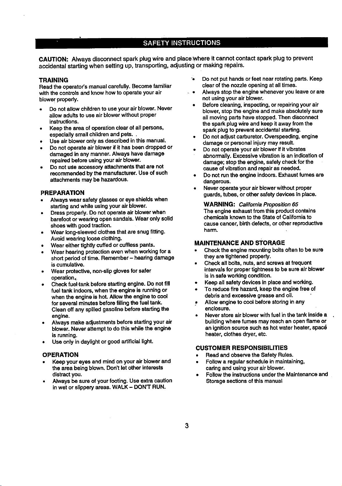
:lead these instructionsandthe operatingmanual initsentirety_beforeyou attemptto operate your new air blower.
BlowerTube CurvedNozzle Tube
Clamp (_,
ExtensionTube
Cable Guide
Clamp with
Blower
Pleated Tube
Combi-Wrench
_TO][o.]:_,,,."[._o_tl_[.,._
The following items for the operation ofyour blowerare availableat your nearest Searsstore.
• Safety goggles • Airfilter
• Hearing protection • Fuelstabilizer
• Gloves • Sparkplug
• 2-Cycle air cooled engine oil • Gas can
V-!.'%'1_hVd:]lWd
Read these instructionsand the operating manual in
itsentirety before you attempt to assemble or operate
yournew backpack air blower.
Your new backpack air blower has been assembled at
thefactory except for the blowertubes. The necessary
clampsto complete assembly as well as a combination
wrenchare included inthe parts bag enclosedwiththe
unit.
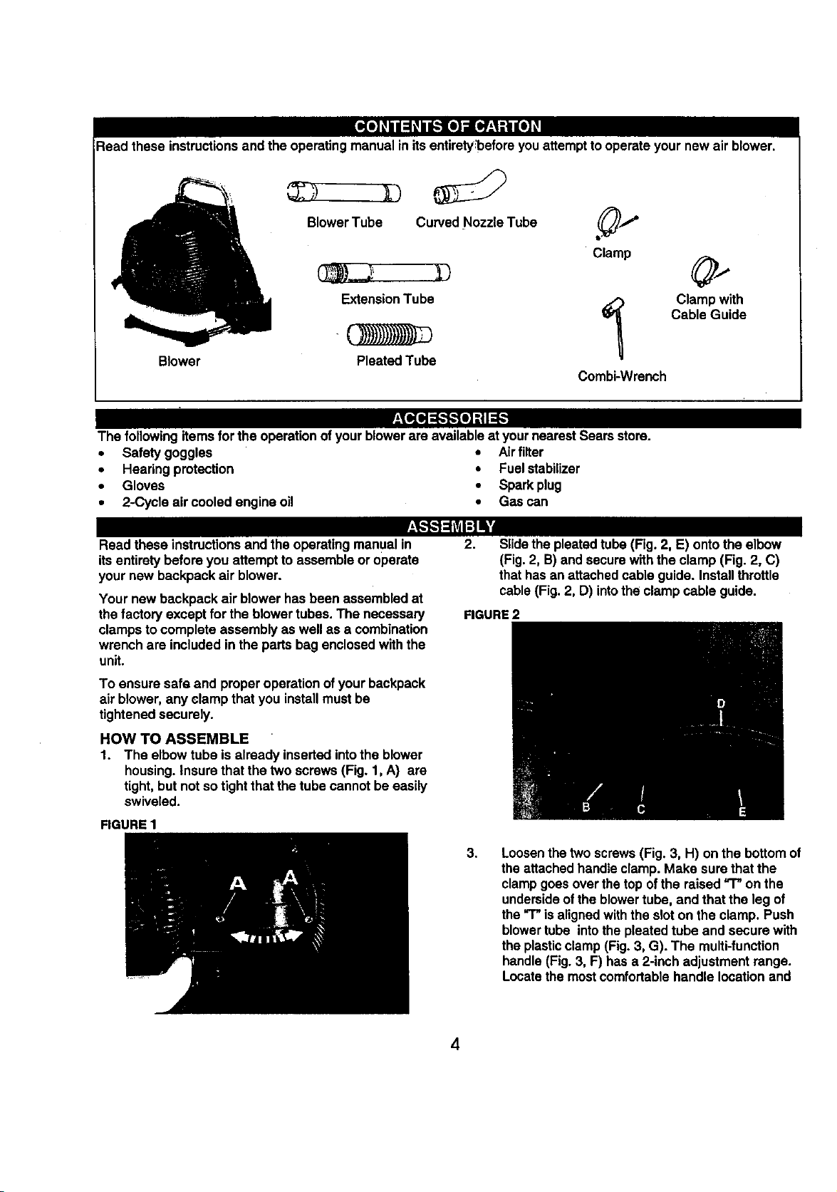
2.
Slidethe pleatedtube (Fig. 2, E) ontothe elbow
(Fig.2, B)and secure withthe clamp (Fig. 2, C)
that hasanattachedcable guide. Installthrottle
cable(Fig. 2, D) intothe clampcable guide.
FIGURE 2
To ensure safe and proper operationof your backpack
air blower,any clamp that you installmustbe
tightenedsecurely.
HOW TO ASSEMBLE
1. The elbow tube is already insertedintothe blower
housing.Insure that the two screws(Fig. 1, A) are
tight,but notso tight that the tube cannot be easily
swiveled.
FIGURE 1
3,
Loosenthe two screws (Fig. 3, H) on the bottomof
theattachedhandleclamp. Make sure thatthe
clampgoes overthe topof the raised_ on the
undersideofthe blowertube, and that the leg of
the"T" isalignedwiththe slot on the clamp. Push
blowertube into the pleated tube and secure with
the plasticclamp(Fig. 3, G). The multi-function
handle(Fig. 3, F) has a 2-inchadjustment range.
Locatethemostcomfortablehandle locationand
4
Page 5
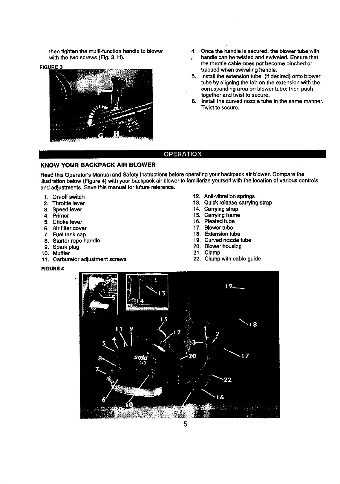
then tighten the multi-functionhandleto blower
with the two screws (Fig. 3, H).
FIGURE 3
KNOW YOUR BACKPACK AIR BLOWER
Read this Operator's Manual and Safety Instructionsbeforeoperatingyour backpackair blower. Compare the
illustrationbelow (Figure4) with yourbackpack airblowertofamiliarize yourselfwith the locationof variouscontrols
and adjustments. Save this manualfor future reference.
1. On-off switch
2. Throttlelever
3. Speed lever
4. Pdmer
5. Choke lever
6. Airfilter cover
7. Fueltank cap
8. Starter rope handle
9. Spark plug
10. Muffler
11. Carburetoradjustment screws
FIGURE 4
4. Once the handle issecured, the blower tubewith
- handle can be twisted and swiveled. Ensure that
thethrottlecable does not become pinchedor
trappedwhen swiveling handle.
.5. Installthe extensiontube (if desired) ontoblower
tube by aligningthe tab on the extensionwiththe
correspondingarea on blower tube; then push
togetherand twist to secure.
6. Installthe curvednozzle tube in the same manner.
Twistto secure.
12. Anti-vibrationsprings
13. Quickrelease carryingstrep
14. Carryingstrap
15. Carryingfreme
16. Pleated tube
17. Blowertube
18. Extensiontube
19. Curved nozzletube
20. Blowerhousing
21. Clamp
22. Clampwithcable guide
5
Page 6

HOW TO USE YOUR BACKPACK AIR
BLOWER
GASOUNE AND OIL MIXTURE
Important! Do not use automotiveor boatoils in
yourair blower. These oilsdo nothave proper
additivesfor 2-cycle, air-cooled enginesand can
cause engine damage.
The 2.cycle engine onthis productrequiresa fuel
mixtureof regularunleaded gasolineand a highquality
2-cycleair-cooled engine oilfor lubricationofthe
bearingsand other movingpads.The correctfuel:oil
mixtureis 40-1 (see Fuel MixtureChad). Too littleoil
or the incorrectoil type will cause poorperformance
and may cause the engine to overheatand seize.
Gasoline and oil must be premixedina clean
approvedfuel container.Alwaysuse fresh regular
unleadedgasoline. This engine iscertifiedto operate
on unleaded'gasoline.
I
FUELMIXTURECHART I
GASOLINE OIL
I Gallon 3+2Dunces
2.5Gallons 8.0Dunces
IMPORTANTI Alcoholblendedfuelscalledgasohol
(usingethanolor methanol)can attract moisture,
whichleads to oil/gas separation andformationof
acidsduringstorage. Acidicgas can damage thefuel
systemof an engine while in storage.To avoidengine
problems,the fuel systemshouldbe emptied before
storageof 30 days or longer.Drainthe gastank, then
runthe fuel out of the carburetor andfuel linesby
startingthe engine and lettingitrununtilitstops.Usa
fresh fuel nextseason. See storageinstructionsfor
additionalinfot'mation.Never use engineor carburetor
cleaner produc_sinthe fuel tank or permanentdamage
may occur.
2-CYCLE OIL
Craftsman2-cycle, air-cooledengine oilisspecially
blendedwithfuel stabilizers. If you do not usethis
Sears oil,you can add a fuel stabilizer,suchas
CraftsmanNo. 33500, toyourfuel mix.
FUEL STABILIZER
A fuel stabilizerisan acceptablealtamativein
minimizingthe formation of fuel gumdepositsduring
storage. Add stabilizerto gasolinemixtureinfuel
storagecontainer and mix well. Alwaysfollow the fuel
mix ratiofound onthe stabilizercontainer.Run engine
at least5 minutesafter adding stabilizertoallowthe
stabilizerto reach the carburetor.You donot haveto
drain the fuel tank for storage if youare usingfuel
stabilizer.
USING THE MULTI-FUNCTION HANDLE
_Themulti-functionhandlehas an on-off switch (Fig. 5,
A), a throttlelever (Fig. 5, B), and a speed lever (Fig.
5, C). It can be rotated to assure the operator's
•comfort.Once started,the speed lever can be set at a
desired RPM. This frees the operatorfrom holdingthe
throttlelever. If notset on maximumRPM and a
• greater RPM is required, simplysqueeze the throttle
lever. To returnto the lower RPM, release the throttle
lever. If the operator planson blowingat the maximum
RPM for a long periodoftime, the speed lever is
movedtothe =max"setting. Ifthe operator is only
blowingin shortburstsleave the speed lever at the
"min" settingand use the throttlelever to controlthe
speed.
FIGURE 5
STARTING COLD
1. Moveon-off switchto the on positionidentified
withan "1"(Fig. 5).
2. Set speed lever halfway between the =rain" '_
and"max"'_ positions(Fig. 5).
3. Move choke lever (Fig. 6, A) to the =START"
position.
4. Press primer bulb(Fig. 6, B) untilitis halffull and
resistanceis felt.
5. Place lefthand on top of the blower housingnear
carryinghandle. Pullthe starter ropehandle'with
righthandslowlyuntilresistanceisfelt. Then pull
forcefullyand repeatedly until engine attemptsto
start;usually2-3 pulls,no more than 5 pulls.
6. When engine attempts to start, immediately move
choke lever t0 "RUN" posifion.Continue to pull
starterropehandle untilengine starts.
FIGURE 6
6
Page 7

STARTING WARM
Followcold startinginstructionsbutleave choke lever
in"RUN" position.
STOPPING
To stopengine, release thethrottleleverand adjust
the speed leverto "min_position.Moveswitchto
STOP (O) position.In an emergency,immediately
movethe switchto the STOP (O) position.
ADJUSTING THE CARRYING STRAPS
Putthe blower on your back and yourarms through
the carryingstrapsas shown.The back plate of the
blowershouldrestsecurelyagainstyourback. If the
straps need tobe tightened (Fig. 7), pullthe quick
adjustdng ends downwardas needed. If the straps
need tobe loosened,liftthe couplingslocatedat the
bottomof the padded straps.
FIGURE 7
MAINTENANCESCHEDULE
.OWER
Check for loose
fasteners
Clean air filter X
Inspect muffler x
4GINE
Replace spark plug X X
Clean fuel filter X
Clean onglne cooling X X
fins
Clean spark arrestor
screen
X
X
BLOWER
-0
GENERAL RECOMMENDATIONS
The warrantyon thisair blowerdoes notcover items
that have been subjectedto operator abuse or
negligence.To receive fullvalue fromthe warranty,
operatormust,maintainair bloweras instructedin this
manual.
Allitems in the Maintenance sectionofthis manual
shouldbe checkedat least once eachseason.
1,
Service more often whenoperatingin dustyor
dirtyconditions.
2.
Once a year you shouldreplacethe sparkplug
and clean or replace the air filter. A new spark
plug and a clean air filter assure properair-fuel
mixtureand helpyourengine run batter and last
longer.
CHECK FASTENERS
Check all fasteners, includingnuts, bolts,screws and
clamps,to insurethat they are tightand secure. If not,
make all necessary adjustmentspdor to usingair
blower.
CLEAN AIR FILTER
Your engine willnot run properlyand may be damaged
by usinga dirty air filter. Replace air filter element if
deteriorationoccurs.Service more often ifyou use
yourair blowerin very dustyor dirty conditions.
To Clean Air Filter
1. Remove airfiltercover bytuming black knob
counterclockwise.
2. Remove foam air filter.
3. Shake outair filter. If heavily soiled,rinsein a mild
soapand water solution.
4. Dry air fiifercompletelyand oil slightlybyplacinga
smallamountof oil on filterand kneading until
evenly distdbuted.Wipe off excess oil.
5. Reassemble the air filterand cover;ensure that
thefilter is correctlyseated in its slot before
reinstallingcover.
6. Replace air filter element if detedorated.
INSPECT MUFFLER
Inspectmufflerevery25 hoursof use and replace if
corroded.
Page 8

ENGINE
REPLACE SPARK PLUG
Change your spark plugeach year to make your
engine start easy and runbetter.Set spark pluggap at
.020".
CLEAN FUEL FILTER
The fuel filter is located insidethe fuel tank and is
attachedtothe fuel line. To clean, scrub fuel filter
surfacewith a small brush,Replace if deteriorated.
CLEAN ENGINE CYLINDER COOLING FINS
Forbest performance,keep dirt from accumulating
aroundthe enginecoolingfins. Clogged coolingfins
cause the engineto runhotterand shortenengine life.
Coolingfinsmay be cleaned usinga toothbrushor stiff
bristle brush.
CLEAN SPARK ARRESTOR SCREEN (ifinstalled)
Afterevery 25 hoursof usethe spark arrestor screen
mustbe cleaned. Replace screen if detadorating(part
no.2048391).
To clean:
1. Remove the four screws fromthe engine cover.
2. Remove the four screwsfromthe end of the
muffler,
3. Remove the screen and clean with a wire brush.
Replacethe screen if deteriorated.
4. Re-installthe screen and muffler end. Securewith
the fourscrews.
5. Re-installthe engine cover.
CARBURETOR ADJUSTMENT
To complywithemissionregulations,the carburetor
mixtureis pre-set at the factory and can not be
adjustedwithoutpropertools. Any adjustmentmustbe
performedby _ service center.
The idle speed'canbe adjusted.The idlespeed set
screwis located on the top of the unit and to the leftof
thespark plug. It is indicated by the letter=r". To
adjustthe idlespeed, turn clockwiseto increaseand
counterclockwiseto decrease idle speed. Idlespeed is
2100 + 100 RPM.
_n[ol :P,_[_
Prepare yourbackpack air blowerfor storage at the
end of the season or if the unitwill notbe used for 30
daysor more.
BEFORE STORING
1. Use soap and water to wipe down unit.
2. Be sure that all nuts, bolts,screws,and fasteners
are securelyfastened. Inspectfor damaged or
wornparts. Replace if necessary.
BLOWER TUBES
The straightblowertubes can be removed to ease
storage. Use care notto "kink" thethrottlecable.
ENGINE
It isimportantto preventgum depositsfromformingin
essentialfuel system partssuch as the carburetor,fuel
filter, fuel hose, or tank duringstorage.Also, alcohol
blendedfuels, such as gasohol,ethanolor methanol,
can attractmoisture,which leads to separationand
formation of acids duringstorage.Acidicgascan
damage the fuel system of an engine while instorage.
Do notstore gasolinefrom one season tothe next.
Two-cyclemix ages quicklyand can causeengine
damage. Replace your gasolinecontainerif itstarts to
rust.Rustor dirt in yourgasolinewillcause engine
problems.
To avoidengine problems,the fuel systemshouldbe
emptiedbefore storage of 30 daysor more.
Followthese instructions:
1. Drainthe fuel tank.
2. Start engine and let it run untilthe fuel linesand
carburetorare empty. (The engine willstop.)
3. Usefresh gas nextseason.
4. Ifyou use a fuel stabilizer, thegasolinecan be left
inthe tank. CAUTION: Never storeair blower
insidea buildingwithfuel in the tank{ Fumescan
concentrateand possibly reacha source of
ignition. Allow engineto cool before storage.
5. Remove spark plug.
6, Pour a few drops ofoil intothe cylinder.
7. Pull the starter handleslowlyto distributethe oil.
8. Replace spark plug,
STORAGE TIPS
If possible,storeyour unitindoorsand cover itto give
it protectionfrom dust and dirt. Do notuseplastic.
Plasticcannotbreath, which will allowcondensationto
form and will cause yourunitto rust.IMPORTANT:
Never coverair blower whileengine and mufflerare
stillwarm.
8
Page 9

PROB..BJI
Enginesmokese._cessively.
Enginehardtostart,willnot
startorstartsandonlyrunsa
fewseconds.
CAUSE
1. Dirtyairfilter.
2. Fuelmixtureincorrect.
3. Carburetorrequiresmaintenance.
1.Fueltankempty.
2. Engineflooded.
3. Sparkplugnotfiring.
4. Didyairfllten
5. Carburetorrequiresadjuslment.
5.Stalefuelmixorwaterinfuelmix.
7.Sparkplugwire disconnected.
El.SwitchinSTOP(O)posilion.
I
_ON
1.Clean or replaceairfilter.
2. Vedfyyouhave40-1 fuel mixture,
3. ContactSearsSe_ce Center.
1.RII tankwi_ correctfuelmi)_
2.Removeandcleansparkplug;with sparkplug
removedand engineswitchedoff,crankengineafew
timesto removee_cessfuelfromcylinder.Reinstall
sparkplug.
3. Replacesparkplug.
4. Cleanorreplaceair filter.
5. ContactSearsServiceCanter,
6. Draintankandrefillwithfresh,deanfuel mix.
7. Connectwiretoplug.
8, Moveswitchto RUN(I)position.
Enginewill notaccelerate,
!lackspowerordies undera
load.
1. Dirtyairfilter.
2. Sparkplugfouled.
3. Sparkarrestorscreendogged
(ifapplies).
4. Carburetorrequiresmaintenance.
1.Cleanorreplaceairfilter.
2. Cleanorreplacesparkplugand re-gap(.020").
3.Cleanor replacescreen.
4. Contact Sears Service Canter.
9
Page 10

The Celifomia Air Resources Board and Sears are pleased to explain the
eadssisn control system warranty on your t 996 and later lawn and garden
equipment engine. In California, now lawn and garden equipment engines
m_sl be des_jned, builf, and equipped to meet the state's stringent anli-smog
standards. Sears must warrant the emission contrdisystem on your lawn and
garden equipment engine for the period of time listed below provided there
has been no abuse, neglect, or Improper maintenance of your lawn and
garden equipment engine.
Your emission control system includes parts such as the caYouratororfuel
injected system, the ignition system, and connectors end other emlaelon-
mlatnd a_;sembllas.
Where a warrantable condition exists, Sears will repair your lawn and garden
equipment engine at no cost to you including diagnosis, parts, and labe_
MANUFACTURER'S WARRANTY COVERAGE:
"n_e1996 and later lawn and garden equipment engines are warranted fur two
years. If any emiselon-relatod pan on your engine isdefective, the partwill be
repaired or replaced by Sears.
OWNER'S WARRANTY RESPONSIBILITIES:
AS the lawn and garden equipment engthe owner, you are responelb_ forthe
performance of the required maintenance listed in your Operator's Manuel.
Sears recommend_ that you retain all receipts covedeg maintenance on your
lawn and g_d__ engine. Seem cannot deny warranty solely for the
leek of recelpta o_ tor your fultom to ensure the perfomlance of ell sshedulnd
maintenance.
ASthe lawn and garden equipment eugine owner, you should howiNer be
aware that Sears may deny you warranty coverage If your lawn and garden
equipment engine or a part has failed due to abuse, neglect, ir_oropar
maintenance or unapproved moddicat_es.
You are responsible for pmsendng your lawn and garden equipment engine to
a Sears mpelr center as soon as a problem exists. 1he warranty repelm
should be completed in a reasonable amount of _me, not to exceed 30 days.
If you have any questions regarding your warranty dghbl and respon_"o4T_es,
you should contact Sears at 1-800-473-7247.
A. WARRANTY COMMENCEMENT DATE
The warranty pe_od begins on the date the equipment is purchased by
a reta}l customei_
B,
LENGTH OF WARRANTY COVERAGE
Sears warrants tothe initial owner and each subsequent purchaser that
the engine is free from defects in matehals and wedananship for a
period of two years from date of odgfoel purchase from Sears.
C.
WHAT iS COVERED
1. REPAIR OR REPLACEMENT OF PARTS
Raper or replacement of any warranted part will be pedormed at
no cberge to the owner at a warranty station. To locate a
warranty station, you may call Sears it 1-800-473-7247, (24
hours, 7 days I week).
2. WARRANTY PERIOD
Any warranted bert which Is-not scheduled for rep_cement as
required rnalntenance, or which isscheduled only for regular
inspactfon to the effect of *repair or replace as necdssa_" shall
be warranted forthe warranty pedod. Any warranted part which is
scheduled for replacement as required maintenance shall be
warranted for the pedod of time up to the first scheduled
reqlacement point for thatpart.
3. DIAGNOSIS
The owner shall _ be charged for diagnostic labor, w_ibh leads
to the determination that a warranted pan la defective, if the
diagnostic work Is performed it Sears.
4. CONSEQUENTIALDAMAGES
'i
The engine manufacturer is liable fordamages to the engine
components caused by the failure of a warranted part still under
warranty.
WHAT IS NOT COVERED
1. Failures caused by abuse, ne_ect, o_Improper maintenance.
2. ACid-onor mod'dindparts. The use of add-on or mod_lfed parts can
be groundsfor disallowing a warranty claim. The engine
manufacturer is not liable to cover failures of warranted parts
caused by the use of add-on or modified parts.
3. Any indirect or cc_.sequentild damages that may result from the
lailum or malfunction of the Sears product. S_ne states do not
allowthe exclusion or limitation of consequential damages so
these limitations may not apply to you.
4. Normal sen'ice requirements adelng dudng the warranty period
suchas carburetor or ignition adjustment, cleablug, nonnst wea¢.
lubrication, spark plugs, lfhars, starter ropes, etc.
5. Normal service work over and above the repair or replacement of
defectivepads.
6. Any failure that results from an accident, customer abuse, noanof
wear, neglect or failure to operate the product in accordance with
the insm._-tlads provided in the Operators Manual or provided
with the prnduct,
7. Pre-delfvePjset-up time.
8. Operslfon of an engine with an lacomlot fuel:o_ ratfo, air filter
removed or speeds in excess of Sears' recommendaUons
ap_icaMa).
9. Transportationcosts assoclatnd with dalivedug and ratum of
productto a Sears warranty station.
E.
HOW TO FILE A CLAIM
Warranty claims may be submitted on several c_ffemntforrr_:
Sears Warranty Claim Request
Outdoor Power Equipment Institute
UniversalWarranty Claim Report
En_ne Service AssoctalfonClaim
Warranty claims must be received at Sears within 60 days of the date
of repair noted on the delm.
F°
WHERE TO GET WARRANTY SERVICE
Warranty eawine or repairs shall be provided at Sears Sewi,.'_ Centers.
Forthe address of a Service Center near you call Sears at 1-800-473-
7247, {24 hours. 7 days a week).
G.
MAINTENANCE, REPLACEMENT AND REPAIR OF EMISSION
RELATED PARTS
Sears replacement parts must ha used in the pedoanance of any
warranty maintenance or repairs on emlaelen-mlatnd parts and will be
providedwithout charge during the warranty pedod.
H.
EMISSION CONTROL WARRANTY PARTS LIST
Seam' warranty incfudes the fo_owing parts (ubless said part was
scheduled for tenement as required maintenance): Air FlfteL,Fuel
Rltor. Carburetorand internal parts, Choke Mechanism, Intake
Manifold, Spark Plug, Flywheel. ign_on Mndute.
MAINTENANCE STATEMENTS
Follownormal maintenance set.Ace, recommended fuel mixl_m (whom
applicable), lubdcatlan, operation and storage of the product as
explained in the Oparatc_'s Manual. The owner shall not be charged for
diugnoslfc labor, which leads to the determination that a warranted dart
isdefective, if the diagnostic work is performed at Sears.
I0
Page 11

_, 140
146
--155
--156
--157
135
/
125
///
/
/ f
_15o
74
F----95
I I
21
20
Page 12

Pos.-No.Ord,er..No.
1 )018346
2 )016428
5 )020104
6 )034135
10 2300 774
11 2074294
12 :)054220
13 _050102
14 _31375
15 2200249
17 0075101
18 0052226
20 0018340
21 0072140
22 8033358
25 2100629
26 2063334
31 2280248
33 2031 117P
34 0055207"
40 2011802
41 2500 732
42 0018348
43 8021 256
44 4063160
45 2300730
47 0018363
48 0072144
49 2074562
50 25O0731
51 )028100
52 1072143
53 _061510
54 )018421
57 )084600
58 3073385
59 2380783
50 Z380773
(57) :)084600
(58) _073385
259) Z3O0783
6 _072148
63 0018327
70 2061512
71 0018337
72 2074916
73 8021235
74 2061 515
75 2380805
80 0064407
81 0064436
82 2700322
85 0062321
86 8062325
87 2074917
88 0010107
90 0062263
91 2074914
95 2800566
180 6880286
101
(1_ 68800286
(103)8055279
(104)8069721
screw
activator
nut
cltcfip
fl_heel
sleeve
oilseal
ballbearing
washer
crankshaft
springwasher
needlebearing
screw
springwasher
spacertubu
crankcase,compi.
pistonpin
pistonpindrdip
cylinder
flap
screw
nut
saal
sparkping
screw
tendonwasher
insulator
muffler
nut
tendonwasher
exhaustgasket
screw
sparkplugcap
contactslxing
ignitioncoil
ignitioncoil,compl.,incl.
sparkplugcap
contactspring
ignitioncoil
washer
screw
manifoldgasket
screw
manifold
nut
carburetorgasket
hose
hose
nng
nng
suctionflange
screw
nng
chokeflap
throttlecable
s_c'w
exhaustcover,incl.
screw
safetydng
decal
Po_-N_
7
"102
103
104
105
106
107
108
110
111
120
121
122
125
126
128
129
130
"135
137
138
140
142
145
146
147
150
155
156
157
Order-No.
4048380
8055279
8069721
40736790GN
8018363
0069168
8069716
2073503
8018363
4073676DGN
8018363
0018342
2042667
8018362
0015155
0033393
4061908
4480241
8034135
8020104
4073677DGN
8020101
4036415
4042800
0018362
0080580
0510949
0510975
0510976
:_uantity
1
1
1
1
4
1
1
1
3
1
12
1
1
1
_p_on
filterplate
safetyring
decal
enginecover
screw
decal
decal
airguide
Screw
blowerhousing1
screw
screw
dampingplate
screw
screw
spacer
airfiltergasket
fanwheoi
drclip
nut
blowerhousing2
nut
_rotedinnscreen
supportplate
mew
comblwrench
_ket-kit-carburetor
repair-_-carburetor
throttleaxlekit<ahoretor
12
Page 13

MODELNUMBER360.796900
I
2
1
Pox'No,_er-No. I quantit 3escdption
1 )01825711 s_ew
2 )01833812 so'ew
5 !I00 58311 starterhousing
8 )06319511 start_rope
9 ZO745691I startergrip
12 Z6O028411 springcassette
13 Z07491511 ropepulley
15 ZO7434311 staderpawl
16 _0316111 washer
17 20749771 template
18 Z0319651 spacer
19 O0733651 pin
20 00341261 slxingwasher
21 DO105191 screw
22 D0341521 drdip
25 26O0293| starter,compl.
13
Page 14

MODEL NUMBER 360.796900
25
Po_-No.
1
2
5
(7)
(8)
(9)
(lo)
(11)
(12)
7
8
9
10
11
12
15
16
18
20
21
25
_der,No,I Quantity
4073682I 1
_01836312
Z700409I I
1071272 I 1
D067114I 1
0073351 I 1
6063328 I 1
O073_52 I 1
2700327 I I
4071272 I 1
0067114 I 1
0073351 I 1
6063328 I 1
0073352 I '1
2700327 I 1
O061280I 1
27O0395I 1
0018274|2
0064435 I 1
0064300 I 1
4O35904I 1
Description
ho_omplate
5_ew
fueltank,incl.:
fueltank
socket
r_et
_el pidc-up
fueltank
so_et
el
_mmet
I pi_-up
lidgasket
tanEcap,compl.
screw
hose
hose
carr/ingframe
30 4042577
31 0073396
32 6043107
33 0018363
35 4046100
40 0018363
41 4074126
42 4074275
45 4073680
46 4074962
48 0098147
50 0018369
55 4074921
56 43O0355
57 4074412
60 43O0332
(55) 4074921
(56) 43O0335
(57) 4074412
61 0018370
_nt_
2
4
4
8
2
2
2
2
1
5
1
1
2
2
2
2
2
2
De_ription
tensi_plate
avspnng
flangeplate
screw
tensionbracket
screw
cap
strapholder
ba_plate
cushionrivet
backcushion
scmw
strapclamp
shoulderstrap
strapholder,black
shoulder_ap,inc.:
strapclamp
shoulderstrap
strapholder,black
screw
14
Page 15

MODEL NUMBER 360.796900
Operator's
Manual
40
10
11
1
2
I_.-No.
Order-No. _antity Description
1
4071289 1 curvednozzletube
2
4071288 1 extensiontube2
5
4400248 I _tmvertube1
7
0066399 I damp,compL
4071148 deatedtube
8
10
0066130 clampwithcableguide
11
0018257 sere,.,'
15
4073124 elbowtube
0020101 nut
2O
22
48O0222 griphalfleft,compL
25
O073408 spdng
26
4073673 throttlelever
27
O035159 washer
30
4074938 outergriphalf
33
0018356 screw
34
0018357 screw
00644151 hose
35
36
0084477 on..offswitch
37
28(30566 throttlecable
O084855 on-offcable
39
4o
I_47OlO_ Operatur'sManual
15
Page 16

 Loading...