

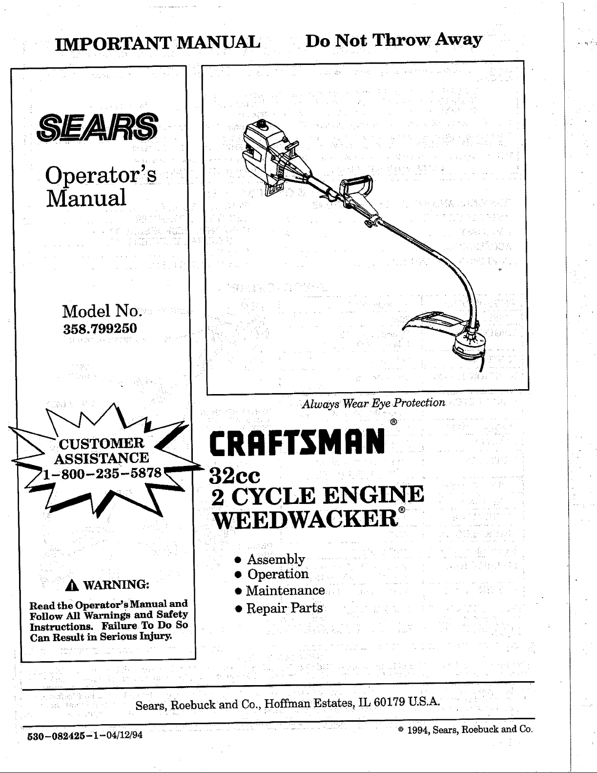
IMPORTANT MANUAL Do Not Throw Away
Operator,s
Manual
Model No,
358.799250
ASSISTANCE
WARNING:
Read the Operator' s Manual and
Follow All Warnings and Safety
Instructions. Failure To Do So
Can Result in Serious Injury.
Always Wear Eye Protection
®
CRRFTSMRN
32cc
2 CYCLE ENGINE
WEEDWAC ER
• Assembly
• Operation
• Maintenance
• Repair Parts
530-082425" 1- 04/12/94
Sears, Roebuck and Co., Hoffman Estates_ IL 60179 U.S.A.
1994, Sears, Roebuck and Co.
ONEYEARLIMITED WARRANTY ON CRAFTSMAN GAS-POWERED WEEDWACKER®
When this Cr.aftsman Gas.-Powered Weedwacker is maintained, lubricated, and tuned up according to the operating and
mmntenance instructions m the operator's manual, Sears will repair, free of charge, any defect in materials orworkmanship
as IOltOWS:
1 YEAR - Parts and Labor, when used for household purposes.
90 DAYS - Parts and Labor, if used for commercial, institutional, or professional purposes.
30 DAYS - Parts and Labor, if used for rental purposes.
This warranty excludes nylon line, spark plug, and air filter, which are, expendable parts and become worn during normal use.
This warranty applies only while this product is in use in the United States. WARRANTY SERVICE IS AVAILABLE BY RETURNING THE
WEEDWACKER TO THE NEAREST SEARS SERVICE CENTER/DEPARTMENT IN THE UNITED STATES.
This warranty gives you specific legal rights, and you may also have other rights which vary from state to state.
SEARS, ROEBUCK AND CO. DEPT. 817WA HOFFMA1N ESTATES, EL 60179
TABLE OFCONTENTS
WARNINGS AND SAFETY INSTRUCTIONS ... 3
KNOW YOUR UNIT ........................... 5
ASSEMBLY .................................. 6
ACCESSORIES .............................. 8
/ FUELING YOUR ENGINE ...................... 9
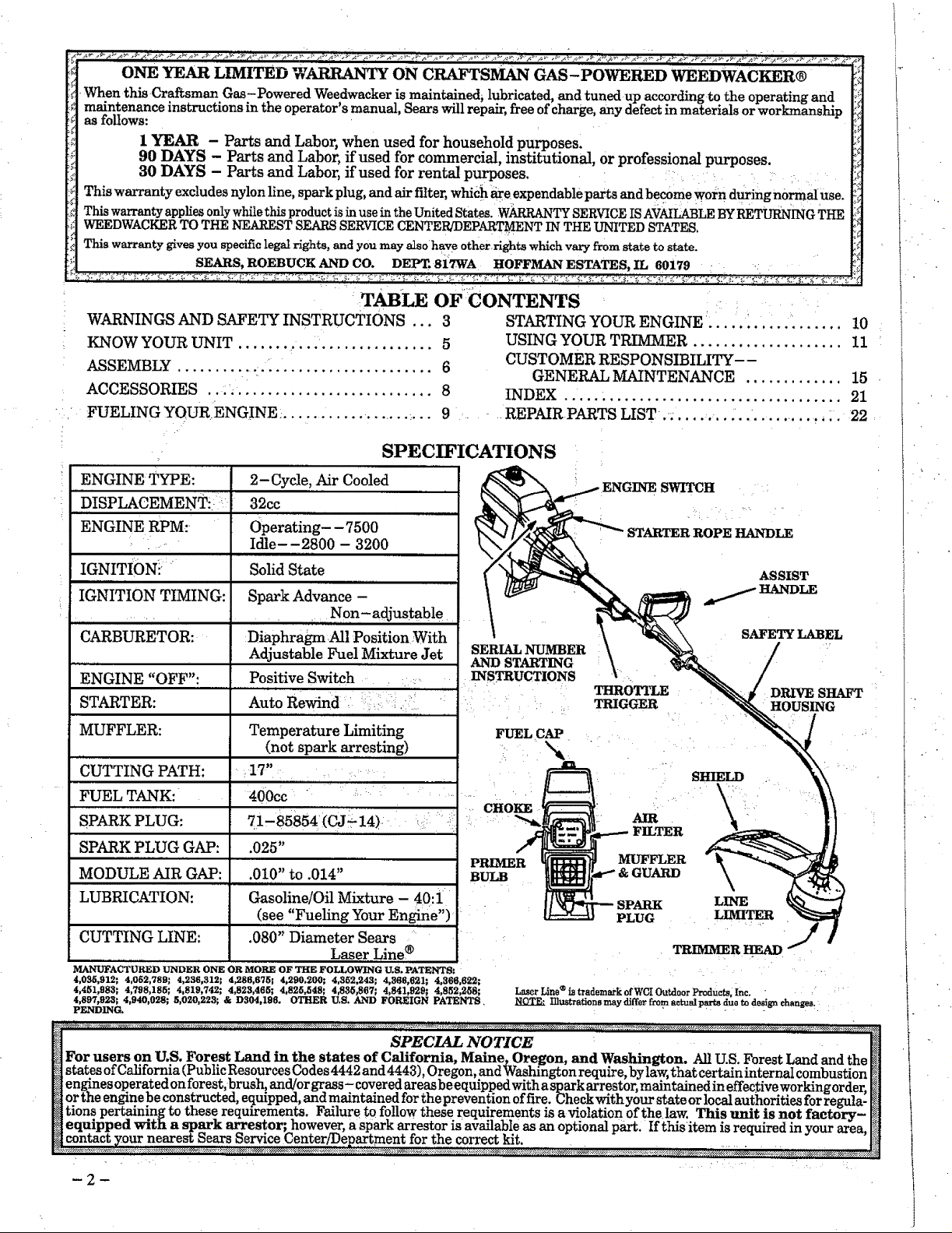
SPEC_ICATIONS
: ENGINE TYPE:
"DISPLACEMENTi _
: 11 ,
ENGINE RPM:
IGNITION: "
IGNITION TIMING:
CARBURETOR:
=,Lilt ,
ENGINE "OFF":
STARTER:
MUFFLER:
CUTTING PATH:
FUEL TANK:
SPARK PLUG:
SPARK PLUG GAP:
MODULE AIR GAP:
LUBRICATION:
CUTTING LINE:
MANUPACTURED UNDER ONE OR MORE OF THE FOLLOWING U.S. PATENTS:
4,035,912; 4,052,789; 4.236,312; 4_86,675; 4,290,200; 4,352,243; 4,366,621; 4,366,622;
4,4_;1,983; 4,798,185; 4,819,742; 4,823,465; 4,825,548; 4,835,867; 4,841,929; 4,852,258;
4,89%923; 4,940,028; 5,020,223; & D304,196. OTHER U.S. AND FOREIGN PATENTS,
PENDING.
2-Cycle, Air Cooled
32cc
Operating- -7500
Idle--2800 - 3200
, ,
Solid State
Spark Advance -
Non-adjustable
" ,r, r,
Diaphragm All Position :With
Adjustable Fuel Mixture Jet
....pos!tive Switch •
Auto Rewind - :::: :i.?i
Temperature Limiting
(not spark arresting)
17"
4oocc ' ' '.... '.....
.025"
.010" to .014"
..,.Hi, .., ,
Gasoline/Oil Mixture - 40:i
(see.',iFueling Your Engine")
.080" Diameter Sears ....
Laser Line ®
STARTING YOUR ENGINE .................. 10
USING YOUR TRIMMER .................... 11
CUSTOMER RESPONSIBILITY--
GENERAL MAINTENANCE ............. 15
INDEX ..................................... 21
REPAIRPARTS LIST. ........... ........... :. 22
SWITCH
ASSIST
SAFETY LABEL
SERIAL NUMBER
AND STARTING
INSTRUCTIONS
THROTTLE
TRIGGER
DRIVE SHAFT
HOUSING
FUEL CAP
SHIELD
\
AIR
FILTER
MUFFLER
GUARD
LINE
PLUG LIMITER
• TRIMMERHEAD
®
LaserLine istrademarkofWCI OutdoorProdUcts,Inc. / :_'
NOTE.. lllustrationemay differfrom aotualpro't8duo to designehangesr
i-
SPECIAL NOTICE ............
For users on U.S. Forest Land in the states of California, Maine, Oregon, and Washington. All U.S. Forest Land and the _]
states of California (Public Resources Codes 4442 and 4443),Oregon, and Washington require,bylaw,that certain internal combustion N
engines operated on forest, brush, and/or grass-covered areas beequipped with a sparkarrestor, maintained ineffectiveworking order,_]
orthe engine be constructed, equipped,and maintained for the prevention offire Checkwithyour state orlocal authorities forre la-
i ...... " ..... gu
tons pertaining to these reqmrements. Failure to follow these r_eqmrementsm awolatmn ofthe law. This unit ISnot factory- I_
equipped with a spark arrestor; however, a spark arrestor is available as an optional part. Ifthisitem is required in your area, I_
v _1_, nearest Sears Service Center!Department for the correct kit. [!_]
_2--
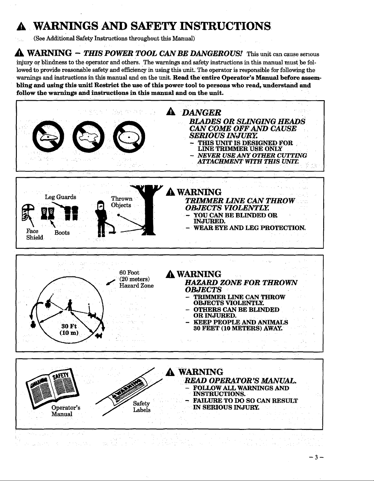
A WARNINGS AND SAFE INSTRUCTIONS
(See Additional Safety Instructions throughout this Manual)
A WARNING - THIS POWER TOOL CAN BE DANGEROUS! This unit can cause serious
injury or blindness to the operator and others. The warnings and safety instructions in this manual must be fol-
lowed to provide reasonable safety and efficiency in using this unit. The operator is responsible for following the
warnings and instructions in this manual and on the unit. Read the: entire Operator's Manual before assem-
bling and using thisunit! Restrict the use of this power tool to persons who read, understand and
follow the warnings and instructions in this manual and on the unit.
A
DANGER
BLADES OR SLINGING HEADS
CAN COME OFFAND CAUSE
SERIOUS INJURY.
- THIS UNIT IS DESIGNED FOR
LINE TRIMMER USE ONLY
- NEVER USE ANY OTHER CUTTING
ATTACHMENT WITH THIS UNIT.
_k WARNING
Leg Guards Thrown
.WW
_Fa:c '_f O_bjects
e Boots
Shield
TRIMMER LINE CAN THROW
OBJECTS VIOLENTLY.
- YOU CAN BE BLINDED OR
INJURED.
- WEAR EYE AND LEG PRO_CTION.
Operator's
Manual
60 Foot
(20 meters)
f Hazard Zone
Safety
Labels
AkWARNING
HAZARD ZONE FOR THROWN
OBJECTS
- TRIMMER LINE CAN THROW
OBJECTS _OLENTLY.
- OTHERS CAN BE BLINDED
OR INJURED.
- KEEP PEOPLE AND ANIMALS
30 FEET (10 METERS) AWAY.
A WARNING
READ OPERATOR'S MANUAL.
- FOLLOW ALL WARNINGS AND
INSTRUCTIONS.
- FAILURE TO DO SO CAN RESULT
IN SERIOUS INJURY.
WARNINGS AND SAFETY INSTRUCTIONS..,.(Continued)
Ak OPERATOR SAFETY
o
Always wear safety eye protection.
o
Always wear long pants, long sleeves, boots and
gloves: Wearing safety leg guards is recom-
mended. Do not go barefoot or wear sandals, jew-
elry, short pants, short sleeves, loose clothing, or
clothing with loosely hanging ties, straps, tassels,
etc.; they can be caught in moving parts.
o
Secure hair so it is above shoulder length.
o
Do not operate this unit when you are tired, ill, or
under the influence of alcohol, drugs, or medica-
tion.
o
Wear_hearingprotectionifyou use thisunit for
more than 1-1/2hours per day.
Never startorrun theengineinsideadosed room
orbuilding.Breathingexhaustfumes can kill.
Keep handlesfreeofoiland fuel.
UNIT/MAINTENANCE SAFETY
A
@
Look for and replace damaged or loose parts be-
fore each use. Look for and repair fuel leaks before
use. Keep the unit in good working condition.
Replac e trimmer head parts that are chipped,
cracked, broken, or damage in any other way be-
fore using the unit.
Use only .080" diameter SEARS Laser Line.
Never use wire, rope, string, etc.
Make sure the unit is assembled correctly as listed
in this manual.
Make carburetor adjustments with the lower end
supported to prevent the trimmer line from con-
tacting any object.
Keep others away when making carburetor ad-
justments.
Disconnect the spark plug before performing
maintenance except carburetor adjustments.
Use only genuine SEARS accessories and replace-
ment parts as recommended for this unit.
A FUEL SAFETY
• Mix and pour fuel outdoors.
• Keep away from sparks or flames.
• Use a container approved for fuel.
• Do not smoke or allow smoking near fuel or the
unit or while using the unit.
' Wipe up all fuel spills before starting engine.
• Move at least 10 feet (3 meters) away from fueling
site before starting engine.
• Stop engine and allowthe engine to cool before re-
moving fuelcap.
• Empty thefueltank beforestoringtheunit.Use
up fuelleftinthe carburetorby startingtheen-
gineand lettingtheenginerun untilitstops.
• Storeunitand fuelin an _areawhere fuelvapors
cannotreachsparksor open flamesfrom water
heaters,electricmotorsorswitches,furnaces,etc.
Ak CUTTING SAFETY
• Inspect the area to be cut before each use. Remove
objects (rocks, broken glass, nails, wire, string,
etc.) which can be thrown or become entangled in
the trimmer head. x
• Keep others including children, animals, bystand-
ers and l_elpers outside the 60 foot (20 meter) Haz-
ard Zone. Stop the engine immediately if you are
approached. •....
• Always keeptheengineon theright-handsideOf
yourbody.
- Hold theunitfn_nlywithbothhands.
• iKeep firm footingand balance.Do not over-
ireach.
• _Keep thetrimmer head belowwaistlevel.
•, Do notraisetheengineaboveyourwaist.
•'Keep allpartsofyour body away from trimmer
head and mufflerwhen engineisrunning.
• _Cut fromyour righttoyourleft.
• Use onlyforjobsexplainedinthismanual.
A TRANSPORTING AND STORAGE
• Stop the unit before transporting.
• Keep the muffler away from your body.
• Allow the engine to cool, and secure the unit be-
fore storing or transporting in a vehicle.
• Empty the fuel tank before storing or transport-
ing the unit. Use up fuel left in the carburetor by
starting the engine and letting the engine run un-
til it stops.
• Store unit and fuel in an area where fuel vapors
cannot reach sparks or open flames from water
heaters, electric motors or switches, furnaces, etc.
• Store unit so line limiter cannot accidentally
cause injury. The unit can be hung by the bracket
below the engine or by drive shaft housing.
• Store the unit out of the reach of children.
If situations occur which are not covered in this manual, use care and good judgment.
If you need assistance, contact your SEARS Service Center/Department or the
CUSTOMER ASSISTANCE HOTLINE, 1-800-235-5878.
H Exp_suret_vibrati_nsthr__ghpr___ngeduse_fgas__inep_weredhandt___sc_uldcauseb___dvesse__rnerve H
damage in the f'mgers, hands, and wrists of people prone to circulation disorders or abnormal swellings. Pro-
m longed use in cold weather has been linked to blood vessel d.amage in otherwise healthy people. If symptoms M
occur such as numbness, pain, loss of strength, change in skin color or texture, or loss of feeling in the _gers,
H hands or wrists, discontinue the use of this tool and seek medical attention. An anti-vibration system does not _1
l_] guarantee the avoidance of these problems. Users who operate power tools on a continual and regular basis [_
__r doo_.se...lythe.._..._physiooooooo__.c_co_.diti0_noo_sndthe con&'tion o f_ tool......................................_,_
4
iii I _lJil I i
i /i _lil •
KNOW YOUR UNIT
i J iiiiii l illi i iiii
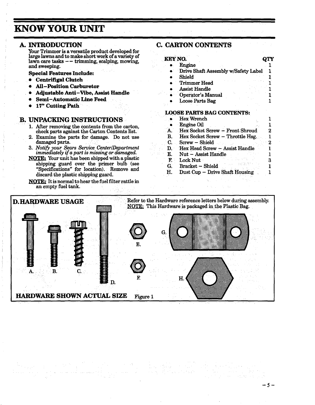
A. INTRODUCTION C. CARTON CONTENTS
Your Trimmer is a versatile product developed for
large lawns and to make short work of a variety of
lawn care tasks -- trimming, scalping, mowing, KEY NO.
and sweeping. • Engine
Special Features Include:
• Centrifigal Clutch
• All-Position Carbmtor
• Adjustable Anti-Vibe, Assist Handle
• Semi-Automatic Line Feed
• 17" Cutting Path
B. UNPACKING INSTRUCTIONS
1. After removing the contents from the carton,
check parts _nst the Carton Contents list.:
2. Examine the parts for damage . Do not use
damaged parts ....
3. Notify your Sears Service Center/Department
immediately if apart is missing or damaged.
Your unit has been shipped witha plastic
shipping guard over the primer bulb (see
"Specifications" for location). Remove and
discard the plastic shipping guard.
_ It is normal to hear the fuel filter rattle in
anempty fuel tank.
• Drive Shaft Assembly w/Safety Label 1
• Shield ]
• Trimmer Head 1
• Assist Handle 1
• Operator's Manual 1
• Loose Parts Bag 1
LOOSE PARTS BAG CONTENTS:
• Hex Wrench 1
• Engine Oil 1
A. Hex Socket Screw - Front Shroud 2
B. Hex Socket Screw - Throttle Hsg. 1
C. Screw- Shield 2
D. Hex Head Screw - Assist Handle 1
E. Nut - Assist Handle 1
F. Lock Nut 3
G. Bracket- Shield 1
H. Dust Cup - Drive Shaft Housing 1
QTY
1
D. HARDWARE USAGE
. ;
HARDWARE SHOWN ACTUAL SIZE
L . •
: Refer to the Hardware reference letters below during assembly.
This Hardware is packaged in the Plastic Bag.
G.
E_
@
H.
Figure 1
H
ASSEMBLY
(If tool is received assembled, repeat all steps in this section to be sure assembly is correct and is ad _+
justed for the operator.) -
A. PREPARATION
This Operator's Manual is designed to help you as.
semble the tool and to provide its safe operation. It is
-importantthat you read the entire manual to become
familiar with the tool before you begin assembly or
call our CUSTOMER ASSISTANCE HOTLINE at
1"800-235-5878.
iii
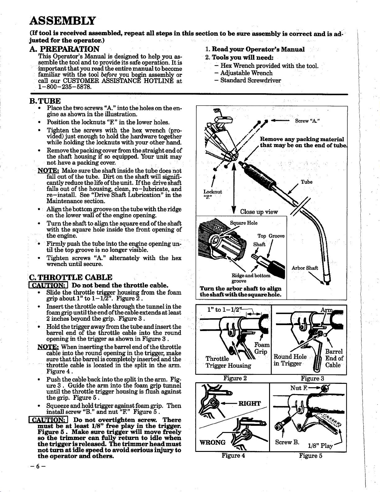
B.T_E
• Place the two screws "A." into the holes on the en-
gine asshown in theillustration.
• Positionthelocknuts"E" inthelowerholes.
• Tighten the screws with the hex wrench (pro-
vided)justenough toholdthehardware together
whileholdingthelocknutswithyourotherhand.
• Remove thepackingcoverfromthestraightendof
the shafthousingifsoequipped.Your unit may
not have a packing cover.
Make sure the shaft inside the tube does not
fall out of the tube. Dirt on the shaft will signifi-
cantly reduce the life of the unit. If the drive shaft
falls out of the housing, clean, re-lubricate, and
re-install. See "Drive Shaft Lubrication" in the
Maintenance section.
• Align the bottom groove on the tube with the ridge
on the lower wall of the engine opening.
• Turn the shaft to align the square end of the shaft
with the square hole inside the front opening of
....the engine.
'• Firmlypush thetube intotheengineopeningun-....
tfl the top groove is no longer visible. • •
• Tighten screws "A." alternately with the hex
wrench until secure.
IC. THROTTLE CABLE
__ Do not bend the throttlecable.
• Slidethethrottletriggerhousing from the foam
gripabout1" to 1-1/2". Figure2.
' • Insertthethrottlecablethroughthetunnelinthe
foam gripuntiltheend ofthecableextendsatleast
2 inches beyond the grip. Figure 3,
• Hold the trigger awayfrom thetube and insert the
barrel end of the throttle cable into the round
opening in the trigger as shown in Figure 3.
When inserting the barrel end of the throttle
cable into the roundopening in the trigger, make
sure that the barrel is completely inserted and the
.... throttle cable is located in the split in the arm.
Figure 4.
• Push the cable back into the split in the arm. Fig-
ure 3. Guide the arm into the foam grip tunnel
until the throttle trigger housing is flush against
the grip. Figure 5.
• Squeeze and hold trigger against foam grip. Then
install screw B. and nut E Figure 5.
Do not overtighten screw. .There
must be at least 1/8" free play in the trigger.
Figure 5. Make sure trigger will move freely
so the _er can fully re .turn to idle when
the trigger is released. The trimmer head must
not turn at idle speed to avoid serious i_ury to
the operator and others.
•6
1. Read your Operator's Manual
2. Tools you will need:
- Hex Wrench provided with the tool.
- AdjustableWrench '
- StandardScrewdriver
Remove any packing material
may be on the end of tube
Locknut
I: Close up view
Hole
Top Groove
Ridgeandbotton
groove
Turn the ar.bor shaft to align
the shaftwiththe square hole.
1"toI-]
Throttle
Trigger Housing
Round Hole _
inTrigger i
Figure 2
RIGHT
WRONG
Screw B.
Figure 4
, :
Tube
ArborShaft
B_arrel
End of
Cable
Figure 3
Nut
1/8"
Fig_e 5
t
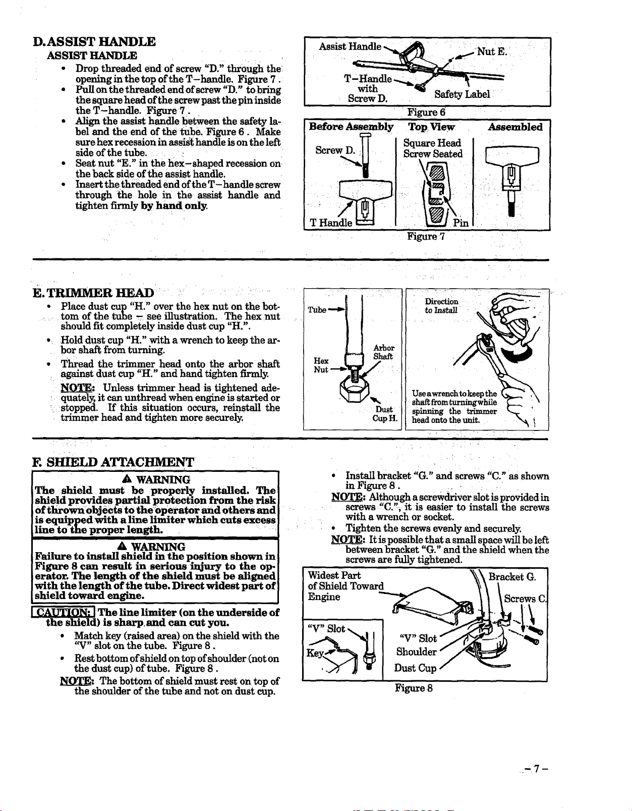
D.AS SIST HANDLE
ASSIST HANDLE
• Drop threaded end of screw "D.'; through the
opening in the top of the T-handle. Figure 7.
• Pull on the threaded end ofscrew"D." to bring
the square head of the screw past the pin inside
the T-handle. Figure 7.
• Align the assist handle between the safety la-
bel and the end of the :tube, Figure 6. Make
sure hex recession in assist handle is on the left
side of the tube ..........
• Seat nut "E." in thehex,shaped recession on
the back side of the assist handle.
• Insert thethreaded end of the T- handle screw
through the hole in the assist handle and
tighten fn_rdy by hand only.
! !•• -
Figure 6
Befm'e Assembly Top, View , '_emhled
. , L.__.2.t in ,,
Figure 7
illll
E.TRIMMER HEAD __- i_
• Place dust cup "H." over the hex nut on the bot-
....... tom of the tube -see illustration. The hex nut
should fit completely inside dust cup "H.".
•: Hold dust cup "H." with a wrench to keep the ar-
bor shaft from t_arning.
• Thread the trimmer head onto the arbor shaft
=_age_st dust cup "H." and hand tighten fnm_ly.
_: Unless trimmer head is tightened ade-
quately, it can unthread when engine is started or
': ;stopped. If this situation occurs, reinstall the
trimmer head and tighten more securely.
i ill,
E SHIELD ATTACHMENT
A WARNING
The shield must be properly installed. The
shield provides partml protection from the risk
of t]iro_obj_cts to theoperator and:others and
is eqmpped with a line limiter which cuts excess : ....
line to the proper length. : • _ .......
mii imiil I IIHIIIIIIIIIIIII illlliH iil i
A WARNING
F_lure to install shield inthe position shown in
Figure 8can result in semous injury to the op-
erator. The length of the shield must be aligned
with the length of the tube. Direct widest part of
shield toward engine.
the shield) is sh_.and can cut you.
• Match key (raised area) on the shield with the
• Rest bottom of shield ontop of shoulder (not on
NOTE: The bottom of shield must rest on top of
The line limiter (on the underside of
"V" slot on the tube. Figure 8.
the dust cup) of tube. Figure 8.
the shoulder of the tube and not on dust cup.
i,,,, H,,,,,,,, Hi,m ' i i,m
ii , ....
:Direction
toInstall
Arbc
Nut --o i
Hex t_ Laf
i Dust
CupH.
• Install bracket "G. °'and screws "C." as shown
in Figure 8. :, _ :i :
NOTE: Alt,hough a screwdriver slot is provided in
screws "C.,, it is easier to install the screws
with a wrench or socket.
• Tighten the screws evenly and securely.
_: It is possible that a small space will be left
between bracket "G." and the shield when the
screws are fi_y tightened.
Widest Part _ Bracket G.
of Shield Toward
Engine Screws C.
Useawrenchtokeepthe i
spinning the trimmer
head onto the unit.
. !
Figure 8
.._7 m
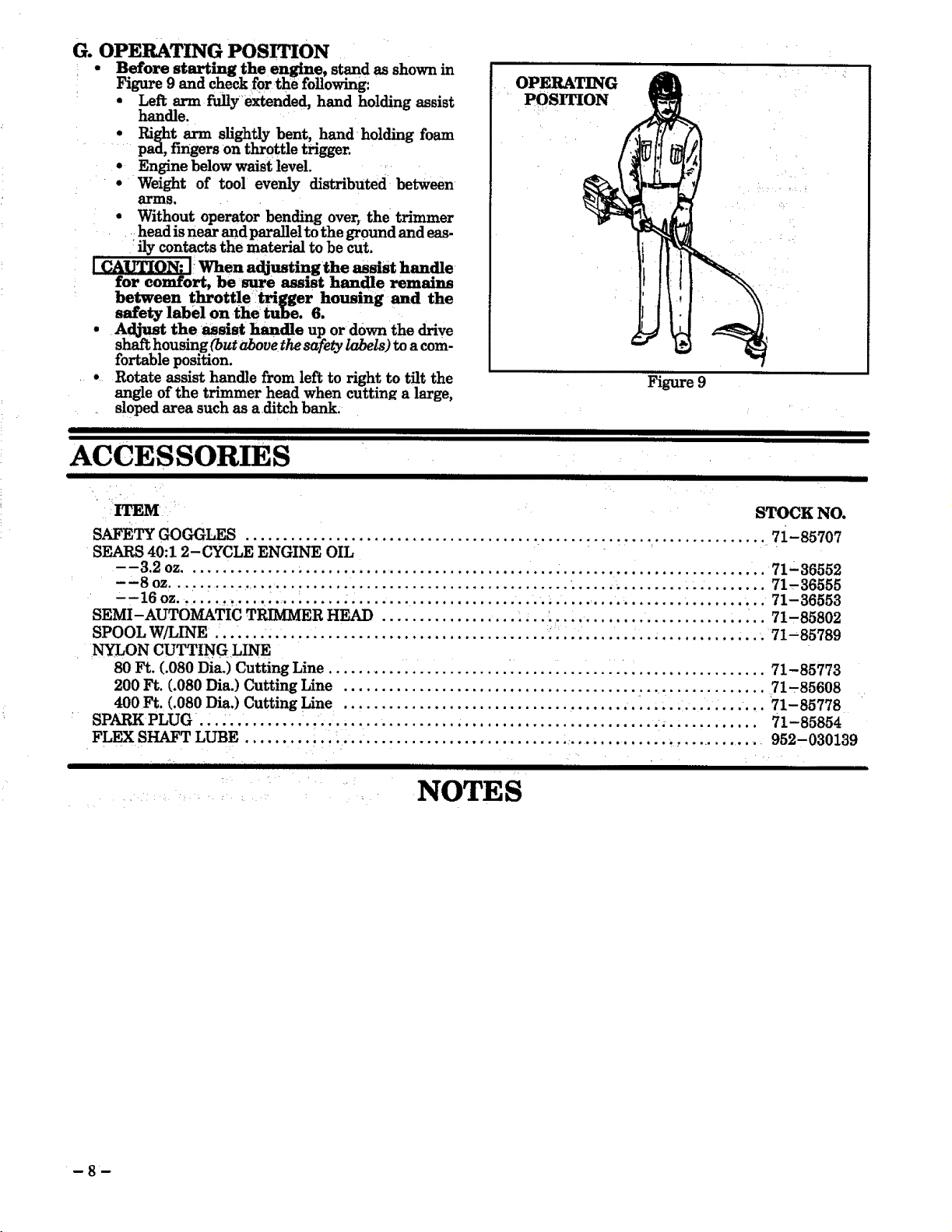
G. OPERATING POSITION
• Before starting the engine, stand as shown in
Figure 9 and check for the following:
• Left arm fully extended, hand holding assist
handle.
• Right arm slightly bent, hand holding foam
.... pad, fingers on throttle trigger.
° Engine below waist level.
° Weight of tool evenly distributed between
al'Ins.
• Without operator bending over, the trimmer
head is near and para_el to the ground and eas-
fly contacts the material to be _t.
When adjusting the assist handle
for comfort, be sure assmt handle remains
between throttle trigger housing and the
safety label on the tube. 6.
• Adjust the assist handle up or down the drive
shaft housing (but above the safety labels) to a com-
fortable position.
° Rotate assist handle from left to right to tilt the
angle of the trimmer head when cutting a large,
sloped area such as aditch bank.
IIIIIIIII I I
lii l
I IIIIIIIII III II I II
OPERATING
POSITION !
Figure 9
I IIII I I
ACCESSORIES
III IIIII I I IIIIIIII I II II
ITEM STOCK NO.
SAFETY GOGGLES
SEARS 40:1 2-CYCLE ENGINE OIL
......................................... ...... _._. !.... ............... 7i-85707
--3.2 oz ............... i ...... ............................ . ........................... 71-36552
--8 oz .... -. I, ............ ! ................................... ...... • ................... 71-36555
--16 oz .......... ,...... _.... ..... • ......................... • _.......... =................... 71-36553
SEMI-AUTOMATIC TRIMMER HEAD .................. _... _.... ................... ..... 71,85802
SPOOL W/LINE ... .... . ..... . .............................. :._... .................... .... 71-85789
NYLON CUTTING LINE
80 Ft. (.080 Dia.) Cutting Line ........................................................... 71-85773
200 Ft. (.080 Dia.) Cutting Line ....................................... _.................. 71,85608
400 Ft. (.080 Dia.) Cutting Line .. ! ........................... ............... i........ ... 71-85778
SPARK PLUG..... ........... ...+ ......................................... _.. .......... 71-85854
FLEXSHAFT LUBE ......... !... ....... • ......................... .... .......... +............ . 952-030139
III1[1111111111IIIII I I IIIIIIIII IIlll II II
....... : . NOTES
8

OPERATION
[I I I1[[111 IIIIIIIIII 111mill ,, III1[[ I IIIIIIIIII [I //_1111 I[[ I [[[[[[[[[[[[[[[i [[[
BEFORE STARTING ENGINE:
WARNING
&
GASOLINE
The two'cycleengineon thisproductrequiresa fuelmix-
tureof regularunleadedgasolineand a high qualityen-
gineoilforlubricationofthe bearingsand othermoving
parts.The correctfuel/oilmixtureis40:1(seeFuelMix-
ture Chart).Too littleoilor the incorrectoiltype will
causepoorperformanceand may causetheenginetoover-
heatand seize.
BE SURE TO READ THE FUEL SAFETY
INFORMATION IN THE WARNINGS
'AND SAFETY INSTRUCTIONS SEC-
TION OF THIS MANUA_ BEFORE YOU
BEGIN.
IF YOU _DO NOT UNDERSTAND THE
FUEL SAFETY SECTION, DO NOT AT-
TEMPT TO FUEL YOUR UNIT; SEEK
HELP FROM SOMEONE WHO DOES
UNDERSTAND THE FUEL _SAFETY
SECTION OR CALL THE CUSTOMER
ASSISTANCE HOTLINE AT
1-800-235-5878. _
2-CYCLE OIL:
CRAFTSMAN 40:1 2 cycle oil is strongly recommended.
This oil is specially blended with fuel stabilizers for
increased fuel stability (extends fuel life up to 5 times
longer) and reduced smoke.
If CRAFTSMAN 2 cycle oil is not available, us e a good
quality 2 cycle AIR-COOLED engine off that: has a
recommended fuel mix ratio of 40:1.
IMPORTANT! Do not use:
• AUTOMOTIVE OIL
• BOAT OILS (NMMA, BIA. etc.)
These oilsdo not have properadditivesfor2,cycle,
AIR-COOLED enginesand cancauseenginedamage.
GASOLINE AND OIL MIXTURE
Mix gasoline and oil as follows:
• Consult chart for correct quantities.
Gasolineand oilmust be premixedina cleanapprovedfuel
container.Always usefreshregularunleadedgasoline.
IMPORTANT:. Experience indicatesthat alcohol
blendedfuelscalledgasohol(orusingethanolor metha-
nol)canattractmoisture,which leadstooil/gassepara-
tionand formationofacidsduringstorage.Acidicgascan
damage thefuelsystemofan enginewhileinstorage.To
avoidengineproblems,thefuelsystemshouldbeemptied
beforestoragefor30 days or longer.Drainthegastank,
then run the fueloutofthecarburetorand fuellinesby
startingtheengineand lettingitrun untilitstops.Use
freshfuelnext season. See STORAGE instructionsfor
additionalinformation.Never use engineor carburetor
cleanerproductsin the fueltank orpermanent damage
may occur.
FUEL STABILIZER
FuelStabilizerisan acceptablealternativeinminimizing
the formationoffuelgum depositsduring storage.Add
stabilizerto gasolinein fueltank or storagecontainer.
Alwaysfollowthe fuelmix ratiofound on the stabilizer
container.Run engine atleast10 minutes afteradding
stabilizerto allowthe stabilizertoreachthe carburetor.
You donothavetodrainthefueltank forstorageifyou are
usingfueistabilizer.
i
CRAFTSMAN 40:1 2 cycle engine oil is specially blended
with fuel stabilizers. If you do not use this Sears off, you
can add a fuel stabilizer (such as Craftsman No. 33500) to
your fuel tank.
• Do not mix gasoline and oil directly in the fuel tank.
FOR ONE GALLON:
• Pour 3.2 ounces of high quality, 2,cycle engine oil
intoan empW, approved one gallon gasoline con-
tainer.
Add one gallon of regular unleaded gasoline to the
gallon container, then securely replace the cap.
Shake the container momentarily.
The mixture is now ready for use. -Fuel stabilizer
can be added at this time if desired; follow mixing
instructions on the label.
FUEL MIXTURE CHART
40:1 Fuel:Oil Mix Ratio
Gasoline Oil (fl, oz.)
1 gallon 3.2
1.25 gallons 4.0
2.5 gallons 8.0

STARTFNG YOUR ENGINE
(For location of controls, refer to "Specifications,")
BEFORE STARTING THE ENGINE:
• Fuel engine. Move 10 feet (3 meters) away from fuel-
ing site.
The trimmer head will turn while starting the
l A WARNING l
engine.
r@
Rest engine and shield on ground, suppoi'ting trim-
mer head off ground.
Remove and discard the plastic shipping
guard on the primer bulb (if so equipped).
STARTING A COLD ENGINE OR WARM ENGINE
AFTER RUNNING OUT OF FUEL:
• Make sure the switch is in the "On" position.
• Move the choke lever to_the "Full Choke" position.
• Slowly press the primer bulb 6 times.
• Squeeze and hold the throttle trigger. Keep the
throttle trigger fully squeezed until the engine runs
smoothly.
• Pull starter rope sharply 5 times.
STARTING A WARM ENGINE THAT HAS NOT
RUN OUT OF FUEL:
• Make sure the switch is in the "On" position.
• Move the choke lever to the "Half Choke" position.
• Squeeze and hold the throttle trigger. Keep the
throttle trigger fully squeezed until the engine runs
smoothly.
• Pull starter rope sharply until engine runs, but no
more than 5 pulls.
• Allow the engine to run 15 seconds, then move the
choke lever to "Off Choke."
NOTE.. If engine has not started, pull starter rope 5
more pulls. If engine still does not run, it is probably
flooded. Proceed to "Starting a Flooded Engine."
• To stop the engine, move switch to the "Off" position.
STARTING A FLOODED ENGINE:
Flooded engines can be started by placing the switch
in:the "On" position and the choke lever in the "Off
Choke" position; then, pull the rope to clear theen-
gine of excess: fuel This could require pulling the
starter rope many times depending on how badly the
unit is flooded.
If the unit still doesn't start, call the Customer Assis-
tance Hotline at 1-800-235-5878.
1STARTING POS_ION l
NOTE: The en_ne may sound as if it is trying to
start before the 5m pull. If so, go to the next step im-
mediately.
• Move the choke lever to the "Half Choke" position.
• Pull the starter rope sharply until the engine runs,
but no more than 6 pulls.
NOTE:If the engine has not started after 6 pulls (at
half choke), check to make sure the switch and the
choke lever are in the proper positions. Then, move
the choke lever to the "Full Choke" position and
press the primer bulb 6 times; squeeze and hold the
throttle trigger and pull the starter rope 2 more
times. Move the choke lever to "Half Choke" and pull
the starter rope until the engine runs. but no more
than 6more pulls.
Ifthe engine still has not started, it isprob-
ably flooded. Proceed to "Starting a Flooded En-
_ne."
@
Allow the engine to run 15 seconds, then move the
choke lever to "Off Choke." Allow the unit to run for
30 more seconds at "Off Choke" before releasing the
throttle trigger.
NOTE." If engine dies with the choke lever at the "Off
Choke" position, move the Choke lever to "Half
Choke" and pull the rope until the engine runs.
@
To stop the engine, move the switch to "Off."
Ignition
Switch
Choke Lever
A WARNING
Avoid any bodily contact with the muffler when
starting a warm engine. A hot muffler can cause
serious burns.
- 10 -
Primer
Bulb

OPERATING INSTRUCTIONS
Bring the engine to cutting speed before entering
the material to be cut,
* Do not run the engine at a higher speed
than necessary. The cutting line will cut effi-
ciently when the engine is run at less than full
throttle. At lower speeds, there is less engine noise
and vibration. The catting line will last longer
and wilt be less likely to "weld" onto the spool.
iiiiiii i i i
• If trimmer head does not turn when the en-
gine is in operation, make sure the drive shaft
housing is properly seated in the engine shroud.
Refer to '_ssembly-Tube."
• Always release throttle trigger and allow
engine to return to idle when not cutting.
• To stop engine:
a. Release the throttle trigger.
b. Move ignition switch to the "Off" position.
H Hmmml u Hmmmllll n HHmlllllll I lU
USING YOUR TRIMMER
Goggles
Semi -_Automatic Trimmer Head
A. LINE TRIMMER SAFETY
1. OPERATOR
a. Always wear a face safety shield or gog-
b. Always wear heav_ long pants, long
c. Keep hair, f'mgers, and all other parts of the
d. Do not operate this tool when you are
e. Do not swing the tool with such force that
f. Never start or run the engine inside a
g. Keep handles free of oil and fuel.
, ,,,,
: _ 60 Foot
/" . _ ._ (20 meter)
.r Hazard Zone
_ (see Accessory list for proper p'art number)
m_J Use Only Genuine
SEARS
-_ Replacement Parts
gles. See "Accessories."
sleeves, boots, and gloves. Do not go bare-
foot or wear short pants, short sleeves, sandals,
jewelry, loose clothing, or clothing with loosely
hanging straps, ties, tassels, etc.; they can be
caught in moving parts. Secure hair so it is
above shoulder length. Being fully covered will
help protect you from pieces of toxic plants
such as poison ivy thrown by the blade, which
could be more of a hazard than touching the
plant itself.
body away from openings and moving parts.
tired, ill, or under the influence of alcohol,
drugs, or medication.
you are in danger of losing your balance.
closed room or building. Breathing exhaust
fumes can kill.
WARNING-THROWS OBJECTS
The rapidly moving line causes objects to be
thrown violently. The shield will not provide
complete protection to the operator or others.
The operator must wear a safety face
shield or goggles. Always wear heav_
long pants and boots. Keep others at least
30 feet (10 meters)away.
WARNING - HAZARD ZONE
This tool will throw objects and cut. Keep oth-
ers including children, animals, bystand-
ers, and helpers at least 30 feet (10 me-
ters) away from the operator and tool.
Stop the engine if you are approached.
A WARNING- DAMAGED
TRIMMER HEAD "
Trimmer head parts that are chipped, cracked,
broken, or damaged in any other way can fly
apart and cause serious injury. Do not use.
Replace damaged parts before using the
tool. . _ "
2. TOOL
a. Inspect the entire tool before each use.
Replace damaged parts. Check for fuel leaks
and make sure all fasteners are in place and se-
curely fastened.
b. Use only .080" diameter Sears Laser Line.
Never use wire, rope: string, etc. '
c, Be sure the shield is properly attached.
d. Make sure the trimmer head is properly
installed and securely fastened. Refer to
"Assembly."
e. Make carburetor adjustments with the
drive shaft housing supported to prevent the
trimmer line from contacting any object.
f. Keep others away when making carbure-
tor adjustments.
g. Use only genuine Sears accessories or attach-
ments as recommended.
3. CUTTING
a. Inspect the area to be cut before each
use. Remove objects (rocks, broken glass,
nails, wire, string, etc.) which can be thrown or
become entangled in the trimmer head.
b. Always keep the engine on the right-
hand side of your body.
c. Hold the tool firmly with both hands.
d. Keep firm footing and balance. Do not
over- reach.
- 11 -

e. Keep the trimmer headbelow waist level.
f. Do not raise the engine above your waist.
g. Keep all parts of your body away from the
trimmer line the engine is running.
h. Keep all parts of your body away from a
hot muffler.
B. TRIMMER LINE ADVANCE
• The trimmer line will advance approxi.
mately 2 inches each time the bottom of the
trimmer head is tapped on the ground with
the engine running at full throttle.
• The most efficient line length is the maxi-
mum length allowed by the line iimiter.
• Always keep the shield in place when the
tool is being operated_ Figure 10.
• To Advance Line:
1. Operate.the engine at full throttle.
_ 2. Hold the trimmer head parallel to and above
the grassy area.
3. Tap bottom of trimmer head lightly on ground
one time. See Figure 10. Approximately 2
..... inches uf line will be advanced with each tap.
Always tap trimmer head on a grassy
.... area. Tapping on surfaces such as concrete or
asphalt can cause excessive wear to the trim-
mer head.
NOTE." if the line is worn down to two
inches or less, more than one tap will be re-
quired to obtain the most efficient line length.
C. CUTTING METHODS
. A I
Use minimum speed and do not crowd the line l
when cutting around hard objects (rock, l_ravel,
fence posts, etc), which can damage the trimmer I
head, become entangled in the line, or be i
thrown causing a serious hazard. [
• The tip of the line does the cutting. You will
achieve best performance and minimum line wear
bynot crowdingthe line into the cutting area. The
right and wrong ways are shown in Figure 11.
• The line will easily remove grass and weeds
from around walls, fences, trees and flower
beds, but it also can cut the tender bark of
trees or shrubs and scar fences. To help avoid
damage especially to delicate vegetation or trees
with tender bark, shorten line to 4-5 inches (10 -
12.5 cm) and use at less than full throttle.
• For trimming or scalping, use less than full
throttle to increase line life and decrease
head wear, especially:
- during light duty cutting.
- near objects around which the line can wrap
such as small posts, trees or fence wire.
• For mowingor sweeping, use fuji throttle for
a good clean job.
I AWARNING I
IAlways wear eye protectmn_ Never lean over the I
]trimmer head. Rocks or debris can ricochet or l
ibe thrown into eyes and face and cause bHnd-I
[hess or other serious i_ury.
1. TRIMMING - Figure 12. Hold the bottom of
the trimmer head about 3 inches (7.5 cm) above
the ground and at an an_le. Allow only the tip of
the line to make contact. Do not force the trimmer
line into the work area.
- 12-
i. Use only for jobs explained in this man.
ual.
A WARNING
Avoid any bodily contact with the muffler when
starting a warm engine. A hot muffler can cause
sermus burns.
III III I III
A WARNING
Use only .080" diameter SEARS brand line.
Other sizes of line will not advance properl_ Do
not use other materials such as wire, . string,
rope, etc. Wire can break off during cutting and
become a dangerous missile that can possibly
cause sermus m_ur_.,,,....
: b WAP_ING I
Use minimum speed and do not crowd the line l
when cutting aroun.d hard objects (rock, t_ravel, I
fence posts, etc), whmh can damage the trimmer ]
head, become entangled in the lme; or bel
thrown causing a serious hazard_ " I
To Advance Line,
Tap Bottom Of
Trimmer Head On
Ground One Time.
IHIIIIIIII I I II
Tip of the Line Line Crowded Into
Does The Cutting Work Area
3 Inches
Above Ground
RIGHT WAY WRONG WAY
• _ " • Above Ground
" _'_" 3 Inches
2. SCALPING - FIGURE 13. The scalpingtech-
_! tuque" removes unwanted• vegetation.,, Hold bot-
tom of the trimmer head about 3 (7.5 cm) above
ground and at an angle. Allow the tip of the line to
strike the ground around trees, posts, monu-
ments, etc. This technique increases line wear.
Line Limiter Cuts Line
Length.
Figure 10
Figure 11
_ !"3 Inches
Figure 12
Above Ground
Figure 13

3. MOWING' Figure 14. Your trimmer is ideal
mowing in places Conventional lawn mowers
cannot reach. In the mowing position, keep the
linb _paraUel to the ground_ Avoid pressing the
head into the ground as this can scalp the ground
and damage the tool. " _ ,
4. SWEEPING-Figure 15. Thefanningacti°n
of the rotatingline can be used for a quick and easy
clean up. Keep the line parallel to and above ._e
surfaces being swept and move the tool fro '
to side.
_ltttttttttttttt itttttttttt ttttttt IIi ' it]tttttttttttttt /lltt tttul[,,,,
D.LINE REPLACEMENT
, For!proper line feed:
- Use, only genuine SEARS pre-wound
spools and ,080" diameter SEARS brand
l{ne. Use of other types of spools or lines can
.... result in excessive breakage, line welding and
' _impropr line feed. i
- Pre-wound spools offer the most conven-
ient method for replacing line as well as
...... optimum pe_ormance, _i.........
• Always clean dirt and debris from spool and
hub when performing an_. type maintenance.
1. Installing Spoolwlth Line
a. Hold the trimmer headas shown in Figure 16.
Press the lock tab and turn the lock ring as
shown in Figure 16.
b. Remove the lock ring, tap button, and spool.
Figure 17.
c. Clean dirt and debris from all parts.
d. Inspect alltrimmer headparts for damage. Re-
place damaged parts.
| AWARNING i I
[Trimmer head parts that are chipped, cracked, ]
]broken, or damaged in _ other way can flY[
|apart and cause serious injury. Do not use. Re-[
Jplace damaged parts before using the tool. I
NOTE: The aluminum line saver (Figure 18 ) can
become worn during use. After a groove is worn
into line saver, remove it from trimmer head, turn
it upside down, and reinstall it (with spool re-
moved) to provide a new wear surface.
........ Aw G ........ I
The line saver must be installed only from the in- i
side of the trimmer head. If installed on the out-]
side of the trimmer head, the line saver can fly[
off and become a dangerous missile, t
e. Insert the end of the line through the line saver.
Figure 18. Place spool in trimmer head. Press
spool down, then turn it enough to lock lugs on
spool under lugs on drive gear. Figure 17.
NOTE: Make sure the line is not caught between
the rim of spool and the wall of trimmer head.
f. Replace the tap button. Align the lock ring
over the catches on the hub; push the lock ring
down on the hub and turn it clockwise until the
catches lock into place. Figure 18.
I A WAm NQ i
All catches must be fastened and the lock tab]
latched in the Lock Ring. If installed mcor-[
reet_, the I_.ck Ring can fly off and become a[
dangerous missile, i
Figure 14
SWEEPING
Figure 15
I w]
To Remove, Turn Lock Ring Counterclockwise
Turn Lock Ring Clockwise
Lock Tab
Figure 16
Tap
Figure 17
Catch
Line Lock Tab
Catch
Figure 18
g. M ak_esurelockring isproperlyfastenedby
pullingonitand tryingtoturnitcounterclock-
wise.It"itcomes off,reinstallitproperly.
h. Pullon the lineto change the spoolfrom the
lockedpositiontotheoperatingposition.
i. Obtainthecorrectlinelength(4-6 inches)by
pressingthetapbutton(Figure19 )and pull-
ingon thelineagain.
Each time thetapbuttonispressed,ap-
proximately2 inchesoflinecanbepulledfrom
thetrimmerhead. Figure19.
\
Catch
- 13 --

2. Spool Replacement
a. Replace the spool when the square corners on
the lu_ are rounded off, reduced in size, or bro_
ken off. Figure 20.
b. To replace thespool, follow the instructions in
"Installing Spool with Line." .......
3. Installing Line on Spool
To replace the Line on existing Spool:
a. Follow "Installing Spool w/Line," steps
"a_-d." and remove any line remaining on
the spool ..... ..........
b. Use a 40 foot length of.080" SEARS brand
line.
c. Insert 1/16" to 1/8" of the end of the line
through the hole in the spool. Figure 21.
Allow no more than 1/8" line to extend in-
side the spool.
d. Wrap the line onto the spool fLrmly and
evenly in a clockwise direction as shown by
the arrow on the Spool. Figure 21.
NOTE." The line must be wrapped fLrmly and
evenly for proper line feed.
e. Follow "Installinff Suool with Line." steus
"e i"
m
• _ ' • Q '
Approximately 2/Inchesof Line *Can
f Be PulledFrom the Trimmer Head
i_I/Each Time the Tap Button is Pressed.
,,,,mH,,,,H HH I •
Figure 19 .....
WORN
SPOOL
Figure 20
For best results, use only .080"
SEARS brand line.
Lug
If the line breaks off or backs up inthe trim-
mer head, follow "Installing Spool w/Line,"
steps "a.-d." Pall slack in line until the line is
tightly wound on the spool, leaving 4-6 inches of
extended line. Continue with steps "e.-i."
Wrap Line on
Spool as
Shown by Arrow Line
4. Trouble Shooting the Trimmer Head and Line
• Does not advance or breaks while
cutting_
.Improperly wound onto spool.
Line size incorrect.
.... Too little line outside head.
NOTES
L
Figure 21
.IH
• Pulls backinto head:
- Too little llne outside of head.
• Welds onto spool:
- Line size incorrect.
- Crowding line against material being cut.
Cutting at higher speeds than necessary.
- t4 -

CUSTOMER RESPONSIBILITY--
GENERAL MAINTENANCE
A. MAINTENANCE SAFETY
1. Maintain the tool according to recom-
mended procedures. Keep the cutting line at
the proper length.
2. Never start the engine with the clutch
shroud removed. The clutch can fly apart and
cause serious injury.
3. Disconnect the spark plug before perform-
ing maintenance except for carburetor adjust-
ments.
4. Make carburetor adjustments with tube
supported to prevent the trimmer line from
contacting any object.
5. Keep others away when making carburetor
adjustments.
B. AIR FILTER
"_ A dirty air filter decreases the life and
performance of the engine and increases fuel con-
sumption.
Do not clean the air filter in gaso-
-line or any other flammable solvent; doing
so can create a fire hazard.
Clean the air filter:
• Always after 6 tanks of fuel or 5 hours of
operation, which ever is less...
• More frequently, in dusty conditions.
1. Loosen the two screws onthe air filter cover
enough to remove the cover from the en-
gine. Figure 22.
2. Remove air filter from the cover. Figure 22.
3. Wash f'flter in soap and water.
4. Squeeze filter dry and replace in cover.
5. Reinstall the air fdter cover, making sure
the choke exit slot (Figure 22 ) is placed
over the choke lever,
m i.i imwmm Ht
C. DRIVE SHAFT LUBRICATION
• Lubricate the Drive Shaft:
- After each ten (10) hours of operation.
- Before operating if the tool has been
stored for 90 days or longer.
• To order drive shaft lube, see the Accessory
list for proper part number.
A WARNING. i
]If the engine is hot, avoid touching the muffler. ]
|A hot muffler can cause serious burns. ]
Lay drive shaft on a clean sur-
face. Avmd laying the shaft on floor, ground,
or on any other surface that may have dirt
or debris. Even after wiping shaft, grease
residue can pick up particles that can cause
damage or premature failure.
Take care to avoid i_ury your
hands and fingers wzth broken wires when
checking for damage or wiping the drive
shaft. A cloth will not prevent broken wires
from puncturing or tearing your skin.
• Use the following procedure:
1. Remove the screw and nut from the throttle
trigger housing. Figure 5.
2. Hold throttle trigger away from the foam grip
and remove the barrel endof the throttle cable
from the throttle trigger. Figure 3.
6. Be sure trimmer head stops turning when
engine idles. See "Carburetor Adjustments."
7, Replace trimmer head parts that are
cracked, chipped, broken, or damaged in
any other way before using the tool.
8. Use only .080 (2mm) diameter Sears Laser
Line. Never use wire, rope, string, etc.
9. Use only genuine SEARS replacement
parts as recommended.
10. Inspect the entire tool. Replace damaged
parts. Check for fuel leaks and make sure all fas-
teners are in place and securely fastened.
Choke
Exit Slot
Choke Lever
If replacing the air filter, refer to the
Accessory list for proper part number.
I CAIYrION: [ Make sure the air _ter is fitted
into the corners of the cover to keep dust
from entering the engine and causing en-
gine damage.
3. Carefully pull throttle cable out of foam grip.
4, Loosen the clutch shroud screws and remove
the tube from the engine.
5. Remove drive shaft from the tube. Figure 23.
6. Check the drive shaft for broken wires, twists
or kinks, and replace if damage is found.
7.
Using a clean cloth, wipe the drive shaft thor-
oughly to remove any old grease. Figure 23.
Apply a uniform coat of lube to the entire sur-
face of the drive shaft.
9. Inject the remaining contents of the container
into the top of the tube.
10.Replace drive shaft in the tube. Figure 23.
ll.Reassemble tube to the engine. Tighten clutch
shroud screws securely.
Drive Shaft
Drive Shaft
Housing
Air Filter Corners
Figure 22
Figure 23
Air
Cover
- i5 -

D. CARBUF TOR ADJUSTMENTS
YOITR CRAFTSMAN PRODUCT HAS BEEN DESIGNED AND MANUFACTURED TO SPECIFI-
CATIONS THAT .P_DUCE _ EMISSIONS. A_er your unit has been run for 5 hours, the en-
gine has broken -m" To ensure that your unit is at peak perfo,rmance and producing the least amount
of harmful ennsslons after b.reak-m, have your SEARS Service Center/Department adjust your car-
buretor for optimum operating conditlous.
NOTE.. Properly adjusting the carburetor is a complicated task. Read all warnings and instructions
vbefore starting adjustments. If you do not think that you completely understand all warn.
let _'our SEARS Service Center/Department perform these adjustments.
A WARNING 2, BASIC CARBURETOR SETNNGS
carburetor adjustments with the lower
end supported to prevent the trimmer Hne from
contacting any object. Hold tool with your hand;
do not use optional shoulder strap for support.
Keep others away when making carburetor ad-
ljustments.
A WARNING
Serious injury to the operator and others can oc-
cur if the carburetor fs not properly adjusted.
• P0orengine performance canbe aresult of
other causes such as dirty air filter, carbon
build-up on muffler outlets, etc. :See
"Trouble Shooting Chart" before proceed-
ing with carburetor adjustments.
• The carburetor has been carefully adjusted
at the factory. However, the operator must
be sure that adjustments are made when
any of the conditions occur as mentioned on
the next page in "Troubleshooting Sugges.
tions".
• Very small adjustments can affect engine
performance. It is important to turn the screw a
, very small amount per adjustment and test per-
formance before making further adjustments.
Each adjustment should be no more than the
width of the slot in the adjusting screw.
• This is a complicated task and it is impor-
tant to follow instructions in sequence as
indicated.
1. TROUBLESHOOTING SUGGESTIONS
- Engine will not continue to run at idle posi-
tion. See "Idle Speed Adjustment" and "Low
Speed Mixture Adjustment.
- Trimmer head continues to spin when the en-
Fine idles. See "Idle Speed Adjustment" and
"Deceleration Check,"
- Engine dies or hesitates when it should accel-
erate. See '_kcceleration Check."
Loss of cutting power which cannot be cor-
rected by cleaning the air fflten See "High
Speed Mixture Adjustment."
-Engine does not return to idle from full throt-
tle within 2 seconds. See "Deceleration
Check."
- Engine will not run. See "Trouble Shooting
Chart." Then, if the carburetor requires ad-
justment, begin with "Basic Carburetor Set-
tings."
.
[ The trimmer line will be spinning during most of
[this procedure. Wear your protective equipment
[ and observe all safety instructions.
- 15 -
NOTE." In most cases, your engine can be made to
run properly with minor carburetor adjustments.
Refer to "Trouble Shooting Suggestions" in the
left column for the condition you are experiencing
and follow the instructions. The basic carburetor
settings are provided below.
a. Turn.the low speed mixture screw and the high
.... speed mixture screw (Figure24) clockwise
until they stop. Do not turn screws until they
are tight as damage to needle seats can occur.
b. Turn the low speed mixture and high speed
mixture screws between three-quarters and
one full turn counterclockwise.
3. ADJUSTING PROCEDURE
a. PREPARATION
1. Use fresh fuel mix. See Fueling section.
2. Make sure the line extends to the length al-
lowed by the line limiter to provide correct
toad on engine.
3. Start the engine. Cut grass for 3minutes to
warm engine. The engine must be at operat-
ing temperature before carburetor adjust.
ments can be performed correctly.
b. IDLE SPEED ADJUSTMENT
1. Allow engine to idle.
2. Adjust idle speed screw (Figure 24 ) until
the engine continues to run without stall-
: ing and without the trimmer head moving.
- Turn screw clockwise to increase engine
speed if the engine stalls or dies.
- Turn screw counterclockwise to slow en-
gine down and/or to keep trimmer head
from turning.
3. Follow instructions in '_cceleration
Check" and "Deceleration Check."
4. No further adjustments are necessary
if trimmer head does not turn at idle
speed and performance is satisfactor_
Re. check idle speed after each adjustment. The
trimmer head must not turn at idle speed to
avoid se_0us in_ur_ to the operator andothers.
c. ACCELERATION CHECK
1. Allow engine to idle.
2. Squeeze trigger fully
3. Repeat step "b.)" until smooth acceleration
NOTE: It may be necessary to repeat "b. Idle
Speed ,,A_'ustment" through "c. Acceleration
Check, to obtain correct adjustments.
4. Follow instructions in "d. Deceleration
A WARNING [
a.) If performance is satisfactor_ pro-
ceed to "d. Deceleration Check."
b.) If the engine does not accelerate
smoothi_ turn the low speed mixture
screw (Figure 24 ) counterclockwise a
small amount (no more" than the width
of the slot in the adjusting screw).
is obtained.
Chect_"

d, DECELEHATION CHECK •
1.. Allow engine to idle, then squeeze throttle
t_gger fully.
2. Allowengineto run at fullspeedforabout 1
second. _ ....
3. Release the throttle trigger to the i_e posi-
tion and listen to the deceleration of the en-
gine. It must return to idle smoothly and
within i to 2 seconds.
a. If performance is satisfactor_ pro-
ceed to step "4."
• b. If the engine slowly or erratically
returns to idle or idles erraticall_ ;
repeat "Idle Speed Adjustment" or con-
.tinue through- Low Speed Mixture and
High Speed Mixture Adjustments to ob-
•.... tain proper deceleration. • ,_
4. Recheck idle speed.
e. LOW SPEED MIXTI2P_ ADJUSTMENT :
1. _Allow engine to idle. ..........
2. Turn the low speed mixture screw (Figure
24 ) slowly clockwise until the speed starts
to drop. Note this position.
3. Turn the low speed mixture screw Counter-
clockwise until speed increases and then
_ startsto drop again. Note this position. •
4. Set the low speed mixture screw at the mid-
point betweenthe twopositions. _
5, :.Follow instructions ' in '_cceieration
Check" and "Deceleration Check,"
f. HIGH SPEED _ ADJUSTMENT _
[__Vo not operate engine, at full
throttle for prolonged periods.while mak-
ing high speed adjustments as damage to
the engine can occur. ........
..,,,,,,,, H, Hm ll.mlmmmmm
1. Support:the lower endsothe trimmer line
is offthe groundand w_ not make contact
with anyobject, .... .
2. Allow engine to idle, then squeeze throttle
trigger fully.
]_I_]_ Perform steps "3.,' through "5." at full
throttle.
3. Turn high speed mixture screw (Fig-
ure 24 )very slowly clockwise until engine
speed is reduced. '
" - 4. Turn high speed mixture screw very slowly
....... counterclockwise. Stop when the engine
....... beginstorun roughly:
5. Turn screw slowly the minimum amount
: ' :_ _clockwise until the engine runs smoothly.
: 6. Follow instructions in '_celeration
':! Check" and "Deceleration Check"_:
.. partment.
m
H]ghSpeed, ,_
Low Speed Adjustment Screw
......" "Nose Cone"
/
i _ / ::AirFilter_,,
Idle Speed :
....Adjustment .....
Screw ........
• Figure 24
IHI i!111
E. SPARK PLUG -- Replace the spark plug yearly..
,, i, ,,,m,,,,,,,,,,,,,, HIll iiiiiiiiiiiiiiiiiiiiiiii iii iiii llllilll
F. STARTER ROPE
• Rep!_e a starterropethatbrdaksl_
Neverstart engine with clutch shroud .removed; I
dutch will fly apart and cause serious gnjury. _ 1:
,
A WARNING
Do not remove pulley tab and screw or pulley.
iThe springbeneath the pulley is under tension
and canfly out and cause serious injury. If any
'part of pulley _honsing _assembly Is damaged
other than the rope, do not use tool. Take it to
your SEA!_S Service Center_epartment.
1. Disconnect spark plug wire. Figure 25.
2. Remove the screw and nut from the throttle trig-
• get housing. Figure 25.
3. Hold throttle trigger away from the foam grip and
remove the barrel end of the throttle cable from
'_the throttle trigger. Figure 3.
4. Carefully pull throttle cable out of foam grip_
5. Remove the four clutch shroud screws with the
small hex wrench provided. Figure 25.
6. Separate clutch shroud from engine. Figure 25.
Use only a hand tool to remove the clutch, Do not
use any type ofmotor_zed tool or strike the clutch
in any way. Otherwise, the Vlutch willfly apart
and cause serious i_ury. ' .
. SCrews •
Clutch
:Wire Shroud_ *• •
•ThrottleTriggerNut
Clutch
Shroud
Throttle
Trigger
Screw
'Figure 25
-17"

7. Hold the "fiats" of the clutch with an adjustable
wrench as shown in Figure 26 (inset) and remove
the nut counterclockwise with a 9/16" socket
wrench.
Nut
NOTE.. Clutch will slide off the crankshaft intact.
Do not disassemble clutch.
8. Remove the beveled washer, clutch, and large fiat
washer as shown in Figure 26.
9. Remove pulley housing from engine. Figure 26.
10. Remove the rope retainer screw and remove any
remaining rope. Figure 27.
11. Hand _rn the pulley clockwise as far as it will go.
12. Turn the pulley counterclockwise until the pulley
notch is aligned with the housing notch next to the
retaining tab and screw. Figure 28.
13. Next, turn the pulley one complete turn counter-
clockwise until the notches are aligned again.
14. Insert the hex wrench into the hole formedby the
notches to hold the pulley in position. Figure
28 (inset-upper lei_).
15. Use a 42" length of replacement rope.
16. Move away 10 feet (3 meters) from thefuel tank
with the replacement rope, Use a match and melt
both ends of the rope to prevent fraying.
17. Pull melted ends through a thick, clean rag while
rope is still hot to obtain smooth, pointed ends.
18. Insert one end of the rope through the handle and
secure with a knot. Leave a 3/16" pigtail behind
the knot. Figure 28 (inset-upper right).
19. insert the other end of the rope through the rope
exit hole into the inside of the housing, into the
pulley and up through the pulley hole. Figure 28.
20. Wrap the rope counterclockwise around the
pulley ratchet and tuck loose end under the rope
at the pulley hole. Figure 28. Leave a 1 inch tail
laying fiat on top ofthe pulleybetween the retainer:
riband the retainer screw!post. Figure 28..
2!, Reinstallrope retainer screwinto screw post. Fig-
ure 27. Tighten until the washer is snug.
Beveled Washer
(Curved Toward Clutch) Nut
Pulley
Hex m_
Wren__
Rope
Exit Hole
Pulley
Large Flat
Washer
Clutch
Spacer /_.._
Figure 26
_"--- Rope
Retainer Screw
Washer
Screw Post
Figure 27
NOTE." Do not overtighten the screw. Overtightening
the screw can cause the threads in the screw post
to strip out.
22. Hold the rope taut at the rope exit hole so the
pulley will not move. Remove hex wrench.
23. Slowly feed rope into the pulley housing.
24. Make sure the spacer is in place. Figure 26. Re-
verse steps 1 through 10 to re-assemble.
When reinstalling the clutch,
tighten the nut until the beveled washer is
flattened against the clutch. Over or under
tightening nut can cause engine damage.
- 18-
Pulley
Ratchet" _
Pulley
Hole
Notch
Rope
T_!
Pulley
Tab and
Screw
Figure 28

........ STORAGE------ --r------
i i //1_111 i i . _ll ill _ , ii
immediately prepare your unitfor storage at the end of the
season or ifitwill not be used for 30 days or more.
WARNING:
ALLOW THE ENGINE TO COOL, AND SE-
CURE THE UNIT BEFORE STORING OR
TRANSPORTING IT IN A VEHICLE.
STORE UNIT AND FUEL IN AN AREA
WHERE FUEL VAPORS CANNOT REACH
SPARKS OR OPEN FLAMES FROM WA-
TER HEATERS, ELECTRIC MOTORS OR
SWITCHES, FURNACES, ETC.
STORE UNIT WITH ALL GUARDS IN
PLACE: POSITION SO THAT ANY SHARP
OBJECT SUCH AS BLADES CANNOT
ACClDENTLY CAUSE INJURY TO PASS-
ERS BY.
STORE THE UNIT OUT OF THE REACH
OF CHILDREN.
GAS TRIMMER/BRUSHCUTTER STORAGE
INSTRUCTIONS
if your tdmmer/brushcutter is to be stored for a period of
time, clean itthoroughly Priorto st_6rage.Remove any dirt,
sawdust,leaves, oil,grease,etc. Storeina clean dryarea.
• Clean the entire unit.
• Clean air filter. Refer to "Customer Responsibilities".
• Open the linehead assembly and clean any dirt,grass
or debris that has collected. Inspectthe cutting line, if
old (chalW look and stickyto the touch), remove and
discard. Installfresh new linethe nexttimeproductisto
be used.
• Lightlyoil external metal surfaces to prevent rustfrom
forming.
• handling blade. The blade is sharp and
CAUTION: Wear protective gloves when
can cut you even when it is not moving_
ENGINE
Never useengine orcarburetorcleaner productsinthefuel
tankor permanent damage may occurtofuel system com-
ponents.
Follow these instructions:
a. Drain the fuel from the unit intoan approved
fuel container.
b. Drain the fuel lines and carburetor by starting
the engine and lettingitrun untilit stops.
c. Allow the engine to cool before storage.
IMPORTANT: it isimportant to preventgum depositsfrom
forming inessentialfuel system partssuch asthe carbure-
tor,fuel filter,fuel lineor tankduring storage. Also,experi-
ence indicates that alcohol blended fuels, th0se.that use
ethanol or methanol (called gasohol or oxygenated fuel),
canattract moisture and form acidic gas whichwitldamage
your engine. To avoid engine problems, the =fuelsystem
shouldbeemptied before storage of 30 claysor longer.
NOTE: Fuel stabilizerisan acceptablealternative in mini-
mizingthe formation offuel gum deposits duringstorage.
Addstabilizertothe gasoline inthe fueltankorfuel storage
container. Always follow the mix instructionsfound onsta-
bilizer container. Run engine at least 5 minutes after ad-
ding stabilizer to allow stabilizer to reach the carburetor,
Craftsman 40:1 2-cycle engine oil is specially
blended withfuel stabilizers. If you do not usethisSEARS
oil, you can add a fuel stabilizer (such as Craftsman
#33500) to your fuel tank.
• Remove spark plugand pour1 teaspoon of 40:1 oilmix
throughthe spark plug opening. Slowly pullthe starter
rope8 to 10 times to distributeoilto innerengine sur-
faces.
• Replace spark plug with a new one of the recom-
mendedtype and heat range. Referto "Product Speci-
fications".
• Clean airfilter. Refer to "Customer Responsibilities".
• Reinstall all covers and hardware removed for access;
tighten all screws and fasteners.
• Check entire unit for loose screws,nuts, and bolts. Re-
placeany damaged, broken, or worn parts.
• Use fresh fuel havingthe propergasoline to oilratio at
the beginning of the next season.
• If your unit is equipped with a blade, remove it from the
unit. Referto "Assembly". Apply a coating of oil to the
entire surface of the blade and wrap it in heavy paper,
cloth, or plastic. Also apply a lightcoat of oil to gear
housing threads, then tighten blade nut securely for
storage.
° Reassemble all loose parts,being sure that allhandles
and guardsare inplace and are securely fastened. Re-
place any damaged parts.
OTHER
• Do not store gasoline from one season to another.
• Replace your gasoline can if your can starts to rust.
Rust and/or dirt inyour fuel system will cause prob-
lems.
• Store your unitina well ventilated area andcovered, if
possible,topreventdustand dirtaccumulation. Do not
cover with plastic. Plastic cannot breathe and wiltin-
duce condensation and eventual, rust or corrosion,
IMPORTANT: Never cover unit while engine and exhaust
areas are stillwarm.
- 19-

i.l.lll, i. illllli iii i ii
SYMPTOM
ii J
Engine will not
start or will run
only for a few
seconds after •
starting.
J Ill
Enginewillnot
idleproperly.
Enginewillnot
accelerate,lacks
power,ordies
under a load.:
Engine
smokes
excessively.
Engine runs hot.
,,,, i
CAUSE P_MEDY .
ii i i i ml llll '
1. Fueltank empty, i::i1. Fi_ tankwith correctfuelmixture :
2. Engine flooded, i:2..See "StartingInstructions."
3. Sparkplugnot fLdng; 3: Installnew plug/checkignitionsystem.
4. Fuel not reaching carburetor.
5. Carburetor requires adjustment.
6. None of the above.
4. Clean fuel filter; inspect rue! line.
5. See "Carburetor Adjustments?'
...... 6. Contact your Sears Service Center/Dept.
' 1. See "Carburetor Adjustments."
2. None of the above.
ill ill ii . Jl i .. iJ
1. Air filter dirt_.
2. Spark plug fouled.
3; Carburetor requires adjustment.
4. Mufiler outlets plugged.
:5.None oftheabove. •
i
2. Contact your Sears Service Center/Dept.
1. Cleanorreplaceairfilter.
•.... 2. Cleanorreplacesparkplug and re-gap.
3. See "CarburetorAdjustments."
4. ContactyourSearsServiceCenter!Dept.
5. ContactyourSearsServiceCenter/Dept.
1.Air filterdirty. I.Clean orreplaceairfalter.
2. Fuelmixture incorrect. .... 2.
3. Carburetorrequiresadjustment.
See "Fueling Your Unit." •
3. See "Carburetor Adjustments."
1. Fuel mixture incorrect. L See "Fueling Your Unit."
L2. Carburetor requires adjustment. 2. See "Carburetor Adjustments."
' 3. Spark plugincorrect. : 3. Replacewith correctplug.
4. None oftheabove. 4. Contactyour SearsServiceCenter/Dept.
Cutting Head stops
under a load or
does not turn "
when engineis : '
accelerated.
Linedoesnot ' i. Lineimproperlyroutedinhead.
_I. Driveshaftnotengaged. 1. See '_kssembly,'.
2. Driveshaftbroken. • 2. Contactyour SearsServiceCenter/Dept.
• L ,,
., i i
° ' _11:Remove cover.Check linerouting.
advance or breaks 2. Line improperly wound onto spool. 2. Rewind line tightly and evenly.
while;cutting. 3: Line :
size incorrect. 3. Use only .080" (2ram) diameter Sears Laser
• i Line.
4. ;Too little line outside head. 4. Remove cover. Pull 4" (10 cm) of line to
: : i • _........... outside. ...........
5. Dirtaccumulatedoncover cut-outs. 5. Cleancovercut-outs.
Lineweldson spool. 1. Linesizeincorrect. _ _ 1. Use only.080"(2mm) diameterSearsLaser
_ Line: ..... .
2. Crowding line against material being cut. 2. Cut with tip of line.
3. Cutting at higher speed than necessary. 3. Reduce cutting speed.
Line releases • L Tap button engaged. Remove and clean tap button.
continuously. 2. Tap button knocked out of hub. 2. See "Installing Spool w/Line."
i .i
Line usage is .... 1. Line size incorrect. 1. Use only .080" (2ram) diameter Sears Laser
•excessive. _ [ " Line.
..... 2. Cutting at high speed around hard objects. 2. Reduce speed around hard objectsl
.... . ' 3. Crowding line against material being cut. 3. Cut with tip of line.
Line pulls back into i. Too little line outside of head. 1. Remove cover. Pull 4" (10 cm) of line to
head or feeds outside.
continuousl_ 2. Spool lugs broken. 2. Contact your Sears Service Center/Dept.
" 20 -

• JlUL_li ill illll illll i i
INDEX
,,,,,
ACCESSORIES 8 LINE (continued)
ADJUSTMENTS Replacement 13
Assist Handle ........................ 7 Rewinding on SpooI .......... 14
Carburetor .......................... L16 Safety .............................. 11
Line Advance ........................ 12 Size to Use ........... ............... 11
Module A_ Gap ...................... 2 Trouble Shooting . ................... 14
Spark Plug Gap ...................... 2 Welding on Spool ..................... 14
AIR FILTER ............................. 15 LUBRICATION, DRIVE SHAFT ........ 15
ASSEMBLY MAINTENANCE, CUSTOMER
Assist Handle ........................ 7 RESPONSIBILITY -- GENERAL
Tube ................................ 6 Air Filter ......................... ... 15
Preparation ......................... 6 Carburetor 17
Shield ................................ 7 Drive Shaft 15
Trimmer Head 7 Safety 15
ASSIST HANDLE ........................ 7 Starter Rope ..... .. .................. 17
CARBURETOR ADJUSTMENTS ......... 16 MODULE AIR GAP ...................... 2
CARTON CONTENTS ......... 5
.... "........... OIL, ENGINE
COLD ENGINE STARTING ............. 10 Ratio to Gasoline 9
CONTROLS .................... ...... 2 Types to use/not to use 9
CUSTOMER RESPONSIBILITY -- OPERATION
GENERAL MAINTENANCE Advancing the Line .................. 12
Air Filter ............................ 15 Mowing ............................. 13
Carburetor .......................... 17 Position ............................. 8
_LDrive Shaft ........... ............... 15 Safety ...................... . ....... 11
Safety .............................. 15 Scalping .................... ........ 12
Starter Rope ......................... 17 Starting the Engine .................. 10
Trouble Shooting Chart .. ............ 19
CUTTING METHODS .................... 12 Stopping the Engine .................. 10
TUBE ASSEMBLY ....................... 6 Sweeping ......... . .................. 13
ENGINE Trimming ........................... 12
Air Filter ............................ 15 PARTS LIST ............................. 21
Carburetor .......................... 16 PRE-OPERATION CHECKS ............ 9
Controls .......; ................. ... 2 PREWOUND SPOOLS ................... 13
Fuel Mixture ........................ 9 REPAIR PARTS LIST ..................... 21
Starter Rope..... .................... 17
Starting Instructions ................. 10 SAFETY INSTRUCTIONS, WARNINGS .. 3
Storage ............................. 4 SHIELD ................................. 8
Trouble Shooting .................... 19 SPARK PLUG GAP ...................... 2
ENGINE OIL SPECIFICATIONS ....................... 2
Ratio to Gasoline 9 SPOOL
Types to use/not to use 9 Installation ........................... 13
FILTER, AIR ....................... 15 Maintenance ....... 13
DRIVE SHAFT LUBRICATION .......... 15 Prewound ............................ 13
FUE_Gaso]ine/OilT. Mixture 9 STARTER ROPE REPLACEMENT ....... 17
Mixing Fuel ...................... ... 9 STARTING INSTRUCTIONS ............. 10
Pouring Fuel ........................ 9 STORAGE ............................. 4
Safety 9 TRIMiYIER HEAD
Storage ..... ........... ............. 4 Assembly ............................ 8
GASOLINE 9
,l*tto_Ql_JQot_*nm_moo_*_ • a
Ratio to Gasoline .................... 9 Removal 8
Types to useino_ to use .... ........... 9 Safety .............................. 20
IDLE SPEED ADJUSTMENT ............ 16 Shield .... ........ . ........... _...... 8
LINE TROUBLE SHOOTING CHART .......... 19
Advance ............................. 12 USING YOUR TRIMMER ................ 11
Breaking ............................ 14 WARM ENGINE STARTING ............ 10
Len_h: WARM ENGINE STARTING AFTER
Operation ........................ 12 RUNNING OUT OF FUEL .......... 10
• To Cut as Replacement .............. 14 L WARNINGS AND
Trouble Shooting Chart .............. 19
Speed ....................... ........ 11
Rewinding ........................... 14
Maintenance ........................ 11
SAFETY INSTRUCTIONS .......... 3
WARRANTY ............................. 2
-21 -

SEARS WEEDWACKER® REPAIR PARTS LIST - 358.799250-32cc
A WARNmG
\ 7 All repairs, adjustments
, " scribed in the Operator's
" formed by qualified serv-
3
____ Manual must be per-
.....,.,o...oo.o,,o.
ice personnel, i
18,-----_
19--i
32
_ -- 15
' 33 --.-_ ....
Operator's I
Manual {'
Key
:::No.
1
530-037497
2"
530-094891
3
8TD541025
4
530-010958
5
530-029445
6
530-015784
7 530-015785 Locknut
i,,, ,,
Throttle Cable Ass'y. 20 530- 093653
Drive Shaft Housing 21 952-030139
Locknut 22 530-015768
Anti-Vibe Handle 23 530-015774
DriVe Shaft Grip 24 530-010959
Screw 25 530-082425
28 8
Description No. No.
8 ....,530-069249 ShieldKit Ass'y.
9 STD51i005 'Screw
10 530-094570 Line Limiter: •
11 STD541410 Nut
12 530- 094551 Flexible Drive Shaft
13 530- 094543 Dust _Cup
14 530-092243 Screw
15 71,85802 Cutting Head Ass'y,
16 530-069252 "T" Handle Ass'y.
17 530-094592 Hub Azs'y.
18 530-093898 Line Saver
19 530-340007 _ Spring
- (Incl. 9, 10, & 11)
0_11
Key Part
26 530-015775
27 530-031111
28 530-031098
29 530-027598
30 530-029159
31 530-027600
32 530-092068
33 530-093897
34 71-85789
35 530-401183
36 530-092133
14
Description
Bracket
Shaft Lubrication
Nut
Screw "
Throttle Lever Ass'y.
Operator's Manual
Screw
Hex Wrench (5/32)
Hex Wrench (3/16)
Anti-Vibe Decal
Shaft Warning Decal
Shield Decal
Spring Cap
Drive Gear
Spool w/Line
Release Button
Cover
22

SEARS WEEDWACKER® REPAIR PARTS LIST 358.799250-32cc
1 2
94 /9
15
/19
I
I
[
I
I
32
36 37 38
23 24
/
20
26
12
27
f
29
9O/
76
77
52
62
75
43
"7
78
63
64
48
54
71 70
84
40
56
58
67 68
I Spark ]
Arrestor[
Kit I
\
91
Carb
Repair
Kit
\
60
I carb" ! El"-Z'_inel
\ \
85
86 87
63
[ Gasket !
23

SEARS WEEDWACKER® REPAIR PARTS LIST - 358,799250-32cc
Key i Part
No. j No.
1 530-015773
2 530-027529
3 530-027530
4 530-015849
5 530-015852
6 530-015254 "'
7 530-027526
8 530-037930
9 530-069247
10 530-014362
11 530-035349
12 t 530-019156
13 530-014347
14 530-047095
15 t 530-019154
16 530-027593
i7 : 530-027594
18 530-014015
t9 530-010960 :
20 530'015789
21 530-010934
22 530-015126
23 530-015772
24 530-015780
25 530-027546
26 530-027547
27 530-015771
28 530-014016
29 53O-027545
3O 530-027543
31- STD610603
32 530-015162
33 530-025875
34 t 530-019178
35 530-069275
36 530-032103
37 530-015787
38 530-019158
39 530-032102
40 530-069232
41 530-015777
42 530-027523
43 530"069257
44 530-036409
45 530-027525
46 530-039134
47 530-015128
48 530-012235
49 530-030077.
50 .530-015768
51 530-039136
Description Key
Screw
Air Filter Cover
Air Filter
No.
52
53
54 _
Part
No. Description
530-347987 Washer
530-027517
530-069291
Screw
Spacer
Wave Washer
Choke Shutter
:Air Filter Plate
Fuel Line Kit
Fuel Pick-up Ass'y.
Carburetor
Carburetor Gasket
Fuel Cap Ass'y. :
Shroud & Tank Ass'y.
(Incl. #9,10 & 13)
Crankcase!Shroud Gasket
2 Reed
Ass'y. (Incl. #20,21;28)
Connecting Rod Ass'y.
(Incl. Bearings) 72
Crankshaft Retaining Ring 73
Crankshaft Ass'y. :74
55
56
57
58
59
60
61
62
63
64
65
66
67
68
69
70
71
530-029395
530-027569
530-010961
530-094189
530-069254
530-010964
530-015767
530-027511
530-015770
530-015769
530-015496
530-015788
530-015796
STD541137..
530-035164
530-035166
530-035178
530-035106
530-035188
530-035031
Flywheel Key 75 530-035028
Screw " ' 76 530-035014
Screw :" 77 530-035151
Switch Insulator
Lead Wire 78 530-035147
Screw 79 530-035036
Crankcase Ass'y. 80 530-035142
(Incl. #36-39) 81 530-035141
Switch Ramp 82 530-035023
Switch Spring Ass'y. 83 530-035208
Screw 84 530-035203
Piston Pin Retainer 85 530-035260
Piston Ring
Cylinder Gasket 86 530-035185
Piston Kit
(Incl. #32,33,& pin) 87 530,069276
Inner Bearing ..... ; ' : " "
Retaining Ring : . 88 530-015239
Crankshaft Seal 89 530-015717
Bearing Outer 90 530-027781
Rope Kit 91 952-701612
Screw 92 530-015823
Retainer 93 530- 037972
Muffler Kit 94 530-016085
Muffler Attachment Spring
Spacer
Ignition Module Kit Not Shown
Screw
Cylinder 530,038049
Spark Plug , 530-061274
Loeknut 530-014040
Flywheel Ass'y.
Fan Housing
Starter Pulley Kit
(Incl. #92) ....
Starter Spring
Starter Handle
Clutch Washer
Clutch Ass'y. Kit
Clutch Housing
Screw
Spacer
Screw ' .
Screw
Screw
Spacer
Washer,
Nut
*+ Pump Gasket
*+ Pump Diaphragm
+ Inlet Screen
+ Inlet Needle Valve
: + Metering Lever Spring
+ Metering Lever
+ Metering Pin
*+ Metering Diaphragm
*+ Metering Diaphragm
Gasket
*+ Circuit Plate Gasket
Hi Speed Needle Spring
Hi Speed Needle
Idle Needle
Idle Needle Spring
Idle Speed Spring
Idle Speed Screw
• Garb. Kwik Repair :Kit
(+Indicates Contents)
Carb. Gasket_iaphragm
Kit (*Indicates Contents)
Engine Gasket Kit
(tIndicates Contents)
Screw
Screw
Muffler Guard
: Spark Arrestor Kit
Screw
Bulb Ass'y.
Screw
Instruction Decal
Carton
Ass'y. Parts Bag
24

The Model Number will be found below the top handle with the Serial
Number. Always mention the Model Number when requesting service
or repair parts for your unit.
All parts listed herein may be ordered from any Sears Service Center
and most Sears Stores.
J
J
I L
Operator's
Manual
Model No.
358.799250
How to Order
Repair Parts
WHEN ORDERING REPAIR PARTS ALWAYS GIVE THE FOLLOW-
ING INFORMATION AS SHOWN IN THIS LIST:
1. The PART NUMBER
. The MODEL NUMBER
'358.799250
If the parts you need are not stocked locally, your order will be trans-
mitted to aSears Repair Parts Distribution Center for handling.
3. The PART DESCRIPTION
4. The NAME OF ITEM - -
32cc Gas Weedwacker
When you buy merchandise from
Sears you get an extra value that
nobody else can offer --
Sears Service.
Across town or across the country,
Sears Service is:always near, pro-
riding trustworth:_ competent
service technicians using only
Sears specified factory parts.
SEARS SERVICE
IS AT YOUR SERVICE
Sears, Roebuck and Co., Hoffman Estates, IL 60179 USA
Your Sears Merchandise takes on added value when you discover
that Sears has Service Units throughout the country. Each is
staffed by Sears-Trained, professional technicians using Sears
approved methods.
 Loading...