

Craftsman 358799110 Owner’s Manual

IMPORTANT MANUAL Do Not Throw Away
Operator's
Manual
Model No.
358.799110-21cc
Ak WARNING:
Read the_Operator's Manual and
FollowAH Warnings and Safety
Instructions. Failure To Do So
Can Result in Serious _ju_.
Always Wear Eye Protection
8H ,qS/C RRFTSMRN
21cc GAS WEEDWACKER
2 Cycle Engine
• Assembly
• 'Operation • Repair Parts
L:
Fuel Mix40:l
• Maintenance
Sold bySears, Roebuck and Co., Hof_an Estates, IL 60179 USA
530-081079-1.01/26/93 e 1993, Sears, Roebuck and Co.
: ::i/ii/i ¸: i i
ONE YEAR LIMITED WARRANTY ON CRAFTSMAN WE_WACKER@ ..............
reeduse.
If this Weedwacker® is usedforcommercialorrentalpurposes,thiswarrantydoesnot apply.
WARRANTYSERVICEIS AV_LE BYRETURNINGTHE UNIT TO THE_ST SEARSSERVICECENTERiDEP2_.IN THE
UNITEDSTATES.Thiswarrantyappliesonly whilethis productisinuse in the UnitedStates.
Thiswarranty givesyou specificlegalrights,andyoumayalsohaveot_errightswhichvaryfromstatetostate.
SEARS, ROEBUCKAND CO. DEP'E D/817WA HOFFMAN ESTATES, IL 60179
TABLE OF
WARNINGS AND SAFETY INSTRUCTIONS ... 3
KNOW YOUR UNIT ................. . ........ 5
ASSEMBLY ................................... 6
A. Preparation ............................. 6
B. Hardware Usage ................... ...... 6
C. Assembly Steps .......................... 6
D. Operating Instructions .................... 8
ENGINE INFORMATION .................... 9
A. Fueling Your Engine ... .................. 9
B. Pre-Operation Checks: .................. 9
(3. Starting Instructions. .................... 10
D. Operating Instructions ................... 11
USING YOUR TRIMMER ..................... 11
A. Line Trimmer Safety.. ................... 11
B. Trimmer Line Advance ................... 12
CONTENTS
C. Cutting Methods ................ . ....... 12
D. Line Replacement ....................... 13
GENERAL MAINTENANCE ................. 15
A. Maintenance Safety ...................... 15
B. Air Filter ............................... 15
C. Drive Shaft Lubrication .................. 15
D. Carburetor Adjustments ................. 16
E. StarterRope ............................. 18
E Trouble Shooting Chart .................. 19
ACCESSORIES ............................. 19
INDEX ..................................... 20
_.LUSTRATED PARTS UST ................. 21
QUICK REFERENCE PAGE ................. 27
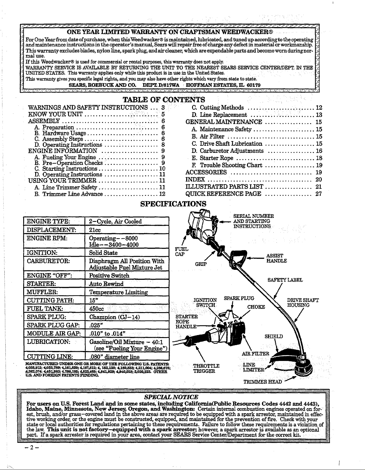
SPECIFICATIONS
2-Cycte, Air Cooled
DISPLACEMENT:
:ENGINE RPM:
IGNITION:
CARBURETOR:
ENGINE "OFF":
STARTER:
MUFFLER:
CUTTING PATH:
FUEL TANI_
21cc
Operating- -8000
Idle--3400-4000
Solid State
]
Diaphragm-- All Posi_on With
Adjustable Fuel Mixture Jet
FUEL
CAP
GRIP
Positive Switch _
:Auto Rewind _ • .......11....
,,,,,, ......................................
Temperature IAmitin_
16" IGNITION SPARKPLUG DRIVE SHAFT
............ _ :' SWITCH i _ CHOKE HOUSING
SPARK PLUG:
SPARK PLUG G.AP: .025" HANDLE-----_
SERIAL NUMBER
l_---AND STARTING
INSTRUCTIONS
SAFETYLABEL
MODULE AIR GAP: .010" to .014 _ .: .!;........ __ SHIELD
LUBRICATION: : '""Gasoline/Off _e - 40il _\ ....
CL_TING LINE: .080"diameterline _ AIRFILTER • : ,
............................................ , :? :
_¢UFACrwmD tri_lm01_oRMOREOF_ FOL_OW_ US.I,A_ THROTTLE '::?_F_,R4,0_,,91_,,,1,0$2,9_, 4,1sl,s_, 4,1_,812; 4, _3,1_; 4,1em,e_; 4_1:t,004: 4,,_,6_; : : ,
_62,0"/4; 4,4gL98S; 4,2_8_ZS5; 4,823,4_; 4,84_2_, 4,940,02.8; 5,020,._z_ OI'HER 'r_I__x_ : , , : , . t::., '
US. AND FOREIGN PATENTS PENDING. _R HEAD' _ ........
(see"FuelingYo_ Engine') tt
_ SPECIAL NOTICE I_
_[ For users on U.S. Forest Landand in some states,:includmg C_llfornia(Pt_li¢ Resources Codes 4442 and 4443), [_
[_[ Idaho, Maine, Minnesota, New Jerse_ Oregon, and W_gton: Certain interna_ combustion engines operated on for- _
_] est, brush, and/or grass-coy .exedlaud "rathe above areas are required to be equipped with a spark arrestor, maintained in effec-
tS| five working orde_ or the engine must be constructed, equipped, and maintained for the prevention of fire. Check with your [_
state or local authorities forregulations pertaining to these requirements. Failureto follow these requirements isa violation of _
_ the !aw. This unit is not facto ry.-equipped with a spark arrestor;, however, a sp_arkarrestor is available as an optional H
_ part. Ifa spark _estor zsrequ_ed m your area, contact your _ Serwce Center/Department for the correct kit. :.... :
-2-
WARNIY GS AYWI)SAFETY INSTRUCTIONS
(See Additional Safety Instructions throughout this Manual)
A WARI_/ING - THIS POWER TOOL CANBE DANGEROUS? This unit can ¢anse serious
be followed to provide reasonable safety and efficiency in using this unit. The operator is responsible for
following the warnings and instructions in this manual and on the unit. Read the entire Operator's Manual
before assembling and using this unit! Restrict the use of this power tool to persons who read, understand and follow
the wanfings and instructions in this manual and on the unit.
i i !,, ii
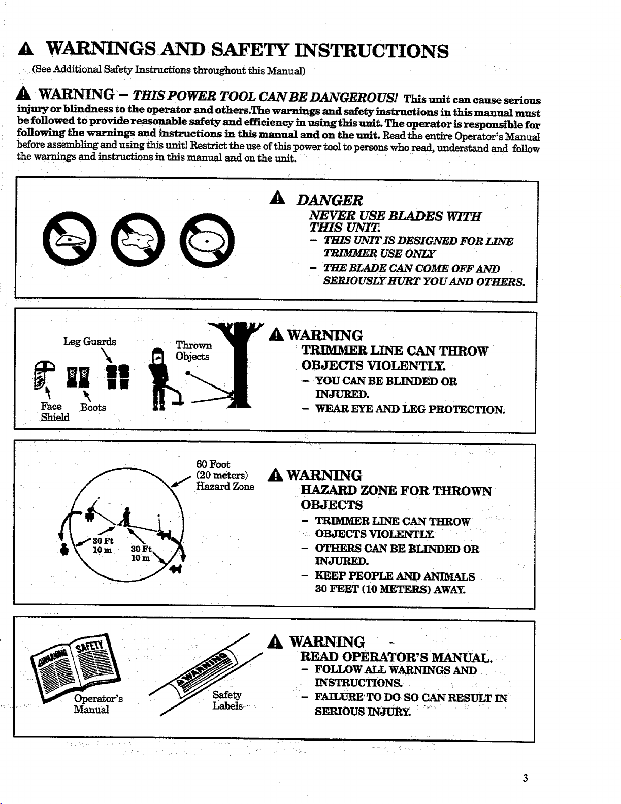
_k DANGER
NEVER USEBLADES WITH
THIS UNIT.
- THIS UNIT IS DESIGNED FOR LINE
TRIMMER USE ONLY
- THE BLADE CAN COME OFFAND
SERIOUSLY HURT YOU AND OTHERS.
AW_G
Leg Guards Thrown
, miW!
Face Boots
Shield
TRIMMER LINE CAN THROW
OBJECTS VIO_NTLY.
- YOU CAN BE BLINDED OR
INJURED.
- WEAR EYE AND LEG PROTECTION.
Operater's
Manual
6OFoot
(20 meters)
Hazard Zone
AkW_G
HAZARD ZONE FOR THROWN
OBJECTS
- TRIMMER LINE CAN THROW
OBJECTS VIOLENTLY.
- OTHERS CAN BE BLINDED OR
INJURED.
- KEEP PEOPLE AND ANIMALS
30 FEET (10 METERS) AWAY.
A WARNING .r
READ OPERATOR'S MANUAL.
- FOLLOW ALL WARNINGS AND
INSTRUCTIONS.
- FAILURE'TO DO SO CAN RESULT IN
SERIOUS_IN_. ".....
i , ,
. E. •
3

WARNINGS AND SAFETY INSTRUCTIONS....(Continued)
_k OPERATOR SAFETY
1. Always wear eye protection when operating, serv-
icing, or performing maintenance on your unit.
See '_ccessories."
2. Always wear heavy, long pants, boots, and gloves.
Do not go barefoot or wear short pants, sandals,
jewelry, loose clothing, or clothing with loosely
hanging straps, ties, tassels,::: etc; they cau: be
.... caught in moving parts. Secure hair so it is above
sho_der length. Being fully covered will help pro-
tect you from pieces of toxic plants such as poison
ivy thrown by the trimmer line, which could be
more of a hazard than touching the plant itself.
3. Do not operate this unit when you are tired, ill, or
under the influence of alcohol, drugs, or medica-
tion.
4. Wear hearing protection if you use this unit for
more than 1-1/2 hours per day.
5. Never start or run the en_e inside a closed room
or building. Breathing exhaust fumes can kill.
6. Keep t_ndles free of,off and fuel.
A TOOL SAFETY
1. Inspect entire unit before each use. Replace dam-
2. Replace trimmer head parts that are cr_ked,
chipped, broken, or damagedin any other waybe-
fore using the unit.
3. Use only .080" diameter SEARS Laser Line_.
Never use wire, rope, string etc.
4. Install the shield properly before using the unit.
5. Use only the specked trimmer head. Make sure
the trimmer head is properly installed and se-
curely fastened. Refer to '_kssemb]y."
6. Make carburetor adjustments with the drive shaft
housing supported to prevent the trimmer line
from contacting any object. Hold the unit by hand;
do not use the optional shoulder strap for support.
7. Keep others away when making carburetor ad-
justments.
8. Use only genuine SEARS accessories as recom-
mended for this unit.
A FUEL SAFETY
1. Mix and pour fuel outdoors and where there are
no sparks or flames.
2. Use a container approved for fuel
3. De not smoke or allow smoking near fuel or the
unit or while using the unit.
4. Wipe up all fuel spills before starting engine.
5. Move at least 10 feet (3 meters)away from fueling
site before Starting engine.
6. Stop engine before removing fuel cap.
7. Empty the fuel tank before storing the unit. Use
up fuel left in the carburetor and fuel lines by
stertingthe engine and lettingit run until it stops.
8. Store unit and fuel in an area where fuel vapors
cannot reach sparks or open flames from water
heaters, electric motors or switches, furnaces, etc.
A CUTTING SAFETY
1. Inspect the area to be cut before each use. Remove
objects (rocks, broken glass, nails, wire, string,
etc.) which can be thrown or become entangled in
the trimmer head.
2. Keep others including children, animals, bystand -
ers and helpers outside the 60 foot (20 meter) Haz-
ard Zone. Step the engine immediatebyifyou are
approached.
3. Always keep the engine on the right-hand side of
your body.
4. Hold the unit firmly with both hands.
5. Keep firm footing and balance. Do not over-
reach.
6. Keep the trhnmer head below waist level.
7. Do not raise the engine above your:waist. The
trimer head can come dangerously close to your
body.
8. Keep all parts of your body away from trimmer
head and muffler when engine is running.
9. When possible, cut with the left side of the trim-
_ met head.
10. Use only for jobs explained in this manual.
SAFETY
1. the unit accordingto recommended pro-
icedures. Keep the cutting line at the proper
length.
2. Disconnect the spark plug before_performing
maintenance except for carburetor adjustments.
3. Make carburetor adjustments with the drive shaft
housing supported to prevent the trimmer Iin_e i
from contacting any object. Hold the unit by
hand; do not use the optional shoulder strap for
support.
4. Keep others away when making carburetor ad-
justments.
5. Use only genuine SEARS replacement parts as
recommende& ,....
A TRANSPORTING AND STORAGE
1. Hand cerry the unit with the engine stopped and
the muffler away from your body.
2. Allow the engine to cool, empty the fuel tau_ and
secure the unit before storing or transporting in a
vehicle.
3. Empty the fuel tank before storing the unit_ Use
up fuel left in the carburetor by starting the en-
gine and lett_g the engine run until it stops.
4. Store unit and fueLin an area Where fuel vapors
cannot reach sparks or open flames from water
heaters, electric motors or switct_es, furnaces, etc.
5. Store umt so line _ter cannot accidentally
cause injury. The unit can be hung by the drive
sha_housing. '
6. Store the unit out of the reach of children.
..... Contact your Authorized Service Dealer if you need assistance.
If situ_tions occur which are not covered in this manual, use care and good judgment.
IIII I I.... illI IIII i I II l IIIIII " _i
IIIII IIIIIIIIIII IIIIII II IIIIIII I
KNOW YOUR UNIT
IIIII II I
A. INTRODUCTION
and sweeping.
Special Features Include:
• 15" Cutting Path
• Semi-Automatic Trimmer Head
• Adjustable Assist Handle
• 21cc Engine
B. UNPACKING INSTRUCTIONS
1. Afterremoving the contentsfrom the c_ton,
checkpartsagainstthe CartonContentslist.
2. Examine the partsfordamage. Do not use
damaged parts.
3. Notify your SFARS Service Center!Depart-
me_ immediately if apart is missing or dam-
agea. •
NOTE: It is normal to hear the fuel filter rattle in
an empty fuel tenk.
IIIIIIIII IIIIII III III I I
I IIIIIIIIII II I • I III_IIIUlil1/
IIII I III I1[ I lU IIIII lUmlllI
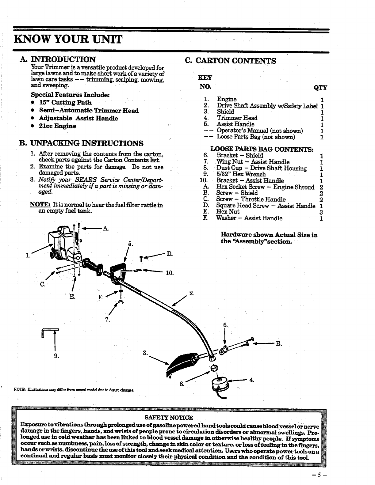
C. CARTON CONTENTS
¸¸KEY
NO. QTY
1. Engine 1
2. Drive Stmi_ Assembly w/Safety Label 1
3. Shield 1
4. Trhnmer Head 1
5. Assist Handle 1
-- Operator's Manual (not shown) 1
-- Loose Parts Bag (not shown) 1
LOOSE PARTS BAG CONTENTS:
.
Bracket - Shield 1
7.
Wing Nut - Assist Handle 1
8.
Dust Cup - Drive Shaft Housing 1
9.
5/32" Hex Wrench " 1
10.
Bracket - Assist Handle 1
Hex Socket Screw - Engine Shroud 2
B.
Screw- Shield 2
C.
Screw - Throttle Handle 2
D.
Square Head Screw - Assist Handle t
E.
Hex Nut 3
E
Washer - Assist Handle 1
E. E
Hardware shown Actual Size in
the "Assembly'section_
10°
SAFETY NOTICE H
Exposu_ to vibrations throughprolonged use of gasoline powered hand tools could_ bl_d v_l er n_e
H dam_. em the fi_ez, s, _l_a._, and w_" s of people prone to circuIah'on disorder, or abnormal __. _ i_
_] occur such _num. oness, pa_._ loss of ..s_. ngth, change m skin color or texture, or loss of feeling in the fingers, [_
nanas or wrm_ msconuuue rne use of this tool and seekmedical attention. Users who operate power tools on a
ntinual and regular basis must monitor closely their physical condition and the condition of this tool. [_
-5-
ASSEMBLY
(If tool is received assembled, repeat all steps in this section to be sure assembly is correct and is ad-
justed for the operator.)
A. PREPARATION
This Operator's Manual is designed to help you as-
semble the tool and to provide its safe operation. It is
important that you read the entire manual to become
familiarwiththetoolbeforeyou beginassembly.
1. Read your Operator's Manual
2. Tools you will need:
- 5/32" Hex Wrench provided with the tool.
- AdjustableWrench
- Standard Screwdriver
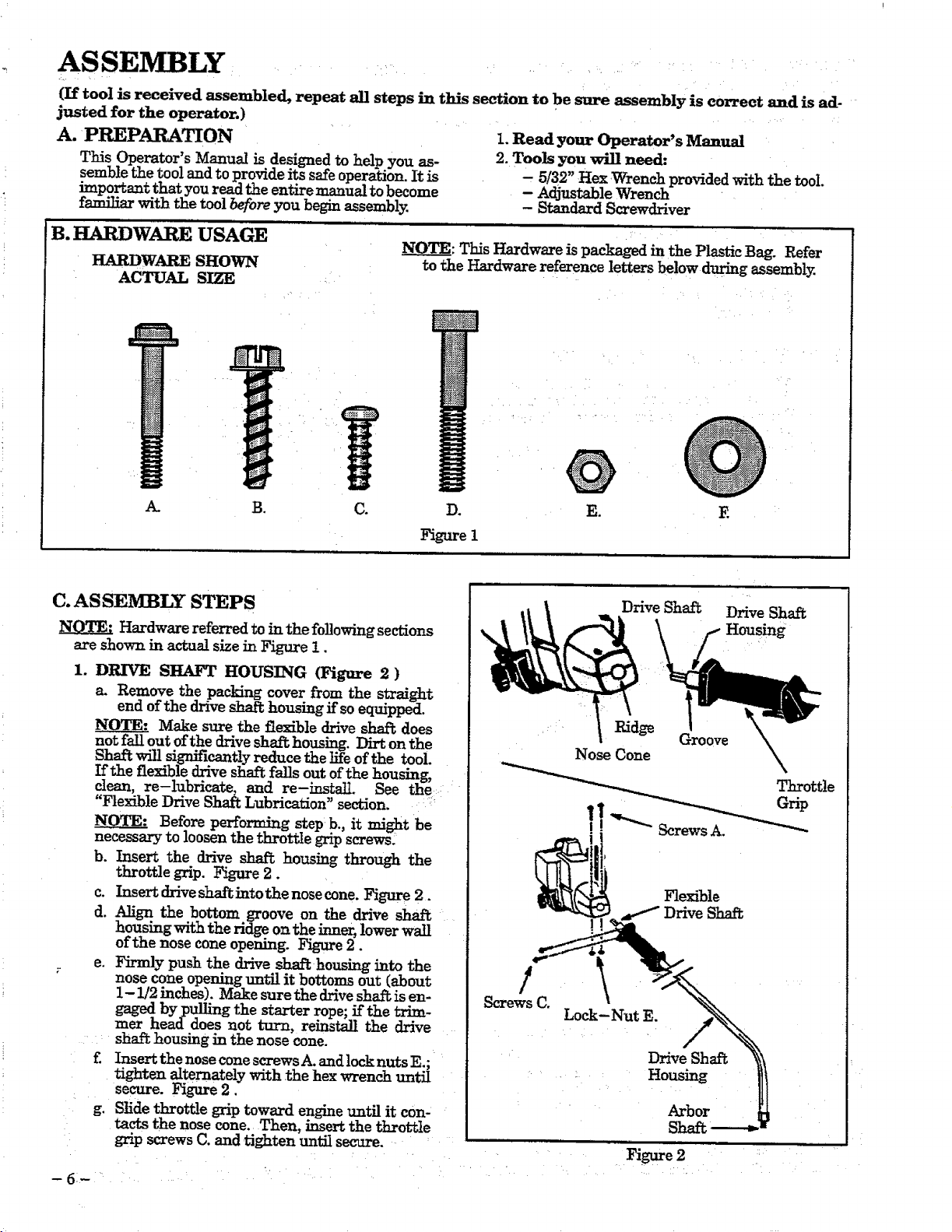
B. HARDWARE USAGE
HARDWARE SHOWN
ACTUAL SIZE
A. B. C.
C. AS SEMBLY STEPS
NOTE: Hardware referred to in the following sections
are shown in actual size in Figure 1.
1. DRIVE SHAFT HOUSING (Figure 2 )
a. Remove the packing cover from the straight
end of the drive shaft housing if so equipped.
Make sure the flexible drive shal_ does
not fall out of the drive shaft housing. Dirt on the
Shaft will significantly reduce the life of the tool.
If the flexible drive sh_ falls out of the housing,
,clean'- re-lubricate,, and re-mstalI." See the:
Flexible Drive Shaft Lubrication _ section. ?
NOTE: Before performing step b., it might be
necessary to loosen the throttle grip screws/
b. Insert the drive shaft housing through the
throttle grip. Figure 2.
c. Insert drive shaft into the nose cone. Figure 2.
d. Align the bottom groove on the drive shaft
housing with the ridge on the inner, lower wall
of the nose cone opening. Figure 2.
e. Firmly push the drive shaft housing into the
nose cone opening unt_ it bottoms out (about
1-1/2 inches). Make sure the drive shaft; is en-
gaged by pulling the starter rope; if the trim-
mer head does not turn, reinstall the drive
sha_ housing in the nose cone.
£ Insert the nose cone screws.4- andlock nuts E.;
tighten alternately with the hex wrench until
secure. Figure 2.
g. Slide throttle grip toward engine until it con-
tacts the nose cone. Then, _ert the throttle
grip screws C. and =tighten until secure.
NOQ__T_:This Hardware is packaged in the Plastic Bag. Refer
to the Hardware reference letters below during assembly.
@
E
f- Housing
Groove k
Throttle
Flexible
Drive Shaft
D_
Figure I
@
E.
l _ Drive Shaft Drive Shaft
Nose Cone X
"1
!
Screws C.
Lock-Nut E.
DriveShal%
Shaft
- 6- • ....
.? •
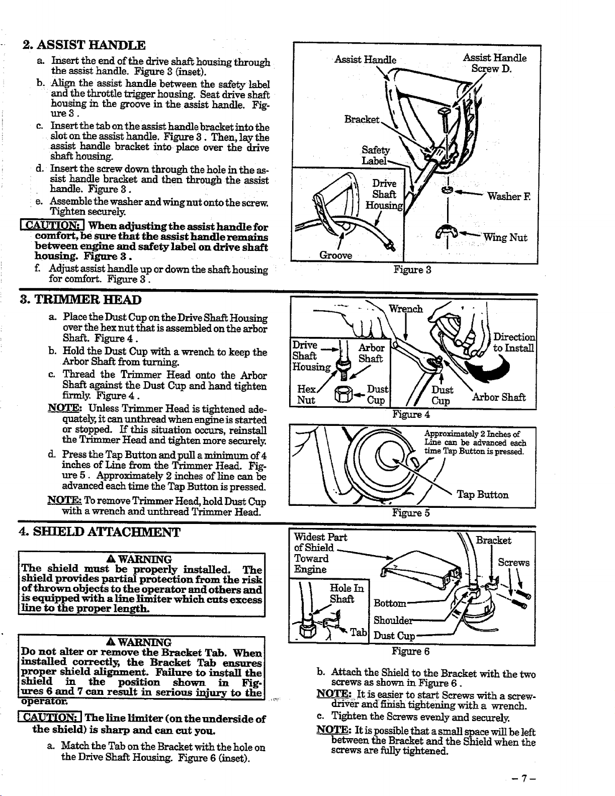
2. AS SIST HAI'w-D_
a. Insert the end of the drive shaft housing through
the assist handle. Figure 3 (inset).
b. Align the assist handle between the safety !_el
:and the throttle trigger housing. Seat drive shaft
housing in the groove in the assist handle. Fig-
ure3.
Insert the tab on the assist handle bracket into the
slot oil the assist handle. Figure 3. Then, lay the
assist handle bracket into place over the drive
shaft housing.
d. Insert the screw down through the hole in the as-
sist handle bracket and then through the assist
handle. Figare 3.
e. Assemble the washer andwingnut onto the screw.
Tighten securely.
Assist Handle
Assist Handle
• Screw D.
Washer E
between engine and safety label on drive shaft
housing. Figure 3.
Z .Adjustassisthandle up or down the sha_ housing
for comfort. Figure 3.
TRIMMER , , ,m ,,,,,,, ,
3. HEAD
a. Place the Dust Cup on the Drive Shaft Housing
over the hex nut that is assembled on the arbor
Shaft. Figure 4.
b. Hold the Dust Cup with a wrench to keep the
Arbor Shaft from turning.
c. Thread the Trimmer Head onto the Arbor
Shaft against the Dust Cup and hand tighten
firmly. Figure4.
NOTE: Unless Trimmer Head is tightened ade-
quately, it can unthread when engine is started
or stopped. If this situation occurs, reinstall
the Trimmer Head and tighten more securely.
d. Press the Tap Button and pull a minimum of 4
inches of Line from the Trimmer Head. Fig-
ure 5. Approximately 2 inches of line can be
advanced each time the Tap Button is pressed.
To remove Trimmer Head, hold Dust Cup
with a wrench and unthread Trimmer Head.
4. SHIELD ATTACHMENT
I A WARNING I
IThe shield must be properly installed. Thel
Ishield provides partial protection from the riskI
Iof thrown objects to the operator and others and I
!is equipped with a line limiter which cuts excess I
!1.Lneto the proper length. !
Groove
Direction
to Install
Nut Cup Arbor Shaft
Figure 4
Buttonis pressed.
Tap Button
Figure 5
, i ,,, ,,,,,, ,
Widest Part Bracket
ofShield-_
Toward _ Screws
Engine
a WARNmQ ..........I
Do not alter or remove the Bracket Tab. Whenl
installed correctly; the Bracket Tab ensures l
proper shield _llgnment. Failure to ins.tall the l
shield in the position shown m Fig-I
ures 6 and 7 can result in serious injury to the I
opera, or.
The line limiter (on the underside of
the shield) is sharp and can cut you.
a. Match theTab ontheBracketwiththehole on
the Drive Shaft Housing. Figure6 (inset).
Figure6
b. Attach the Shield to the Bracket with the two
screws as shown in Figure 6.
_TE; !t is easier to start Screws with a screw-
dxivel- and_sh tightening with a wrench.
c. Tighten the Screws evenly and securely.
It is possible that a small space will be left
en the Bracket and the Shield when the
screws are fully tightened.
-7-
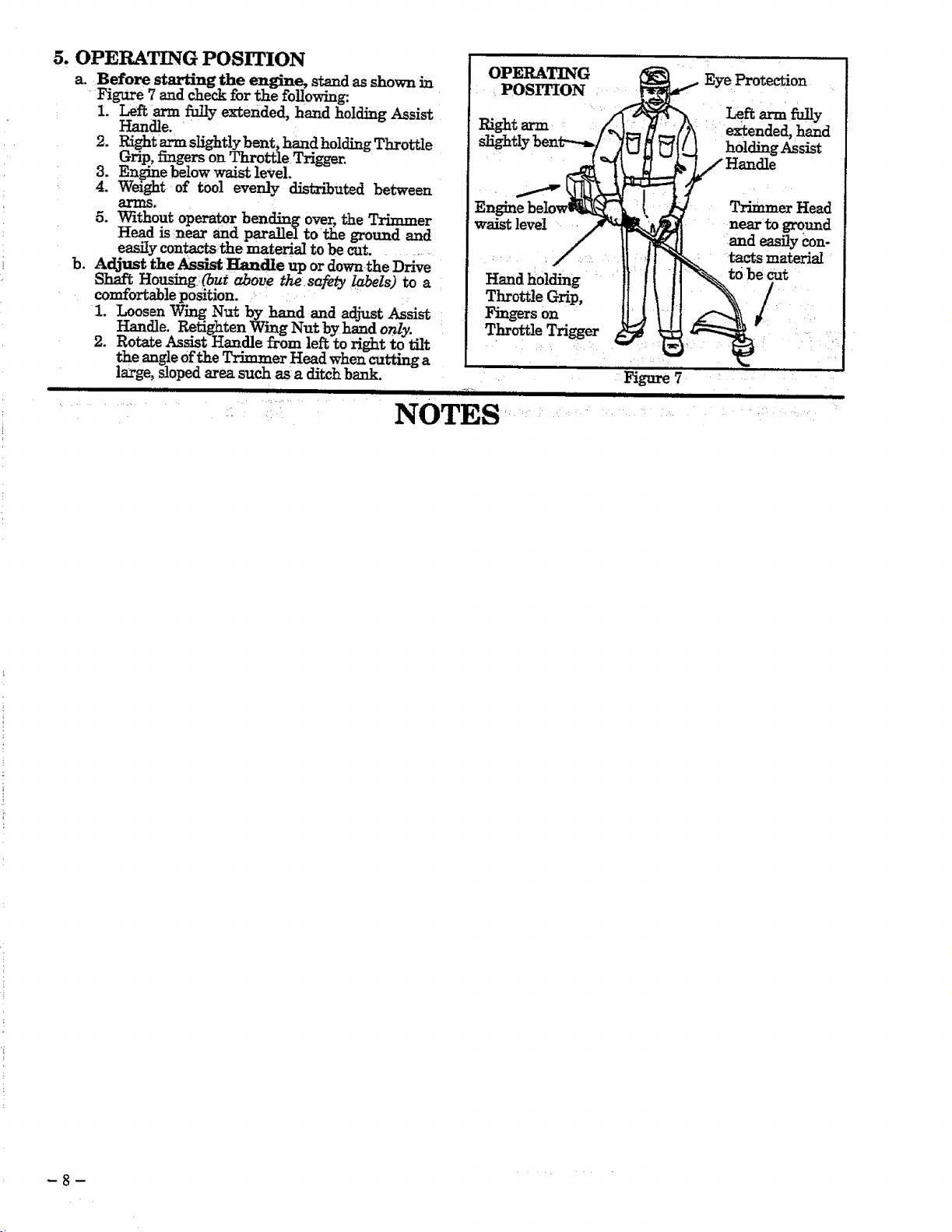
5. OPERATING POSITION
a. Before starting the engine, stand as shown in
_Figure 7 and check for the following:
: I. Lef_ arm fully extended, hand holding Assist
Handle. _
2. Right arm slightlybent, hand holding Throttle
Grip, fingers on Throttle Trigger.
3. Engine below waist level.
4. Weight of tool evenly distributed between
arms.
5. Without operator bending over, the Trimmer
Head isnear and parallel torthe ground and
easily contactsthe material to be cot ..........
b. Adjust the Assist _dle up or down.the Drive
Shaft Housing(but above thesafety labels) to a
comfortable position.
1. Loosen Wing Nut by hand and adjust Assist
Handle. Retighten Wing Nut by hand o_/y.
2. Rotate Assist Handle from lef_ to right to tilt
the augle of the Trimmer Head when _atting a
large, sloped area such as a ditch bank.
i iiiml,iiIHI i i i
NOTES
OPERATING
POSITION
waist level
Haud holding
Throttle Grip,
Fingers on
Throttle Trigger
Eye Protection
extended, hand
holding Assist
Trimmer Head
near to gruund
and easily con-
tacts material
to be cut
/
Figure 7
-8-
ENGINE INFORMATION
A. FUELING YOUR ENGINE
1.FUEL SAFETY
a. Use only recommended fuel mixtures.
b. Mix and pour fuel outdoors and where
there are no sparks or flames.
c. Use a container approved for fuel.
d. Do not smoke or allow smoking near fuel
•or the unit or while using the unit.
e. Wipe up all fuel spills before starting the
engine.
£ Move at least 10 feet (3 meters) away
from fueling site before starting engine.
g. Stop engine before removing fuel cap.
Allow engine to cool before refueling.
h. Before storing the unit, use up fuel left in
..... the fuel lines and carburetor by starting the
engine and letting it _.Jn until it stops.
i. Store unit and fuel m an area where fuel
vapors cannot reach sparks or open
flames from water heaters, electric motors or
switches, furnaces, etc.
2. FUEL MIXTURE
e. Your unit is powered by a 2-cycle engine
which requires a fuel mixture of regular
unleaded gas?!ine and a high quality en-
gine oil spemally made for 2-cycle, air
cooled engines. The internal design of the
2-cycle engine requires lubrication of moving
parts. Lubrication is provided when the rec-
ommended mixture of gasoline and oil is used.
b. Genuine Sears 40:1, 2-cycle engine oil is
strongly recommended for the protection
of your unit. Extensive englneeringtests have
proven that Sears 2-cycle engine oil resists
break-down at operating temperatures com-
mon to 2-cycle engines, resulting in depend-
able performance and longer engine life.
c. Gasoline must be clean and not over two
months old. After a short period of time,
gasoline wilt chemically break down and form
compounds thatcausehard starting and dam-
i age m 2-cycle engines.
d. The correct measure of gasoline to oil is
very important. Too much oil in the mixture
will foul the spark plug.
_ Too little oil or incorrect oil
_iwill cause engine to overheat and seize.
e_i:_Always mi_ the fuel thoroughly in a con-
: ii tainer since gasoline and oil do not readily
::: combine. Do not mix gasoline and oil directly
: ::: :in t_ _l _k" r
3. USE THE FOLLOWING:
SEARS CRAFTSMAN 2-cycle engine oil _ed
at 40:1 is strongly recommended_ Consult the
instructions on oil container for proper mixing.
1 PART OIL TO 40 PARTS GASOLINE=
3.2 ft. oz. oil to i gallon gasoline
8.0 ft. oz. oil to 2.5 gallon gasoline
Not all air cooled 2-cycle engine oils have the
same qualities. If SEARS CRAFI'SMAN
2-_cle engine_ oil is not available, use a good
quality, 2-cycle engine oil recommended for
air-cooled engines. Mix at a ratio of 16:1 (8 oz.
oil to I gallon gasoline). A 16:1 fuet mixture with
these oils will assure adequate lubrication for
.....yourengine.
4. DO NOT USE:
• NMM Oil--National Marine Manufac-
turers Association (formerly BIA oil)--
• AUTOMOTIVE OIL--
Does not have proper additives for air-cooled0
2-cycle engines and can cause engine damage.
..... A CAUTION
Experience indicates that alcohol blended fuels
(tailed gasohol or using ethanol or methanol)
can attract moisturewhich leads to separation
and formation of acids during storage. Acidic
gas can damage the fuel system of an engine
while in storage. To avoid engine problems, do
not leave fuel in the unit when storing for 30
days or longer. Start the engineand let it run
until the fuel lines and carburetor are empty.
Use fresh fuel next season. See the "Storage"
section for additional information. Never use
engine or carburetor cleaner products in the
fuel tank or permanent damage can occur.
5. HOW TO MIX FIlL AND FILL TANK
a.: Pour the proper measure of engine oil into an
approved, marked container. Then, flU the
container with regular unleaded gasoline.
NOTE: If fuel is alreadyin the container, add the
::, :: proper measure of engine oil. Then, close the
container tightly and shake it momentarily.
NOTE: Do not mix gasoline and oil directly in the
:: fuel tank.
b. Using a spout or funnel, fill the fuel tank with
.... fuel mix.
c. 1_ the fuel caps securely.
B. PRE-OPERATION CHECKS e. Use only the specified trimmer head. See
.......................................... ..... "Specifications." Make sure the trimmer head is
I A WARNING _ , [ • properly installed and securely fastened. Refer to
]Review all Warnings and Safety Instructions ml _Assembly. _ -_
Ithismanual. ! f. Make carburetor adjustments with the
1. Before operating y.our unit, always:
Inspect the entire unit before each use. Re-
place damaged parts. Check for fuel leaks and
make sure all fasteners are in place and securely
fastened. .....
b. Replace trimmer head parts that are
cracked, chipped, broken, or damaged in
any other way before using the unit.
c. Use only .080" diameter Sears Laser Line.
Never use wire, rope, string, etc_
d. Use only with the shield properly attached.
drive shaft housing supported to prevent
trimmer line from contacting any object. Hold
unit by hand; do not use optional shoulder strap
for support.
g,
Keep others away when making carburetor
adjustments.
h.
Use only genuine Sears accessories or attach-
ments recommended for this unit.
i.
Clean air filter if dirty before operating
unit. Refer to "Specifications, _ for air filter loca-
tion.
 Loading...