

Craftsman 358798470 Owner’s Manual
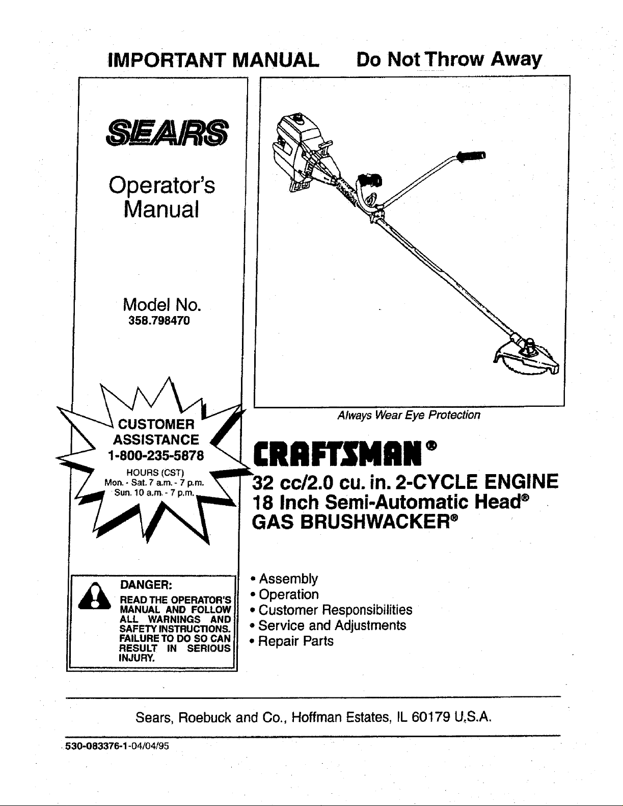
IMPORTANT MANUAL Do Not Throw Away
Operator's
Manual
Model No.
358.798470
CUSTOMER
ASSISTANCE
1-800-235-5878
DANGER:
READ THE OPERATOR'S
MANUAL AND FOLLOW
ALL WARNINGS AND
SAFETY INSTRUCTIONS.
FAILURE TO DO SO CAN
RESULT IN SERIOUS
INJURY.
Always Wear Eye Protection
®
cc/2.0 cu. in. 2-CYCLE ENGINE
18 Inch Semi-Automatic Head®
GAS BRUSHWACKER®
• Assembly
° Operation
• Customer Responsibilities
° Service and Adjustments
° Repair Parts
Sears, Roebuck and Co., Hoffman Estates, IL 60179 U_S.A.
530.083376-1-04/04/95
ii i tIJL
SAFETY RULES
cAUT|oNI ALWAYS D SCONNECT SPARK PLUG RE A........ I Wl ND PLACE WIRE WHERE IT CANNOT
CONTACT SPARK PLUGTO PREVENTACCIDENTALSTARTING WHEN SETTING UP, TRANSPORTING,
ADJUSTING OR MAKING REPAIRS.
OPERATOR SAFETY
• Alwayswear safetyeye protection,
• Always wear longpants, tong sleeves,bootsand
gloves.Wearing safety leg guardsis recom-
mended. Do notgo barefoot or wear sandals,
shortpants, shortsleeves.Beingfully covered
heJpsto protectyou from piecescf toxicplants
thrownby the bladeor cuttinghead.
• Secure hair so it is above shoulderlength. Secure
looseclothingorjewelry, or clothingwithloosely
hangingties, straps,tassels,etc.;theycan be
caught in movingparts.
• Do not operatethisunitwhen youare tired,it!,or
underthe influenceof alcohol,drugs,ormedica-
tion.
• Wear hearing protectionifyou usethisunitfor
more than 1-1/2 hoursper day.
• Never startor run the engine insideaclosed
roomor building. Breathingexhaustfumes can
kill.
• Keep handlesfree of oil and fuel
• Alwaysuse the handlebarand a properlyadjusted
shoulderharness.
• If situationsoccurwhich are notcoveredinthis
manual, usecare and good judgement.
UNIT MAINTENANCE/SAFETY
• Lookfor and replacedamaged or loosepartsbe-
fore each use. Lookfor and repairfue!leaksbe-
fore use. Keep theunit in goodworkingcondi-
lion.
° Throw away bladesthat are bent,warped,
cracked, broken,or damaged inany otherway.
• Replace trimmer head parts that arechipped,
cracked, broken,ordamaged inany otherway
beforeusing theunit.
° Use only .080" diameter monofilamentline.
Never use wire, rope,string, etc.
• Keep the blade sharpand thecuttinglineat the
properlength.
• Make sure the unitis maintainedand assembled
correctlyas listedinthis manual.
• Installthe requiredshield properlybefore using
the unit. Use themetal blade shieldfor blades_
and the plasticlinetrimmer shieldfor linetrimmer
use.
• Use only the specifiedbladeor trimmerhead.
• Be sure blade ortrimmerhead stopsturning
when engine idles,
• Make carburetoradjustmentswiththelowerend
supportedto preventthe blade ortrimmerline
from contactingany object. Hold unitby hand;do
not useshoulderharnessfor support.
• Keep othersaway when makingcarburetorad-
justments.
I SAFETY'NOTICE . .............
JExposure to vibrations through prolonged use of gasoline powered hand toots could cause blood vessel or nerve damage in the
I fingers, hands, and joints of people prone to circulation disorders or abnormal swel|ings. Prolonged use in cold weather haS been
| linked to blood vessel damage in otherwise healthy people. If symptoms occur such as numbness, pain, loss of strength, change
] in skin color or texture, or loss of feeling in the fingers, hands or joints, discontinue the use of this unit and seek medical a_en-
Itton. An anti-vibration system does not guarantee the avoidance of these problems. Users who operate power tools on a continu-
I al and regular basis must monitor closely their physical condition and the condition of this unit.
• Use only goodquality SEARS accessories and
replacement parts as recommended for this unit.
• Have air maintenance and service not explained
in this manual performed by your SEARS Service
Center.
FUEL SAFETY
• Mix and pourfue! outdoors.
• Keep away fromsparks orflames.
• Use a containerapproved for fuel.
• Do not smoke or allow smokingnear fuel orthe
unitor whileusingthe unit.
• Wipe up all fuel spillsbefore startingengine.
• Move at least 10 feet (3 meters) away from fuel-
ingsite beforestarlingengine.
• Stop engine and allow the engine tocool before
removingfuel cap.
CUTTING SAFETY
• Inspectthe area to be cutbefore each use. Re-
moveobjects (rocks,broken glass,nails,wire,
string,etc.) whichcan be thrownor become en-
tangled in the blade ortdmmer head.
• Keep others includingchildren, animals, bystand-
ers and helpers at least 50 feet (15 meters) away.
Stop the engine immediately if youare
approached.
• Always keep the engineon the right-hand side of
yourbody.
• Hold the unitfirmly with both hands.
• Keep firm footing and balance. Do not over-
reach.
• Keep the blade or trimmerhead below waist level.
• Do not raise the engine above yourwaist.
• Keep all partsof your bodyaway from the blade
or trimmerhead and muffler when engine is run-
ning.
• Cut from your right to your left.
• Use only for jobs explained in this manual.
TRANSPORTING AND STORAGE
° Stop the unitbeforetransporting.
• Allowthe engine tocool, and secure the unit be-
fore storingor transportingin a vehicle.
• Emptythe fuel tank before storingor transporting
the unit. Use up any fuel left inthe carburetor by
startingthe engineand lettingthe engine rununtil
it stops.
• Store unitand fuel inan area where fuel vapors
cannotreach sparksor open flames from water
heaters,electric motors or switches,furnaces,
etc.
• Store unitso the blade or line fimiter cannot acci-
dentallycause injury.
• Store the unitout of the reach of children.
I
IT MEANS - AI"FENTIONtll BECOME ALERTllf YOUR SAFETY IS INVOLVED.
LOOK FOR THIS SYMBOL TO POINT OUT IMPORTANT SAFETY PRECAUTIONS.
"2-
SAFETY RULES
DANGER
THIS POWER UNIT CAN BE DANGEROUS! THIS UNIT CAN CAUSE SERIOUS INJURY OR BLINDNESS TO THE
OPERATOR AND OTHERS, THE WARNINGS AND SAFETY INSTRUCTIONS IN THIS MANUAL MUST BE FOL-
LOWED TO PROVIDE REASONABLE SAFETYAND EFFICIENCY IN USING THIS UNIT. THE OPERATOR IS RE-
SPONSIBLE FOR FOLLOWING THE WARNINGSAND INSTRUCTIONS IN THISMANUALAND ON THE UNIT.READ
THEENTIRE OPERATOR'S MANUALBEFOREASSEMBLING AND USING THISUNIT! RESTRICT THE USE OF THIS
POWER UNIT TO PERSONS WHO READ, UNDERSTAND AND FOLLOW THEWARNINGSAND INSTRUCTIONS IN
THIS MANUAL AND ON THE UNIT. NEVER ALLOW CHILDREN TO USE THISTOOL.
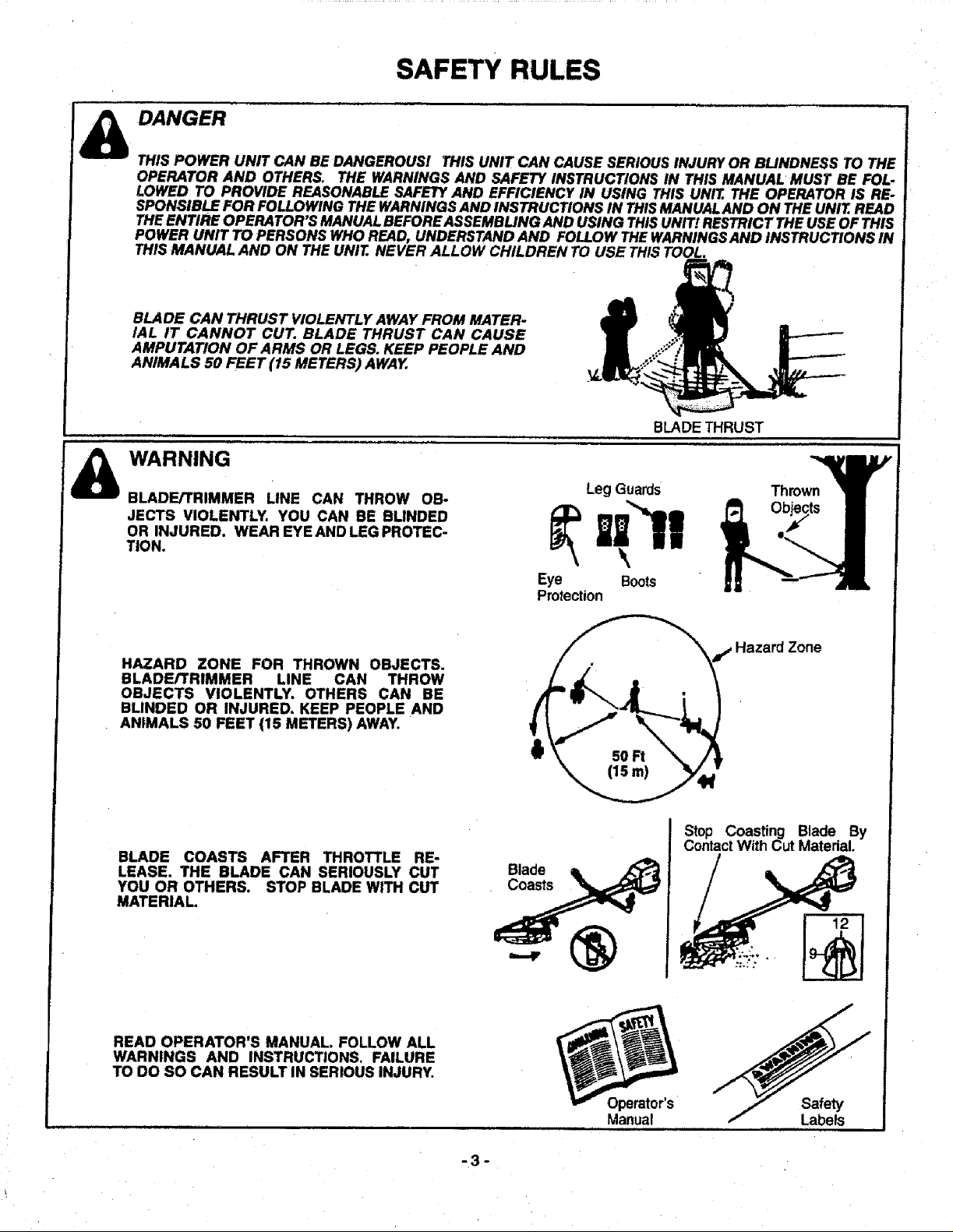
BLADE CAN THRUST VIOLENTLY AWAY FROM MATER-
IAL IT CANNOT CUT. BLADE THRUST CAN CAUSE
AMPUTATION OF ARMS OR LEGS. KEEP PEOPLE AND
ANIMALS 50 FEET (15 METERS) AWAY.
BLADE THRUST
WARNING
BLADE/TRIMMER LINE CAN THROW OB-
JECTS VIOLENTLY. YOU CAN BE BLINDED
OR INJURED. WEAR EYE AND LEG PROTEC-
TION.
HAZARD ZONE FOR THROWN OBJECTS.
BLADE/TRIMMER LINE CAN THROW
OBJECTS VIOLENTLY. OTHERS CAN BE
BLINDED OR INJURED, KEEP PEOPLE AND
ANIMALS 50 FEET (15 METERS) AWAY.
BLADE COASTS AFTER THROTTLE RE-
LEASE. THE BLADE CAN SERIOUSLY CUT
YOU OR OTHERS. STOP BLADE WITH CUT
MATERIAL.
Eye Boots
Protection
Blade
Coasts
Leg Guards
Thrown
ird Zone
Stop Coasting Blade By
ContactWith Cut Material.
READ OPERATOR'S MANUAL. FOLLOW ALL
WARNINGS AND INSTRUCTIONS. FAILURE
TO DO SO CAN RESULT IN SERIOUS INJURY.
-3-
Manual
Safety
Labels
ill
CONGRATULATIONS on your purchase of a Sears
Craftsman Brushwacker. It has been designed,
engineered and manufactured to give you the best
possibledependability and performance.
Should you experience any problems you cannot easily
remedy, please contact your nearest Sears Service
Center/Department. Sears has competent, well trained
technicians and the proper tools to service or repair this
unil.
Please read and retain this manual. The instructions will
enable you to assemble and maintain your unit property.
Always observe the "SAFETY RULES."
MODEL NUMBER: 358.798470
DATE CODE/SERIAL NO.:
DATE OF PURCHASE:
THE MODEL AND SERIAL NUMBER WILL BE
FOUND ON THE PRODUCT.
YOU SHOULD RECORD BOTH SERIAL NUMBER
AND DATE OF PURCHASE AND KEEP IN A SAFE
PLACE FOR FUTURE REFERENCE.
MAINTENANCE AGREEMENT
A Sears Maintenance Agreement is available on this
product. Contact your nearest Sears Store for detaiIs.
CUSTOMER RESPONSIBILITIES
• Read and observe thesafety rules.
• Follow a regular schedule in maintaining,caring for,
and using your unit.
• Follow the instructionsunder"CustomerResponsibilities"
and "Storage" sectionsofthisOperator'sManual.
PRODUCT SPECIFICATIONS
,, ,,, ,,,,
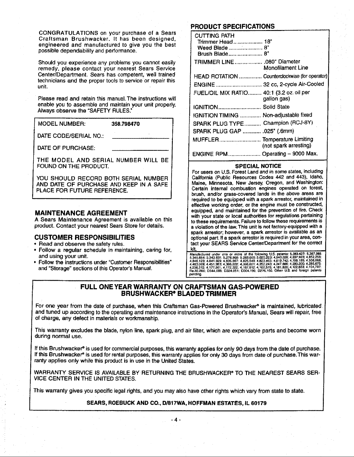
CUTTING PATH
Trimmer Head ................... 18"
Weed Blade........_............. 8"
Brush Blade ...................... 8"
TRIMMER LINE ................... 080" Diameter
Monofilament Line
HEAD ROTATION ............... Counterclockwise(foroperator)
ENGINE .............................. 32 cc, 2-cycle Air-Cooled
FUEL/OIL MIX RATIO ......... 40:1 (3.2 oz. oilper
gallon gas)
iGNITION ............................ Solid State
IGNITION TIMING .............. Non-adjustable fixed
SPARK PLUG TYPE ........... Champion (RCJ-8Y)
SPARK PLUG GAP ............. 025" (.6mm)
MUFFLER ........................... Temperature Limiting
(not spark arresting)
ENGINE RPM ..................... Operating - 9000 Max.
SPECIAL NOTICE
ForusersonU.S.ForestLandandinsomestates,including
California (Public ResourcesCodes442 and443), Idaho,
Maine, Minnesota,New Jersey,Oregon,and Washington:
Certain internalcombustionengines operatedon forest,
brush, and/or grass-covered lands in theaboveareasare
required to beequipped witha spark arrestor,maintainedin
effectiveworkingorder,orIhe enginemustbeconstructed,
equipped, and maintainedforthe prevention of fire.Check
withyourstateor localauthoritiesfor regulationspertaining
totheserequirements. Failuretofollowtheserequirements is
a violationofthe taw.Thisunitisnotfactory=equipped witha
sparkarrestor;however,a sparkarrestorisavailableasan
optionalpart.ffa sparkarrestoris requiredinyourarea,con-
tactyourSEARS ServiceCentedDepartmentfor thecorrect
kit.
Manufactured under one or more _f the following U,S, patet_ls: 5,_,427: 5.367,988:
5,345.684; 5,343_831; 5.276.968: 5,269.665; 5.G_0,L_23: 4,940,028: 4,697,923: 4,852,258:
4,846,123; 4,84 t,929; 4.835,867; 4,825.548; 4,823,465; 4,819,742; 4,798,185: 4,508,068;
4,483,069; 4,451,983: 4,366,622:4.366.62114.352,243; 4,347,666: 4,L_0,200; 4.286,675;
4,236.312; 4,177,_61 ; 4,172.322; 4.167,812; 4,!62,575; 4,161,820; 4,122.653: 4,104,797:
Re,32.266; D344,088; D324.051: 1_304.196; 0276,!60. Other U,S. and foreign patents
periling.
FULL ONE YEAR WARRANTY ON CRAFTSMAN GAS-POWERED
BRUSHWACKER e BLADED TRIMMER
For one year from the date of purchase, when this Craftsman Gas-Powered Brushwacker_ is maintained, lubricated
and tuned up according to the operating and maintenance instructions in the Operator's Manual, Sears willrepair, free
of charge, any defect in materials or workmanship.
This warranty excludes the blade, nylon line, spark plug, and air filter,whichare expendable parts and become worn
during normal use.
If this Brushwacke_' is used forcommercialpurposes,thiswarrantyapplies foronly 90 days from the date of pumhase.
If this Brushwacket _ is used for rental purposes, this warranty applies for only 30 days from date of purchase.This war-
rant',/applies only while this product is in use in the United States.
WARRANTY SERVICE IS AVAILABLE BY RETURNING THE BRUSHWACKEFP TO THE NEAREST SEARS SER-
VICE CENTER IN THE UNITED STATES.
This warranty gives you specificlegal rights, and you may also have otherrights which vary from state to state.
SEARS, ROEBUCK AND CO., D/817WA, HOFFMAN ESTATES, IL 60179
-4-
,, ,,,,,,,,,, ,,, i

TABLE OF CONTENTS
Safety Rules .................................................................... 2
Product Specifications ................ :..................................... 4
Warranty .......................................................................... 4
Accessories ..................................................................... 5
Assembly ......................................................................... 7
Operation ...................................................................... 12
A
Accessories...,,................................................................ 5
Adjustments
Carburetor .................................................................. 29
Handlebar .................................................................. 17
Idle Speed....................................... ........................... 29
Line Advance ............................................................. 17
Air Filter......................................................................... 22
Assembly
Blades ............................................................... 10 & 11
Semi-automatic Head .................................................. 9
Handlebar .................................................................... 8
Metal Debris Shield ................................................... 10
Plastic Debris Shield .................................................... 8
Throttle Handle ............................................................ 9
B
Blade Sharpening ......................................................... 28
Blade Thrust.................................................................. 14
C
Carburetor Adjustments ................................................ 29
Carton Contents .............................................................. 6
Customer Assistance
Hotline................................. ;........................... Back Cover
Customer Responsibilities ............................................. 21
CuttingMethods
Trimmer Operating Tips ............................................. 20
Blade Operating Tips ................................................. 15
D
Drive Shaft Lubrication .................................................. 22
E
Engine
Fuel/Oil....................................................................... 18
Spark Plug................................................................... 4
Starting ...................................................................... t 9
Storage ...................................................................... 30
Customer Responsibilities ............................................. 21
Service and Adjustments .............................................. 24
Storage.......................................................................... 30
Trouble Shooting ........................................................... 31
Repair Parts Ordering/Service ....................... Back Cover
INDEX
F
Fue!ing .......................................................................... 18
Fue! Filter ...................................................................... 23
H
Handlebar .............................................................. _........:8
K
Know Your Brushwacker ................................................ 12
L
Line Advancement ........................................................ 17
Line Replacement ......................................................... 26
M
Maintenance Schedule ....i............................................ 21
Model Number................................................................. 4
O
Operation
Brushwacker .............................................................. 18
Line Trimmer .............................................................. 20
Ordering Repair Parts .................................... Back Cover
R
Repair Parts List ........................................................... 32
S
Service and Adjustments.............................................. 24
Specifications.................................................................. 4
Starter Rope .................................................................. 24
Starting.......................................................................... 19
Storage.......................................................................... 30
T
Throttle Handle ................................................................ 9
Trouble Shooting .......................................................... 31
W
Warranty .......................................................................... 4
ACCESSORIES
These accessories and attachments' Were available when the unit was originallypurchased.They are also availableat
mostSears retail outletsand service centers.Most Searsstorescan orderthese items foryouwhen youprovidethemodel
number of your unit.
Accessories
,,,,,,,,,,,,,,,
GAS
CAN
SAFETY
GOGGLES
2-CYCLE
ENGINE OIL
3.2 OZ.
40:1
,,, _ ,,,i ,
SPARK SEMI-
PLUG AUTOMATIC
HEAD
-5-
BULK
LINE
400 FT.
SPOOL WITH
LINE
SHOULDER
STRAP KIT
AIR
FILTER
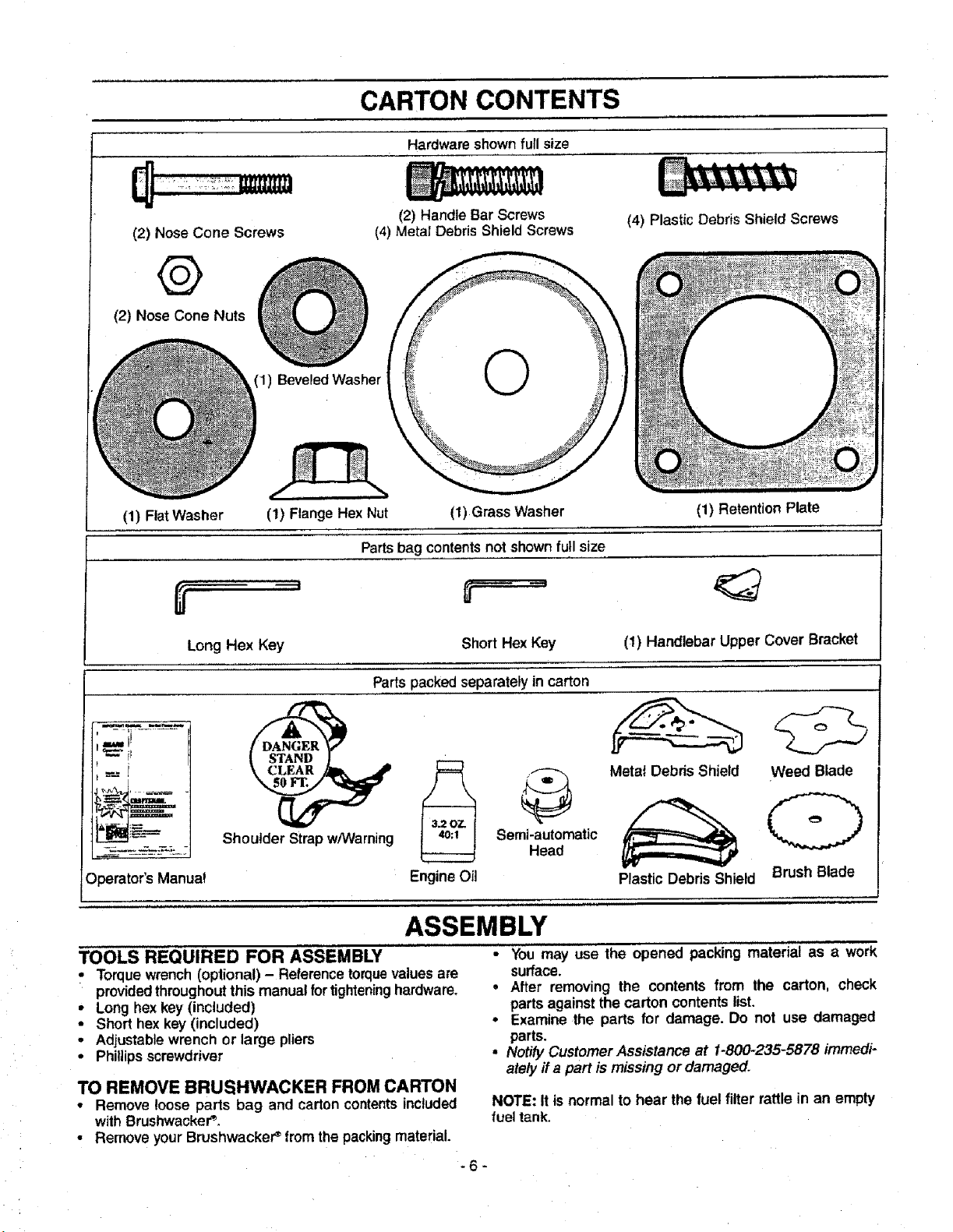
CARTON CONTENTS
Hardware shownfull size
(2) Nose Cone Screws
(2) Handle Bar Screws
(4) Metal Debris Shield Screws
(4) Plastic Debris Shield Screws
@
(2) Nose Cone Nuts
(1) BeveledWasher
(1) Flat Washer (1) Flange Hex Nut (1)Grass Washer (1) Retention Plate
Parts bag contents not shown full size
Long Hex Key Short Hex Key
(1) Handlebar Upper Cover Bracket
Partspacked separately in carton
;-il...........
!
Shoulder Strap w/Warning
Operator'sManua_ EngineOil
TOOLS REQUIRED FOR ASSEMBLY
• Torquewrench (optional) - Referencetorquevaluesare
providedthroughoutthis manual fortighteninghardware,
• Long hex key (included)
• Short hex key (included)
• Adjustablewrench or large pliers
• Phillipsscrewdriver
TO REMOVE BRUSHWACKER FROM CARTON
• Remove loose parts bag and carton contents included
with Brushwacker _
• Remove yourBrushwackeP from the packingmaterial.
_ Semi-i_Uta_dmatic
ASSEMBLY
Metat Debris Shield
Weed Blade
(D
Plastic Debris Shield
• You may use the opened packing material as a work
surface
° After removing the contents from the carton, check
parts againstthe carton contents list
• Examinethe parts for damage Do not use damaged
parts
• Notify Customer Assistance at 1-800-235-5878 immedi-
ately ffa part is missing or damaged
NOTE: It is normal to hear the fuel filter rattle in an empty
fueltank.
-6-
Brush Blade
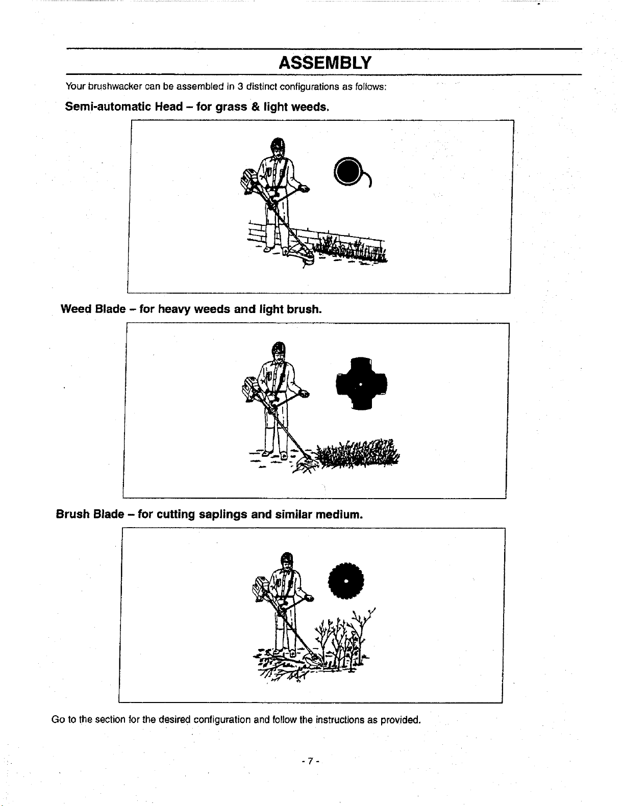
ASSEMBLY
Your brushwacker can be assembled in 3 distinct configurations as follows:
Semi-automatic Head - for grass & light weeds,
Weed Blade - for heavy weeds and light brush.
Brush Blade - for cutting saplings and similar medium.
Go to the section for the desired configuration and follow the instructionsas provided.
-7-
ASSEMBLY
HOW TO ASSEMBLE 'fOUR"
BRUSHWACKER
_ ARNING:
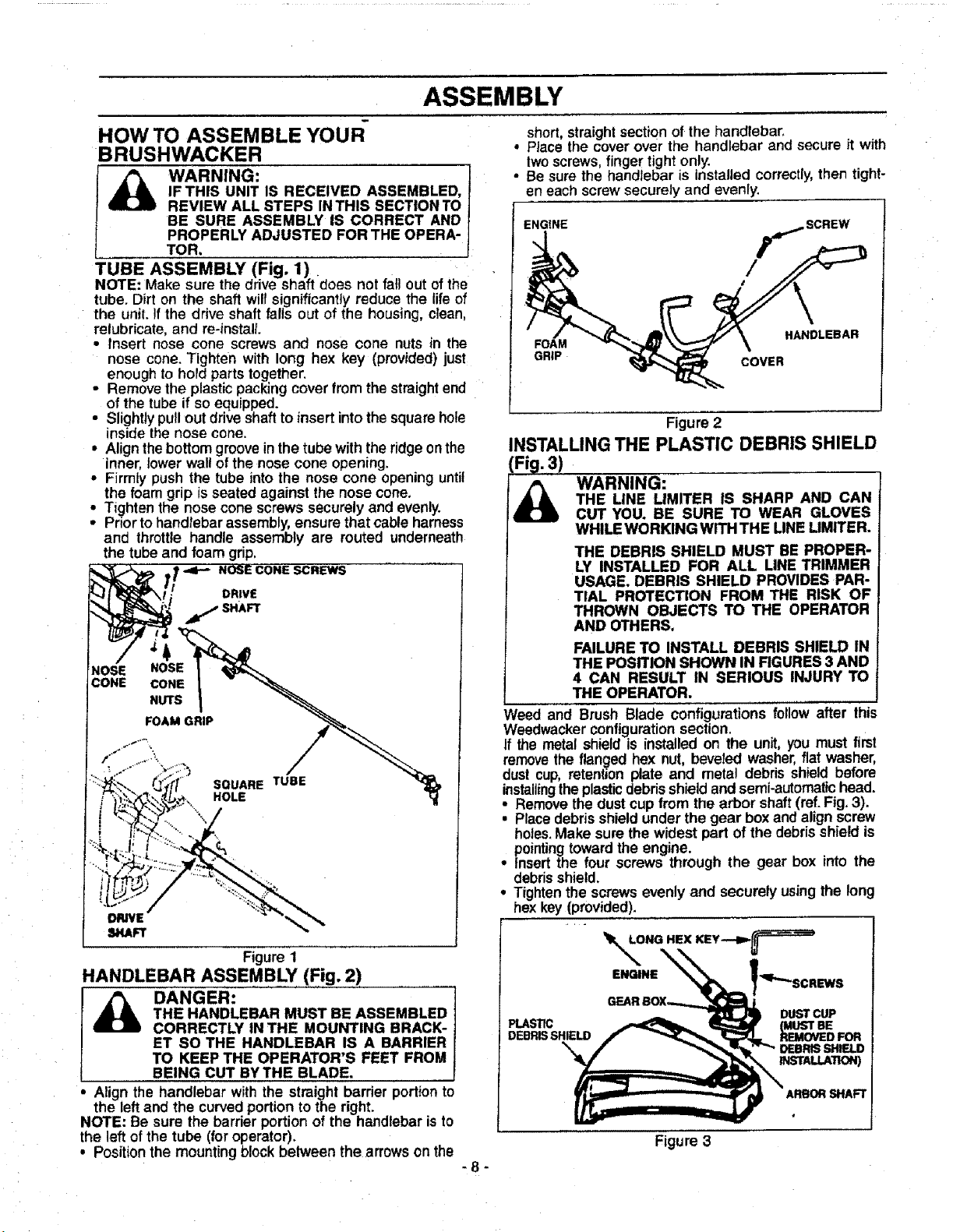
TUBE ASSEMBLY (Fig. I)
NOTE: Make sure the drive shaft does not fall out of the
tube. Dirt on the shaft will significantly reduce the life of
the unit. !fthe drive shaft fails out of the housing, clean,
relubricate, and re-instalL
• Insert nose cone screws and nose cone nuts in the
nose cone. Tighten with long hex key (provided) just
enough to hold parts together.
• Remove the plastic packing cover from the straightend
of the tube if so equipped.
• Slightly pull out drive shaft to insert into the square hole
inside the nose cone.
• Align the bottom groove in the tube withthe ridge on the
inner, lower wall of the nose cone opening.
• Firmly push the tube into the nose cone opening until
the foam grip isseated against the nose cone.
• Tighten the nose cone screws securely and evenly.
• Prior to handlebar assembly, ensure that cable harness
and throttle handle assembly are routed underneath
the tube and foam grip,
NOSE NOSE
CONE CONE
IF THIS UNIT IS RECEIVED ASSEMBLED,
REVIEW ALL STEPS IN THIS SECTION TO
BE SURE ASSEMBLY IS CORRECT AND
PROPERLY ADJUSTED FOR THE OPERA-
TOR,
NOSE CONE SCREWS
DRIVE
j SHAFT
NUTS
FOAM GRIP
short, straight section of the handlebar.
° Place the cover over the handlebar and secure it with
twoscrews, finger tight only.
• Be sure the handlebar is installed correctly, then tight-
en each screw securely and evenly.
ENGINE
SCREW
FOAM HANDLEBAR
GRIP COVER
Figure 2
INSTALLING THE PLASTIC DEBRIS SHIELD
_ ARNING:
Weed and Brush Blade configurations follow after this
Weedwacker configurationsection.
If the metal shield is installed on the unit, you must first
remove the flan_ed hex nut, beveled washer, flat washer,
dust cup, retenbon plate and metal debris shield before
installingthe plastic debris shield and semi-automatic head.
o
Remove the dust cup from the arbor shaft (ref. Fig. 3).
• Place debris shield under the gear box and align screw
holes. Make sure the widest part of the debris shield is
pointing toward the engine.
• Insert the four screws through the gear box into the
debris shield.
° Tighten the screws evenly and securely using the long
hex key (provided).
THE LINE LIMITER IS SHARP AND CAN
CUT YOU. BE SURE TO WEAR GLOVES
WHILE WORKING WITH THE LINE LIMtTER.
THE DEBRIS SHIELD MUST BE PROPER-
LY INSTALLED FOR ALL LINE TRIMMER
USAGE. DEBRIS SHIELD PROVIDES PAR-
TIAL PROTECTION FROM THE RISK OF
THROWN OBJECTS TO THE OPERATOR
AND OTHERS.
FAILURE TO INSTALL DEBRIS SHIELD IN
THE POSITION SHOWN IN FIGURES 3 AND
4 CAN RESULT IN SERIOUS INJURY TO
THE OPERATOR.
Figure 1
HANDLEBAR ASSEMBLY (Fig. 2)
i_ DANGER:
Align the handlebar with the straight barrier portion to
the left and the curved portion to the right.
NOTE: Be sure the barrier portion of the handlebar is to
the left of the tube (for operator).
, Position the mounting block between the arrows on the
THE HANDLEBAR MUST BE ASSEMBLED
CORRECTLY IN THE MOUNTING BRACK-
ET SO THE HANDLEBAR IS A BARRIER
TO KEEP THE OPERATOR'S FEET FROM
BEING CUT BYTHE BLADE.
-8-
r-
ENGINE
PLASTIC (MUST BE
DEBRISSHIELD REMOVED FOR
"_ DEBRIS SHIELD
Figure 3
DUST CUP
INSTALLATION)
ARBOR SHAFT
ASSEMBLY
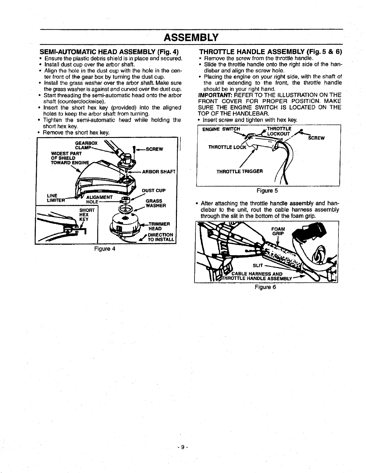
SEMI-AUTOMATIC HEAD ASSEMBLY (Fig. 4)
• Ensure the plasticdebrisshieldisin place and secured.
• Installdust cup overthe arbor shaft.
• Align the hole in the dust cup withthe hole in the cen-
ter front of the gear box by turning the dust cup.
• Installthe grass washer over the arbor shaft. Make sure
the grass washer is against and curved over the dust cup.
• Start threading thesemi-automatic head onto the arbor
shaft (counterclockwise).
• Insert the short hex key (provided) into the aligned
holes to keep the arbor shaft from turning.
• Tighten the semi-automatic head while holding the
short hex key.
• Remove the short hex key.
GEARBOX
WIDEST PART
OF SHIELD
THROTTLE HANDLE ASSEMBLY (Fig. 5 & 6)
• Remove the screwfrom the throttle handle.
• Slide the throttlehandle onto the rightside ofthe han-
dlebar and align the screw hole.
• Placing the engine on your right side, with the shaft of
the unit extending to the front, the throttle handle
should be in your right hand,
IMPORTANT: REFER TO THE ILLUSTRATION ON THE
FRONT COVER FOR PROPER POSITION. MAKE
SURE THE ENGINE SWITCH IS LOCATED ON THE
TOP OF THE HANDLEBAR.
• Insert screw and tighten with hex key.
ENGINE SWITCH THROT'rLE
SCREW
THROTTLE
THRO'FrLE TRIGGER
Figure 5
• After attaching the throttle handle assembly and han-
dlebar to the unit, rout the cable harness assembly
through the slit in the bottom of the foam grip.
FOAM
GRIP
ABLE HARNESS AND
HANDLE ASSEMBLY
Figure 6
-9-
ASSEMBLY
I I iii
BRUSHWACKER CONFIGURATION
Assembly information for Weedwacker configuration is
located before this section, the Brush Blade configura-
tion follows after thissection.
DANGER:
THE METAL SHIELD MUST BE PROPERLY
INSTALLED ON THE TOOL ANYTIME THE
TOOL IS USED WITH THE BLADE. THE
FORWARD TIP ON THE METAL SHIELD
HELPS TO REDUCE THE OCCURRENCEOF
BLADE THRUST WHICH CAN CAUSE
SERIOUS INJURY SUCH AS AMPUTATION
TOTHEOPERATORORBYSTANDERS.
FAILURETO INSTALLTHE DEBRIS SHIELD
IN THE POSITION SHOWNCAN RESULT IN
SERIOUSINJURYTO THE OPERATOR.THE
LENGTHOF THE DEBRISSHIELD MUST BE
ALIGNEDWRH THE LENGTHOF THE DRIVE
SHAFTHOUSING.
THE BLADEIS SHARP ANDCAN CUT YOU.
BE SURE TO WEAR GLOVES WHILE
WORKING WITH BLADES
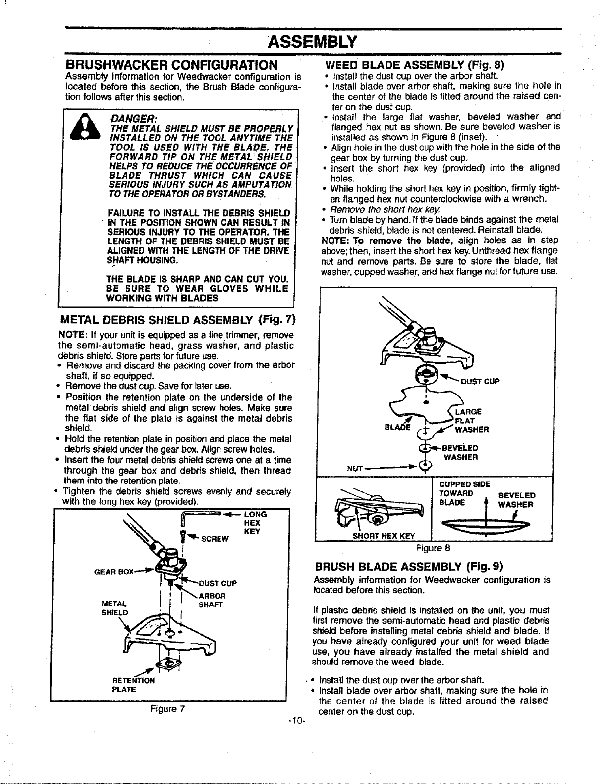
METAL DEBRIS SHIELD ASSEMBLY (Fig. 7)
NOTE: If your unitis equippedas a line trimmer,remove
the semi-automatic head, grass washer, and plastic
debris shield.Storepartsfor future use.
• Remove and discardthe packingcoverfrom the arbor
shaft, if so equipped_
• Remove the dustcup.Save for later use.
• Position the retention plate on the underside of the
metal debris shield and align screw holes. Make sure
the flat side of the plate is against the metal debris
shield.
• Hold the retentionplate in positionand place the metal
debrisshield underthegear box. Alignscrewholes.
• Insert the four metaldebdsshield screwsone at a time
through the gear box and debris shield, then thread
them intothe retentionplate,
• Tighten the debris shield screws evenly and securely
with the long hex key (provided),
ii ii i iiiiIIIH
WEED BLADE ASSEMBLY (Fig. 8)
• Installthe dust cup overthe arbor shaft.
• Install blade over arbor shaft, making sure the hole in
the center of the blade is fitted around the raised cen-
ter on the dust cup.
• Install the large flat washer, beveled washer and
flanged hex nut as shown. Be sure beveled washer is
installed as shown in Figure 8 (inset).
• Align hole in the dust cupwith the holein the side of the
gear box by turningthe dust cup.
• insert the short hex key (provided) into the aligned
holes.
• While holding the short hex key in position, firmly tight-
en flanged hex nutcounterclockwisewith a wrench.
• Remove the short hex key.
• Turnblade by hand. ft the blade binds against the metal
debris shield, blade is not centered. Reinstall blade.
NOTE: To remove the blade, align holes as in step
above;then, insert the short hex key. Unthread hex flange
nut and remove parts. Be sure to store the blade, flat
washer,cupped washer, and hex flange nutfor future use.
T CUP
_.. _ __ FLAT
BLADE _ _4_I"WASHER
NUT-- _ _
Ji _ i,J , . L,. LI
%LARGE
_1- BEVELED
(_";) WASHER
CUPPED SIDE
TOWARD BEVELED
_'q_ SCREW KEY
GEAR
_I_'_DUST CUP
METAL I SHAFT
SHIELD _
RETENTION
PLATE
i I _-*" ARBOR
Figure 7
HEX
SHORT HEX KEY
Figure 8
BRUSH BLADE ASSEMBLY (Fig. 9)
Assembly informationfor Weedwacker configuration is
locatedbefore this section.
If plastic debris shield is installed on the unit, you must
first remove the semi-automatic head and plastic debris
shield before installing metal debris shield and blade. If
you have already configured your unit for weed blade
use, you have already installed the metal shield and
should remove the weed blade.
• Installthe dust cup overthe arbor shaft.
, Install blade over arbor shaft, making sure the hole in
the center of the blade is fitted around the raised
center on the dust cup.
-10-
ASSEMBLY
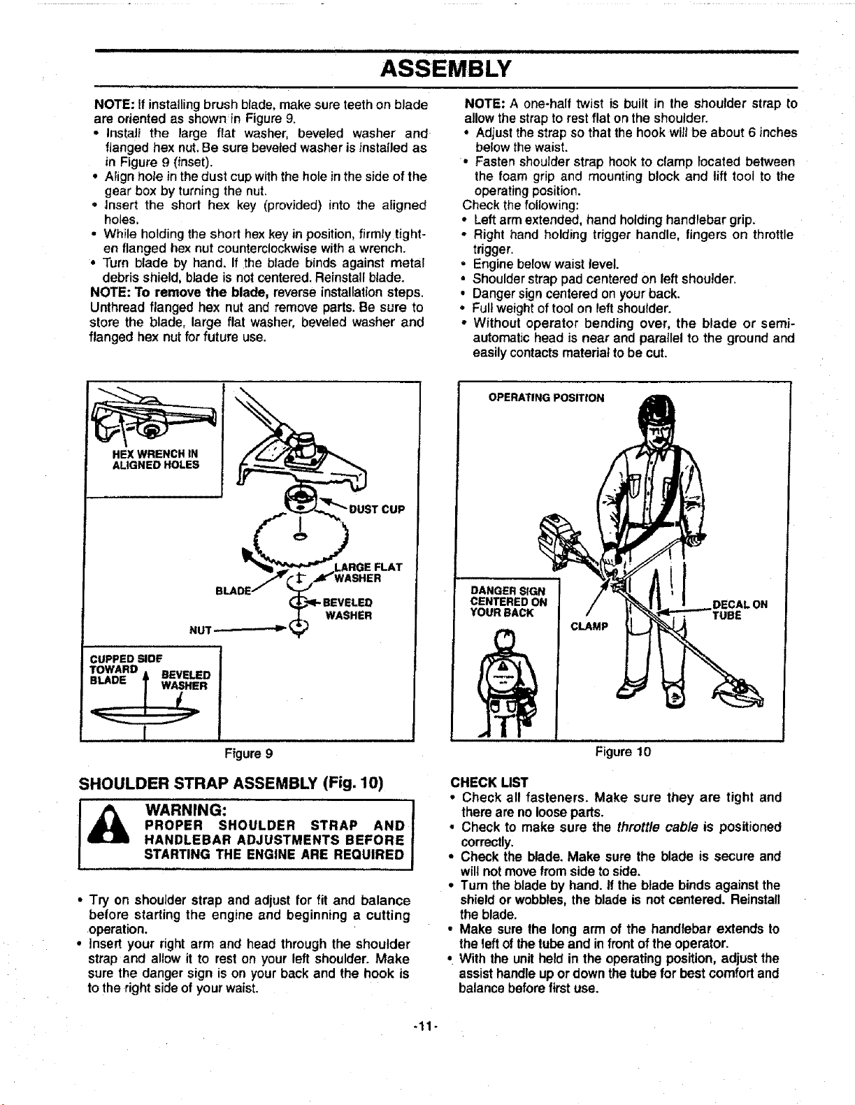
NOTE: If installing brush blade, make sure teeth on blade
are oriented as shownin Figure 9.
• Instal_ the large flat washer, beveled washer and
flanged hex nut. Be sure beveled washer is instaiJed as
in Figure 9 (inset).
• Aiign hole inthe dust cup withthe hole in the side of the
gear box by turning the nut.
° Insert the short hex key (provided) into the aligned
holes,
• While holding the short hex key in position,firmIy tight-
en flanged hex nut counterclockwise with a wrench.
° Turn blade by hand. If the blade binds against metal
debris shield, blade is not centered. Reinstall blade.
NOTE: To remove the blade, reverse installation steps.
Unthread flanged hex nut and remove parts. Be sure to
store the blade, large flat washer, beveled washer and
flanged hex nut for future use,
HEX WRENCH IN
ALIGNED HOLES
NOTE: A one-half twist is built in the shoulder strap to
allow the strap to rest flat on the shoulder.
° Adjust the strap so that the hook wilt be about 6 inches
below the waist.
• Fasten shoulder strap hook to clamp located between
the foam grip and mounting block and lift tool to the
operating position.
Check thefollowing:
• Left arm extended, hand holding handlebar grip.
• Right hand holding trigger handle, fingers on throttle
trigger.
• Engine below waist tevel.
• Shoulder strap pad centered on left shoulder.
• Danger sign centered on your back.
• Fullweight of tool on leftshoulder.
• Without operator bending over, the blade or semi-
automatic head is near and parallel to the ground and
easily contacts material to be cut.
OPERATING POSITroN
VASHER
WASHER
NUT _-
CUPPED SIDE
TOWARD
==1An= _ BEVELED
ii i
Figure 9
SHOULDER STRAP ASSEMBLY (Fig. 10)
PROPER SHOULDER STRAP AND 1
I_ WARNING: J
HANDLEBAR ADJUSTMENTS BEFORE !
STARTING THE ENGINE ARE REQUIRED J
• Try on shoulder strap and adjust for fit and balance
before starting the engine and beginning a cutting
operation.
• Insert your right arm and head through the shoulder
strap and allow it to reston your left shoulder. Make
sure the danger sign is on your back and the hook is
to the rightsideof your waist.
DANGER SIGN
CENTERED ON
YOUR BACK
CLAMP
DECALON
Figure 10
CHECK LIST
• Check all fasteners. Make sure they are tight and
there are no loose pads.
• Check to make sure the throttle cable is positioned
correctly.
° Check the blade. Make sure the blade is secure and
willnot movefromside to side.
° Turn the blade by hand. if the blade binds against the
shield or wobbles, the blade is not centered. Reinstall
the blade.
° Make sure the long arm of the handlebar extends to
the left of the tube and in front of the operator.
• With the unit held in the operating position, adjust the
assisthandle up or down the tube for best comfort and
balance before first use.
-11-
 Loading...