

Craftsman 358798461 Owner’s Manual

__S Operator's Manual
CRAFTSMRN
32cc 2-Cycle Engine
18 Inch Cutting Path / .080 In. Line
GASOLINE BRUSHWACKER _
Model No.
358.798461
Read and follow all Safety Rules and Operating
DANGER:
Instructions before first use of this product.
i_) For answers to your questions about this product:
Call 7 am-7 pm, Mon-Sat; Sun, 10 arn-7 pm
• 1-800-235-5878
Sears, Roebuck and Co., Hoffman Estates, IL 60179 USA
530-084336 05/06/96

Warranty Statement 2 Storage 17
Safety Rules 2 TroubleshootingChart 18
Assembly 5 Parts List 19
Operation 9
Maintenance 13 Spanish 22
Service & Adjustments 14 Parts and Ordering Back
FULL ONE YEAR WARRANTY ON CRAFTSMAN BRUSHWACKER ®
GAS POWERED BLADED TRIMMER.
For one year from the date of purchase, when this Craftsman Gas Powered
Brushwacker is maintained, lubricated, and tuned up according to the operating
and maintenance instructions in the Operator's Manual, Sears will repair, free of
charge, any defect il_ materials or workmanship.
This warranty excludes the blade, nylon line, spark plug, anci air filter, which are
expendable parts and become worn during normal use.
If this Brushwacker is used for commercial purposes, this warranty applies for only
90 days from the date of purchase. If this Brushwacker is used for rental purposes,
this warranty applies for only 30 days from the date of purchase. This warranty ap-
plies only while this product is in use in the United States.
WARRANTY SERVICE IS AVAILABLE BY RETURNING THE BRUSHWACKER'
TO THE NEAREST SEARS SERVICE CENTER IN THE UNITED STATES.
This warranty gives you specific legal rights, and you may also have other rights
which vary from state to state.
Sears, Roebuck and Co., D/817 WA Hoffman Estates, IL 60179
DANGER: This power tool can be
dangerous! This unit can cause serious
injuryincludingamputation or blindness
to the operator and others. The warn-
ings and safety instructionsin this man-
ual must be followed to provide reason-
able safety and efficiency in using the
unit.The operator is responsible for fol-
lowing the warnings and instructions in
this manual and on the unit. Read the
entire Operator's Manual before assem-
bling and using the unit! Restrict the use
of this unit to persons who read, under-
stand, and follow the wamings and in-
structionsin this manual and on the unit.
Never allow children to use this unit.
WarningDecal Z_
on Tube __f
WARNING: Follow all wamings and
instructions. Failure to do so can result
in serious injury.
SAFETY NOTICE
Exposure to vibrations through pro-
longed use of gasoline powered hand
tools could cause blood vessel or
nerve damage in the fingers, hands,
and joints of people prone to cimula-
tion disorders or abnormal swellings.
Prolonged use in cold weather has
been linked to blood vessel damage in
otherwise healthy people. If symptoms
occur such as numbness, pain, loss of
strength, change in skin color or tex-
ture, or loss of feeling in the fingers,
hands orjoints, discontinue the use of
this tool and seek medical attention.
An anti-vibration system does not
guarantee the avoidance of these
problems. Users Who operate power
tools on a continual and regular basis
must monitor closely their physical
condition and the condition of this tool.
2
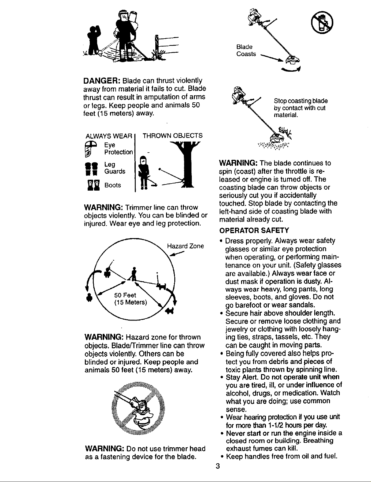
DANGER: Blade can thrust violently
away from material it fails to cut. Blade
thrust can result in amputation of arms
or legs. Keep people and animals 50
feet (15 meters) away.
®
Blade
Coasts
Stop coasting blade
by contact with cut
material.
ALWAYS WEAR
_ EyeProtection
THROWN OBJECTS
II Leg
II I Guards
_ Boots
WARNING: Trimmer line can throw
objects violently. You can be blinded or
injured. Wear eye and leg protection.
Hazard Zone
WARNING: Hazard zone for thrown
objects. Blade/Trimmer line can throw
objects violently. Others can be
blinded or injured. Keep people and
animals 50 feet (15 meters) away.
WARNING: Do not use trimmer head
as a fastening device for the blade.
WARNING: The blade continues to
spin (coast) after the throttle is re-
leased or engine is tumed off. The
coasting blade can throw objects or
seriously cut you if accidentally
touched. Stop blade by contacting the
left-hand side of coasting blade with
material already cut.
OPERATOR SAFETY
• Dress properly. Always wear safety
glasses or similar eye protection
when operating, or performing main-
tenance on your unit. (Safety glasses
are available.) Always wear face or
dust mask ifoperation is dusty. Al-
ways wear heavy, long pants, long
sleeves, boots, and gloves. Do not
go barefoot or wear sandals.
• Secure hair above shoulder length.
Secure or remove loose clothing and
jewelry or clothing with loosely hang-
ing ties, straps, tassels, etc. They
can be caught in moving parts.
• Being fully covered also helps pro-
tect you from debris and pieces of
toxic plants thrown by spinning line.
• Stay Alert. Do not operate unit when
you are tired, ill, or under influence of
alcohol, drugs, or medication. Watch
what you are doing; use common
sense.
• Wear hearing protectionif you use unit
for more than 1-1/2 hours per day.
• Never start or run the engine inside a
closed room or building. Breathing
exhaust fumes can kill.
• Keep handles free from oil and fuel.
3

° Always use the handlebar and a
properly adjusted shoulder strap with
a blade. See "Assembly."
UNIT/MAINTENANCE SAFETY
• Look for and replace damaged or
loose parts before each use. Look for
and repair fuel leaks before use. Keep
the unitin good working condition.
• Throw away blades that are bent,
warped, cracked, broken, or dam-
aged in any other way. Replace trim-
mer head parts that are cracked,
chipped, broken, or damaged in any
other way before using the unit.
• Maintain the unit according to recom-
mended procedures. Keep the blade
sharp. Keep the cutting line at the
proper length.
• Use only .080" (2 mm) diameter
Craftsman © Pro Trimmer brand line.
Never use wire, rope, string, etc.
• Installthe required shield properly be-
fore using the unit. Use the metal
shield for all metal blade use. Use the
plastic shield for all line trimmer use.
• Use only specified blade or trimmer
head; make sure it is properly in-
stalled and securely fastened.
• Never start engine with clutch shroud
removed. The clutch can fly off and
cause serious injury.
• Be sure blade or trimmer head stops
turning when engine idles.
• Disconnect the spark plug before
performing maintenance (except car-
buretor adjustments).
• Make carburetor adjustments with
the lower end supported to prevent
the blade or trimmer line from con-
tacting any object. Hold the unit by
hand; do not use the shoulder strap
for support.
• Keep others away when making car-
buretor adjustments.
• Use only recommended Sears ac-
cessories and replacement parts.
• Have all maintenance and service not
explained in this manual performed by
your Sears Service Center.
FUEL SAFETY
• Mix and pour fuel outdoors.
• Keep away from sparks or flames.
• Use a container approved for fuel.
• Do not smoke or allow smoking near
fuel or the unit or while using the unit.
• Wipe up all fuel spills before starting
engine.
• Move at least 10 feet (3 meters) away
from fueling site before starting engine.
• Stop engine and allow it to cool be-
fore removing fuel cap.
• Empty the fuel tank before storing
the unit. Use up fuel left in the carbu-
retor by starting the engine and let-
ting it run until it stops.
• Store unit and fuel in an area where
fuel vapors cannot reach sparks or
open flames from water heaters, elec-
tric motors or switches, furnaces, etc.
CUTTING SAFETY
• Inspect the area to be cut before
each use. Remove objects (rocks,
broken glass, nails, wire, string, etc.)
which can be thrown or become en-
tangled inthe blade or trimmer head.
• Keep others including children, ani-
mals, bystanders, and helpers at
least 50 feet (15 meters) away. Stop
the engine immediately if you are ap-
proached.
• Always keep engine on right-hand
side of your body.
• Hold the unit firmly with both hands.
• Keep firm footing and balance. Do
not overreach.
• Keep blade or trimmer head below
waist level.
• Do not raise the engine above your
waist.
• Keep all parts of your body away
from blade, trimmer head, and muf-
fler when engine is running.
• Cut from your right to your left.
• Use only for jobs explained in this
manual.
TRANSPORTING AND STORAGE
• Stop the unit before carrying.
• Keep muffler away from your body.
• Allow engine to cool and secure unit
before storing or transporting it in a
vehicle.
• Empty the fuel tank before storing or
transporting the unit. Use up fuel left
in the carburetor by starting the en-
gine and letting it run until it stops.
• Store unit and fuel in an area where
fuel vapors cannot reach sparks or
4
openflamesfromwaterheaters,elec-
tricmotorsor switches,fumaces,etc.
• Store unit so the blade or line limiter
cannot accidentally cause injury. The
unit can be hung by the tube.
• Store unit out of reach of children.
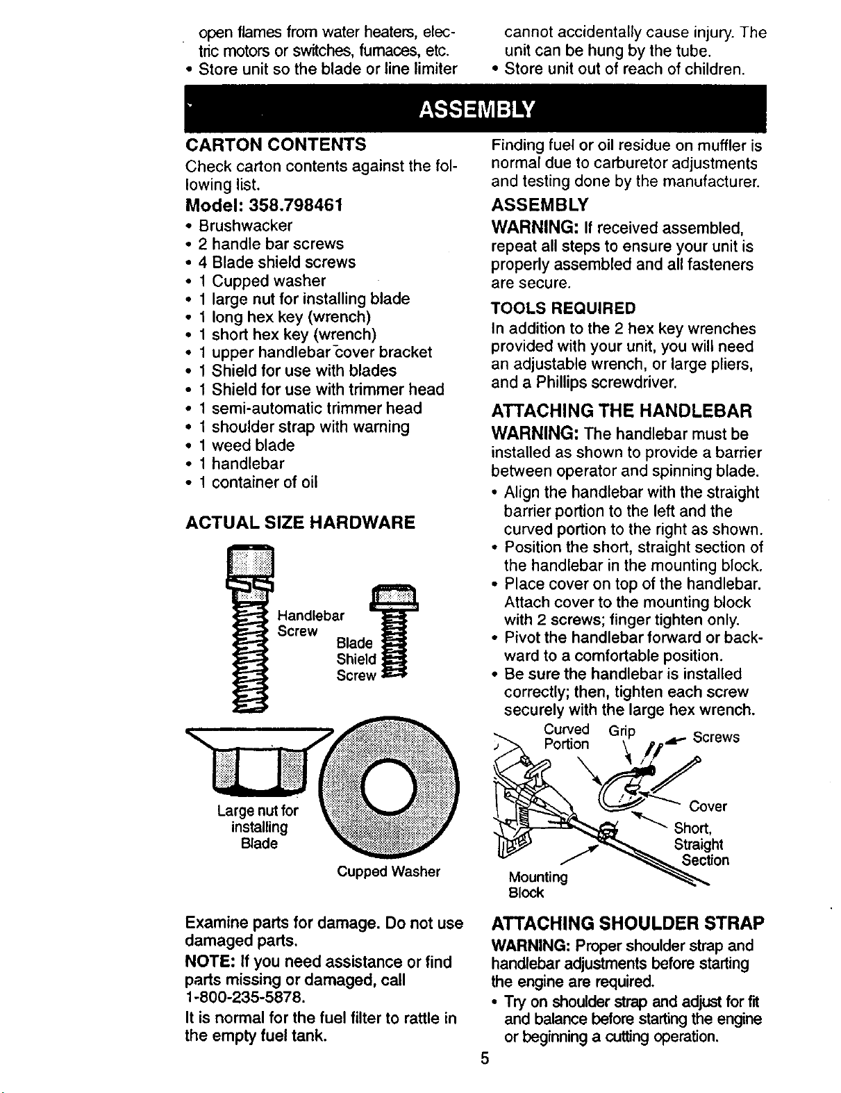
CARTON CONTENTS
Check carton contents against the fol-
lowing list.
Model: 358.798461
• Brushwacker
* 2 handle bar screws
• 4 Blade shield screws
• 1 Cupped washer
• 1 large nut for installing blade
• 1 long hex key (wrench)
• 1 short hex key (wrench)
• 1 upper handlebar_over bracket
• 1 Shield for use with blades
• 1 Shield for use with trimmer head
• 1 semi-automatic trimmer head
• 1 shoulder strap with warning
• 1 weed blade
• 1 handlebar
• 1 container of oil
ACTUAL SIZE HARDWARE
Screw Blade
Handlebar
Shield
Screw
Finding fuel or oil residue on muffler is
normal due to carburetor adjustments
and testing done by the manufacturer.
ASSEMBLY
WARNING: If received assembled,
repeat all steps to ensure your unit is
properly assembled and all fasteners
are secure.
TOOLS REQUIRED
In addition to the 2 hex key wrenches
provided with your unit, you will need
an adjustable wrench, or large pliers,
and a Phillips screwdriver.
ATTACHING THE HANDLEBAR
WARNING: The handlebar must be
installed as shown to provide a barrier
between operator and spinning blade.
• Align the handlebar with the straight
barrier portion to the left and the
curved portion to the right as shown.
• Position the short, straight section of
the handlebar in the mounting block.
• Place cover on top of the handlebar.
Attach cover to the mounting block
with 2 screws; finger tighten only.
• Pivot the handlebar forward or back-
ward to a comfortable position.
• Be sure the handlebar is installed
correctly; then, tighten each screw
securely with the large hex wrench.
Curved Grip Screws
Portion _. //.d_
Large nut for
installing
Blade
Cupped Washer
Examine parts for damage. Do not use
damaged parts.
NOTE: If you need assistance or find
parts missing or damaged, call
1-800-235-5878.
It is normal for the fuel filter to rattle in
the empty fuel tank.
1_ _'_' "_--------"_SCi_:t r
._,'_-'_._ Str "g
Mounting
ATTACHING SHOULDER STRAP
WARNING: Proper shoulder strap and
handlebar adjustments before starting
the engine are required.
• Try on shoulder strap and adjust for fit
and balance before startingthe engine
or beginning a cuttingoperation.
5
F _on
• Insert your nght arm and head through
the shoulder strap and allow it to rest
on your left shoulder. Make sure the
danger sign is on your back and the
hook is to the right side of your waist.
NOTE: A one-half twist is built in the
shoulder strap to allow the strap to rest
flat on the shoulder.
• Adjust the strap, allowing the hook to
be about 6 inches below the waist.
• Fasten the strap hook to the clamp
located between the foam grip and
the mounting block and lift the tool to
the operating position.
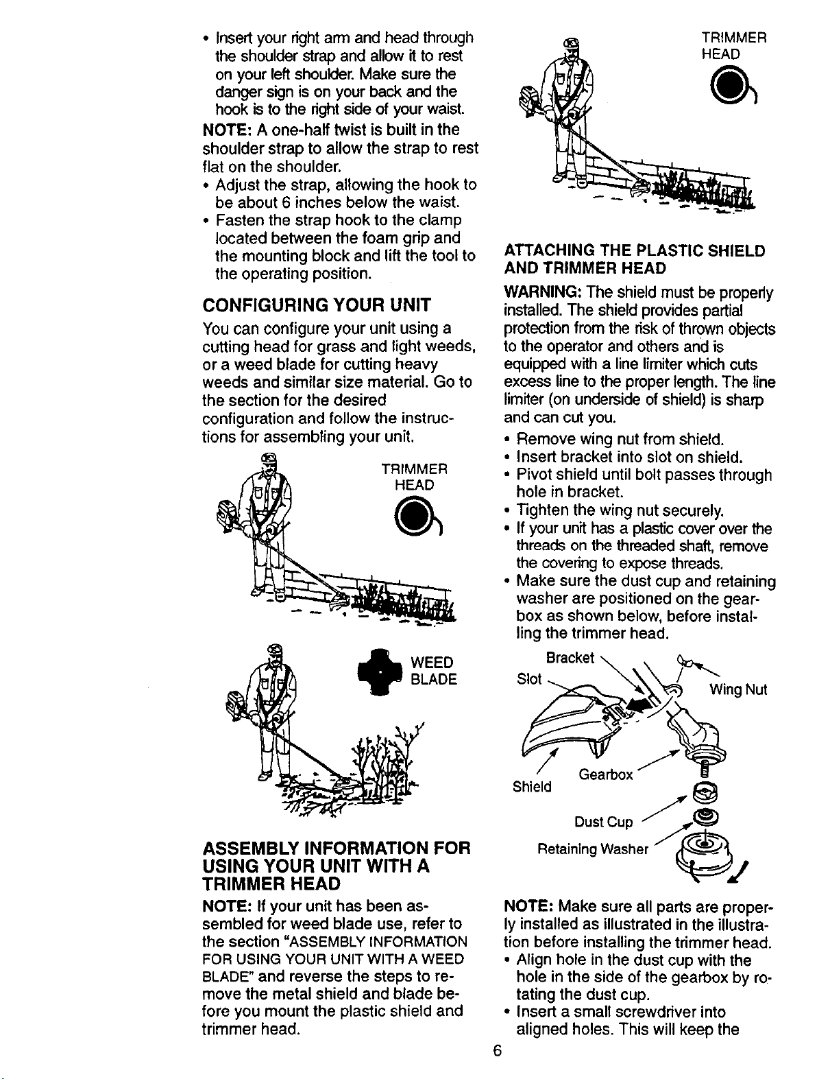
CONFIGURING YOUR UNIT
You can configure your unit using a
cutting head for grass and light weeds,
or a weed blade for cutting heavy
weeds and similar size material. Go to
the section for the desired
configuration and follow the instruc-
tions for assembling your unit.
TRIMMER
HEAD
TRIMMER
HEAD
ATTACHING THE PLASTIC SHIELD
AND TRIMMER HEAD
WARNING: The shield must be properly
installed. The shield provides partial
protection from the risk of thrown objects
to the operator and others and is
equipped with a line limiter which cuts
excess line to the proper length. The line
limiter (on underside of shield) is sharp
and can cut you.
• Remove wing nut from shield.
• Insert bracket into slot on shield.
• Pivot shield until bolt passes through
hole in bracket.
• Tighten the wing nut securely.
• If your unit has a plastic cover over the
threads on the threaded shaft, remove
the coveting to expose threads.
• Make sure the dust cup and retaining
washer are positioned on the gear-
box as shown below, before instal-
ling the trimmer head.
BLADE
WEED
ASSEMBLY INFORMATION FOR
USING YOUR UNIT WITH A
TRIMMER HEAD
NOTE: If your unit has been as-
sembled for weed blade use, refer to
the section "ASSEMBLY INFORMATION
FOR USING YOUR UNIT WITH A WEED
BLADE" and reverse the steps to re-
move the metal shield and blade be-
fore you mount the plastic shield and
trimmer head.
Bracket
Slot
Gearbox
Shield
Wing Nut
DustCup
RetainingWasher _j
NOTE: Make sure all parts are proper-
ly installed as illustrated in the illustra-
tion before installing the trimmer head.
• Align hole in the dust cup with the
hole in the side of the gearbox by ro-
tating the dust cup.
• Insert a small screwdriver into
aligned holes. This will keep the
6
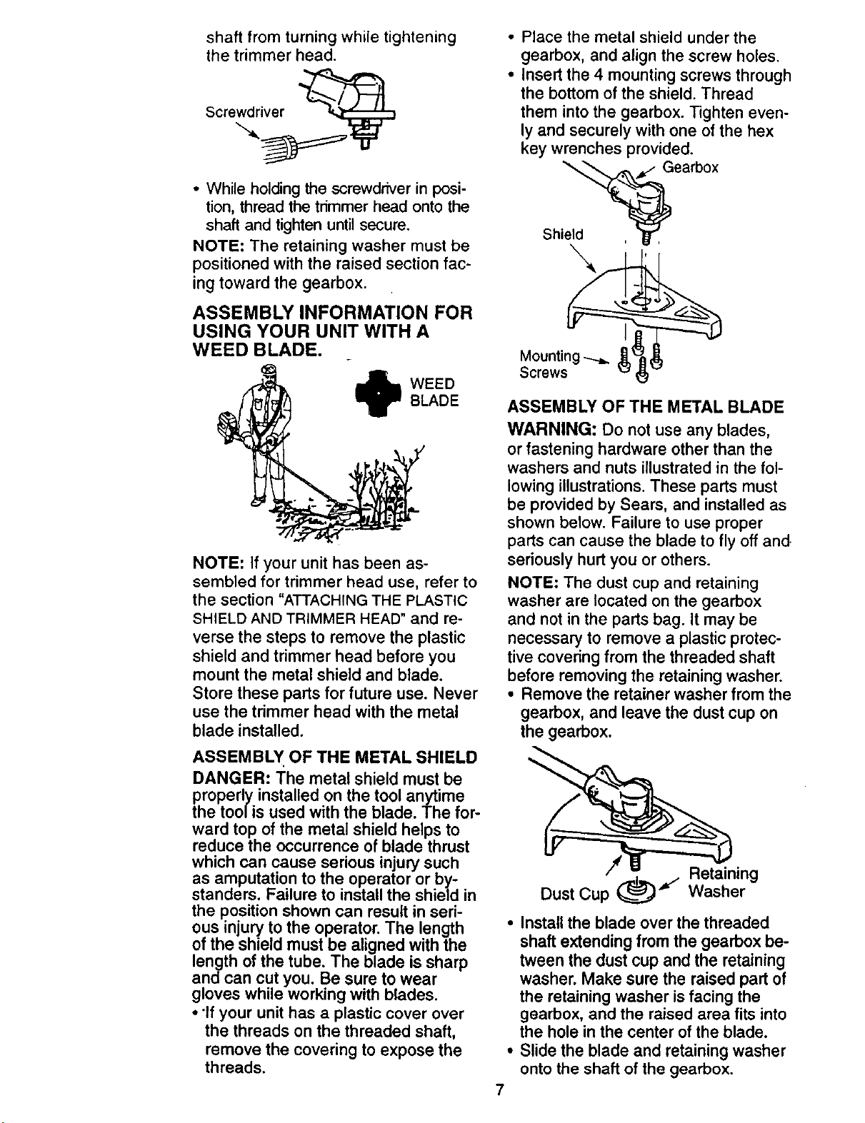
shaft fromturning whiletightening
thetrimmer head.
Screwdriver
• While holding the screwdriver in posi-
tion, thread the trimmer head onto the
shaft and tighten until secure.
NOTE: The retaining washer must be
positioned with the raised section fac-
ing toward the gearbox.
ASSEMBLY INFORMATION FOR
USING YOUR UNIT WITH A
WEED BLADE.
• Place the metal shield under the
gearbox, and align the screw holes.
• Insert the 4 mounting screws through
the bottom of the shield. Thread
them into the gearbox. Tighten even-
ly and securely with one of the hex
key wrenches provided.
Shiel6_, Gearb°x
Mounting
Screws
_IIN WEED
NOTE: If your unit has been as-
sembled for trimmer head use, refer to
the section "ATTACHING THE PLASTIC
SHIELD AND TRIMMER HEAD" and re-
verse the steps to remove the plastic
shield and trimmer head before you
mount the metal shield and blade.
Store these parts for future use. Never
use the trimmer head with the metal
blade installed.
ASSEMBLY OF THE METAL SHIELD
DANGER: The metal shield must be
properly installed on the tool anytime
the tool is used with the blade. The for-
ward top of the metal shield helps to
reduce the occurrence of blade thrust
BLADE
ASSEMBLY OF THE METAL BLADE
WARNING: Do not use any blades,
or fastening hardware other than the
washers and nuts illustrated in the fol-
lowing illustrations. These parts must
be provided by Sears, and installed as
shown below. Failure to use proper
parts can cause the blade to fly off and.
seriously hurt you or others.
NOTE: The dust cup and retaining
washer are located on the gearbox
and not in the parts bag. It may be
necessary to remove a plastic protec-
tive covering from the threaded shaft
before removing the retaining washer.
• Remove the retainer washer from the
gearbox, and leave the dust cup on
the gearbox.
which can cause serious injury such
as amputation to the operator or by
standers, Failure to install the shield in
the position shown can result in seri-
ous injury to the operator. The length
of the shield must be aligned with the
length of the tube. The blade is sharp
and can cut you. Be sure to wear
gloves while working with blades.
• "Ifyour unit has a plastic cover over
the threads on the threaded shaft,
remove the covering to expose the
threads.
Retaining
Dust Cup _(______..,J"_"
• Install the blade over the threaded
shaft extending from the gearbox be-
tween the dust cup and the retaining
washer. Make sure the raised part of
the retaining washer is facing the
gearbox, and the raised area fits into
the hole in the center of the blade.
• Slide the blade and retaining washer
onto the shaft of the gearbox.
7
Washer
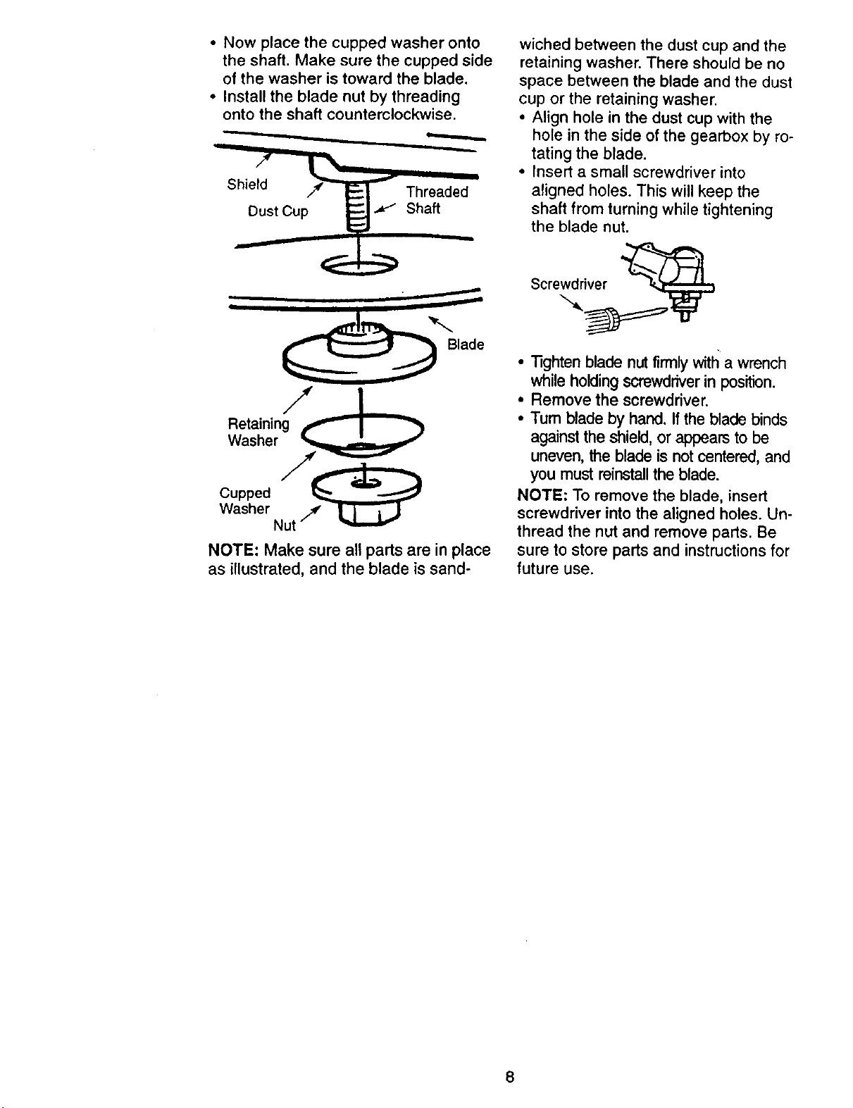
• Now place the cupped washer onto
the shaft. Make sure the cupped side
of the washer is toward the blade.
• Install the blade nut by threading
onto the shaft counterclockwise.
_ Threaded _
._D_DustCup _ Shaft
Reatsa_nerng_l" _ _
co,,ed
Washer Nut j
NOTE: Make sure all parts are in place
as illustrated, and the blade is sand-
wiched between the dust cup and the
retaining washer. There should be no
space between the blade and the dust
cup or the retaining washer.
• Align hole in the dust cup with the
hole in the side of the gearbox by ro-
tating the blade.
• Insert a small screwdriver into
aligned holes. This will keep the
shaft from turning while tightening
the blade nut.
Screwdriver
•"l]ghten blade nut firmly witl_ a wrench
while holding screwdriver in position.
• Remove the screwdriver.
• Tum blade by hand. If the blade binds
against the shield, or appears to be
uneven, the blade is not centered, and
you must reinstall the blade.
NOTE: To remove the blade, insert
screwdriver into the aligned holes. Un-
thread the nut and remove parts. Be
sure to store parts and instructions for
future use.
8
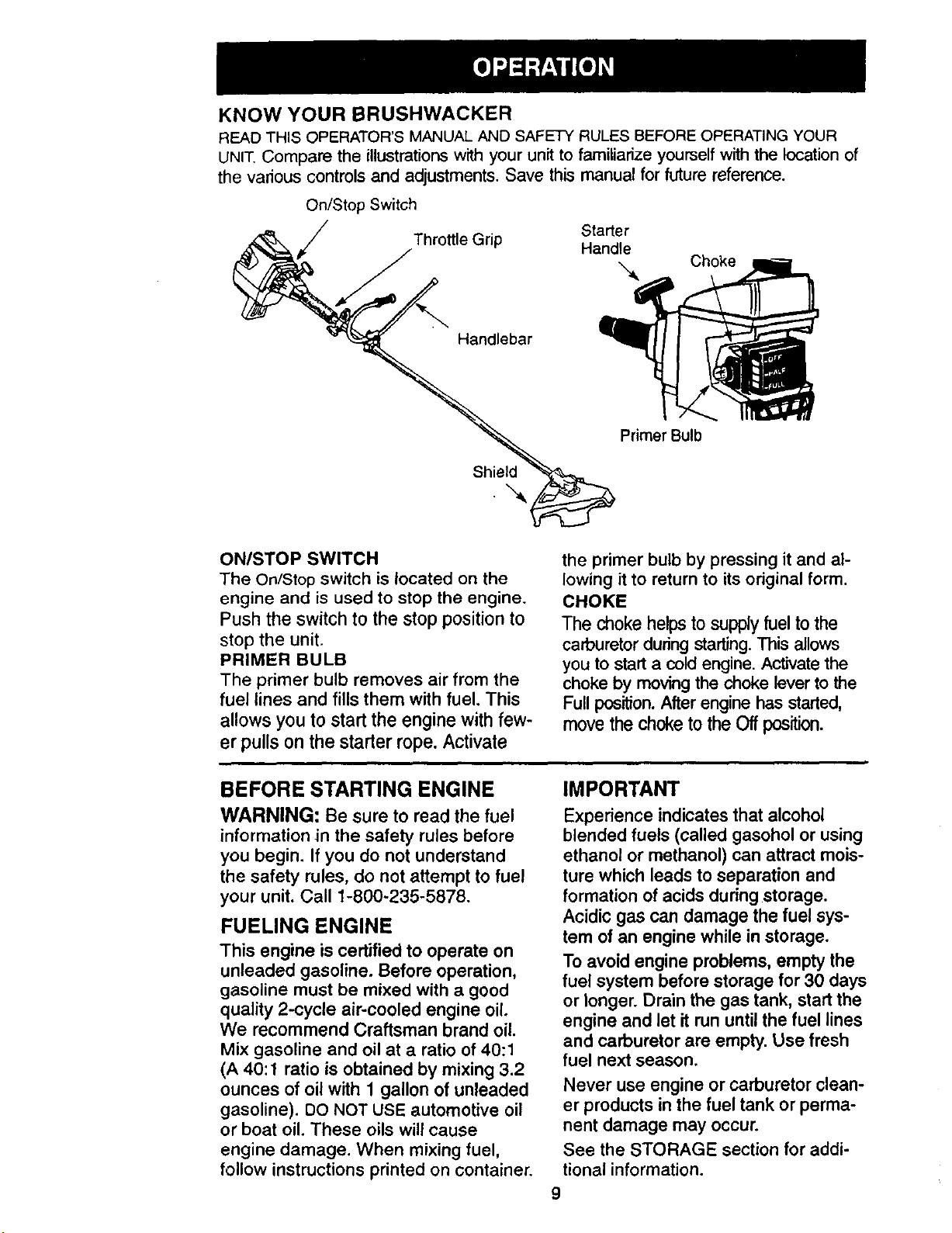
KNOW YOUR BRUSHWACKER
READ THIS OPERATOR'S MANUAL AND SAFETY RULES BEFORE OPERATING YOUR
UNIT.Compare the illustrationswith your unit to familiarize yourself with the locationof
the various controlsand adjustments. Save this manual for future reference.
On/Stop Switch
Starter
#,
Throttle Grip Handle
-_ Choke
Handlebar
Primer Bulb
Shield
ON/STOP SWITCH
The On/Stop switch is located on the
engine and is used to stop the engine.
Push the switch to the stop position to
stop the unit.
PRIMER BULB
The primer bulb removes air from the
fuel lines and fills them with fuel. This
allows you to start the engine with few-
er pulls on the starter rope. Activate
BEFORE STARTING ENGINE
WARNING: Be sure to read the fuel
information in the safety rules before
you begin. If you do not understand
the safety rules, do not attempt to fuel
your unit. Call 1-800-235-5878.
FUELING ENGINE
This engine is certified to operate on
unleaded gasoline. Before operation,
gasoline must be mixed with a good
quality 2-cycle air-cooled engine oil.
We recommend Craftsman brand oil.
Mix gasoline and oil at a ratio of 40:1
(A 40:1 ratio is obtained by mixing 3.2
ounces of oil with 1 gallon of unleaded
gasoline). DO NOT USE automotive oil
or boat oil. These oils will cause
engine damage. When mixing fuel,
follow instructions printed on container.
the primer bulb by pressing it and al-
lowing it to return to its original form.
CHOKE
The choke helps to supply fuel to the
carburetor during starting. This allows
you to start a cold engine. Activate the
choke by moving the choke lever to the
Full pos'_on. After engine has started,
move the choke to the Off position.
IMPORTANT
Experience indicates that alcohol
blended fuels (called gasohol or using
ethanol or methanol) can attract mois-
ture which leads to separation and
formation of acids during storage.
Acidic gas can damage the fuel sys-
tem of an engine while in storage.
To avoid engine problems, empty the
fuel system before storage for 30 days
or longer. Drain the gas tank, start the
engine and let it run until the fuel lines
and carburetor are empty. Use fresh
fuel next season.
Never use engine or carburetor clean-
er products inthe fuel tank or perma-
nent damage may occur.
See the STORAGE section for addi-
tional information.
9
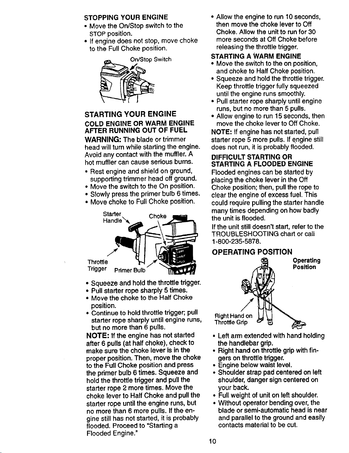
STOPPINGYOURENGINE
• Move the On/Stop switch to the
STOP position.
• If engine does not stop, move choke
to the Full Choke position.
On/Stop Switch
STARTING YOUR ENGINE
COLD ENGINE OR WARM ENGINE
AFTER RUNNING OUT OF FUEL
WARNING: The blade or trimmer
head will turn while starting the engine.
Avoid any contact with the muffler. A
hot muffler can cause serious burns.
• Rest engine and shield on ground,
supporting trimmer head off ground.
• Move the switch to the On position.
• Slowly press the primer bulb 6 times.
• Move choke to Full Choke position.
Starter Choke
Handle_-_
• Allow the engine to run 10 seconds,
then move the choke lever to Off
Choke. Allow the unit to run for 30
more seconds at Off Choke before
releasing the throttle trigger.
STARTING A WARM ENGINE
• Move the switch to the on position,
and choke to Half Choke position.
• Squeeze and hold the throttle trigger.
Keep throttle trigger fully squeezed
until the engine runs smoothly.
• Pull starter rope sharply until engine
runs, but no more than 5 pulls.
• Allow engine to run 15 seconds, then
move the choke lever to Off Choke.
NOTE: If engine has not started, pull
starter rope 5 more pulls. If engine still
does not run, it is probably flooded.
DIFFICULT STARTING OR
STARTING A FLOODED ENGINE
Flooded engines can be started by
placing the choke lever in the Off
Choke position; then, pull the rope to
clear the engine of excess fuel. This
could require pulling the starter handle
many times depending on how badly
the unit is flooded.
If the unit still doesn't start, refer to the
TROUBLESHOOTING chart or call
1-800-235-5878.
Throttle
Trigger Primer Bulb
• Squeeze and hold the throttle trigger.
• Pull starter rope sharply 5 times.
• Move the choke to the Half Choke
position.
• Continue to hold throttle trigger; pull
starter rope sharply until engine runs,
but no more than 6 pulls.
NOTE: If the engine has not started
after 6 pulls (at half choke), check to
make sure the choke lever is in the
proper position. Then, move the choke
to the Full Choke position and press
the primer bulb 6 times. Squeeze and
hold the throttle trigger and pull the
starter rope 2 more times. Move the
choke lever to Half Choke and pull the
starter rope until the engine runs, but
no more than 6 more pulls. If the en-
gine still has not started, it is probably
flooded. Proceed to "Starting a
Flooded Engine."
OPERATING POSITION
Operating
Position
Right Hand on
Throttle Grip
• Left arm extended with hand holding
the handlebar grip.
• Right hand on throttle grip with fin-
gers on throttle trigger.
• Engine below waist level.
• Shoulder strap pad centered on left
shoulder, danger sign centered on
your back.
• Full weight of unit on left shoulder.
• Without operator bending over, the
blade or semi-automatic head is near
and parallel to the ground and easily
contacts material to be cut.
10
OPERATING INSTRUCTIONS
FOR USE WITH TRIMMER HEAD
Bring the engine to cutting speed be-
fore entering the material to be cut.
Do not run engine at a higher speed
than necessary. The cutting line will cut
efficiently when the engine is run at less
than full throttle. At lower speeds, there
is less engine noise and vibration. The
cutting line will last longer and will be
less likely to "weld" onto the spool.
If the trimmer head does not turn when
the engine is in operation, make sure
the drive shaft housing is properly
seated in engine shroud.
Always release the throttle trigger and
allow the engine to return to idle speed
when not cutting.
To stop engine:
• Release the throttle trigger.
• Push and hold down the momentary
switch until the engine has stopped
completely.
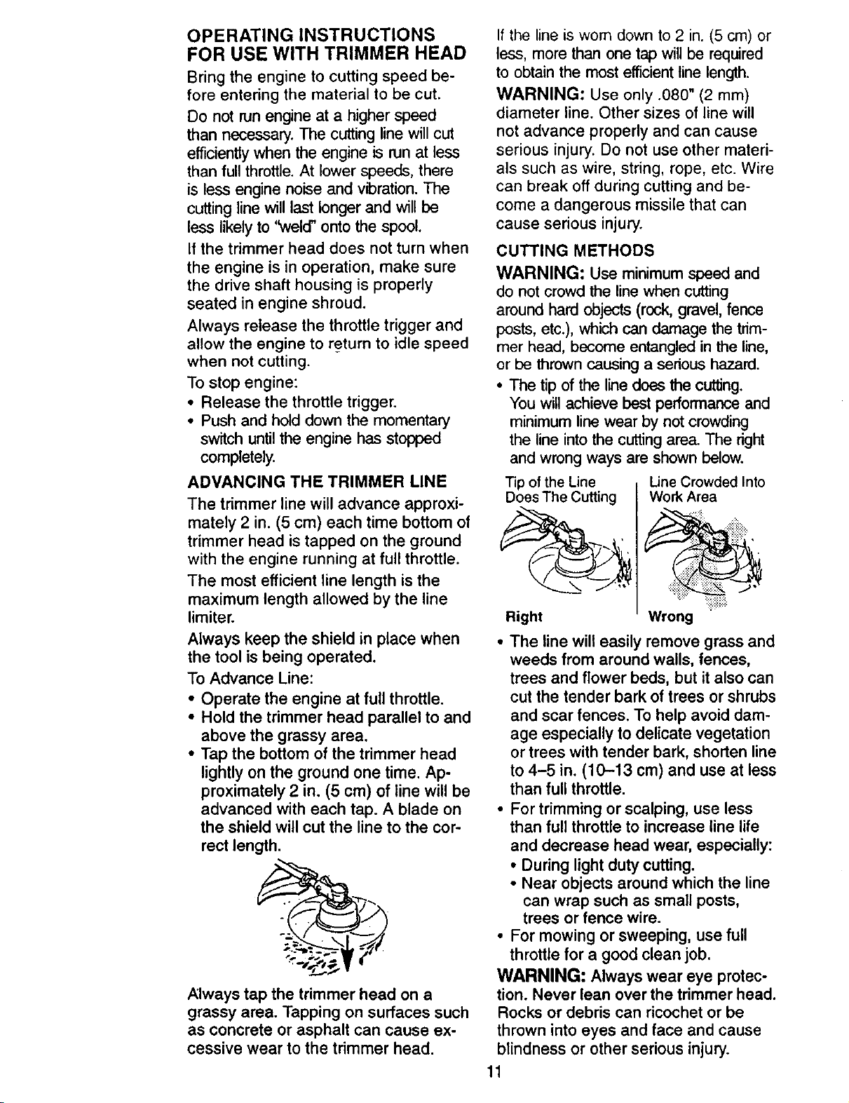
ADVANCING THE TRIMMER LINE
The trimmer line will advance approxi-
mately 2 in. (5 cm) each time bottom of
trimmer head is tapped on the ground
with the engine running at full throttle.
The most efficient line length is the
maximum length allowed by the line
limiter.
Always keep the shield in place when
the tool is being operated.
To Advance Line:
• Operate the engine at full throttle.
• Hold the trimmer head parallel to and
above the grassy area.
• Tap the bottom of the trimmer head
lightly on the ground one time. Ap-
proximately 2 in. (5 cm) of line will be
advanced with each tap. A blade on
the shield will cut the line to the cor-
rect length.
Always tap the trimmer head on a
grassy area. Tapping on surfaces such
as concrete or asphalt can cause ex-
cessive wear to the trimmer head.
If the line is wom down to 2 in. (5 cm) or
less, more than one tap will be required
to obtain the most efficient line length.
WARNING: Use only .080" (2 mm)
diameter line. Other sizes of line will
not advance properly and can cause
serious injury. Do not use other materi-
als such as wire, string, rope, etc. Wire
can break off during cutting and be-
come a dangerous missile that can
cause serious injury.
CUTTING METHODS
WARNING: Use minimum speed and
do not crowd the Finewhen cutting
around hard objects (rock, gravel, fence
posts, etc.), which can damage the trim-
mer head, become entangled in the Fine,
or be thrown causing a serious hazard.
• The tip of the line does the cutting.
You will achieve best performance and
minimum line wear by not crowding
the line into the cutting area. The right
and wrong ways are shown below.
Tipof the Line
Does The Cutting
Right
• The line will easily remove grass and
weeds from around walls, fences,
trees and flower beds, but it also can
cut the tender bark of trees or shrubs
and scar fences. To help avoid dam-
age especially to delicate vegetation
or trees with tender bark, shorten line
to 4-5 in. (10-13 cm) and use at less
than full throttle.
• For trimming or scalping, use less
than full throttle to increase line life
and decrease head wear, especially:
• During light duty cutting.
• Near objects around which the line
can wrap such as small posts,
trees or fence wire.
• For mowing or sweeping, use full
throttle for a good clean job.
WARNING: Always wear eye protec-
tion. Never lean over the trimmer head.
Rocks or debris can ricochet or be
thrown into eyes and face and cause
blindness or other serious injury.
Line Crowded Into
Work Area
:i"!':::::
Wrong
11
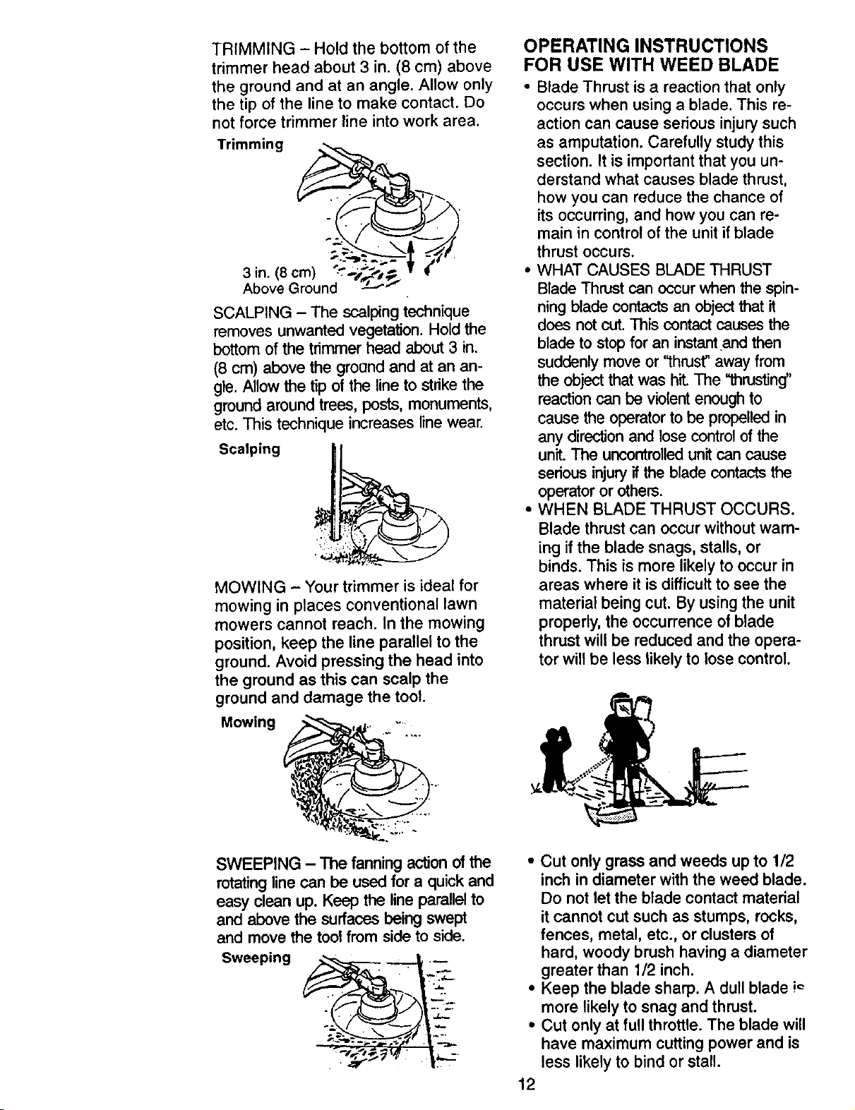
TRIMMING - Hold the bottom of the
trimmer head about 3 in. (8 cm) above
the ground and at an angle. Allow only
the tip of the line to make contact. Do
not force trimmer line into work area.
Trimming
3 ibnov(8(_rmo)un_;__.._;_i' _ t_
SCALPING - The scalping technique
removes unwanted vegetation. Hold the
bottom of the trimmer head about 3 in.
(8 cm) above the ground and at an an-
gle. Allow the tip of the line to strike the
ground around trees, posts, monuments,
etc. This technique increases line wear.
Scalping
MOWING - Your trimmer is ideal for
mowing in places conventional lawn
mowers cannot reach. In the mowing
position, keep the line parallel to the
ground. Avoid pressing the head into
the ground as this can scalp the
ground and damage the tool.
Mowing ,. -....
OPERATING INSTRUCTIONS
FOR USE WITH WEED BLADE
• Blade Thrust is a reaction that only
occurs when using a blade. This re-
action can cause serious injury such
as amputation. Carefully study this
section. It is important that you un-
derstand what causes blade thrust,
how you can reduce the chance of
its occurring, and how you can re-
main in control of the unit if blade
thrust occurs.
• WHAT CAUSES BLADE THRUST
Blade Thrust can occur when the spin-
ning blade contacts an object that it
does not cut. This contact causes the
blade to stop for an instant .and then
suddenly move or "thrust" away from
the object that was hit. The "thrusting"
reaction can be violent enough to
cause the operator to be propelled in
any direction and lose control of the
unit. The uncontrolled unit can cause
serious injury if the blade contacts the
operator or others.
• WHEN BLADE THRUST OCCURS.
Blade thrust can occur without wam-
ing if the blade snags, stalls, or
binds. This is more likely to occur in
areas where it is difficult to see the
material being cut. By using the unit
properly, the occurrence of blade
thrust will be reduced and the opera-
tor will be less likely to lose control.
SWEEPING - The fanning action ofthe
rotating line can be used for a quick and
easy clean up. Keep the line parallelto
and above the surfaces being swept
and move the tool from side to side.
Sweeping
• Cut only grass and weeds up to 1/2
inch in diameter with the weed blade.
Do not let the blade contact material
itcannot cut such as stumps, rocks,
fences, metal, etc., or clusters of
hard, woody brush having a diameter
greater than 1/2 inch.
• Keep the blade sharp. A dull blade i_
more likely to snag and thrust.
• Cut only at full throttle. The blade will
have maximum cutting power and is
less likely to bind or stall.
12

• "Feed" the blade deliberately and not
too rapidly. The blade can thrust
away if it is fed too rapidly.
* Cut only from your right to your left.
Swinging the unit in the same direc-
tion as the blade spins increases the
cutting action.
• Use the shoulder strap and keep a
firm grip on the unit with both hands.
A properly adjusted shoulder strap
will support the weight of the unit,
freeing your arms and hands to con-
trol and guide the cutting motion.
• Keep feet comfortably spread apart
and braced for a possible sudden,
rapid thrust of unit. Do not overreach.
Keep firm footing and balance.
• Keep blade below waist level; it will
be easier to maintain control of unit.
• Do not raise the engine above your
waist as the blade can come danger-
ously close to your body.
• Do not swing the unit with such force
that you are in danger of losing your
balance.
Bring the engine to cutting speed be-
fore entering the material to be cut.
If the blade does not tum when you
squeeze throttle trigger, make sure drive
shaft tube is fully inserted into engine.
Always release the throttle trigger and
allow engine to return to idle speed
when not cutting. The blade should not
turn while the engine is running at idle.
If the blade turns at idle, do not use
your unit. Refer to the Carburetor ad-
justment section or contact your Sears
Service Center.
• Maintain firm footing while using the
unit. Firmly plant feet comfortably
apart.
• Cut while swinging the upper part of
your body from right to left.
• As you move forward to the next
area to cut, be sure to maintain your
balance and footing.
10o'clock
Cut using the 8 o'clock
to 10 o'clock
the blade
WARNING: To avoid serious injury,the
operator or others must not try to clear
away cut material with the engine run-
ning or the blade tuming. Stop engine
and blade before removing materials
wrapped around the blade or tube.
MAINTENANCE SCHEDULE
CARE & MAINTENANCE TASK
Check for Loose fasteners and parts
Check for damaged or worn parts
Clean unit and labels
Clean air filter
Inspect and clean spark arrestor
Replace spark plug
GENERALRECOMMENDATIONS
The warranty on this unit does not cov-
er items that have been subjected to
operator abuse or negligence. To re-
ceive full value from the warranty, the
operator must maintain unit as instruct-
ed in this manual. Various adjustments
will need to be made periodically to
propedy maintain your unit.
WHEN TO PERFORM
Before each use
Before each use
After each use
Every 5 hours of operation
Every 25 hours of operation
Yearly
CHECK FOR LOOSE
FASTENERS AND PARTS
• Spark Plug Boot
• Air Filter
• Housing Screws
• Assist Handle Screws
• Shield
13
 Loading...