

Craftsman 358798270 Owner’s Manual
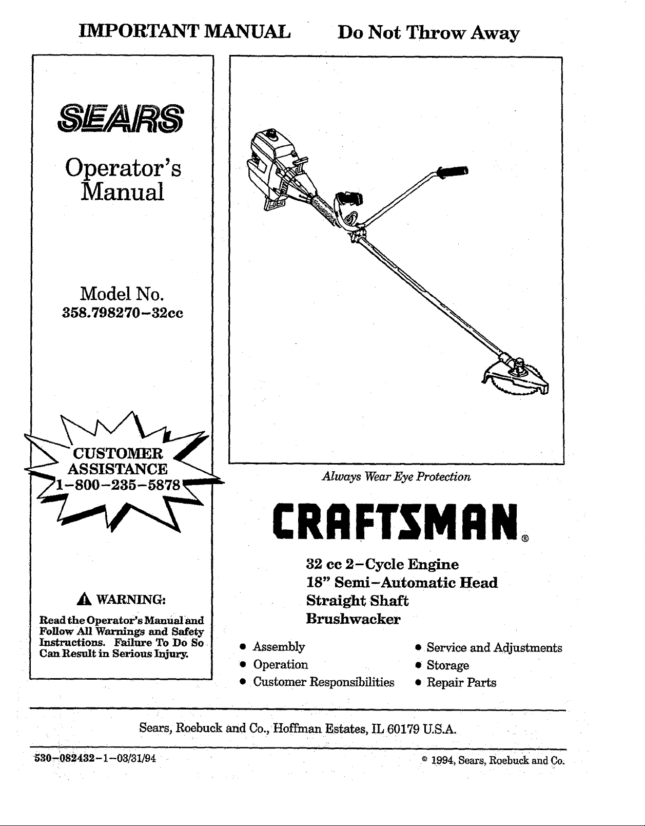
IMPORTANT MANUAL Do Not Throw Away
Operator's
Manual
Model No.
358.798270-32ce
CUSTOMER
ASSISTANCE
_k WARNING:
Read the Operator's Manual and
Follow All Warnings and Safety
Instructions. Failure To Do So
Can Result in Serious Injury.
Sears, Roebuck and Co., Hoffman Estates, IL 60179 U.S_.
Always Wear Eye Protection
CRRFTSMRNo
32 ce 2-Cycle Engine
18" Semi-Automatic Head
Straight Shaft
Brushwacker
• Assembly
• Operation
• Customer Responsibilities
• Service and Adjustments
• Storage
• Repair Parts
530.082432-1-03/31/94 © 1994, Sears, Roebuck and Co.
TABLF, OF CONTENTS
WARNINGS AND SAFETY INSTRUCTIONS 3
KNOW YOUR UNIT ........................ 5
ASSEMBLY ................................ 6
FUELING YOUR ENGINE . 9
STARTING YOUR ENGINE ................ 10
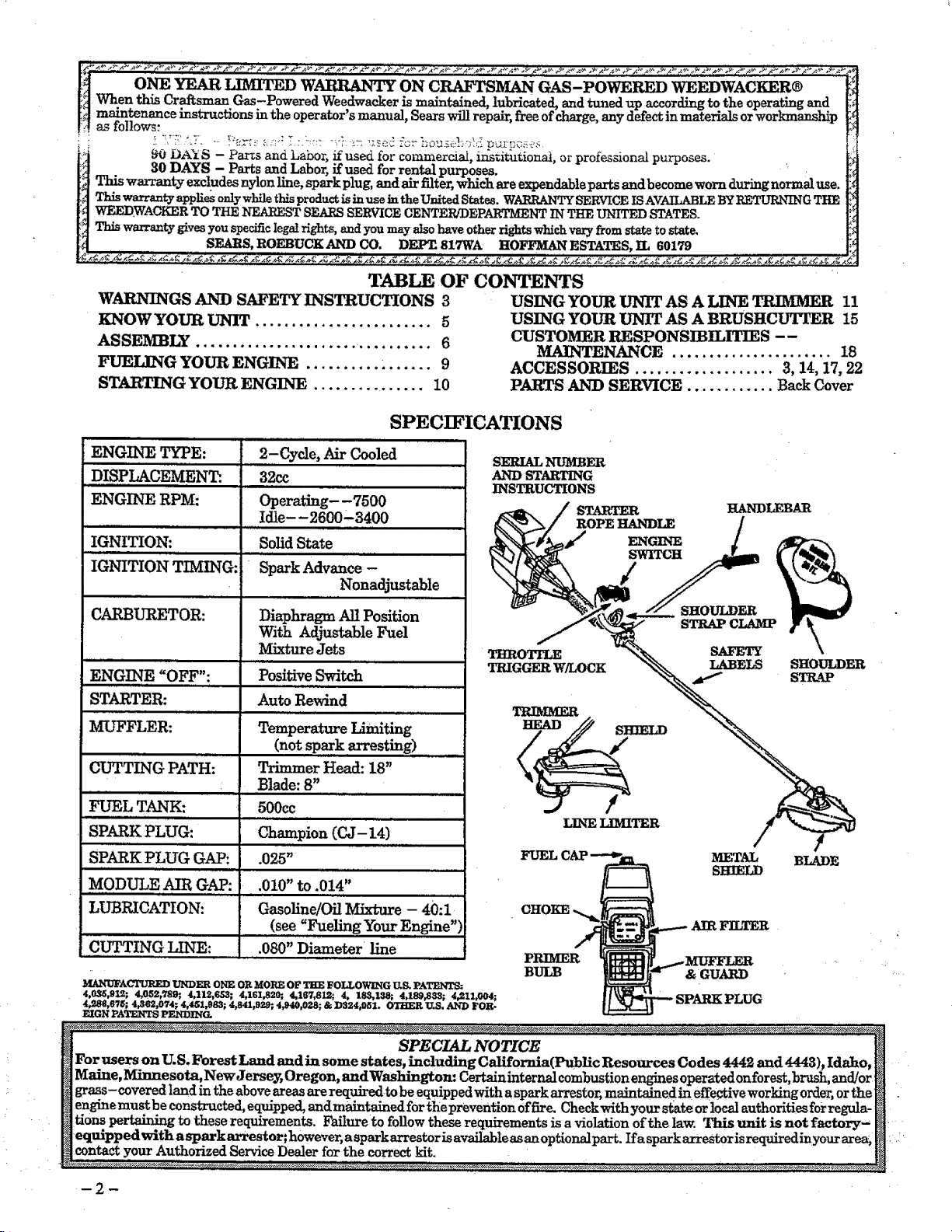
SPECIFICATIONS
USING YOUR UNIT AS A LINE TRIMMER 11
USING YOUR UNIT AS A BRUSHCUTTER 15
CUSTOMER RESPONSIBILITIES --
MAINTENANCE ...................... 18
ACCESSORIES ................... 3, 14, 17, 22
PARTS AND SERVICE ............ Back Cover
ENGINE TYPE: 2-Cycle, Air Cooled
DISPLACEMENT: 32cc
SERIAL NIFMBER
AND STARTING
INSTRUCTIONS
ENGINE RPM: Operating-,7500
Idle- -2600-3400
IGNITION: Solid State
IGNITION TIMING: Spark Advance -
m,, .,,,,, . ,,. ,, ............
Nonadjustable
CARBtYRETOR: Diaphragm All Position
With Adjustable Fuel
,N .... • ,,R ,,,,,,,,,,u, i i
ENGINE "OFF": Positive Switch
.ll , i .................................
Mixture Jets
STARTER: Auto Rewind
THRO_
TRIGGERW/LOCK
TRIMMER
MUFFLER: Temperature Limiting
(not spark arresting)
CUTTING PATH: Trimmer Head: 18"
HHI.ll I ,I I,.,I ll,ll
Blade: 8"
FUEL TANK: 500ee
SPARK PLUG: Champion (CJ- 14)
SPARK PLUG GAP: .025" '....................
, ,,, ,,,,,,
FUEL(
MODULE AIR GAP: .010"to.014"
LUBRICATION: Gasoline/OilMixture- 40:1
CUTTING LINE: .060"Diameter line
Y_t.N_FACTUR]RD U'NDER ONE OR MORE OF THE FOLLOWING U.S. PATENTS:
4,0_,9L_; 4,052,789; 4,112,653; 4,161,820;, 4,16_',812_ 4, 185,138; 4,189,833; 4_I1,004;
4_8B,67_; 4,362,074; 4,451,983; 4,841,929; 4,940r028; & D324,051. OTHER U.S. AND FOR-
EIGN PATENTS PENDING.
PRIMER
BULB & GUAP,D
STARTER
ROPE HANDLE
ENGINE
SWITCH
/
LINE LIMITER
HANDLEBAR
SHOULDER
STRAP CLAMP
SAFETY
LABELS SHOULDER
METAL BLADE
SHIELD
FILTER
STRAP
/
SPECIAL NOTICE
For users on U.S. Forest Land and in some states, including California(Public Resources Codes 4442 and 4443), Idaho,
Maine, Minnesota, New Jerse_ Oregon, andWashington: Certain internal combustion engines operated on forest, brush, and/or
grass-covered land in the above areas are requiredto be equipped with a spark arrestor, maintaine d ineffective working order, or the
engine must be constructed, equipped, and maintained for the prevention of fire. Check with your state or local authorities for regula-
tions pertaining to these requirements. Failure to follow these requL_ements is a violation ofthe law. This unit is not factory-
equipped with asparkarrestor; however, a spark arrestoris available as an optionalpart. Ira sparkarrestoris requiredinyour area_
content your Authorized Service Dealer for the correct kit.
WARNINGS AND SAFETY INSTRUCTIONS
(See Additional Safety Instructions throughout this Manual)
,_, DANGER -- THIS POWER TOOL CAN BE DANGEROUS! This unit can cause serious
injury including amputation or blindness to the operator and others. The warnings and safe_- ins_r_tc-
tions in this manual must be followed to provide reasonable safety and efficiency in using the unit. The
operator is responsible for following the warnings and instructions in this manual and on the unit. Read
the entire Operator's Manual before assembling and using the unit! Restrict the use of this unit to persons who read,
understand, and follow the warnings and instructions in this manual and on the unit.
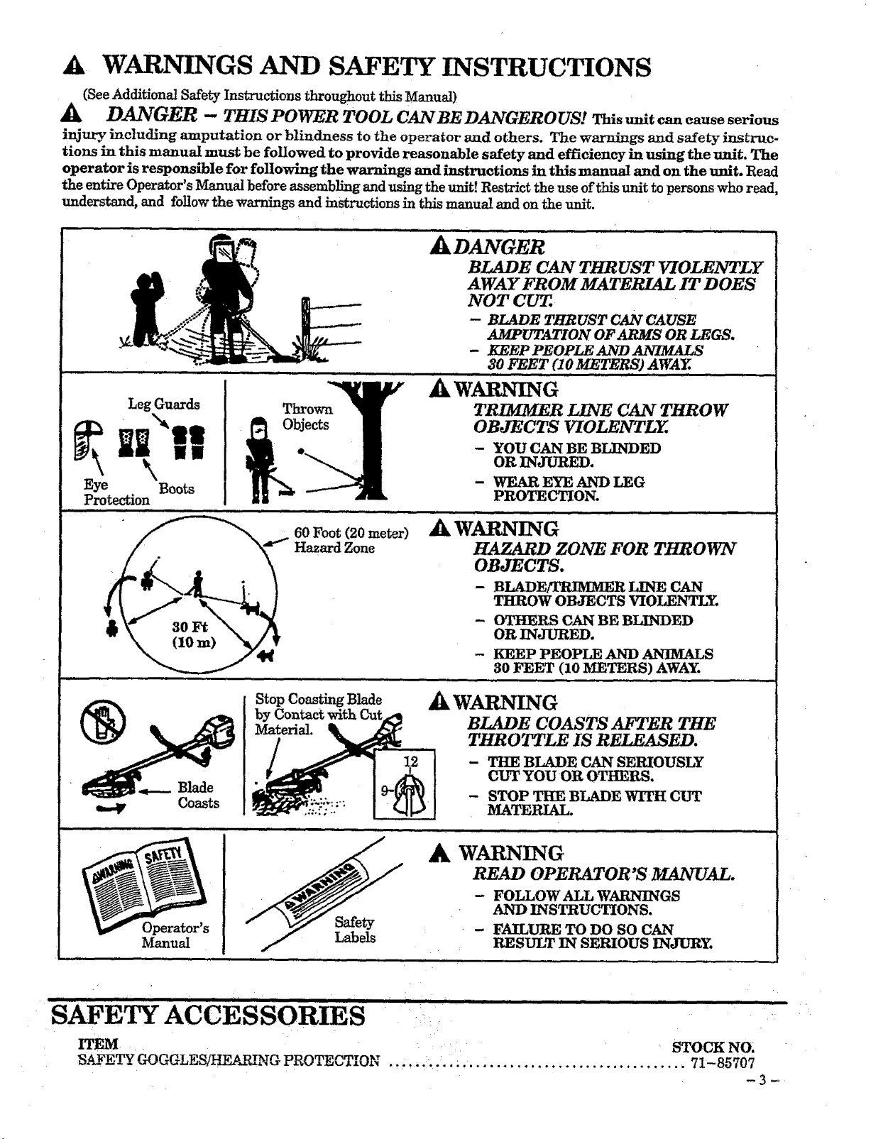
ADANGER .......
BLADE CAN THRUST VIOLENTLY
AWAY FROM MATERIAL IT DOES
NOT CUT..
-- BLADE THRUST CAN CAUSE
AMPUTATION OF ARMS OR LEGS.
- KEEP PEOPLE AND ANIMALS
30 FEET (10 METERS) AWAY.
W_NING
Leg Guards
Thrown
bjects
TRIMMER LINE CAN THROW
OBJECTS VIOLF,NTLY.
- YOU CAN BE BI3NDED
OR INJ't_.ED.
- WEAR EYE AND LEG
PROTECTION.
.....,,,H ,,,,,,,, i i ,,,N
Operator's
Manual
60 Foot (20 meter-)
Hazard Zone
Stop Coasting Blade
by Contact with
Material.
Safety
Labels
HAZARD ZONE FOR THROWN
OBJECTS.
- BLADE/TRIMMER LINE CAN
THROW OBJECTS VIOLENTLY.
- OTHERS CAN BE BLINDED
OR INJURED.
- KEEP PEOPI.E AND ANIMALS
30 FEET (10 METERS) AWAY.
_k WAP,NING
BLADE COASTS AFTER THE
THROTTLE IS RELEASED.
- THE BLADE CAN SERIOUSLY
CUT YOUOR OTHERS.
- STOP THE BLADE WITH CUT
MATERIAL.
A WARNING
READ OPERATOR'S MANUAL.
- FOLLOW ALL WARNINGS
AND INSTRUCTIONS.
- F'_URE TO DO SO CAN
RESULT IN SERIOUS INJURY.
SAFETY ACCESSORIES
ITE_
S._____,_ C_)GGLESL_NG PROTECTION
STOCK NO.
•. :..... • ._.•.. ................................ 71-85707
_3_
ARNINGS AND SAFETY INSTRUCTIONS....(Continued)
A OPERATOR SAFETY
o A]w_v_ _,_r s_e_ eve Drotect_0_.
boots, and gloves. Wearing safety leg guards is rec-
ommended. Do not go barefoot or wear sandals,
jewelry, short pants, short sleeves, loose clothing,
or clothing with loosely hangingties, straps, tas-
sels, etc.; they can be caught in moving parts. Be-
_fgtfully covered w;ffihelp protect you from pieces
oxic plants such as poison ivy thrown by blade
or trimmer head which could be more of a hazard
than touching the plant itself.
• Secure hair so it is above shoulder length.
• Do not operate unit when you are tired, ill, or un-
der the influence of alcohol, drugs, or medication.
• Wear hearing protection if you use the unit for
more than I- 1/2 hours per day.
• Never start or run the engine inside a dosedroom
or building. Breathing exhaust fumes can kill.
• Keep handles free of off and fuel.
• Always use the handlebar and a properly adjusted
shoulder strap with a blade. See '_kssembly."
A UNIT/MAIntENANCE SAFETY
• Look for and replace damaged or loose parts be-
fore each u_. Look for and repair fuelleaks before
use. Keep the unit in good working condition.
• Throw away blades that are bent, warped,
cracked, broken, or damaged in any other way.
Replace trimmer head parts that are cracked,
Ch_pped,broken, or damaged in any other waybe-
fore using the unit.
• Maintain the unit accordingto recommended pro-
eedures. Keep the blade sharp. Keep the cutting
line at the proper length.
• Use only .080" diameter SEAB._SLaser Line®
brand line. Never use wire, rope, string, etc.
• Install the required shield properly before using
the unit. Use the metal shield for all weed blade
use. Use the plastic shield for all line trimmer use.
• Use only specified blade or trimmer head; make
sure it is properly installed and securely fastened.
• Never start engine with dutch shroud removed.
The clutch can fly off and cause serious injury.
• Be sure blade or trimmer head stopsturningwhen
engine idles.
• Disconnect the spark plug before performing
maintenance (except carburetor adjustments).
• Make carburetor adjustments with the lower end
supported to prevent the blade or trimmer line
from contacting any object. Hold the unit by hand;
do not use the shoulder strap for support.
• Keep others away when making carburetor ad-
justments.
• Use only genuine SEARS accessories as recom-
mended for this unit.
If situations occur which are not covered in this manual, use care and good judgment.
If you need assistance, contact your Authorized Service Dealer or the
CUSTOMER ASSISTANCE HOTLINE at 1-800-235-5878.
_k FUEL SAFETY
• Mix and pour fuel outdoors.
• Keep away from sparks or flames.
• Use a container approved for fuel.
• Do not smoke or allow smoking near fuel or the
unit or while using the unit.
• Wipe up all fuel spills before starting engine.
• Move at least 10 feet (3 meters) away from fueling
site before star_g engine.
Stop engine and allow it to cool before removing
fuel cap.
• Empty the fuel tank before storing the unit. Use
up fuel lef_ in the carburetor by starting the en-
gine and letting it run until it stops.
• Store unit and fi_eI in an area where fuel vapors
cannot reach sparks or open flames from water
heaters, electric motors or switches, furnaces, etc.
A CUTTING SAFETY
• Inspect the areato be cut before eachuse. Remove
objects (rocks, broken glass, nails, wire, string,
etc.) which can be thrown or become entangled in
the blade or trimmer head.
• Keep others including children, animals, bystand-
ers, and helpers outside the 60 foot (20 meter)
Hazard Zone. Stop the engine immediately if you
are approached.
• Always keep engine on the right-hand side of
yourbody.
• Hold the unit firmly with both hands.
• Keep firm footing and balance. Do not over-
reach.
• Keep blade or trimmer head below waist level.
• Do not raise the engine above your waist.
• Keep allparts ofyour body away from blade, trim-
mer head, and muffler when engine is runrming.
• Cut from your right to your left.
• Use only for jobs explained in this manual.
A TRANSPORTINGAND STORAGE
: Stop the unit before carrying.
Keep the muffler away from yourbody.
Allow engine to cool and secure unit before stor-
ing or transporting it in a -vehicle.
Empty the fuel tank before storing or transport-
ing the unit. Use up fuel left in the carburetor by
starting the engine andlettingit run until it stops.
• Store unit and fuel in an area where fuel vapors
cannot reach sparks or open flames from water
heaters, electric motors or switches, fbxnaces, etc.
• Store unit so the blade or line limiter cannot acci-
dentally cause injury. The unit can be hung by the
bracket below engine or by drive shaft housing.
• Store the unit out of reactfof children.
-4-
IIIIIIIIIII IIIIIII I III IIIIIIIIIIIIIIIIIIIIIIII II IIIII II,,,,IH ,I I I ,,,,,,,,,II II I,II I I ,,,,, ,ll I I ,,,,,,,,,,,,
KNOW "fOUR UNIT
i J ,,,,,, , ,,,,,,,, .......................................
A.
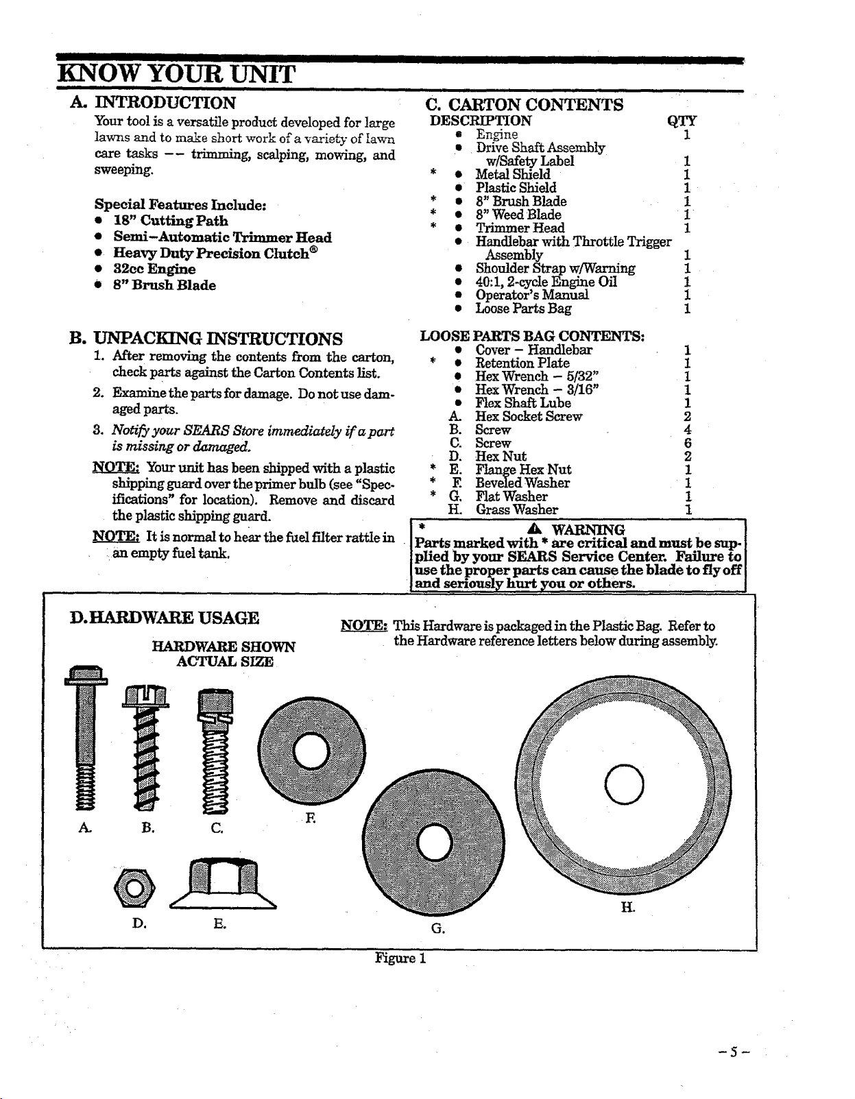
INTRODUCTION
Your too! is a versatile product developed for large
lawns and to make short work of a variety of lawn
care tasks -- trimming, scalping, mowing, and
sweeping.
Special Features Include:
t 18" Cutting Path
o
Semi-Automatic Trimmer Head
o
Heavy Duty Precision Clutch _
32cc Engine
o
8" Brush Blade
c.CARTONCONTENTS
DESCRIPTION
" En_ne
• _DriveShaftAssemb!y
• • Meta! Shield
• • 8" Brush Blade
• • 8" Weed Blade
• • Trimmer Head
w/SafetyLabel
• Plastic Shield
Handlebar with Throttle Trigger
Assembly
0
Shoulder Strap w/Warning
40:1, 2-cycle Engine Off
Operator's Manual
Loose Parts Bag
QTY
1
I
i
I
i
1
I
i
I
i
1
I
B. DNPACKING INSTRUCTIONS
1. After removing the contents from the carton,
check parts against the Carton Contents list.
2. Examine the parts for damage. Do not use dam-
agedparts.
3. Notil_ yaur SEARS Store immediately if a part
is missing or damaged.
Your unit has been shipped with a plastic
shipping guard over the primer bulb (see "Spec-
ifications" for location). Remove and discard
the plastic shipping guard. [ * A WARNING [
It is normal to hear the _el filter rattle in [Parts marked with * are critical and must be sup.
• :an empty fuel tank, {plied by your SEARS Service Center. Failure to{
D.HARDWAREUSAGE
HARDWARE SHOWN
ACTUAL SIZE
NOT ThisHardware is packaged in the Plastic Bag. Refer to
LOOSE PARTS BAG CONTENTS:
• Cover- Handlebar
* • Retention Plate
• Hex Wrench - 5/32"
• Hex Wrench - 3/16 _
• Flex Shat_ Lube
Hex Socket Screw
B. Screw
C. Screw
D. Hex Nut
* E. Flange HexNut
* E Beveled Washer
* G. FlatWasher
H. Grass Washer 1
]use the proper parts can cause the blade to fly off
, ,i,_!_d sen_l_hurty0u or0thers, ...... .....................:, [
the Hardware reference letters below during assembly.
1
t
1
1
1
2
4
6
2
1
1
1
A. B. C.
©
R
H.
E.
Figure 1
G,
-5-
ASSEMBLY
(if tool is received assembled, repeat all steps in this section to be sure assembly is correct and is ad-
justed for the operator.)
This Operator's Manual is designed to help you as-
semble the tool and to provide its safe operation. It is
important that you read the entire manual to become
familiar with the tool before you begin assembly. If
you have any questions or need further assistance,
call our CUSTOMER ASSISTANCE HOTLINE at
1-800-235-5878.
i i ,,,m,,,,, ii i ii iii i,,,,,,,,, ,,,i i
B.ASSEMBLY STEPS
Hardware referred to in the following sections
are shown in actual size in Figure I.
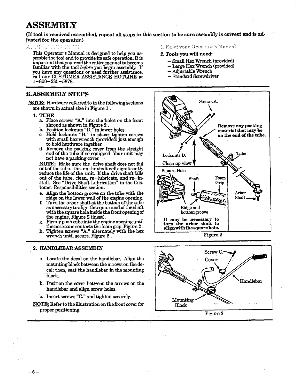
1. TUBE
a. Place screws "A." into the holes on the front
shroudas shown in Figure2.
b. Positionlocknuts"D."inlowerholes.
c. Hold locknuts "D." in place; tighten screws
with small hex wrench (provided) just enough
to hold hardware together.
d. Remove the packing cover from the straight
end of the tube if so equipped. Your unit may
not have a packing cover.
_TE: Make sure the drive shaft does not fall
out of the tube. Dirt on the shaft will significantly
reduce the life of the unit. If the drive shaft falls
out of the tube, dean, re-lubricate, and re-in-
stal!. See "Drive Shaft Lubrication" in the Cus-
tomer Responsibilities section.
e. Align the bottom groove on the tube with the
ridge on the lower wall of the engine opening.
f. Turn the arbor shaft at the bottom of the tube
as necessary to _ the square endofthe shaft
with the square h01e inside the front opening of
the engine. Figure 2 (inset).
g. Firmlypush _abeinto the engine openinguntil
the nose cone contacts the foam grip. Figure 2.
h. Tighten screws "A_" alternately ,_ith the hex
wrench until secure. Figure 2.
ii i ii MII u IV I ,,,,,,, ,,,,JUl, II
2. HANDLEBAR ASSEMBLY
2. Tools you will need:
- Small Hex Wrench (provided)
- Large Hex Wrench (provided)
- Adjustable Wrench
- Standard Screwdriver
iiiiiiiiiiiiii i ii ii iiii i H
ScrewsA.
\
/
Locknuts D.
Close up view
;Hole
It may be necessary to
turn the arbor shaft to
align with the square hole.
Figure 2
|, i , i
material that may be
onthe end of the tube.
a. Locate the decal on the handlebar. Align the
mounting block between the arrows on the de-
cal; then, seat the handlebar in the mounting
block.
b.Positionthe coverbetweenthe arrowson the
handlebarand alignscrewholes.
c. Insertscrews"C."and tightensecurely.
NOTE: Refer to the illustration on the front cover for
proper positioning.
,,,11111 i iiii ii iii i i !
Cover /
Handlebar
Block
Figure 3
3_
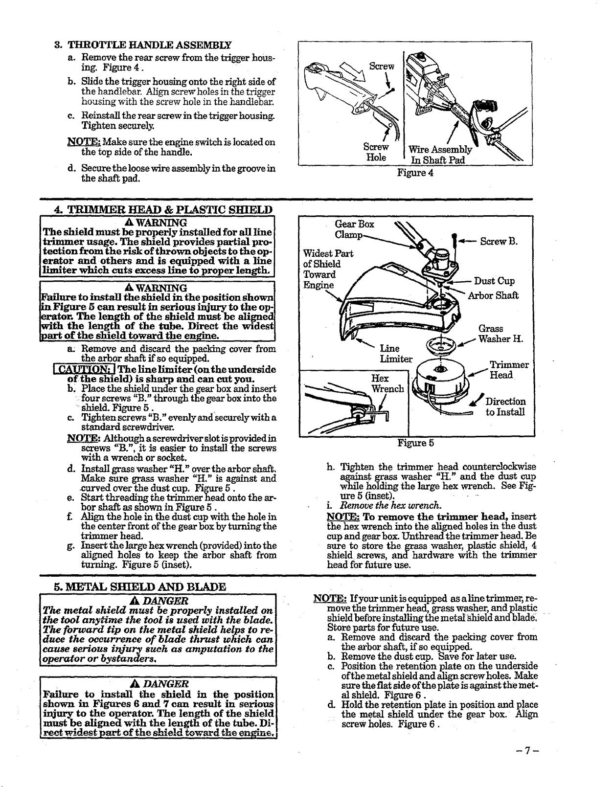
THROTTLE HANDLE ASSEMBLY
a. Remove the rear screw from the trigger hous-
ing. Figure 4.
b. Slide the trigger housing onto the right side of
the handlebar. Align screw holes in the trigger
housing with the screw hole in the handlebar.
c. Reinstall the rear screwin the trigger housing.
Tighten securely.
Make sure the engine switch is located on
the top side of the handle.
d. Secure the loosewire assemblyin the groove in
the shaft pad.
.............. i IIHI II I IIIIIIIIIIIIIIIII
4. TRIMMER HEAD & PLASTIC SHIELD
[ _ A WARNING
,_tv_e to install the shield in the position shown
_in Figure 5 can result in serious injury to the op-
[era tor, The length of the shield must be ali_rned
[with the length of the tube. Direct the widest
]part of the shield toward the engine,
a: Remove and discard the packing cover from
the arbor shaft ffso equipped,
The, line limiter (on the underside
ld) m sharp and can cut you.
b3 Place the shield under the gear box and insert
four screws "B." through the gear box into the
=shield. Figure 5.
c, Tighten screws "B." evenlyandsecurelywith a
standard screwdriver.
O__0___-:_,Althou h ascrowdrivers!otmpromdedm
go . •
screws "B.', It Is easier to mstall the screws
with a wrench or socket.
d. Install grass washer "H." over the arbor shaft.
Make sure grass washer "H," is against and
___ved over the dust cup, Figure 5.
e. b2art threading the trimmer head onto the ar-
bor shai_ as shown in Figure 5.
f. Align the hole in the dust cup with the hole in
the center front of the gear box by turning the
trimmer head.
g. Insert the large hex wrench (provided) into the
aligned holes to keep the arbor shaft from
turning. Figure 5 (inset).
5, METAL SHIELD AND BLADE
A DANOER
The metal shield must be properly installed on
the tool any_m, e the tool _s used with the blade.
The forward tip on the metal shield helps to re.
duce the occurrence of blade thrust which can
cause serious injury such as amputation to the
operator or bystanders.
ApAN E ....!
Failure to _astall the shield in the position I
shown in Figures 6 and 7 can result in serious [
injury to the operator. The length of the shield[
must be aligned with thelength of the tube. Di- [
reef widest pa.-_of the shleldtow ,ardthe engine.[
Screw Wire Assembly
Hole In Shaft Pad
Figure 4
Gear Box
Widest Part
of Shield
Toward
Dust Cup
Arbor Shaft
Line
Trimmer
_Direction
to Install
Figure 5
h. Tighten the trimmer head counterclockwise
against grass washer "H." and the dust cup
while holding the large hex wrench. See Fig-
ure 5 (inset). - . --
i. Remove the hex wrench.
NOTE: To remove the trimmer head, insert
the hex wrench into the aligned holes in the dust
cup and gear box. Unthread the trimmer head. Be
sure to store the grass washer, plastic shield, 4
shield screws, and hardware with the trimmer
head for future use.
iii ii ,,,,,,,,m i i ,,li!,mu,llli i IHIIlll
NOTE: Ifyour unit is equipped as aline trimmer, re-
move the trimmer head, grass washer, and plastic
shield before instalh'ngthe metalshield and blade: ....
Store parts for future use.
a. Remove and discard the packing cover from
the arbor shaft, ff so equipped.
b. Remove the dust cup. Save for later use.
e. Position the retention plate on the underside
of the metal shield and align screw holes. Make
sure the flat side ofthe plate is against the met-
alshield.Figure6.
d. Hold theretentionplateinpositionand place
the metal shieldunder the gear box. Align
screwholes.Figure6.
-7-
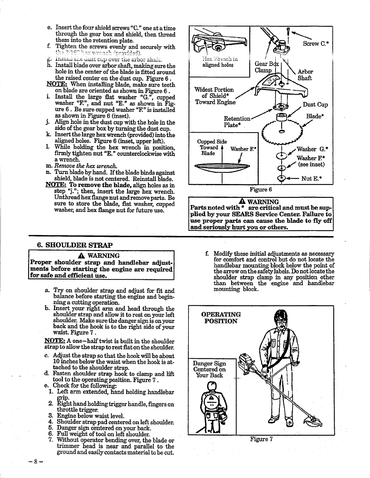
e. Insert the four shield screws "C." one at a time
through the gear box and shield, then thread
them into the retention plate.
f. Tighten the screws evenly and securely with
g. iI_.DL_ _i=_d_s_ o_p over _i_ ea'bor sh_.
h. Install blade over arbor shaft, making sure the
hole in the center of the blade is fitted around
the raised center on the dust cup. Figure 6.
When installing blade, make sure teeth
on blade are oriented as shown in Fig-are 6.
i. Install the large flat washer "Go', cupped
washer "E", and nut "E." as shown in Fig-
ure 6. Be sure cupped washer "E" is installed
as shown in Figure 6 (inset).
j. Align hole in the dust cup with the hole in the
side of the gear box by _ting the dust cup.
k. Insert the large hex wrench (provided) into the
aligned holes. Figure 6 (inset, upper left).
1. While holding the hex wrench in position,
firmly tighten nut "E." countp_rclockwise with
a wrench.
rn_Remove thehexwrench.
n. Turn blade by hand. If the blade binds against
shield, blade is not centered. Reinstall blade.
NOTE: To remove the blade, align holes as in
step "j.'; then, insert the large hex wrench.
Unthread hex flange nut andremoveparts. Be
sure to store the blade, fiat washer, cupped
washer, and hex flange nut for future use.
Toward I Washer E*
Blade ........./
I
...................................Figure 6
Screwc.* !
I j, Washer G.*
Washer E*
#€I (see inset)
NutZ.*
6. SHOULDER STRAP
i A wAm ]r G I
Proper shoulder strap and handlebar adjust-[
ments before starting the engine are required[
for safe and efficient use. [
a_ Try on shoulder strap and adjust for fit and
balance before starting the engine and begin-
ning a cutting operation,
b. Insert your right arm and head through the
shoulder strap and allow it to rest on your left
shoulder. Make sure the danger sign is on your
back and the hook is to the right side of your
waist. Figure 7.
A one-half twist is built in the shoulder
strap to allow the strap to rest fiat on the shoulder.
c. Adjust the strap so that the hook will be about
10 inches below the waist when the hook is at-
tached to the shoulder strap.
d. Fasten shoulder strap hook to clamp and lift
tool to the operating position. Figure 7.
e. Check for the following
1. Left arm extended, hand holding handlebar
grip.
2. Right hand holding trigger handle, fingers on
throttle triggen
3. Engine below waist level.
4. Shoulder strap pad centered on left shoulder.
5. Danger sign centered on your back.
6. Full weight of tool on left shoulder.
7. Without operator bending over, the blade or
trimmer head is near and parallel to the
ground m_d easfiyconta_s material to be cu_.
-8-
Modify these initial adjustm __ts as necess _ary
for comfort and control but do not locate the
handlebar mounting block below the point of
the arrow on the safety labels. Do not locate the
shoulder strap clamp in any position other
than between the engine and handlebar
m0un_g block.
OPERATING
POSITION
Danger Sign
Centered on
"four Back
Figure 7
................................................. _,,_,_........................................ , .............. J ill i ,,,,,ill i i i
OPERATION
BEFORE STARTING ENGIr_: 2-CYCLE OIL:
WARNING
A
GASOLINE
The two-cycle engine on this product requires a fuel mix-
ture of regular unleaded gasoline and a high quality en-
gine oil for Iubrication of the bearings and other moving
parts. The correct fuel/oil mixture is 40:1 (see Fuel Mix-
ture Chart). Too little oil or the incorrect oil type will
cause poor performance and may cause the engine to over-
heat and seize.
BE SURE TO READ THE FUEL SAFETY
INFORMATION IN THE WARNINGS
AND SAFETY INSTRUCTIONS SEC-
TION OF THIS MAN-tlAL BEFORE YOU
BEGIN.
IF YOU DO NOT UNDERSTAND THE
FUEL SAFETY SECTION, DO NOT AT-
TO FUEL YOUR I_NIT;, SEEK
HELP FROM SOMEONE WHO DOES
UNDERSTAND THE FUEL SAFETY
SECTION OR CALL THE CUSTOMER
ASSISTANCE HOTLINE AT
1-800 -235-5878.
CRAFTSMAN 40:1 2 cycle oilis strongly recommended.
This off is specially blended with fue! stabilizers for
increased fuel stability (extends fuel life up to 5 times
longer') and reduced smoke.
If CRAFTSMAN 2 cycle oil is not available, use a good
quality 2 cycle AIR-COOLED engine oil that has a
recommended fuel mix ratio of 40:1.
IMPORTANT! Do not use:
• AUTOMOTIVE OIL
• BOAT OILS (NMMA, BIA. etc.)
These oils do not have proper additives for 2-cycle,
AIR-COOLED engines and can cause engine damage.
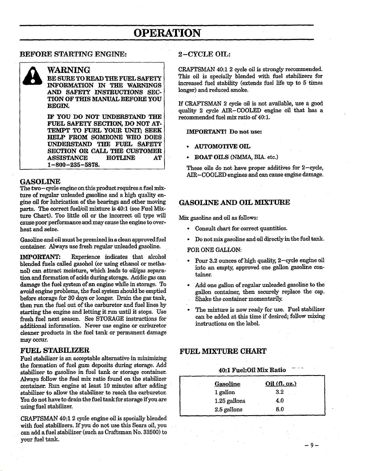
GASOLINE AND OIL iVIIXTURE
Mix gasoline and oil as follows:
• Consult chart for correct quantities.
Gasoline and oil must be premlxed in a clean approved fuel
container. Always use fresh regular unleaded gasoline.
IMPORT _ANT: Experience indicates that alcohol
blended fuels called gasohol (or using ethanol or metha-
nol) can attract moisture, which leads to oi!/gas separa-
tion and formation of acids during storage. Acidic gas can
damage the fuel system of an engine While in storage. To
avoid engine problems, the fuel system should be emptied
before storage for 30 days or longer. Drain the gas tank,
then run the fuel out of the carburetor and fuel lines by
starting the engine and letting it run until it stops. Use
fresh fuel next season. See STORAGE instructions for
ad&'tional information. Never use engine or carburetor
cleaner products in the fuel tank or permanent damage
may occur.
FUEL STABILIZER
Fuel stabilizer is an acceptable alternative in minimizing
the formation of fuel gum deposits during storage. Add
stabilizer to gasoline in fuel tank or storage container.
Always follow the fuel mix ratio found on the stabilizer
container. Run engine at least 10 minutes after adding
stab'_zer to allow the stabilizer to reach the carburetor.
You do not have to drain the fuel tank for storage if you are
using fuel stabilizer.
CRAFTSMAN 40:1 2 cycle engine off is specially blended
with fuel stabilizers. If you do not use this Semrs off, you
can add afuel stabilizer (such as Craftsman No. 33500) to
y_r ._aelta_.
• Do not mix gasoline and oil directly in the fuel tank.
FOR ONE GALLON:
- Pour 3.2 ounces of high quality, 2-cycle engine oil
into an empW, approved one gallon gasoline con-
tainer.
° Add one gallon of regular unleaded gasoline to the
gallon container, then securely replace the cap.
Shake the container momentarily.
• The mixture is now ready for use. Fuel stabilizer
can be added at this time if desired; follow mixing
instructions on the label.
FUEL MIXTLrRE CHART
40:1 Fuel:Oil Mix Ratio .....
t
Oil (ft. oz,) ]
1 gallon 3.2
1.25 ga!lons 4.0
2.5 gallons 8.0
 Loading...