

Craftsman 358798141 Owner’s Manual

operator's
manual
i
MODEL NO.
358.798141-28,0ce
AWARNING:
ReadtheOperator'sManual
and Follow All Warnings
and Safety Instructions.
FailureToDo So CanResuIt
in SeriousInjm-y.
•Always Wear Eye Protection During Operation
,_E/A/,qS[I:RRFT$MRN®_
GAS WEEDWACKER ®
2 Cycle Engine
* Assembly
• Operation
Fuel Mix 16:1
* Maintenance
• Repair Parts
um i ilnf11 if iiii
Sold by Sears, Roebuck and Co., Chk:ago, Ill. 60684 U.S.A.
iii iiii ,i, i_11 , ,i,,,i,,i
66909-2-16987-1-17387 @Sears,Roebuck and Co., 1987
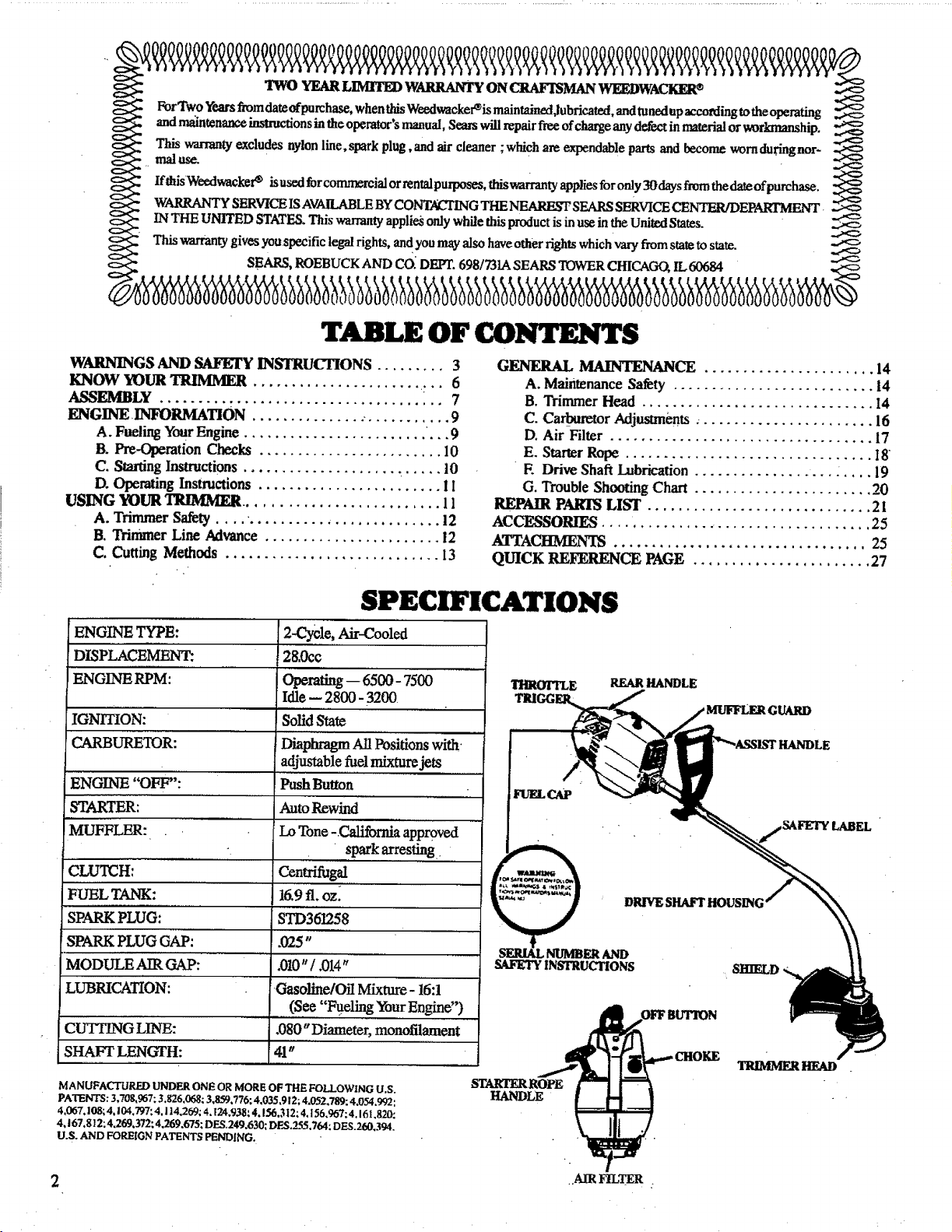
_: TWO YEAR LIMITI_ WARRANTY ON CRAFISMAN WEEDWACKgR®
ForTwo years fromdateofpurchase, when_Weedwacker_is mainlained,luhricated,andtunedup_.eordingtotheoperating _,_
annmamtenaw.e mstmclaons m tlae operators manual, Sears will repair free ofcharge any defect in material or worlmmnship.
This warrantyexcludes nylon line,spark plug,and air cleaner ;which are expendable parts and [_come wornduringnor- ._
IfthisWeedwacker _ isused forco_ial or rental purposes, thiswarranty appliesfor only 30 daysfrom the date ofpurchase.
WARRANTY SERVICEiSAVAILABLE BYCOI'_--TING THE NE_ SEARS SERVICE CENTER/DEPARTMENT
IN THE UNITED STATES. This w_rranty appli_ only while this productis inuse inthe United States.
This warrantygives youspecific legal rights, and you mayalso haveother rightswhich vary from stateto state.
_ SEARS, ROEBUCK AND CO_DEF£ 6981731A SEARS TOWERCHICAGO, IL 60684
TABLE OF CONTENTS
WARNINGS AND SAFEFY INSTRUCTIONS ......... 3
KNOW YOUR TIRJMMER .......................... 6
ASSEMBLY " 7
ENGINE INFORMATION ............... •........... 9
A. Fueling Your Engine ' ,9
B. Pre-Operation Cheeks ........................ 10
C. Starting Instructions .......................... t0
D. Operating Instructions ........................ i I
USING YOUR TRIMMER .......................... 11
A. Trimmer Safety . 12
B. Trimmer Line Advance ....................... 12
C, Cutting Methods ............................ 13
SPECIFICATIONS
ENGINE TYPE:
DISPLACE'MENT:
ENGINE RPM:
IGNITION:
CARBURETOR:
ENGINE "OFF":
STARTER:
MUFFLER:
_CLUTCH:
FUEL TANK:
SPARK PLUG:
SPARK PLUG GAP:
MODULE AIR GAP:
LL_RICATION:
CUTTING LINE:
SHAFT LENGTH:
MANUFACTURED UNDER ONE OR MORE OF THE FOLLOWING U.S.
PATENTS: 3,'/0g.967; 3,826,068; 3,859.776: 4,035,912; 4.052.789: 4.054,992:
4,067. log; 4.104,797:4.114.269; 4,124.938:4,1.56,312;4.156,967; 4,161,820:
4,167.812; 4.269,372; 4.269,675; DES.249.630; DF,S,_$5.764: DES.260.394.
U.S. AND FOREIGN PATENTS PENDING.
2-Cycle, Air-Cooled
28,0c0
Operating-- 6500- 7500
Idle- 2800 - 3200
SolidS_
Diaphragm All Positions with.
adjustable _el mixture jets
PushButton
Auto Rewind
Lo Tone _.California approved
spark arresting
Centrifugal
16,9ft, oz_
STD361258
.025"
,010"/ ,014"
Gasoline/Oil Mixture- 16:1
(See "Fueling Your Engine")
.080 " Diameter, monofilament
'41"
GENERAL MAINTENANCE ...................... 14
A. Maintenance Safety .......................... 14
B. Trimmer Head .............................. 14
C. Carburetor Adjusm_ents ....................... 16
D. Air Filter .................................. 17
E. Starter Rope ................................ 18
E Drive Shaft Lubrication .................. : .... 19
G. Trouble Shooting Chart ....................... 20
REPAIR PAKrlS LIST ............................. 2I
ACCESSORIE_ .................................... 25
A.TTACHMEN'IS ................................. 25
QUICK REFERENCE PAGE ....................... 27
DRIVE SHAFT HOUSING
SAFETY INSTRUCTIONS
TRIMMERI_FA_
STARTER ROPE
HANDLE
2 ,.AIRFILTER
I
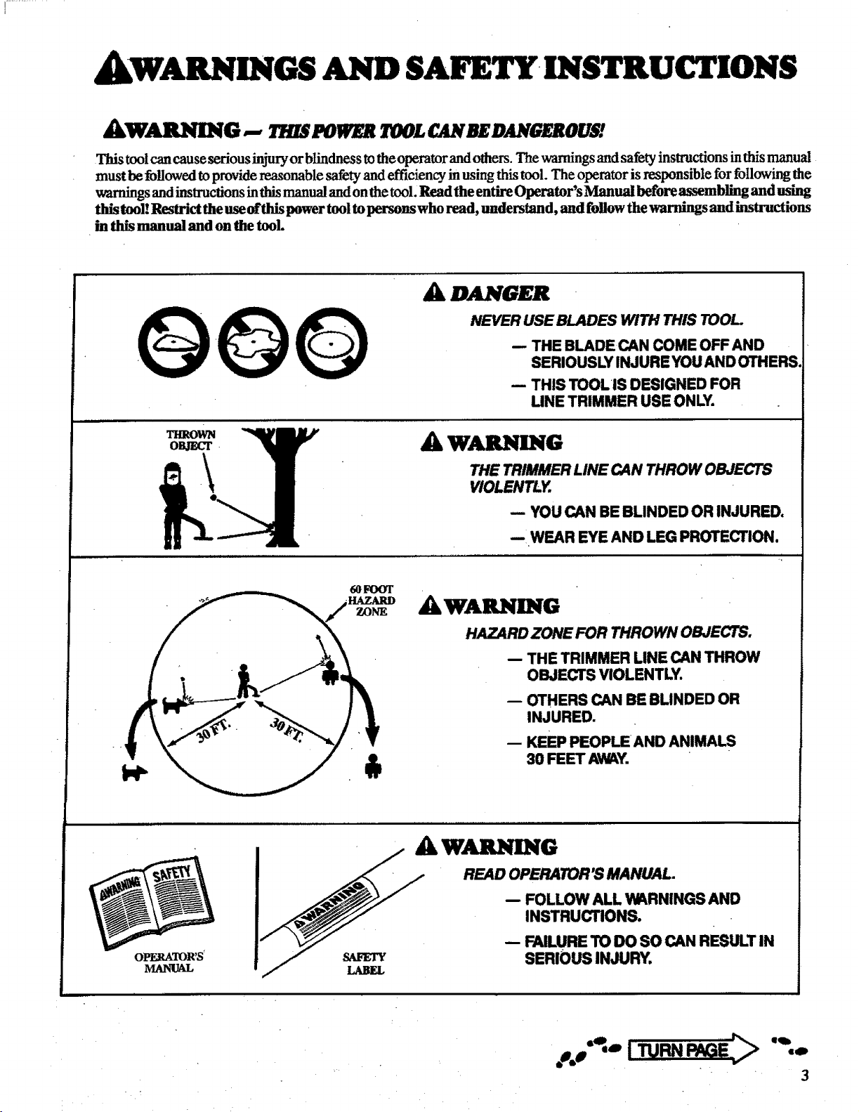
VARNINGS AND SAFETY INSTRUCTIONS
_WARNING -- _ PO_8 I00£ CANBEOANGESOU$!
This tool can cause serious injury or blindness to the operator and others. The warnings and safety instructions inthis manual
must be followed toprovide reasonable safety and efficiency in using this tool. The operator is responsible for foIlowing the
warnings and instructions inthis manual andon the tool. Read the entire Operator's Manual before assembling and using
this tool! Restrict the use ofthis power tool to persons who read, tmderstan d, and follow the warnings and instructions
in this manual and on tl_ tool.
_k DANGER
NEVER USE BLADES WITH THIS TOOL.
-- THE BLADE CAN COME OFF AND
SERIOUSLY INJURE YOU AND OTHERS.
-- THIS TOOLIS DESIGNED FOR
LINE TRIMMER USE ONLY.
THROWN
A WARNING
THE TRIMMER LINE CAN THROW OBJECTS
VIOLENTLY.
-- YOU CAN BE BLINDED OR INJURED.
-- WEAR EYE AND LEG PROTECTION.
WARNING
m
HAZARD ZONE FOR THROWN OBJECTS.
• -- THE TRIMMER LINE CAN THROW
OBJECTS VIOLENTLY.
-- OTHERS CAN BE BLINDED OR
INJURED. •
-- KEEP PEOPLEAND ANIMALS
OPERATOR'S_
AW_G ,
READ OPERATOR'S MANUAL.
-- FOLLOW ALL WARNINGS AND
INSTRUCTIONS.
/ _/ - r_ILU.ETOoOSOCANRESULTIN
.,.,':° iTURNP_:> ".-

WARNINGSAND SAFETY
INSTRUCTIONS
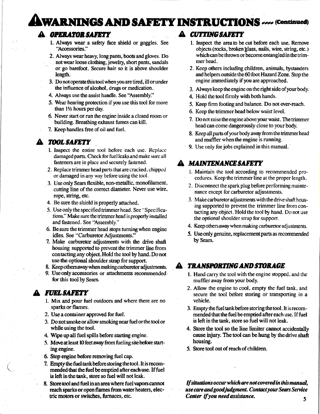
A ar/T G "
1. Always wear a safety face shield or goggles. See
"_,ccessories."
2. Always wear heavy, long pants, boots and gloves. Do
not wear loose clothing, jewelry, short pants, sandals
or go barefoot. Secure hair so it is above shoulder
length.
3. Do not operate this tool when you are tired, ill or under
the influence of ateohol, drugs or medication.
4. Always use the assist handle. See "%ssembly:'
5. Wear hearing protection if you use this tool for more
than 1½ hours perday.
6. Never start or run the engine inside a closed room or
building. Breathing exhaust fumes can kill.
7. Keep handles free ofoil and fuel.
A 700£$AFETY
1. Inspect the entire tool before each use. Replace
damaged parts. Check for fuel leaks and make sure all
fasteners are in place and securely fastened.
2. Replace trimmer head parts that are cracked, chipped
or damaged in any way before using the t_x)l.
3. Useonly Sears flexible, non-metallic, monofdament,
cutting line of the correct diameter. Never use wire,
rope, string, etc.
4. Be sure the shield is properly attached.
5. Use only the specified trimmer head. See "Specifica-
tions:' Make sure the trimmer head is properly installed
and fastened. See "'Assembly:"
6. Besure the trimmer head stops turningwhen engine
idles. See "Carburetor Adjustments"
7. Mal_ carburetor adjustments with the drive shaft
housing supported to prevent the trimmer line from
contacting any object.Hold the tool by hand. Do not
use the optional shoulder strap for support.
8. Keep others away when making carburetor adjustments.
9. Useonly accessories or attachments recommended-
for this tool by Sears.
A. TSANSP0J GAND STORAG£.
A F LSAFE
1. Mix and pour fuel outdoors and where there are no
sparks or flames.
2. Use a container approved for fuel.
3. Do not smokeor allow smoking near fuel orthe tool or
while using the tool.
4. Wipe up all fuel spills before starting engine.
5. Move at least 10feet awayfrom fueling sitebefore start-
ing engine.
6. Stop engine before removing fuel cap.
/."
7, Emptythe fuel tartk before storing thetool, ltis recom-
mended that the fuel be emptied after each use. If fuel
is left in the tank, store so fuel will not leak.
8. Store tool and fuel in an area where fuel vapors cannot
reach sparksor open flames from water heaters, elec-
tric motors or switches, furnaces, etc.
.
Inspect the area to be cut before each use. Remove
objects (rocks, broken _lass, nails, wire, string, etc.)
which can be thrown or become entangled in the trim-
mer head.
2. Keep others including children, animals, bystanders
and helpers outside the 60 foot Hazard Zone. Stop the
engine immediately if you are approached.
3. Always keep the engine on the right side ofyour body.
4. Hold the tool firmly with both hands.
5. Keep firm footing and balance. Do not over-reach.
6, Keep the trimmer head belowwaist level.
Z Do not raise the engine above your waist. The trimmer
head can come dangerously close to your body.
8. Keep all parts of your body away from the trimmer head
and muffler when the engine is running.
9. Use only for jobs expla!ned in this manual.
1. Maintain the tool according to recommended pro-
cedui'es. Keep the trimmer line at the proper length.
2. Disconnect the spark plug before performing mainte-
nance except for carburetor adjustments.
3. Make carburetor adjustments with the drive shaft hous-
ing supported to prevent the trimmer line from con-
tacting any object.'Hold the tool by hand. Do not use
the optional shoulder strap for support.
4. Keepothersaway whenmakingcarburetoradjustments.
5. Useonly genuine, replacementparts as recommended
bySears.
1. Hand carry the t0ol with the engine stopped, and the
muffler away from your body.
2. Allow the engine to cool, empty the fuel tank. and
secure the tool before storing or transporting in a
vehicle.
3. Empty the fuel tank before storing the tool. It is recom-
mended that the fuel be emptied after each use. If fuel
is left in the tank, store so fuel will not leak.
4. Store the tool so the line lirniter cannot accidentally
cause injury. The tool can be hung by the drive shaft
housing.
5. Store tool out of reach of children.
If situations occur which are not covered in this manual,
use care and goodjudgment. Contact your Sears Service
Center ifyou needassistance. 5
III III I I IIII II I II IIIII II Ill I] I IIII . IIIIIIIIII II
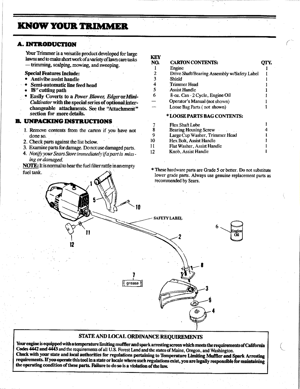
r_o w YOUR TRIMMER
it iiiiiitlttt lit I tit it t tl It ttl I t
A. INTRODUCTION
YourTrimmer is aversatile product developed for large KEY
lawnsand to make shortwork ofa-cariety of lawncare tasks NO.
-- trimming, scalping, mowing, and sweeping. 1
Special Features Include: 2
• Antivibe assist handle 3
• Semi-automatic line feed head 4
• 18" cutting path 5
• Easily Coverts to a Power Blower, Edger orMini- 6
Od/ivator with the special series of optionalinter- --
changeable attacinnents. See the '_l_achrnent"
section for more details.
B. UNPACKING INSTRUCTIONS
I. Remove contents from the carton if you have not
done so_
2. Check parts against the list below.
3. Examine parts for damage. Do not use damaged parts.
4. Notify your Sears Store immediately_tf apart is miss-
7 Flex Shaft Lube 1
8 Bearing Housing Screw 4
9 Large Cup Washer, Trimmer Head 1
10 Flex Bolt, Assist Handle t
I I Flat Washer, Assist Handle 1
12 Knob, Assist Handle 1
ing or damaged.
NOTE: It isnormal to hear the fuel filter rattle inan empty
fuel tank.
* These hardware parts are Grade 5 or better. Do not substitute
CARTON CONTENTS: QTY.
Engine 1
Drive Shaft/Boring Assembly w/Safety Label I
Shield 1
Trirmner Head 1
•Assist Handle 1
8-oz. Can -2 Cycle, Engine Oil I
Operator's Manual (not shown) 1
Loose Bag Parts ( not shown) 1
*LOOSE PARTS BAG CONTENTS:
lower grade parts. Always use genuine replacement parts as
recommended by Sears.
SAFETY LABEL
STATE AND LOCAL ORDINANCE REQUIREMEN_
Yourengine is equipped witha temperature limiting muffler and spark arresting screen which meets therequirements of California
Codes 4442 and 4443 and the requirements of all U.S. Forest Land and the statesof Maine, Oregon, and _shington.
Check with your state and local authorities for regulations pertaining to Temperature Limiting Muffierand Spark Arresting
requirements. Ifyou operate this tool inastate or locale where such regulations mist, you are legally responsible for maintaining
the operating condition of these parts. Failure to do so is a violation of thelaw.
g,r,,,i
IHII[II[IIIVJIJII I III I II I IIIIII I . IIII
,m,l,Wll,_llUll
A.QQi_.]Iu[IIll .V _t°°l is received assembled, repeat all steps in this'section to be sure assembly is correct
•,.v-...-...,,--.., and is adjusted for the Ol_mtor.)
iiii IIIIIIIIII ii I iiiiiiiiiiii iiiii i iii IIII i iiiiiiiiiiiiiiiii
A. PREPARATION
k
• This Operator's Manual has been developed to help you
assemble the tool and to provide its safe operation. It is
important that you read the entire manual to become
familiar with the tool before you begin assembly.
1. READ YOUR OPERATOR'S MANUAL
Iltli_tlltlllIII IIIIIIII Ill[ IIIH IIIIImHI i
B. ASSEMBLY STEPS
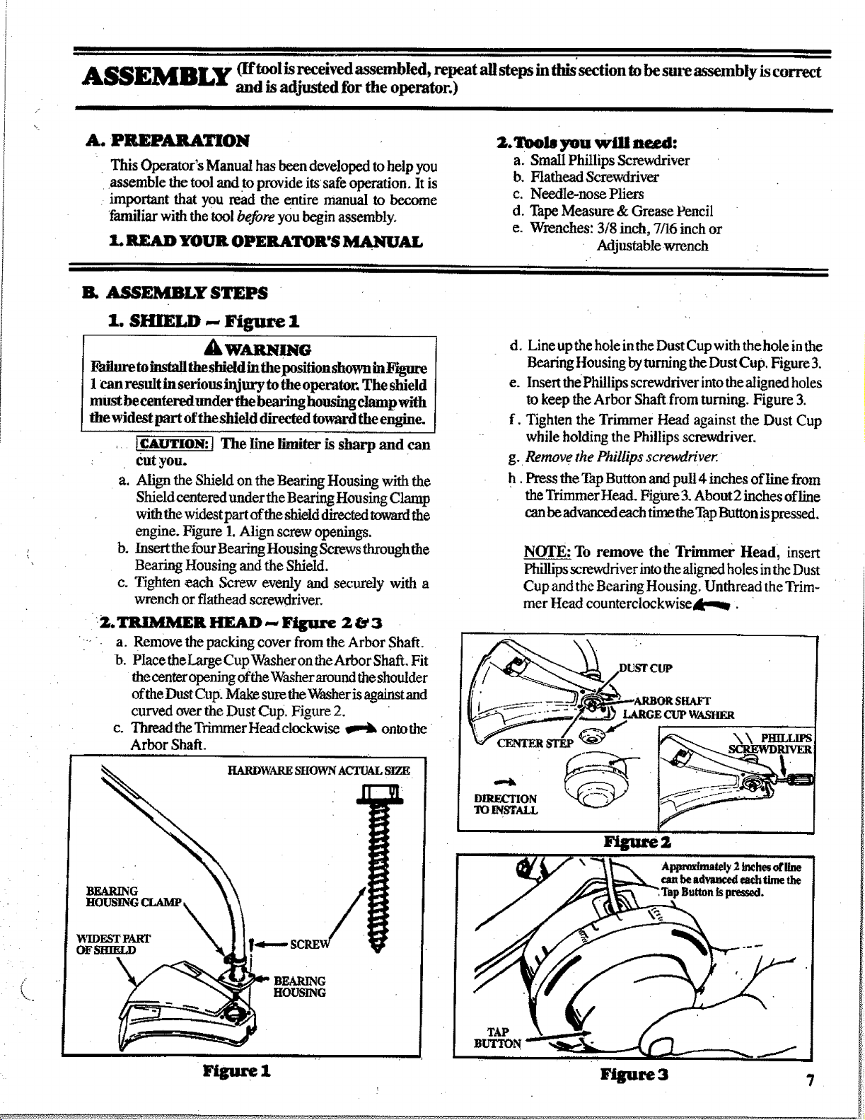
1. SHIELD _ Figure 1
A WAR mG
Failure to install the shield in theposition shown in Ytgm-e
I can result in serious injury to the operator. The shield
must be centered under the b_ housing clamp with
the widest part of the shield directed toward the engine.
_ [CAI/TION: ] The line limiter is sharp and can
Cutyou.
a. Align the Stfield on the Bearing Housing with the
Shield centered under the Bearing Housing Clamp
with the widest part of the shield directed toward the
engine. Figure 1.Align screw openings.
b. Insertthe four Bearing Housing Screws through the
Bearing Housing and the Shield.
c. Tighten each Screw evenly and securely with a
wrench or flathead screwdriver.
:2.TR/MMER HEAD -- Figure 2 &3
a. Remove the packing cover from the Arbor Shaft.
b. Place the Large Cup Washer on the Arbor Shaft. Fit
the center opening ofthe Washer around the shoulder
ofthe Dust Cup. Mal_ sure theWasher is against and
curved over the Dust Cup. Figure 2.
c. Threadthe TnmmerHeadclockwise _ ontothe
Arbor Shaft.
2. Tools you Will need:
a. Small Phillips Screwdriver
b. Flathead Screwdriver
c. Needle-nose Pliers
d. Tape Measure & Grease Pencil
e. Wrenches: 3/8 inch, 7/16 inch or
Adjustable wrench
" ii
d. Line up the hole in the Dust Cup with the hole in the
Bearing Housing by turning the Dust Cup. Figure 3.
e. Insert the Phillips screwdriver into the aligned holes
to keep the Arbor Shaft from turning. Figure 3.
f. Tighten the Trimmer Head against the Dust Cup
while holding the Phillips screwdriver.
g. Remove the Phillips screwdriver.
h. Press the Tap Button and pull4 inches of line from
the Trimmer Head. Figure 3. About 2 inches ofline
can be advanced each time the Tap Button is pressed.
NOTE: To remove the Trimmer Head, insert
Phillips screwdriver intothe aligned holes in the Dust
Cup and the Bearing Housing. Unthread the Trim-
mer Head counterclockwiseA, m_.
IlililIliilllllI I I I I
tL4_RDWARESHOWNACTUALSIZE
BEARING
WIDESTPART
OFSItIELD
/
i i iiii ii iii i._
HOUSING
Figure 3 7
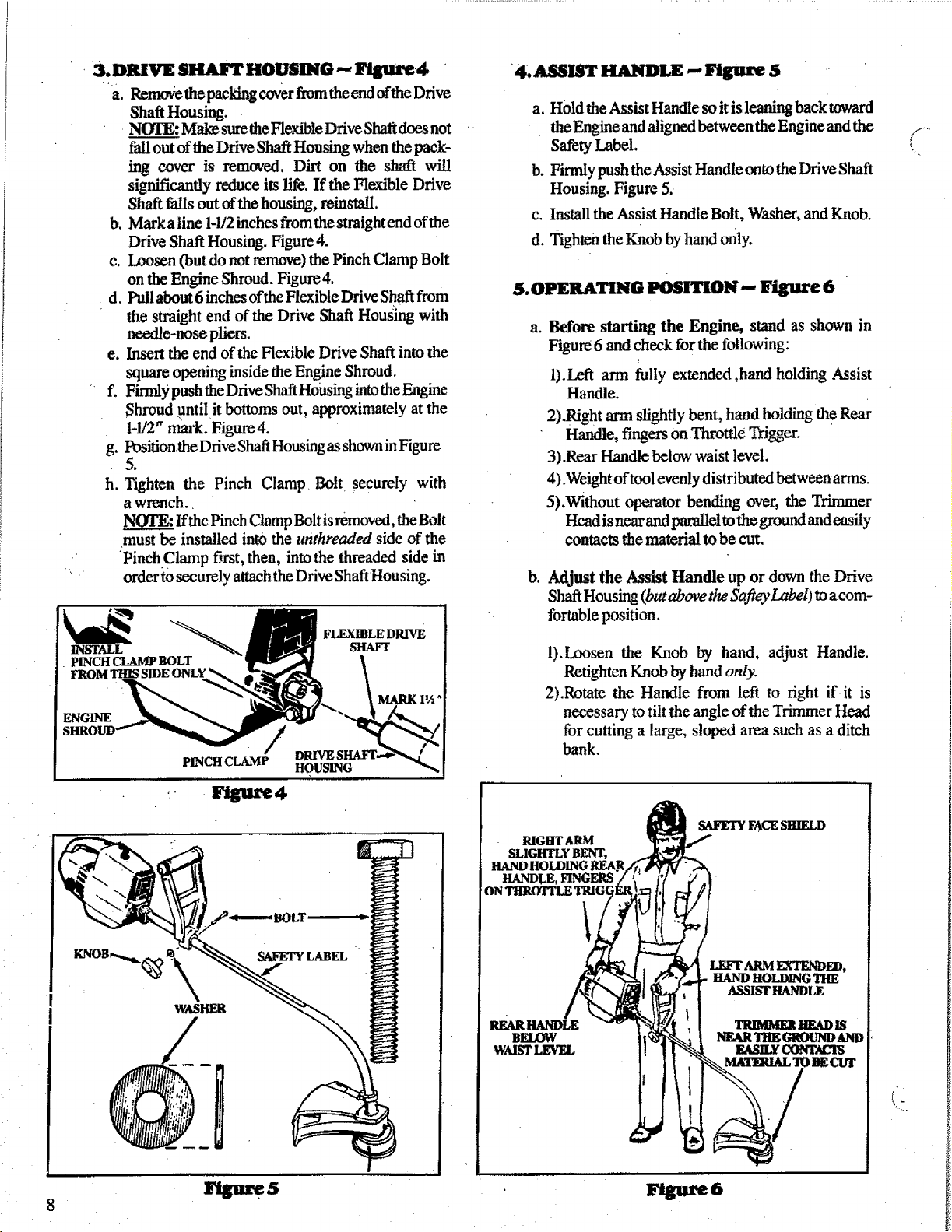
'+ 3. DRIVl_ SHAFT HOUSING _ Figure4 .+
a. Removethe packing cover from theend ofthe Drive
Shaft Housing.
, NOLO: Make sure theFlexible Drive Shafl does not
fall out of the Drive Shaft Housing when the pack-
ing cover is removed. Dirt on the shaft will
significantly reduce its life. If the Flexible Drive
Shaft falls out of the housing, reinstall.
b. Mark aline 1-1/2inches from the straight end of the
Drive Shaft Housing. Figure 4.
c. Loosen (but do not remove) the Pinch Clamp Bolt
Onthe Engine Shroud. Figure4.
d. Pull about 6 inches of theFlexible Drive Shaft from
the straight end of the Drive Shaft Housing with
needle-nose pliers.
e. Insert the end of the Flexible Drive Shaft into the
square opening inside the Engine Shroud.
f. Firmly push theDrive Shaft Housing intothe Engine
Shroud untilit bottom s out, approximately at the
1-1/2" mark. Figure 4.
g. Position.the Drive ShaftHousing as shown in Figure
5.
h. Tighten the Pinch Clamp Bolt securely with
a wrench.+
NOTE: If the Pinch Clamp Bolt is removed, the Bolt
must be installed into the unthreaded side of the
:PinchClmn p first, then, into the threaded side in
order to securely attach the Drive Shaft Housing.
_1_ _ FLF_XmLEDRIVE
INSTALL SHAFI"
. PINCH CLAMP BOLT
FROM
MARK 1½ _
ENGINE
PINCH CLAMP HOUSING
4.ASSIST HANDLE --Figure 5
a. Hold the Assist Handle so it is leaning back toward
theEngineand aligned betweenthe Engineandthe
Safety Label.
b. Firmly push the Assist Handle onto the Drive Shaft
Housing. Figure 5.
c. Install the Assist Handle Bolt, Washer, and Knob.
d. Tighten the Knob by hand only.
&OPERATING POSITION,- Figure 6
a. Before starting the Engine, stand as shown in
Figure 6 and check for the following:
l).Left arm fully extended ,hand holding Assist
Handle.
2).Right arm slightly bent, hand holding+the Rear
" Handle, fingers onThrottle Trigger.
3) .Rear Handle below waist level.
4).Weight of tool evenly distributed between arms.
5).Without operator bending over, the Trimmer
Head isnear andparallel to the ground and easily.
contacts the material to be cut.
b. Adjust the Assist Handle up or down the Drive
Shaft Housing (butabove the Safiey Label) to acom-
fortable position.
l).Loosen the Knob by hand, adjust Handle.
Retighten Knob by hand only.
2).Rotate the Handle from left to fight if it is
necessary to tilt the angle of the Trimmer Head
for cutting a large, sloped area such as a ditch
bank.
if ....
++
+: , Ftgure4
\
WASHER
RIGHT ARM
SLIGHTLY BENT,
HANDLE, FINGERS
REARHANDLE
BELOW
WMSTLEVEL
SAFETYFACESHIELD
LEFT ARM EXTENDED,
HAND HOLDING THE
ASSIST HANDLE
*+,...
'.
m
illiilliiiiillii•HimiiiiiiIIIH II II IllllllllllllIIIIII Illllllll
, iii iiiiii illl .
ENGINE INFORMATION
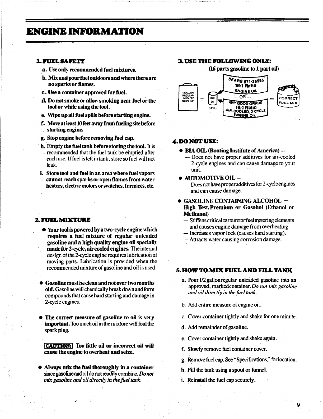
3. USE THE FOLLOWING ONLY:
a. Use only recommended fuel mixtures.
b. Mix and pour fuel outdoors and where there are
• no sparks or flames.
c. Use a container approved for fuel.
;d. Do not smoke or allow smoking near fuel or the
tool or while using the tool.
e. Wipe up all fuel spills before starting engine.
f. Move at least 10feet away from fueling site before
starting engine.
g. Stop engine before removing fuel cap.
h. Empty thefuel tank before storing the tool. It is
, recommended that the fuel tar& be emptied after •
each use. If fuel is left in tank, store so fuel will not
leak.
i. Store tool and fuel in an area where fuel vapors
cannot reach sparks or open flames from water
heaters, electric motors or switches, furnaces, etc.
2. FUEL MIXTURE
• Your tool is powered by atwo-cycle engine which
requires a fuel mixture of regular unleaded
• gasoline and a high quality engine oil specially
•made far 2-cycle, air cooled engines. The internal
design of the 2-cycle engine requires lubrication of
moving parts. Lubrication is provided when the
recommended mixture of gasoline and oil is used.
,t.no NoTUSE:
• BIA oIL (Boating Institute of America) --
-- Does not have proper additives for air-cooled
2-cycle engines and can cause damage to your
unit. "
• AUTOMOTIVE OIL-
- Does not have proper additives for 2-cycle engines
and can cause damage.
• GASOLINECONTAINING AI_OHOL --
High Test, Premium or Gasohol (Ethanol or
Methanol)
-- Stiffenscritic'_ carburetor fuelmetering elements
and causes engine damage from overheating.
-- Increases vapor lock (causes hard starting).
Attracts water causing corrosion damage.
5.HOW TOMIX FUEL AND FILL TANK
(16 parts gasoline to 1 part oil)
Gasoline must be clean and not over two months
old. Gasoline will chemically break down and form
compounds that cause hard starting and damage in
2-cycle engines.
• The correct measure of gasoline to oil is very
important. Too much oil inthe mixture will fou!the
spark plug.
]CAUTION:[ Too little oil or incorrect oil will
cause the engine to overheat and seize.
Always mix the fuel thoroughly in a container
since gasoline andoil do notreadily combine. Do not
mix gasoline and oil directly in the fuel tank.
a. Pourl/2 gallon regular unleaded gasoline into an
approved, markedconminer.Do not mix gasoline
and oil directly b7the fi_el tank.
b. Add entire measureofengine oil.
c. Cover container tightly and shake for one minute.
d. Add remainder of gasoline.
e. Cover container tightly and shake again.
f. Slowly remove fuel container cover.
g. Remove fuel cap. See "'Specifications:" for location,
h. Fill the tank using a spout or funnel.
i. Reinstall the fuel cap securely,.
9
 Loading...