

Page 1
IMPORTANT MANUAL Do Not Throw Away
Operator’s
Manual
Model No.
358.707922-32CC
358.797950~22ec
358.797961-22CC
35a797982~32ce
A WARNING:
Bead faheC^erateat^sManaal aad
BoSmAB Safely
ISStìtìction^’'ÌÌÌ0Ì^- f o Do So
Can Besnlt in Serious Injury.
Always Wear Eye Froteetìon
EMi/CRflFTSMflN
GAS POWER BLOWER
2 Cycle Engine
• Assembly
• GperatioB
Fuel Mix
• Maintenance
• Repair Parte
Sold bj 60684 USA
530-081829-1-06/17/93 A 'tOClQ £3Ylfl fin
Page 2
LMTED WARRANTY ON CRAFTSMAN FOWER BLOWER
WARHANTS KBMOD: One Year - Models 368.7979S0 & 358.797961
Per tim Wan^ty Period spoiled above from the dale of parchase, when tfe Power Blower is maintained, btbicated, and toned up
Й
ajwronjg to toe w^tmg and mamtenaaee mstruct ions in the operator's maimal, Sears will repair free of Ашгве any defect in mate
rial or wwkmanship. ’ '
This warranty excludes bbwer tubes, spark plug, and air deansn which are expendable pans and become worn duriogniMriiud rise.
If this Power Blower is used for commercial or rental purposes, this wacmity applies for 90 days.
Mbrí I ilv ТИБ UNITED STATES. This warranty applies only white this product is in use in the United States.
This warranty gives you spenCc legal rights, and you may al^ have othm- rights which vary from state to swte.
Two Years - Models 358.797922 & 3SS.797982
THE UJCrr TO THE ЖДЕЕ5ТЗЕАВ8 SERVICE CEK'TERBIPAET-
SEARS, ROEBUCK AND CO./PEPT. D/817WA, HOFFMAN ESTATES, IL 69179
TABLE OP CONTENTS
WABNmGS AND SAFETY INSTRUCTIONS
A. Ogierator Safety ..................
B. Operating Tips*--Blower .
C. Operating Tips—Vhcumn
jD. Pre-operation Checks ..,.
., 3 GENERAL MAINTENANCE.........................
6
.. 8
.. 8
9
A. Air Filter
B, PuelTfflik ............
C. Starter Rope ... ,'t
D. Storage - -
F. TEotiiSa ShontiTie'Chart. ’...
ACGESS€№S
REPAIR PARTS LKT -
QinCK-REFERENCE PAGE..........................
PARTS AND SERVICE
..........
.................................
........................
................................
........
................................
.................................. ..
............
...........
......................
......................
..
.............
.........................
........
...............
.........................
..................
.........................
..........;:i it
........................12
.........................
****-_-,.,,*, 16
BadeCerver
SPECIFICATIONS
10
10
ib
10
12
13
ENGINE TYPE:
DISPLACEMENT;
2 Cycle Air Cooled
22cc-- *
Model 368.797950
Model 358.797961 ,
32cc—
Model 358.797Se2
Model 358.797982
ENGINE RPM:
Operating—^7000 -7600-
All Models
Idle—3800-4600—
AH Models
IGNITION: _
CARBURETOR:
ON/OFF SWITCH:
STARTER:
Solid State
AU Position Diaphragen SPARK PLUG GAP:
Positive Rocker Switch MODULE АШ GAP:
Auto Rewind
FUEL TANK: l8;6fl.OZ.
JjaoBTAciiirtd юЛг я» вг ею« oTtb* Мэтвв* US, P»|«ot* <,«4.706; 4,ti3,371: <eí4,146:
SE »,»0;<7$S.IS$; <4Ce.l0«; 0299.074. Othe
VS. tai
fongu »Мент peater ‘
MUFFLER;
AIR VELOCITY:
AtR VOLUME:
ШШКРШСк
LUBRICATION:
Lo Tone .
155 mph—
Model 358.797950
Model 358.797961
170 mph**—
. . Moda^.797922
Model 358.797982
350 cuil-Anin.—
Model 358.797950
Model 368.797961
360 ca.ftAnin.—
Modd35U97922
Midel ^1^982
CU-ST(Cat, No. n-85853)
,025” .
.010”-.014”
Gaso£ne/Oil №xture—
See “Fu^gYourEngme”
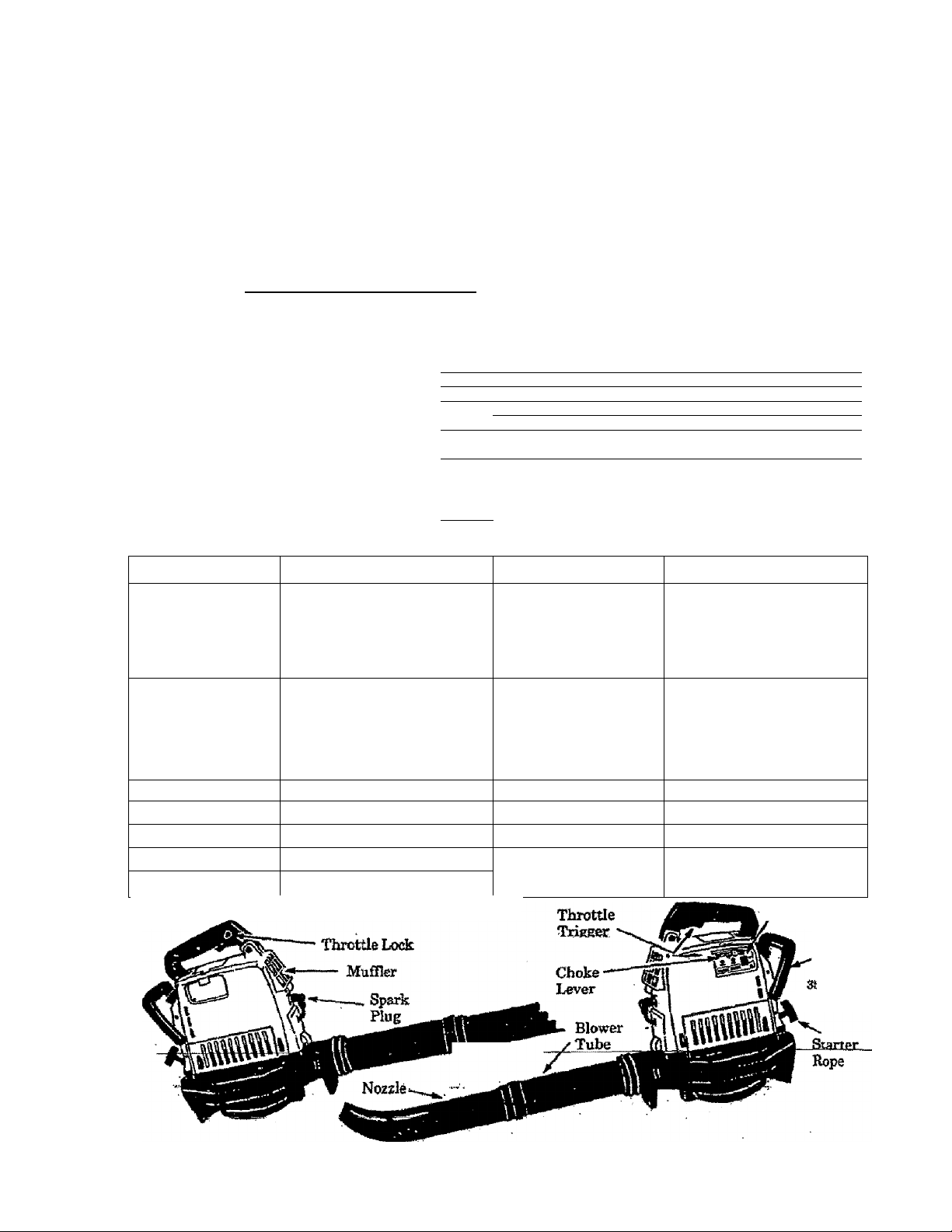
ON/OPF Switch
Rear
Handle
(Model
18,797982
ОКШ
Page 3

•Ufa
A WARNINGS AND SAFETY INSTRUCTIONS
Failure io follow all Safely Rules and Precauiions can result in serious injury.
A. KNOWYOUK UNIT
1. Read yotir Operator’s Manual carefully rnitil
you completely understand and can follow a]] warn
ings and safety instructions before operating unit.
Z, Restrict yeur unit to users who understand and
will follow all wartjiixp and safety instructions in .
this manual.
B. FLAN AHEAD
l;;,Alzc<tys wear eye protection to prevent rocks or
debris from being bhwn or ricocheting into ^'e$ and
face which can result in blindness andfor other seri
ous injury.
2. Always wear a ret^irator or facemaslc when
working with the unit in dusty enviromnents.
3. Always wear hea^vy, long pscDts> boots^ and
gloves. Do not M barefoot or wear short pants,
sandals, jewelry, loose clothing, or clothing wtth
loosely han^g straps, ties, tassels, etc.; they can be
caught in moving Secure;^sdr so it is above
shoulder length, Beingfuily covir'ed will bdp pro
tect you from pieces of tooc plants suidi as poison
ivy ttffown by the blade, which could be more of a
hazard than touching the plant itself
4. Do not operate the unit when you are tired, ill,
upset, or tf you are under the influence of alcohol,
dmgs, or medication.
5. Keep children, bystanders, and animals away
from tHe work area a minimum of 30 feet wkmstarting or operating the unit.
6. Inspect the axeahefore starting the unit. Re
move all debris and hard objects such as rocks,
^ass, wire, etc. that can ricochet, be thrown, or oth-
. «wise cause injury or damage during operation,
C. HANDLE FUEL WTTH CAUTION
1. Eliminnte all sources of sparks or flame (in
' duding smoMng, open flames, or work that can
cause ^arks) in areas where fuel is mixed, poured,
or stored.
2. Mix and pour fuel in an outdoor arem; store
fhel in a cool, dry, weB—ventilated place; use an ap
..,. proved, marked cmtainw for.all |p^;paposes. ^ .
not aasdfee whRe handlii^^teror wnite ’
'Operating the unit. -
4. Do not ^ fuel task while engitie is running.
3. Stop the engme before reinovragthe fbel cap,.
Allow the engine to cool before reeling.
6. Wipe up aUfuel spills &^rc starting engine.
7. Move at least 10 feet away fkom ftiel and fuel
ing site before starting the mtgine.
p. OPERATE YOUB UNIT SAFELY
1. Stop the engine before opening the vacnunt
inlet door or attempting to insert or remove the
: vacuum tubes. Ji^^nginem^^tg^pped and the
impeller bladekiwphget toipi|3gi^^ serious
inijuiy from therotatinghlades.
2. Inspect the entire unit bef>re each use for worn,
loose, missing, or damaged parts. Do not use until
the unit is in proper working order.
3. Keep the outside surfaces free of oil and fueL
4. Never start or run unit inside a closed room
6. Never use for spreading dhemicals, fertiliz
ers, or any other material which may contain toric
substances.
7, Do not set the unit on any surface except a
dean, hard area to start the engine or while
the engine is running. Debris such as gravel,
sand, dust, grass, etc. could picked up by the air
intake and thrown out through the discharge open
ing, damagingthe unit, property, or causing serious
injury to bystanders or the operator.
S, Avoid dangerous enviromnents. Do not use in
unventilat^ ateas or where erqplteive vapors or
carbon monoxide build up could be present.
3. Avoid situations which could set the collec
tion bag on fire. Do not vacuum discarded cigars
or cigarettes or ash'from fireplaces, barbecue pits,
brush pües, etc. To avoid spreading fir^ do not use
blower near leaf or brush fires, fireplaces, barbecue
pits, ashtrcys, etc.
10, Do not overreach or use from unstable sur
faces suds as ladders, trees, steep tuoflops,
ete. Use extra care when cleaning on stairways.
Keep firm footing and balance at all tiroes.
11. Never placé objects inside the blower tubes;
always direct the blowing debris away from people,
animals, glass, and solid objects such as trees, auto
mobiles, walls, etc. The force of air can cause rocks,
dirt, or sticks to be thrown or to ricochet which can
hurt people or animals, break glass, or cause other
damage. Do not allow ^ unit to be used as a toy.
12, Never place any object in the mr intake open
ing as this could restrict proper air flow and cause
damage to the unit.
13. Mever ran unit without the proper^equljj^
ment attached. When used as gblower, always in
stall ablowertube, When used as a vacutan, always
install vacuum tubes and collection bag assembly.
. 14.Use only for jobs esplainedln this manual.
E.MAINTAIN YOUR UNIT PROPERLY
1. Have all maintenance other than the recommended
promkîresdescïfliedhîliié Gperatoris Manual per
. formed by your Sears Serrice Center.
2. Disconnect spark plug before performing
maintenance except for carburetor ^nstment.
3. Use only genuine replacement parts as xedommendedl^ Sears to avoid creating a hazard and/or
voiding your wairanty-
4. Check air intake openings, blower tubes, el
bow tube, and vacuum tabes frequently; al~
, ivayswithfrieenj5bttestopped, Keepventsandtubes
free of debris which can accummate and restrict
.. ror Sow. ;
5. Befoi^ storing the unit, use up fuel left in
carbaretor and mellhies by starting the engine and"
letting it run until it stops;. See “Stor^” section.
3. Do not use any accessory or attacbiEent other
thanthoserecommendedbySearsforusewithyour
7. Dd not store the unit or fiiel in a closed area
3. To avoid sliock from static electricity, do not*
wear robber or anv other insulated gloves whileotte.^,. ,
eratiag the unit. . .ss
If situations occur which are not covered in this manual, use care and good Judgement.
Contact your Sears Service Cenieg/Deparpnent if you need assistance.
from hot water heaters, dectricmotois or switches,
.furnate§.etc, , ,
»;• ■ Storb Ш ai dry area out of reach of children.
Page 4
KNOW YOUR UNIT
A.INTEODOCTION
Your blowor is a hi^ performance product
for tou^ jobs.
Special'Eeatures include:
• for fme-handed operation.
• DixectBrive.
a Viferation—Dampened Handle.
• Wei^t - 12 lbs.
• Comrenientx^rii^t storage.
• ATailable Gutter Attachmmt Kit #358.79992
B. UNPACKING INSTRUCTIONS
1. Hemove contents from, the carton if you have nc^
done so. ,
2. Check parts against the Carton Contents List
3. Bbcamine parts for damage. Do not use
parts.
A mUfyyofO'SeanSmAi^CaderlEhpftrtmmtirmne-
NOTE
.............
empty fiiei tank.
It Your unit is factory equipped wiUi a vibra-
t—dampened handle whida causes the handle to
appear to be loose. This condition Is normal
the Safety Notice at the bottom of this page.
NQTEi. Your u^'lm been factory tested and the car
buretor precisely adjusted. '№e3№fore,iti&possib!e
to smell gasoline or to find a drop of ou/fuel readne
on the muffler.
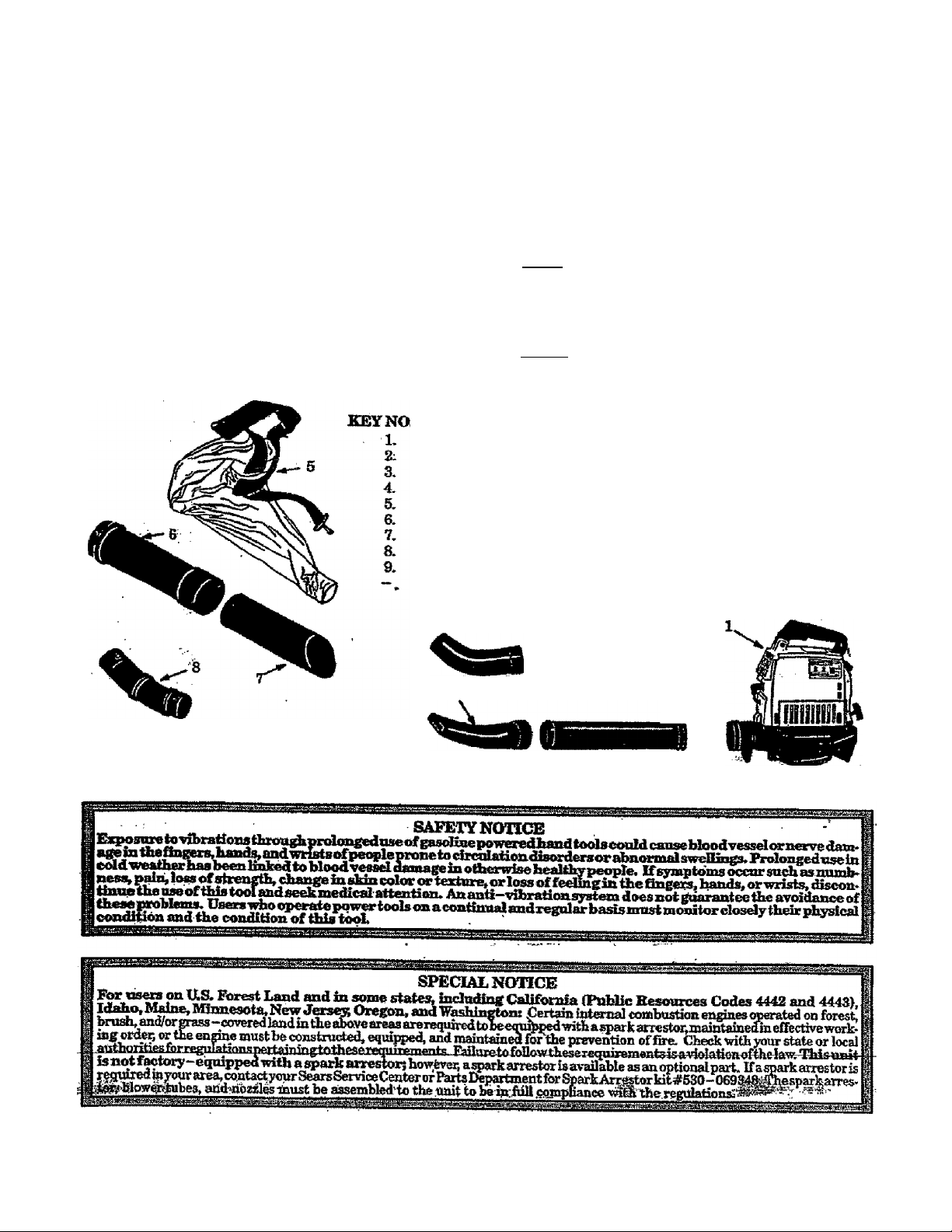
CARTON GONTENTS
Bowerhead ‘'1
Blower Tvdie i
Concentrator Nozzle 1
flare Nozzle 1
Vacuum Collection Bag 1
Upper VacBum Tube 1
Lower Vacuum l\ibe 1
Elbow Tube 1
2-cyde En^e Oil i
Operator's Manual (not shown) 1
........
rattle in an
<
Models '
3Sa797922Tfe3SSli9lS82
Models
358.797950
358,797961
2
V
Page 5
ASSEMBLY
A.PREFARATION
%nxr Operetoir^s Maxniid has been devejo{^ to h^
jpou assemble the uultand toimderstaitd its safe opera'
tkm.- It is iiai>ortai2t that you read your manual com
pletely to become familiar with the unit hefore you be-
t. BEAD YOliBOPERATOa'S MANUAL.
2» The <mly tool required is a standard screwdriver.
NOTE; Toease assembly; lubricate lockingtrfts before
assembling tubes.
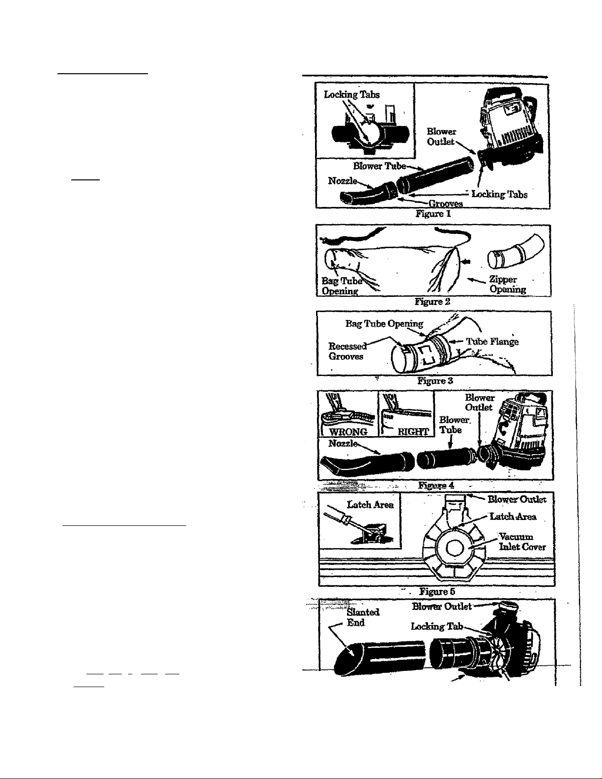
B'BLOWER TUBE ASSEMBLY
L Locatethetwolockingtabsonthesideoftbeblower
tube. Figure 1.
2. AMgn the grooves on the hozrle with the locking
tabs on the blower tube and push the nozzle onto
the blower tube.
3. Tom the nozzle clockwise until the parts snap into
. place and are firmly ti^teued.
4. Align Grooves on the Blower Tube with Locking
Tabsiathe Blower Outlet 0?gure 1, inset) andpu^
the Blower Tube into the Blower Outlet.
5. Tom the Blower Tidie clo«ikwise until the parts
snap into place and are firmly tighttaied-
a VACOtJM BAG ASSEMBLY
1. ' Opfio. the zijmer on thelai^ end of the vacurunhag.
2. Insert the Elbow Tube, grooved end first, throu^
_ the z%)p^ tpeningin the vaonim bag (Figure 2).
Then, pu^ the grooved end of the Elbow Tube
throughthebagtubecpemngin&eotfaerendofthe
bag. Kg^es2&3. Imke sure the bagtobeqpenmg
. is Qush against the tube flimge. Figure 3.
'3.- caosetbezipt^onthebag. fekesuretheKtoperis
'»dosed compLeteb^ and the zipper seam is tm£edto-
-ward the inside of the bag. Figure 4 Onset).
D. VACUUM TUBE ASSEMBLY
AWABNING
Stop the engine before opening the vactmm inlet
ntntobes. Theeni^eniastbestoppecland&elni'
pdQ^. blades no longer torrilng to acvoid serions
injgry fifom the rotatingbladeg.
1. Remove the blower tube fimm the engine. Figure 4
2. Settheunit,bloweroutletup,onaflBtsuifaeeG^-
ure 3). Open the vacuum imet cover as follows:
a. Irwert a screwdriver into latA area. Figures,
h. -Gently twist the tip of tiie screwdriver and oj^
&e vacuum inlet <»ver with your other hand.
3i HoH open vacuum inlet^vCT ^d aliga ^e^tr^
side the vacumn inlet. Figure 6. Insert upper
vacutna into the vacuum miet; twist the upp®* vac
uum tube docfcwise imtil parts snap together.
4 Assemble the vacuum tubes by aligning the slanted
end of the lower vacuum tube witfi the Wowcroutlet
as shown in Figure 6,_Push the two tubes together
-until thcy are snug. Ftgui'g-fe 7
NOTE? The bottom end of the lower vacuum tube is
. ;?^,cut:at an angle. Mafes siire slanted end of vacuum
tuhe h aligned with blower ouilet. Figure 6.
Vacuum M?^.Covkc ; ; i', -'^tcuum.Ialet
-----
....
...............................
.............
------------
Page 6

S- To attach lite vacuum bag, aSgn. the grooves 611 the
elbow tube with the lod&g tabs imsde the blower
qutìet. Figure 1 (inset). Be sure to align the dot on
the dbow tube wth the dot on ihe blower honrfng.
Insért elbow tube into blower outlet; twist elbow
tube counterdockwise until parts snap together.
6. A#ist the vacuum collection bag at the dhow tube
to remove any twists. Figures.
E. STOULDm STRAP ^JUSTMEìSÌT
_
„----------Collection Bag are positioned on your rigfat'-hand
side. sigure S. .
2.
Place collecticm bag strap around, your back and
over your left shoulder. Snap collection bag hook
onto the strap retainer in the top handle. Figure s.
3. EJctendyourri^tanutowardtherearofthecoUection bag. Figure 8.
4. Adjust the Moulder strap until the collection bag/
shoulder strap seam liesoetween your thun^ and
index finger. Figures.
6. Maj^ sure the shoulder strap is adjusted to aQow a
. Ìréèfibwofairfronitheelbowtube, iiguraS. iftbe
Bag is kinked, the unit will not operate properly.
---------
------—.----------
. Make surethe Blower Outlet and
prilli posi-
ube on the
E BLOWEK CONVERSION
1. Stop the engine. Allow the engine to cooL
2. Eemove the vacuum tubes and coliectfon bag as
sembly.
^3. Secure the vacuum inlet cover. Make.sorelhat the
latch on the vacuum islet ^c^ii^fastened.
4. BeinstaUtheblowerhibesasshowninme^Blower
Tube Assembly** section.
BoddngTabs
Figure?
Collection Bag/
Shoulder ^ap
Seam '
SteapBetainer
■■ ■ -
Figured
USING YOUR UNIT
A. OPERATOR SAFETY
A WASHING
Bo not assemble or disassmshle vacuum tuba
wiiilethean^^eisriiigmmg. Insextingorremov*
ingthe vacoftm t^e while the engine is rtmniros
can resnlt‘'1n serious injury. Always stop the mxgine find discoimect the spmrh plug l^ore un-
oi^^^^lleciaon. ba^.
As a blower, the unit is des^ned to sweep ^ri^
gras%^^:j^w^@avss, small tensor light snow. It can
alsp № HHtfast dryingwet outhmraix^sudbasa
sidews^ carport, etc.^ Never use for spreadi&g
' misting dhemicals, fertilizer^ or any Pthmr maim-
aib which may contain toxic substancés. As a vaca-
tempt to vacuum stones, gravd, nmtal, brokmi ^iss, enr
ai^ other debris which rnay cause damage to tbehn^-
texi Do not atimpt to vaetam water or any oth&‘lig-’
tads- *l%umundi%wat№orQtherU<piichiwjllcausedam-
s^totheeii^ine. Avmdsituatiora that could catch the
collection bag on-fire. Do not operate near an open
not vacuum discardbd dears or ctearettes or
ashfrcTO fireplaces, baihecue pits, brush p^, etc.
h Beadi your Operator's Hanttial. sure you
oompletdy understand and can follow all warnings
and safety insbructious in the manual before operat
ing die unit.
2. Always wear a respirator or facemash when
workhig in dusty environments.
-^rAJflPSys wear eye protection to prevent roihs or
d^rts from betttg-haifea.or deecheting into ey^s
aSS face which cairifimt in blindness or other sm-
ous injury.
Rear Handle
-Use
BLOWER
OPEBATION‘=
4. ' Alw«^ wear beavjs long pants, hooti^ and
0oves. Do not go barefoot or routs,
sand^ jewdry, loose ‘dothins witn
loTOd^hangmgstscanSffre^ tasselsj etc. Secarehair
so it Is dbdve ^oulo^ length. Being fiiQy covered
will help protect you from pfeces of tmuc plants sudi
as poison ivy thrown by toe blade, which could be
more of a hmiard than touching the plant itseE
5. Check toe unit before each operation. Look
for worn, loose, missing, or dama^ ^arts. Ito not
USB the umt tmtfldt-ts-m-ptoper workiug si'dai:
6. Inspect area before startog Remove
all debris and objects such as-rockspi|!ass, wite,large stidis, etc., that can cause damai^ darirg op
eration.
Eye
iLi—f^tection
VACUUM
OPERATION
Figaro 9
Page 7

7. Keep cfeildi^a, bystanders, andl animals safe-
away. Be/bi'c starting the engine and dttrin^ op-
efotion, make certain children, people, and animals
are a minmmm of 30 feet from the work area.
&. Cliecic air intake opening blower tubes, vac'
«1^ tubes, and elbow time &eqneiitil3%
tvitb engine stopped and spark plug disconnect^
Keep vents and mscharge tubes free of debris wiiidt
can amimulate and restrict proper flow.
9. Use the eorrect operating posiMcm. Figure 9.
Do not oyerreadi or use from unstable surfrtos
sudi as laddme, tr^ steep slopes roof tt^s, etc.
Keep firm footing and balance at all ttme&
10. To avoid shock front statu: electrieiiy, do not
wear rubber gloves or any other insulated gloves
while operatis^ the unit;
11. Never place objects inside blower tubes; al
ways ^red; blowing debm away from people, am-
mds, ^ass, and solid olgécls sadi as tms, automo
bile^ wails, etc. The force of air can cause rocks,
dirt, orsticks to be throum orto ricwchet which may
hiat people or apimals, break ÿass, etc.
12. Never run the «nit without the proper equip*
ment attached. Whenusingyoarumtasablower,
always install blower tubes, \roen umng your unit
as a vacmim, always install vacuum tubes and col
lection bag assembly. Make sure coll^ion bag as
sembly is complet^y zqped as shown In Figure 4.
13. When using tiie unit as a vacuum, always use
the shoulder strap to avoid loss of confrol.
B. OPEBAHNG TEPS — BLOWEB
Do not use die unit as a blower without the blow
er tubes prormrly attached to avoid flying ddbris
and/or impeller contact which can cause setious
infUry.
________________
1. Always work going away &om solid objects
such as waQs, frees, automoMi^ and fences.
2. Clean comers by starting in comers and mov
ing outward to stroi^t areas to prevent an accu
mulation of debris which could fly into free.
\B. Beioar^hal when working near plants. The
force of the air could damage tendm* plants.
4. Direct air flow by directing the nozzle down or
to one sMe.
5. Tary the air flow bv adj^isting your grip on the
. throttle triagsen
Awabking
_______________________
C. OPERATING TIPS — 'VACUUM
^ ^ ATm^mG
Do not use the unit as a vacimm without the meu-
um tube and coUqetio«. bag properly attoched to
avoid flaring debris apd/ox unp^er contact which
can cause serious injury; Always make sure the
coUec^onbagis cmm^etely zipped b^ore the en>
^ineisstarteh ’
1. WhenusingyourunitasayaaiiiBS^bestre&ults
are achieved when the unit is operated at Ml
throttle. Bugeye the Throttle Lode before beginningvscuumingprocedures.
2. Move the unit slowly back and forth over de
bris to be vaenumed. Avoid forcing the vacuum
' tube into a pile of debris as this css dog the unit.
3. The vacuum can pick up objecto that are too
big to pass through the impeller. This i^e of
object vrill fall out of the vacuum tubes when tiie en
gine is stqpped.
_________;___________
Alwmn wear eye protection to prevent rocks or
débris from being blown or riooebeting into the
^es and face which can result in blindness or se
rions injury;
$, Use the assist band|e}pcat^on the back ofthe
unit when working ^dve the waist or when a
two-handed grip is desfred.
7. Uses For Your Blower!
a. Sweeping debris or grass dippings from drive
ways, sidewalks, patios, parks, parking lots,
bams, stadium!^ etc.
b. Blowing grass dippings, straw, or leaves into
piles.
c. Fast drying wet outdoor areas sudx as a patío.
d. Bemoving debris from оогпма, artñmd joints,
and between bridks.
e. fflowingK^htsaowfeom driveways, sidewalks,
СИР patios. •
A If the unit becomes dogged: '
a. Stop the engine and disoamert the spark plug
wire. Donotcttempttoremove^^sfructumsioitk
AWABmNG
__________________
the en^ne running.
b. Wait until the impeller has completely stopped
tomingv then remove the vacuum tube.
c. Car^dly reach into the vacuum opening and
dearoufrdd>rts. _
5. The coBectionbagini^lfe'pri^rlfy emptied
' and mamtain^d to avoid detoioratnm and obsiruc-
tionof air flow which wiH reduce the performance
of the vacuum. ’
a. Empty the bag aitm-each use. ^
h; Remove the bag/elbow from tiieuhit by turning
itinadodcwisedli^ion. Donotstorebageontaining leaves, grass, etc.
c. Wash the bag once a year as follows:
1) Turn the bag inside out
2) Bmgitvip.
3| -Thproadi|y h^it4pw“-
dr^fhaghamg^ttlffdiy.
D. PRE-OPERATION CHECKS
Before operating your unit, always:
1. i^HECK OVER WARNINGS AND SAFETT
INSTRUCTIONS in this Operator's Manual.
Make certalin you mm^etaly iiaderstaad-md-Mlow each one.
2. i^GfeffiCK THE Am iTLipEl.
dirty^fefolelMperating the unit.
For location, see the “Air Palter” section.
3. i^CHECK THB UNIT FOR LOOSE BOLTS,
NUTS, OR FITTINGS.
Ti^ten, repair, or replace parts as п^зету. You
wffl need a PMlKps screwdriver and a hex
wrench ■. Useno^L^enmafe-r^lae^^t-parts-as-
recommended by Sears.
4. А^СЖЕСК’ГтЩШ.ТАКК.
Fill with a clean, fuel mirturf^^i^Mgl»
Йхе instructions in Ihe “Fuel Mixture” section.
_ 7-
Page 8

ENGTOE INFORMATION
A. FUELING ТОШ ENGINE
1. FtJELSAFETir
a. Cse only recommended fuel mixtures.
b. -Mis: and pour fuel outdoozs and where
there are no ^arhs or {lames*
c. Use a container approved for fiieL
d- Do not smoke or allow smoking near fuel
ox the unit or while u^g the unit.
e. Wipe np all fuel spills before starting the
en^e.
f. Move at lea^ Id feet away from ftteling
site before starting engine.
g. Stop mr^e before rcmovingftiel cap. Al
low the engine to cool before refueling.
. h* Before storing the unit, use up ftiel left in
fuel lines and carburetor by starting engine
^ and letting engine run until it stops.
i. Store unit and fuel in an area where isel
vapors cannot reach sparks or open
. switches, furnace^ etc#"
flames from water heaters, electric motors or
2. FUEL MmURB
a Tcn]r'anitispoweredl^a2-(^leengine
whichrequhes a fitel mixture of regolar
unleaded gasoline and ahigh quality en*
gjne oU specially made for 2-Qrcle, air
cooled engines. Ihe internal detign of the
2—lycle en^ne requnes hibtication of moving
parts. Lutuication is provided when recom
mended mixture of gasoline and oil is used.
* Gasoline must be <dean and &esh. After a
short period of time, gasolme will chemically
break down and form compounds that cause
hard starting and damage in 2>-<yde engines.
« 'The correct measure of gasoline to oil k
very important. Too much oil in the mixture
wiH foul the ^arkplug. •
I
CAU^ON; ) Too little tal will cause the engme to over
■ heat and seize, •
3. USE TBE FOLLOWING ONISi
WEíüD EATEE 40:1,2-cyde engine oil is strongty recommended. PAEAMOTJhn? POULAN, or
POULAN PRO brand 2-cycle engine oil is
acceptable if mixed according to the instmetions
on the container. .
1 PART OIL TO 40 PARTS GASOLINE«
3.2 fl. oz. oil to 1 gallon gasoline
8.0 Q. ÚZ. oil to 2S gallon ^soUne
Not all air cooled 2—eyde oils have the
sarnequaHties. If WEED EATER, PARAMOUNT,
POULAN, or POULAN PRO brand 2~<iycle en^
gine oil k not av^ábl^ Use a good quditr«
2—cycIe engine oil recommended for air—coolM
engines. Mix at a ratio of 40:1 (3.2 oz. oil to 1 gal
lon gasaBne). A 40:1 fad mktnre with these oQs
will assure adequate lubrication foryour engine.
4. DO NOT USE:
• NMMAOil——National Marine Manufac*
Does sot have propief^^i^^ftr^-~cycle, air
. Coded angmes and can cause engihe dann^
o AUTOMOTIVE OBL-
Does not have proper additives for 2-qyck, air
cooled engines and can cause en^ne dams^
B. STàimNGINSTBtTCTIONS
. AWiHïNING
When starting eagjue, bold the unit as shown in
iflgnre 10. Do not set the unit on any surface ex-
e^t a dean, hsM area udtili^tiie enghie is run-
nine. Ddnis such as gravel, sand, dti^ gmss, etc.
emuâ be picked u|p by the air Intake andthrawn
out thrombi the discharge opening, damaging the
unit or property or causing serious idury to by
standers or operator.
I. Before Starting the Engine:
a. Fuel toe enmne. Move at least 10 feet away
tfom thefueangaSel "" ;
b. Hold the unit in the starting position d^shpwn
inFignre 10. WhenutingtheniutasaSlbTitor^
make sure the blower end is directed avray
from people, animals, glass, and solid objects.
When using the unit as a vacuum, make sure
8-
Experience indicates that alcohol blended ftiels
(cMledgasohol or using ethanol or methanol) can
attrmk moistirre widdh leads to separsdiou ai^
forraationofacids during storage. Atddic gas can
damage the ftiel system of an englue while in stor
age., To avoid engine pmblems, do not leave fuel
A-OAUnON
andcarbm^toraro empty. Usefreshfuelnextseason. See the “Storage”' section for additiona] in
formation. Nevernseengiim or carboretor clean
er products in the fuel taiw or permanent damage
can occur. ' t
5. HOW TO MIX FUEL AND FILL TANK
a. Pourthe proper measureofe^ineoii into an
proved, marked container, 'mea, fill the con
tainer with regular unleaded gasoline.
NOTE: If fuel is already in the mntainer, add the
proper measure of engine olL Then,, close the
coiftam»^ti^^i%and8h3lmi%momentarik .
NCyrE: Do not mixgasoline mtd oil dStecÜy m the
b. Usmg a spout or finmel, ñR the hid tank with
fhetmix.
c. KeinstaU the ibdikps securely.
the vacuum mid is directed away from people,
animals, ^ass, and soM objects.
2. For a Cold Engine or a Warm Enghm After
Banning Out of Fuel.
a. Move Ignition Switch to the “ON" position.
. Figure 11. . f”
b. -Move Choke toilEULI?. figure 11.' .
c. Eng^e the Throttle Lock as fdlows:
1} Ihnly squeeze and hold the throttle trigger,
2) Press and hold the throttle lock button.
Figure 11 (inset).
3} Release'the throttle trigger Leave the
throttle Lock engaged thru step “g.”
d.
.......
Fall Starter Rope~iharply until engine at”
tempts to run, but no more than 8 pulls on full
choke* The engine “attempts to ko«” maj;
be hard to hear. The operator must listen
carefidly. After 8 pulls, proceed to step“«"
even if the engine has not attempted to run.
Page 9

e. Move Choke to “HALF”. Figure 11.
£ Puil Starter Hope sham]^ until engtue runs,
but no more tkin 6 pul&.
HflSEtJf ^giue has not started after 5 pulls, re^
peat steps "a” throu^ “f.”
f. Allow en^e to run &r 5 seconds, then move
Choke to “OFF" portion. Release Throttle
Lock hjr squeezing and releasing the Throttle
Trigger. Kgore 11.
KQTEh If engine dies with Choke at "OFT" posi*
tion, repeat steps "e” throng “g.” If engine does
not operate properly, refer to “Carburetor Adjust
ments.” .
h. To stop engine, move ignition Switch to “OFF”
■ position. Figure 11.
3. For a Warm Engine;
a. Move the ignition Switch to the“ON” position.
Figure 11. ■
b. Move Choke Lever to the “HALF” position.
Figure 11.
c. Engage Throttle Lock. Figure 11 Onset).
Diave throttle lock engaged thru step “d.”
d. Full Staler JStope sharply untfl engine runs,
but no nmie than Spills.
e. Move Choke to “OFF“. Figure 11.
f. Release Throttle Lockby squeezing and releaS'
ing the Throttle Trigger. Figure 11.
HOTEi If engine does ncd; run after S pulls, it is
V. probably flooded. Wait a few minutra and repeat
! procedure with Chofe at "OFF” position.
g. To stop engine, move Ignition Switch to
“OFF” positioa. Figure 11.
Blower
Stmrtittg
Position
Figure 10
Figure 11
Vacuum
Starting
PosititHa
(Model
m.7smi
ONLY)
Throttle Lock
Button.
C. CABBUBETOB ADJUSTMENTS
• Poor en^oJie performance can foe a residtdf
other causes snch as dirty air ffltejq caxhozt
• bnfld-up on muffler outlets, etc. See
■ . “Troafole Shooting Chart” heft>re proceedmg with carburetor adfustmeats.
• The carburetor has bem carehilly adjusted
at the f acto^ Due to changes in alti^e and op-
erettop condidpuf, yoiir c^faur^tor require
low the.procedure below.
1, PjKEPARATION
au Use fresh fuel mix. See the “Fueling Your
Engine" section.
b. Turn Mixture Screw (Figore 12) clockwise
until fuÜy closed, but do not overti^tea:
Figure 12. Turn mixture screw one fuß
tum cotmterdbckwise.
c. Turn Idle Sp^d Screw (Figure 12) clock-
wisejiotilit stops. Do NOT overti^ten.
three fiiM turns countenJoek-
Wise.
IDLE SPEED ADJUSTMENT
a. Start the engine and run the unit for 10
minutes to warm up engine.
b. Allow the engine to return to idle speed.
~ar-Adjnst-Mls"^jBed Sergw^ntil tiie engine^
idles as slowly as possible without stalling..
- Tu^ screw efeckwis^^^igin^glalls.-. '.
— TiÄ 'Screw coühterâ^TOraë' to’slow eh* ■ *
gine down.
-15
Mirtore
Idi&S^â
Adjastment
Screw .
A^iustinmt
Screw
Figure 12
1CAUTIQ^ The mixture setting Is a highly odti'
■ at Ml throttle for prolonged periods wMIe mai^g
the mixture adfusrnnent; The final nxfocture screw
setting sltoold be in^the^i^ge of 9/4,-tfèJl-1/4
open,
3, MKTDIIE ADJUSTMENTS
a. Accelsrate engine to fall throttle.
b. Turn the Mixture Screw slowly clockwise
until ttie eng^e speed is reduced. Note posi
tion.
Turn the screw slowly counterclockwise. Stop
when tibe engine just be^ns to nm rtm^y.
Turn the screw slowly the minimiiSi
araoimt clockwise until the engine
smoothly. . .
..Æ
-9-
Page 10

GENERAL MAINTENANCE
A. Air Filter
A air filter decreases engme performance and
increases fael consumptiott.
Clean the Air Filt^
• Freqiuenilj;
* Alwa^^ clean after 5 tanks offnel or 5 hoars
of operatioiit whichever is lessi.
Follow these steps;
L Move the (hote lever to “FhH", Figure 11,
2. Eemove the air SIter cover on top of the unit (tm
’ der the handle). Blgnie 13.
3. Eemove the air fihec FSpselS.
4. Wash the air filter wiffi soap and water.
ICACTIOI^ To avoid creating fire hazard, do not
cdeah filter in gasoline or other fianunable solvent.
5. Simeeze the air filter di7
6. Add 4 or 5 drops of oil to die the air filter.
NOTEi AvoM soaHng the air filtcr wilh oQ.
WtTTTT *¥*AXnr
B
1. Never use gasoline that is more than 2
months old in-a fuel mixture. Gasoline heg^
, to break down after a-short period of time and
fbrm compoundb that cause hard starting and
dam^ in 2-^cl8 en^es.
2. Inspecttheunitfor£uelleakseaohtime itis
used. R^air or replace parts as n^ssary.
C. STARTER ROPE
Replace the starter rope if the rope breaks or is
badly worn.
NOTE: Whm replacing an unbroken rope,^ cut the
rope and allow the rope to rewmd onto the pulley.
Air Filter
Cover
Air Filter
Figure 13
7. Sipeeze the air filter to distribute od.
8. Eressembie the air filter onto the cov^
I CAUTTONt I 'flic holes in the air filter must be fit*
ted over the posts on the air filter'Ooven When. In
stalling the air filter/covér assembly, be sure that
the filter dees not hang on the choke lever screw.
9. Beassemble ah fil^/cover assemble to unit. Be
tún» choke lever to the position. Figure 11.
3.
Using a ftifl mix orgq^oiine over 2 months,
oldteiUcmtse the engùteto bedifficultor im-
poeaihfe to staH. ■
4.
Empty the fuel tank before storing the unit.
Use up fiiel left: its the carburetor by starting the
engine and letting it run tmtil it sh^
Latch Area
Awabning
Do not remove the Pulley whe» replacing the
sitoirthr rope.. Alweys w^ar eye ^tit^lon when
servicing the starter rope. The recoil spring lo
cated beneath fite pulley, is under tension. If the
ispringpops out, serious inhiry can result.
To repair or replace;
L Dlscoimect spark plug wire fiom the spmk|dt|g; a
2., ^unit,blow^cmtletup,oii aflatsumce.jJi^.i
mel4. Opén the vacunmiukfe cover i^Mhnvs:
;lEsertascrewdrivm^.intothetefccho|íénhIig:Fig-
..;; ure 14(m&et). •
b. Gen% twist the screwdriver while openmg the
vacuttm inkt cover with your other hand.
3. Eemove the impeller nut and washers while hold
ing the impeller. Figure 14.
4.. Eemosre the 4 impwer shroud screws. Figuréis.
Then, remove the 2 engine shroud screws located
bytheq>arkplug. Figure IS. Itemoré the impel
id v&mB-m-
5. Emove the 5 screws &mu £оиШ|^:
then remove the pulley housing and pu0ey from
the engine. Figure 16.
6. Removethe rope retainer screw frompuBey; then,
remove the broken piece of repe, if ary. Figure 17,
7. Gi^ the puDey ratchet and wind the puUoy
dbekwise until the pulley stops. Then, slowly im
wind the pulley counterdodmse until the pulley
notch Is aHmed with the pulley Hbiasrag notch.
Figure 17. Insert the hex wrench into the hole
formed by the aligned notches. Fimre Ws
................
Figwe 15 .
E^<íve
Screws
PiiSirfe 16
-10-
Page 11

s. Моте away from tbefbel tank and melttheeaâs of
thetnpe,
9. AOoweadi malted end to drift onc^ then whSei&e
rope is stai hot, pull each melted end through a
clean rag to ohta£a a smooth, pointed end.
10. Insert one end of the rope throng the handle and
secure with a knot. Leave ЗД6” pàgtaüb^imâ the
knot. ISgure 18 Clhset).
11. hisertthe otlœr end of the rope throu^ denudai
grommet, then xmder the K(^e Guide, iïgure 18
12. Guide rope inside the pulley, then throat Pulley
Hole. Kgore 17.
13, Wrap rope counierdocfcwise around the pull^
ratchet and tuck the Jbose end bac|c_under. .Ihe
rope,leaivincaboutalinchtaiÌncsrttó8iièRetaineriîïb, KgurelD.
Id^InstaU and tighten the Betainer Screw/Washer.
Figure 17. ,
NCraii^ fio not overti^ten the Eetainer Screw,
Over tightening flie screw can саше the screw
postto strip oat- the screw until the bot
tom of the washer eUher (1) is snug against the
rope or (2) contacts the top of the screw post
15.Pull the rope ti^itly around the pull^ratchet.
РцДеу
Notdi
Po]teyB^aL»4Ì\
Tato ¿id 8стту''>А
б
Pulley Ratchet.
Housing Noteh
Kguyeie
РоИпУ Ratchet
Yl
Retainer Rib
Kit
Воре Betainer
Scsrew/Wariim’
l8.SKght!ypull the rope to relieve the poeessure on thè
bex wrmch. Remove the hex wrench and allbw
(he ropeito rewind slowly.
17.1Bea^embb the Pulley Housing to the engine,
lîghten screws secarefy.
yrOTEt Be sure the rubber O—Bing is installed
onto the i^ey housing. See
18~Align the hole in the impeDer rrith the impeller
slShmakfiig sure thé flat sides are aligned. KgUreSO. • '
NCynSi When reassembling the bni^iler Hous
ing to (he En^e Shroud, be sure not to over-
tii^ten screws. Overtightening the screws can
strip out the Ьпрейег Housing.
19. Assemble parts by reversing steps 1. tbroa^ 4-
Воре
Retainer
Screw/^asher
ВореВД
лесашт-
FigurelS
U-
Page 12

D. STORAGE
1. Clean the tmit before storing. Pay particular at
tention to the air mtske area» kee|img it &ee of de
bris. Use a mild detergent and spoD^ to clean the
dastk sur&ces.
2. Do not store the unit or file! In aclosed area where
ftteJ v^rs can re%ih sparlis or an open flame
from hot water heat^, dectric motors or
switd^, furnaces, etc.
3. Store m a diy area out of the reach of children.
NOTGit If you do not want to remove the gasoline
from your unit. SBABS CRAFTSMAN Fuel Stabi
liser 33500) mEqrbe added tog^lineleft in
the tank to minimize gum deposits and adds. If
the tank is almost empty, wdx stabilizer wifli fresh
gasoline in a separate container and add to the
tank.
E. TROUBLE SHOOTING CHABT
. ALWAYS FOLLOW INSTRUCTIONS ON THE
^ SEABILKEE CONTAlNEIt THEN, RUN THE
ENGINE AT LEAST 10 MINUTE AFTER STABILIZEB IS ADDED TO ALLOW MOKTORE TO
BEACH CARBURETOR. STORE UNIT IN A
. SAFE PLACE. SEE STEF 2 (this section).
AWARNING I
It is hnportazit to prevent gum deposits from:
forming is essential toel system parts such as i^e
carburetor fuel fuel hose or fuel tank dar
ing storage. Eaperience indicates that alcohol
blended fhels (called Gasohol or using ethanol or
methanol) can attract moisture -nhich leads to
separation andformaHon of acids duringstorage.
Acidic gas can damage the fuel system of an. en-
ginewMle in storage.
TROUBLE
Engine will not start. .
Engine WÎH not idle properly^
'
Engine win not aimelerate,
lac^ powex; or dicüs under a
load.
^ Eo^he^^smokee eafciessiv^y:
Engine runs hot.
CAUSE REMEDY
L Ignition switch off
2. Pueltankemp^.
3. Spark plug not firing,
4; БЧге! not reaching carbu3retor
5. Engine flooded.
6. Comprestion low.
1. Idle speed set too low.
2. Idle speed set too high.
3. Mixtrae screw requires adJustinmit.
4. Crankshaft seals won}.
5. Compression low.
1. Carburetor requires ai^ustment.
2. Air filter dirty.
3. Spark plug fouled.
4. Carbon build-up.
5. Compression tow.
1. Choke uartially OIL.
2. Air fifterdb^.* r , '
3. screw re<pîîres idjostiû«at.
4. Fuel mbdtnre incorrect.
1. Fuel mixture incorrect.
2. ^arkplugincorrect.
3. Càrbcm build—up. . . .
4. Mixture screw set too low.
J., filoye Ignition, switch to *ON"
¿'Wm'tank witii correíd; fuel mixture,
3. Install new spark plug.
4. Check for dirty fuel filter, clean.
Check for or split fuN Bne;
repair or replace. ,
5. See "Starting Ihstmcticms.”
6. Contact 3Tour Service (k;nteix .
1. Adjust idle ^eed screw dockwise to increase speed. .
2. Ai^ust idle speed screw counterdockwisc to reduce speed.
3. See ‘“Carburetor Adjustments.”
4v <kmtacty(TOr Service Centes
5. Contact your Service Center, t
1. See “Carburetor Adjustments.”
2.. dean or rephua air filter.
3. Oean or replace sjmrk plug and
regap,
4. Contact your Service Center.
L■'Jítí^isfcdíolcB. ... ... ,
RíiíReattofcreplaceafrfflt!^/..- ;;
S. ^ “Gaiburdxa Adjustments.”
4. EmptyfiieltankaMrefillwitii
correct fad mlrtaire, '
L See “FueUhgYour Unit.”
2. Replace with ccorectspiuk plug
.•3., Contact your Service Centec
4. See “Carburetor Adjustments."
your %rvicB Centet
ACCESSORIES______________________________________________________
The following acressoiies are available throud Sears Retail Stores, Catalog Outlets, or Service Caters.
JSm SÎÛ0E.N0.
SafefyGog^.................................................
2-C» J^jne Oil
SpaAPIag..-...............................................
(hitter Attachment Kit
Vacuum Attachment Kit
Spark Arrestor, . fe, ......................................................................... .. —.... f 3Dk|!^348*
Operator’s Maniial ..7;.... : 3SÔ—068243*
* Available through your SEARS Service Center/Cataîogue.
-12-
.............................................................................................................................................. 71-36551
-----------------------------
......
..................................
................................................................................................71-85707
................................................................................................
------
------- --
.............................
--------------
-----
------
................
---------------------------
....................
............... j 71-1^9,4
71-85853
71-79992
-------
Page 13

SEAES GAS BLOWEE KEPAIH PAHTS LIST - MQDELS868.79Ï922 858.
797960,358.797982
— <
101jQ2
Î3
Page 14

SEAES GAS BLOWER REPAIR PAETS LIST - MODELS358.797922,358.797960.358.797982
Key
No,
1
2
3
4
S 530-029130
6
7 530-029072
& 530-027597 Spittxig
S
10 530-029117
11 530-015840
12 530-024772
13
14 530-029967
15 530-019168
16
17
18 -
19 530-015814 S»e» .
20
21 530-010729 iliel Cap (Iricl O'Bwg)
22
23
24
25
26
27
28
29 530-030073
30
31
32
33
34
35
36
38
39
40
41
42
43
44
.45
46
47
48
49
$8
51
52 530-0^113
53
54 530-01916$
55
56
Part
No.
Description
630-094712
530-026S94
530-029111
530-015635
S30-D15813 Screw
530-015702
530-029068
630-029610
Front Iso!a.t<»r
8^cer
Screw
Rear Isolator
Trigger
X^dlp
Tiirottle Lode Button
«b .
Spring
Shroud-Left (Model 358.797960}
Shroud-Left {Model 358.797922 & 67
358.79798» 68
530-029609 Shwmd-K^t (Model 368.797922 &
630-069292
530-029129
.s 530-029089
530-014121
530-010897
530-014160
.530-029071
530-029112
530t094740 Assist Handle (Model 358.797932 Only)
530-069293
630-02911$
630-015239
—
630-012244
530-012235 Modd No. 358.797922 &
Shwnd-Right {Model 358.79ra€0)
3K.797982) 71 , 530-029175
Omumet
Swihsh 73
'Isolator ■ • 74
Isdator 75
iuel TaEkAss'y Chid. #21, 77
22&106} ■
Fuel Picit-Tjp Ass'jt
Handle Cover Ass*jt HncL 9,10 & 12)
Cover
Aar Filter 83 530-029110
Sjndng IKi
SpariePhtg 87
Screw
Cjdiider
Modd No. 358.797960
. 358.797982 92
530-029145
530-039137
530-015776
630-015816
530-019178
^P-026418 ..
539HKiSS75
530-069274
530-06^49
530-016162
530-01^06
530-029144
530-015849
630-016254
530-027528
5^-««9114
530-016771
630-029146 Cable Assemb^ (lad. #45}
530-029115
530-055263
530-019164
630-019165
530-015775
530-029070
630-027593
530-027594
Ignition Module
Screw
M6dd 358.79T960
Modd 358,797922 & 368.797982
Ga;^t
Piston Bing
ModelNo. 358.797960
’ BfodaNefe S5&3»m2 1
. 358,^7982 ■■
»ddhmilncL #38,33, j^Flri)
Model No.358.797960
MoM Nos. 358.797:^
368.797982
Betainer
Screw
Ground'№re
Screw ,
Wave’Wgd:^
^»cer
'{^Ise Shutter
Screw .
Plate ■
Carimretor
Gadiet
Seal
Screw
Ground Wire
Reed Block
Gaskel
Keedmre
Reed Stop
Key
No.
57
58
59 530-015126
60 Piston Rod
61
62
63
64
65
.6S
Part
No.
530-015241
530-014033
saj-oMoos
530-010960
530-015788
530-032103
530-015787
Screw
' CrankdiaftAea’y*
Key
Model No. 3^.797960
Modd Nos. 358.797922 &
Spacer
Inner Beating
Ring '
530-019158 Crankshaft Seal -
530-032102 Outer Bearing
530-015789
530-014015
RetaiurngBiu^
Qrarikease
530-039138 Flywheel
530-347987 Wadter
530-023817
70
530-014156
72
SM-01S823
530-01S49S
630-027523
76 530-069485
■ 630—029395
Spring
Spacer
Crankcase/ChankshaftAssy
Screw .
Screw
Starter Pulley <lncl73)
. Starter ^ring
78 530-069563 Fkn Houeing !Gt
(Ind. Starter PuHey)
79 ^0-027569
81 530-015769
62 530-032108.
530-015605
34
530-019187 *0’'Riiig .
89
$30-0^182 E^et
530-015805
88 530-m523
530-029119 'SoUFis
89
530-094710 l^wer Housiag (lR4>«r)
90
91 530-029173
- 630MH4157-.
630-029118
93 '
53ro-01S81S
94
530-015441
95
96
530-015472
97
530-094711
530-015367
98
100
. -536-015647
101
102
1S3
104
10
$
106
107
108
109
no
111
112
113
^4
530-094715„
.■SM-0ÌSW7'
586-015815
5^-015672
5^069348
530-069232
530-069247
530-068243
530-069294
^-029404
530-016811
530-027525
530-069303
530-0294^
. 99
1X5
Not Shown
. 530-061189
530-036274
530-029179
530-015843
530-061350
-530-061347 Carton (Model 358.797982)
Starter Handle
Screw.
-Beaiing .
Sisievr
Screw
Eetaiuer
' Band
Warier
Wodier
Nut
Blower HousTOf (Lo wear)
Cbid.99-103)
Secenr
Boor
^uing '
Pin 1
■ -Screw ■ j
SDring .
^>stfcAxTe$№r Bit
Rope Kit
XineElt
Opwaters Manual
GaitoBlt
AirBaffle .. ,
Wadier ' -
S[»Lcer 358.797960 Only
MhRler Guard
&p 358797922 & S©8.297Si)
<S0y r-,^”ir
He tafinstruction
Model Na 358.797922 &
Model No- 358.1^7966
Screw
: ►
Carton (Model 358.7979225
v^Carton (Modd 358.797860)
Description
358.797982
358.797982
14
Page 15

SEARS GAS BLOWER REPAIR PARTS LIST ~ MOǻBLSS58.797922,358.797960,358J97982
Oàrburetor Assembly Part Number 530-035262 WA-207/207A
12 13 14 15 T
16
Ifey
No,
1 530-035014
2 530-035151 * 4 Meteriag Dtaphra^ Gasket 11
3
4 530- 035268
5 530-035214
6
7
S 530-035166
9
Part
No,
530-035016 “ Metering Lever Pin Screw
530-035217
530-035218 “O’* Einglffixtiire 16 530-035178 * Pud Inlet Screen
530-035164
Desodptiozi
*+ Metallic Diaphragm 10
Mixture Needle
Mxture Needle Spring
Mixture Needle Washer 15 530-035106
Fuel Pump Diaphragm
Fuel Pump Gasket
Key
No-
12
13 530-035031
14
17
. 18
CWÎ).
Beoâir
Kit
Carb.
Gasket
IQt
----------—
Fart
No.
530-035203
530-035208
530-035028
530-035188
530-035260 Carb, Kwik Repair Kit
630-035219
*+-M'ëllÂig Lever Kn
Metering Lever
Metering Lever Spring
Carb. Gasket/Diaphtagm
Description
Idle Spe^ Screw
*+Idle ^eed Spring
» Inlet Needle Wive
{f Indicates Contents)
H3t (4 Indicates Contents)
18
Vacnimi Tube/Blower Tabe Ass*v.
{
5
KEY NO. PART Na
1
2
3
4
5
6
' 7
9
10
11
530-06923%^
530-0947®P^
530-069270
530-094662
530-351455
530-094664
530-Ô108SO
-M0-094230-~
530-067306
530-094740
530-015814
OFEBiiTOS’S
OBSCBIPTION
CpUecftHa-Safe WiStxsp
Tube
Vacuum Tube
Blowa: Nozale— -Flare
Blower Nozzle—Concentrator
Blow«* Tube
Handle
-iCllSBir
Operator’s Manual
Assist Hdndie
Screw "**
15
Page 16

QUICK REFERENCE PAGE
Eead and follow all Warnings and Safety Instfnctions.
Failure to do so can result in serious iidury*
A.WAKNINGS AND SAFETY INSTRUCTIONS
1. Wear eye protection.
. 2. Dress safely — boots or sa&fy ^oes and longpants.
3. Check for worn, loose, missing', or damaged parts and repain
4, Keep chQdren, bystanders, and animals a minimum of 30 feet away.
................................................
PAGE
.. 3
E, FUEIJNG YOUR ENGINE
1. Eliminate all sources of sparks or Dame where feel is mixed, poured, or stored.
2.. Use clean, ftesh gaso&ue.
3. Use 3,2 02.2~<ycle ermine oil to 1 gal. gasoline OR 8 oz. oil to 2.5 gaL gastdine.
4. Mix feel in an approved, marked container; mix and pour fed in an outdoor area.
5. Move a minimum of 10 feet away from feel and fading site before starting engine.
C. STARTING INSTRUCTIONS
1. idpye the ignition switch to the “ON” position.
2. Adfest the dboke properly
3. Grasp the handle and squeeze the throttle trigger feJ^y; engage the throttle fedc.
4. Maks sure the nozzle is directed away from people, animals, ^hss, and solid ol^cts.
5. Pol! the starter rope no more than 8 tones to avoid Hooding the en^e.
6. Stop the engine bsy^OT^^ the ignpoapiritdi to the “OFF” podri<Hi.,
D.GENEBAL MAINTENANCE
1. HaTOdlmaxd^ianceotlmr than the recommemted procedures described in the Operator’s
Manudpralbmedl^yotm Seam Service Center.
2. IMKonnect the ^mrk plug before performing maintenance except for carburetor adjustments.
3. Eun feel from the unit before storing. .
4. dean air filter frequently, hut always after 5 hours of operation or 6 tanks of fed, whidievesr
.............
...............
..................
................... ...................................
.....................................................................
....
.......................................................................
! » e « S
8
io
16'
5. Store in a dry place out oftbe reach of children.
Page 17

The Modd Kumb^ will be found below the top handle with the Serial
Nrunben Aliiiraiysinentioa the Model Nniober when requestit^servitor
repair parts for your unit.
Ail parts listed herdn I® tadered hom any Sears Service Center
and mostSears Stores. . .
Operator’s
Manual
Model No.
358.797922-S2ec
358.797950-22CC
358.797961-22CC
3S8.797982-32CC
How to Order
Repair Parts
WHEN OltDEBING EEPAIB PARTS ALWAYS GIVE THE FOLLOW
ING INFOEMATION AS SHOWN IN THIS LIST:
L The PART NUMBEB
7L The MODEL NUMBEB
358.797922-32CC
358.797950-22ce
358.797861-2200 '
358.797982-32CC
If the parts you need are not stocked locally jour ¿»der will be transniitted to a Sears R^air Parts Distribution Center for handling.
3. ThePAETDESCRDPTION
4, The NAME OP ITEM —
GAS POWER BLOWER
you bay merdiandise fetoa
Sears you get an «rtra value that
nobody else can offe — Sears Swvice.
Ai№S3 tovm or across the country
Sears Service is always near, providir^ trustworthy, competent
service technicians using only
Sears specified factory parts.
Ql?17irrr*Y9'
IS AT YOUR SERVICE
530-081829-1-06/17/93
Thur Sears Menhandise takes on added value when you discover that
SearshasSeiyiceUnitstlarOughoutthecountty. Eachisstagedby|^gs
trained, professional technicians urtng Sears approved methods.
Sold by Sears, Roebuck and Co., Chicago, IL 60684 USA
PIUNl®DDtC.S.A.
 Loading...