

Craftsman 358797450 Owner’s Manual
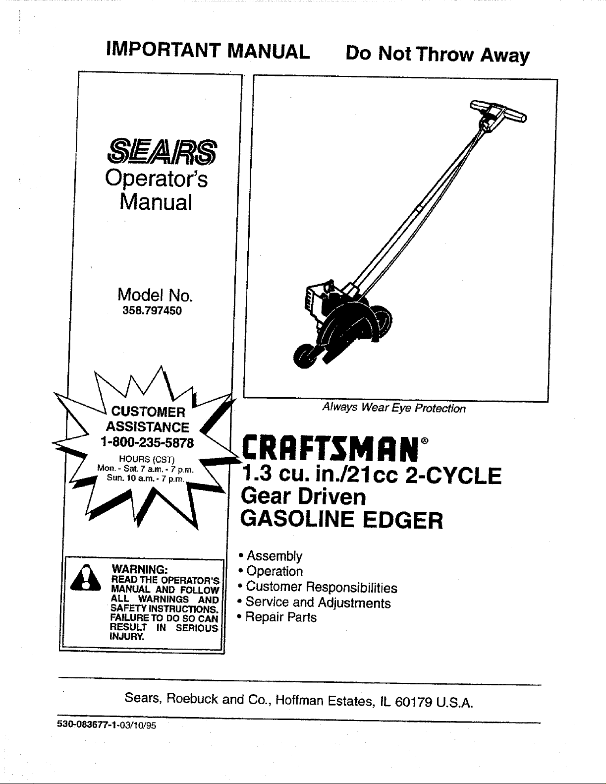
IMPORTANT MANUAL Do Not Throw Away
S _A/RS
Operator's
Manual
Model No.
358.797450
CUSTOMER
ASSISTANCE
1-800-235-5878
WARNING:
READ THE OPERATOR'S
MANUAL AND FOLLOW
ALL WARNINGS AND
SAFETY INSTRUCTIONS.
FAILURE TO DO SO CAN
RESULT IN SERIOUS
INJURY. i
Always Wear Eye Protection
FTSMRN°
1.3 cu. in./21cc 2-CYCLE
Gear Driven
GASOLINE EDGER
• Assembly
• Operation
• Customer Responsibilities
• Service and Adjustments
• Repair Parts
Sears, Roebuck and Co., Hoffman Estates, IL 60179 U.S.A.
5._'_36_-1-o311o/gs
SAFETY RULES
ALWAYS DISCONNECT SPARK PLUG WIRE AND PLACE WIRE WHERE IT CANNOT CONTACT
WARNING:
SPARK PLUG TO PREVENT ACCIDENTAL STARTING WHEN SETTING UP,TRANSPORTING,
ADJUSTING OR MAKING REPAIRS EXCEPT CARBURETOR ADJUSTMENTS.
OPERATOR SAFETY
• Always wear eye protection when operating, servic-
ing, or performing maintenance on your unit. See
"Accessories."
• Always wear heavy, long pants, long sleeves, boots,
and gloves. Do not go barefoot or wear short pants,
sort sleeves, or sandals. Loose clothing, jewelry, or
clothing with looselyhanging straps, ties, tassels, etc.,
can be caught in moving parts. Secure hair so it is
above shoulder length. Being fully covered will help
protect you from pieces of toxic plants such as poison
ivythrown by the blade, which could be more of a haz-
ard than touching the plant itself.
• Do notoperate unitwhen you are tired, ill,or under the
influenceof alcohol, drugs, or medication.
• Wear hearing protection when using this unit.
• Never start or run the unit inside a closed room or
building. Breathing exhaust fumes can kill.
• Keep handles free of oil and fuel.
° Always use the handle.
EDGING SAFETY
- Inspect the area to be edged before each use.
Remove objects (rocks, broken glass, nails, wire,
string, etc.) which can be thrown by the blade or can
wrap around the shaft.
• Keep others including children, animals, bystanders,
and helpers at least 50 feet (15 meters) away.Stop the
unit immediately if you are approached.
• Hold the unit firmly with both hands.
• Keep firm footing and balance. Do not over-reach.
• Always keep the wheels in contact with the ground.
• Keep all parts of your body away from the blade and
muffler.
• Always push the unit slowly over the ground. Stay alert
for uneven sidewalks, holes in the terrain, large roots,
etc.
• Use onlyfor jobsexplained in this manual.
UNIT MAINTENANCE SAFETY
• Inspectentire unitbefore each use. Replacedamaged
parts. Check for fuel leaks. Make sure all fasteners are
in place and securely fastened.
• Maintain the unit according to recommended proce-
dures.
• Throw away blades that are bent, warped, cracked,
broken, or damaged in any other way+Replace parts
that are cracked, chipped, or damaged before using
the unit.
° Use onlySEARS replacement blades.Never use wire,
rope, string etc.
• Use only recommended SEARS parts and acces-
sories.
• Disconnect the spark plug before performingmainte-
nance (except for carburetor adjustments).
• Remove the blade before making carburetor adjust-
ments. Hold the unit by hand. Do not make carburetor
adjustments from the blade side of the unit.
• Keep others away when making carburetor adjust-
ments.
• Never start the unit with the gear box removed. The
clutch can fly off and cause serious injury.
° Have all maintenance and service not explained in
this manual performed by your Sears Service Center.
FUEL SAFETY
° Mix and pour fuel outdoors and where there are no
sparks or flames.
• Use a container approved for fuel.
* Do not smoke or allow smoking near fuel orthe unit or
while using the unit.
• Wipe up all fuel spills before starting unit.
* Move at least 10 feet (3 meters) away from fueling site
before starting unit.
• Stop engine and allow unit to cool before removing the
fuel cap.
TRANSPORTING AND STORAGE
• Stop the unit before leaving the workarea.
•Ailow the unit to cool, run fue! out ofthe fuel tank, and
secure the unit before storing or transporting it in a
vehicle.
* Before storing the unit, use up fuel left in the carbure-
tor by starting the unit and letting it run until it stops.
Always allow the unit to coo! before storage+
• Store unit and fuel in an area where fuel vapors can-
not reach sparks or open flames from water heaters,
electric motors or switches, furnaces, etc.
* Store unit so the blade cannot accidentally cause
injury.
• Store unit out of reach of children.
I Exposure to vibrationsthrough prolonged use of gasoline powered hand toolscould cause blood vessel or nerve damage in the l
Ifingers, hand, and joints of people prone to circulationdisordersor abnormal swellings. Prolongeduse in cold weather has been I
Ilinked to blood vesseldamage in otherwise healthypeople, tfsymptoms occursuch as numbness, pain, lossof strength,change !
tin skin color or texture, or loss of feeling in the fingers, hands or joints, discontinue the use of this tool and seek medical atten-}
Ition. An anti-vibration system does not guarantee the avoidanceof these problems.Users who operate powertoolson a cent!n- I
lual and reguiar basis must monitor closely their physicalconditionand the condition of this unit. I
_C_ LOOK FOR THIS SYMBOL TO POINT OUT IMPORTANT SAFETY PRECAUTIONS. 1
IT MEANS - ATTENTION!.t! BECOME ALERT!!! YOUR SAFETY IS INVOLVED.
SAFETY NOTICE
-2-
t
SAFETY RULES
DANGER
THIS POWER TOOL CAN BE DANGEROUS! THIS UNIT CAN CAUSE SERIOUS INJURY INCLUD-
ING AMPUTATION OR BLINDNESS TO THE OPERATOR AND OTHERS. THE WARNINGS AND
SAFETY INSTRUCTIONS IN THIS MANUAL MUST BE FOLLOWED TO PROVIDE REASONABLE
SAFETY AND EFFICIENCY IN USING THIS UNIT. THE OPERATOR IS RESPONSIBLE FOR FOL-
LOWING THE WARNINGS AND iNSTRUCTIONS IN THIS MANUAL AND ON THE UNIT. READ THE
ENTIRE OPERATOR'S MANUAL BEFORE ASSEMBLING AND USING THIS UNIT! RESTRICT THE
USE OF THIS POWER UNIT TOPERSONS WHO READ, UNDERSTAND, AND FOLLOW THE WARN-
INGS AND INSTRUCTIONS IN THIS MANUAL AND ON THE UNIT. NEVER ALLOW CHILDREN TO
USE THIS UNIT.
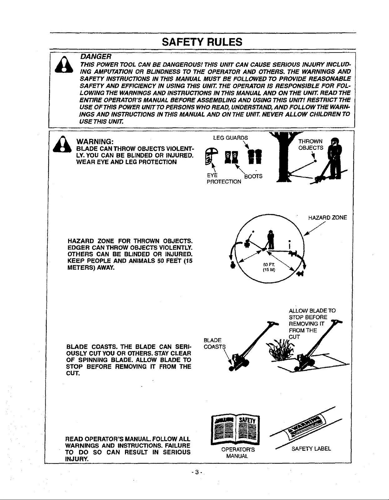
WARNING:
BLADE CAN THROW OBJECTS VIOLENT-
LY.YOU CAN BE BLINDED OR INJURED.
WEAR EYE AND LEG PROTECTION
HAZARD ZONE FOR THROWN OBJECTS.
EDGER CAN THROW OBJECTS VIOLENTLY.
OTHERS CAN BE BLINDED OR INJURED.
KEEP PEOPLE AND ANIMALS 50 FEET (15
METERS) AWAY.
LEG GUARDS '__TH ROV'¢N
HAZARDZONE
J
ALLOW BLADE TO
STOP BEFORE
BLADE COASTS. THE BLADE CAN SERI-
OUSLY CUT YOU OR OTHERS.STAY CLEAR
OF SPINNING BLADE. ALLOW BLADE TO
STOP BEFORE REMOVING IT FROM THE
CUT.
READ OPERATOR'S MANUAL FOLLOW ALL
WARNINGS AND INSTRUCTIONS. FAILURE
TO DO SO CAN RESULT IN SERIOUS
INJURY.
FROM THE
BLADE CUT
COAST_
__ REMOVING IT
OPERATOR'S
MANUAL
-3-
CONGRATULATIONSon yourpurchaseof a Sears
CraftsmanGasolineEdger.Ithasbeendesigned,engi-
neeredandmanufacturedtogiveyouthebestpossible
dependabilityandperformance.
Shouldyouexperienceanyproblemsyoucannoteasily
remedy,pleasecontactyournearestSearsService
Center/Department.Searshascompetent,welltrained
techniciansand the proper tools to service or repair this
unit.
Please read and retain this manual.The instructionswill
enable you to assembleand maintain your unit properly.
Always observe the "SAFETYRULES."
r
MODEL NUMBER: 358.797450
DATE CODE/SERIAL NO.
DATE OF PURCHASE:
THE MODEL AND SERIALNUMBER WILL BE FOUND
ON THE PRODUCT
YOUSHOULD RECORDBOTH SERIAL NUMBER AND
DATE OF PURCHASE AND KEEP IN A SAFE PLACE
FOR FUTURE REFERENCE.
MAINTENANCE AGREEMENT
ASears Maintenance Agreement is availableon this prod-
uct.Contact your nearest Sears Store for details.
CUSTOMER RESPONSIBILITIES
• Read and observe thesafety rules.
• Follow a reguiar schedulein maintaining, caring for, and
using your unit.
• Follow the instructions under "Customer
Responsibilities" and "Storage" sections of this
Operator's Manual.
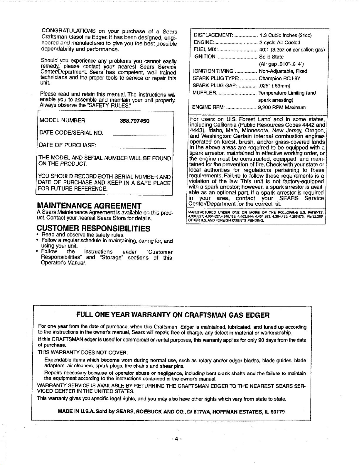
DISPLACEMENT: ................. t.3 Cubic Inches (21cc)
ENGINE: ................................ 2-cycle Air Cooled
FUEL MiX: ............................. 40:1 (3.2oz oil per gallon gas)
IGNITION: ............................. Solid State
(Air gap .010"-.014")
IGNITION TIMING: ................ Non-Adjustable, Fixed
SPARK PLUG TYPE: ............ Champion RCJ-SY
SPARK PLUG GAP: ............... 025" (.63ram)
MUFFLER: ............................ Temperature Limiting (and
spark arresting)
ENGINE RPM: ...................... 9,200 RPM Maximum
For users on U.S. Forest Land and in some states
including California (Public Resources Codes 4442 and
4443), Idaho, Main, Minnesota, New Jersey, Oregon,
and Washington: Certain internat combustion engines
operated on forest, brush, and/or grass-covered lands
in the above areas are required to be equipped with a
spark arrestor, maintained in effective working order, or
the engine must be constructed, equipped, and main-
tained for the prevention of fire. Check with yourstate or
local authorities for regulations pertaining to these
requirements. Failure to follow these requirements is a
violation of the law. This unit is not factory-equipped
with a spark arrestor; however, aspark arrestor is avail-
able as an optional part. If a spark arrestor is required
in your area, contact your SEARS Service
Center/Department for the correct kit.
MANUFACTURED UNDER ONE OR MORE OF THE FOLLOWING U.S. PATENTS:
4,904,827: 4.904,827;4,846,123: 4,463,544; 4.451.983; 4.364,435; 4.2B_,675; Re,32,266
OTHER U.S.AND FOREIGN PATENTS PENDING.
FULL ONE YEAR WARRANTY ON CRAFTSMAN GAS EDGER
For one year from the date of purchase, when this Craftsman Edger is maintained, lubricated, and tuned up according
to the instructions in the owner's manual, Sears will repair, free of charge, any defect in material or workmanship.
If thisCRAFTSMAN edger isused for commercial or rentalpurposes, this warranty appliesfor only 90 days from the date
of purchase.
THIS WARRANTY DOES NOT COVER:
Expandable items which become worn during normal use, such as rotary and/or edger blades, blade guides, blade
adapters, air cleaners, spark plugs, tire chains and shear pins.
Repairs necessary because of operator abuse or negligence, includingbent crank shafts and the failure to maintain
the equipment accordingto the instructionscontained in the owner'smanual.
WARRANTY SERVICE tS AVAILABLE BY RETURNING THE CRAFTSMAN EDGER TO THE NEAREST SEARS SER-
VICED CENTER IN THE UNITED STATES.
This warranty gives youspecific legal fights, and you may also have other rightswhich vary from state to state.
MADE IN U.S.A. Sold by SEARS, ROEBUCK AND CO., DI 8t7WA, HOFFMAN ESTATES, IL 60179
-4-
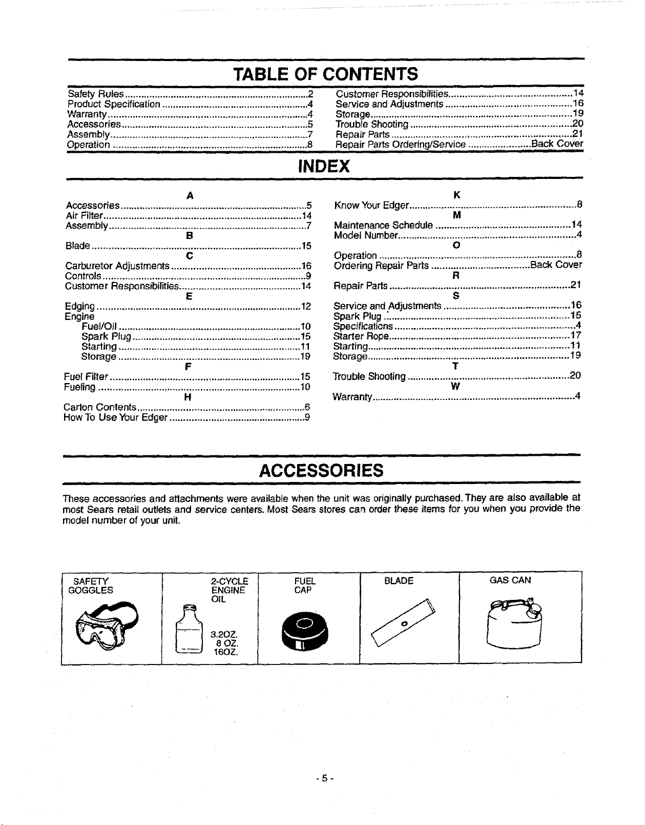
TABLE OF CONTENTS
Safety Rules ................................ ,......,, ................... i__.2 Customer Responsibilities ............................................. 14
Product Specification ...................................................... 4 Service and Adjustments .............................................. 16
Warranty .......................................................................... 4 Storage .......................................................................... 19
Accessories ..................................................................... 5 Trouble Shooting ........................................................... 20
Assembty......................................................................... 7 Repair Parts.................................................................. 21
Operation. ...................... :.;::::,. .......... ;""1..:.':.;":" .............8 .....Repair Parts Order!ng/Service .......... ......... Back Cover
.. iiiiiii iiiiiiiiiii1[ iiiii i iiiiiiiiiiiiiii i i iii iiiiiiiii iiiiii iiiiiiii iii
INDEX
,,, ,,,,,,,, .................................................. ,,,,,,,, , HIII I
A
Accessories..................................................................... 5
Air Filter ......................................................................... t4
Assembly ......................................................................... 7
B
Blade ............................................................ ................. 15
C
Carburetor Adjustments ................................................ 16
Controls ........................................................................... 9
Customer Responsibilities ............................................. 14
E
Edging ........................................................................... 12
Engine
FueVOtl ................................................................... 10
Spark Plug .............................................................. 15
Starting ................................................................... tl
Storage ................................................................... 19
F
Fuel Filter ...................................................................... 15
Fueling .......................................................................... 10
H
Canon Contents .............................................................. 6
HowTo Use Your Edger .................................................. 9
Know Your Edger ............................................................. 8
Maintenance Schedule ................................................. 14
Model Number................................................................. 4
Operation ........................................................................ 8
Ordering Repair Parts .................................... Back Cover
Repair Paris .................................................................. 21
Service and Adjustments .............................................. 16
Spark Plug ..'.................................................................. 15
Specifications .................................................................. 4
Starter Rope.................................................................. 17
Starting .......................................................................... 11
Storage .......................................................................... 19
Trouble Shooting ........................................................... 20
Warranty .......................................................................... 4
K
M
O
R
S
T
W
..................................... , ,,,,,,,,,,,,i
ACCESSORIES
....,,, i,ii i IIHI , ...... ,[]
These accessories and attachments were available when the unit was originally purchased. They are also available at
most Sears retail outlets and service centers. Most Sears stores can order these items for you when you provide the
model number of your unit.
SAFETY'
GOGGLES
2-CYCLE
ENGINE
OIL
3.2OZ,
8 OZ.
16OZ.
FUEL
CAP
BLADE
GAS CAN
-5-
H.=.H= ..=..H= = ,,,,,,,,,,,,,,,,,,,,,,,,,,,,= .H.... =HIH= """=
CARTON CONTENTS
iiiiiiiiiilu iiiiiiiui i ii IIIIIIIIIIIIJJlIIIHI I i i i II i ii iii
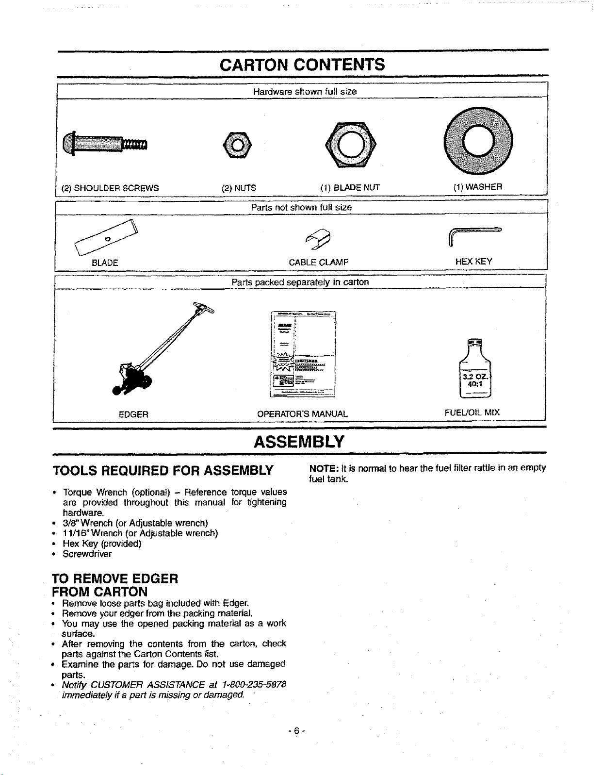
Hardware shown full size
(2) SHOULDER SCREWS (2) NUTS (1) BLADE NUT (t) WASHER
Parts not shown full size
BLADE CABLECLAMP HEXKEY
Parts packed separately in carton
EDGER
iiiii iii ii
OPERATOR'SMANUAL
i = i
ASSEMBLY
TOOLS REQUIRED FOR ASSEMBLY
• Torque Wrench (optional) - Reference torque values
are provided throughout this manual for tightening
hardware.
• 3/8"Wrench (or Adjustable wrench)
• 11/16"Wrench (or Adjustable wrench)
• Hex Key (provided)
• Screwdriver
TO REMOVE EDGER
FROM CARTON
• Remove looseparts bag includedwith Edger
• Remove youredger from the packing material.
• You may use the opened packing material as a work
surface.
• After removing the contents from the carton, check
parts against the Carton Contents list,
• Examine the parts for damage, Do not use damaged
parts.
• Notify CUSTOMER ASSISTANCE at 1_800-235-5878
immediately if a part is missing or damaged.
---!_ ,! p-_
• I
I
FUEL]OILMIX
iiiii ii iiii iiii
NOTE: It isnormal to hear the fuel filter rattle in an empty
fuel tank.
-6-
_1_ ANGER:
DO NOT START THE ENGINE WITHOUT
THE GUARD AND BLADE COMPLETELY
ASSEMBLED. OTHERWISE, THE CLUTCH
CAN COME OFF AND SERIOUS INJURY
CAN RESULT.
ALWAYS WEAR GLOVES WHEN HAN-
DLINGTHE BLADE. THE BLADE CAN BE
SHARP ENOUGH TO CUT YOU EVEN
THOUGHITISTOO DULLTO CUTWOOD.
IF UNIT IS RECEIVED ASSEMBLED,
REVIEW ALL STEPS IN THIS SECTION TO
BE SURE ASSEMBLY IS CORRECT AND IS
ADJUSTED FOR THE OPERATOR.
HOW TO ASSEMBLE YOUR EDGER
ASSEMBLY
J
Figure2
BLADE ASSEMBLY (Fig, 3)
WARNING:
WEAR PROTECTIVE GLOVES WHEN
HANDLING OR PERFORMING MAINTE-
NANCE ON THE BLADE TO AVOID
INJURY.
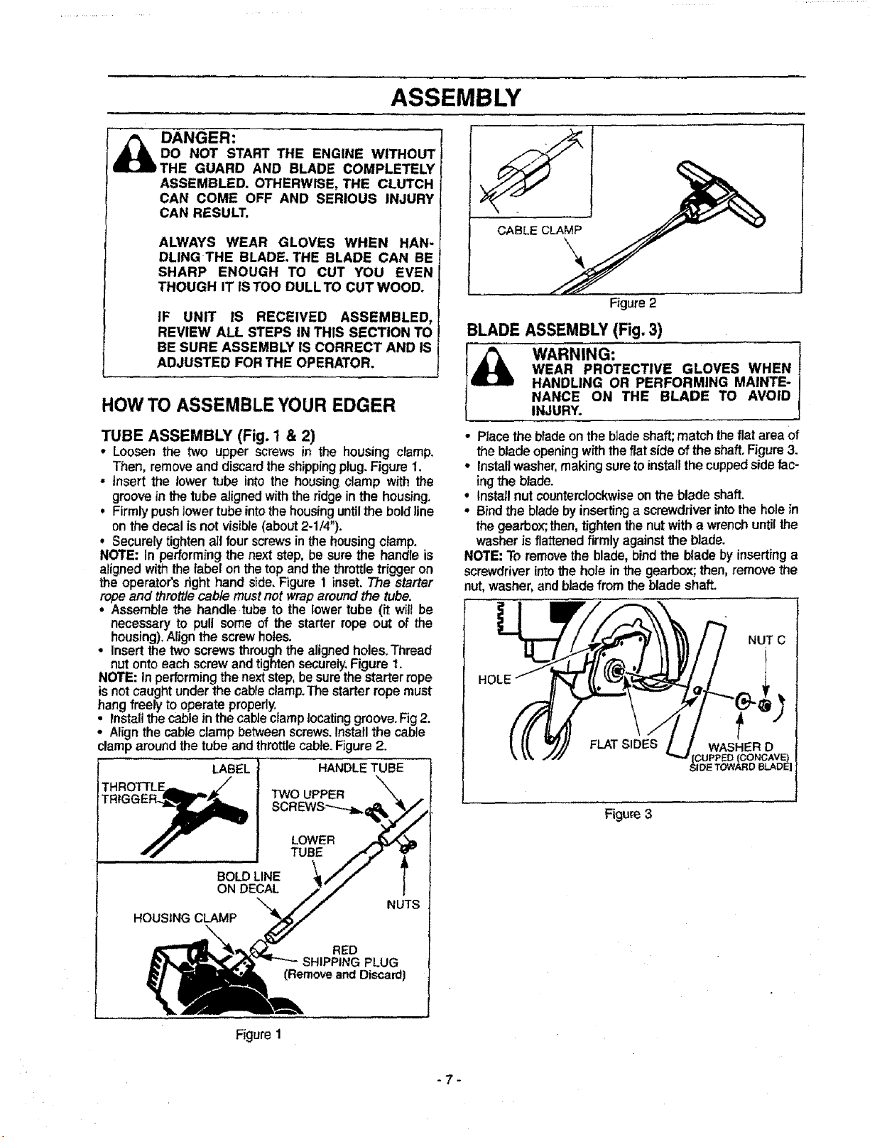
TUBE ASSEMBLY (Fig. 1 & 2)
• Loosen the two upper screws in the housing clamp.
Then, remove and discard the shippingplug. Figure 1.
• Insert the lower tube into the housing,clamp with the
groove inthe tube aligned with the ridgeinthe housing.
° Firmly push lowertube intothe housing until the bold line
on the decal is not visible (about 2-1/4").
° Securely tightenall four screws in the housingclamp.
NOTE: In performing the next step, be sure the handle is
alignedwiththe label on thetop and the throttletriggeron
the operator'srighthand side. Figure 1 inset.The starter
rope and throttle cable mustnotwrap around the tube.
• Assemblethe handle tube to the lowertube (it wilt be
necessary to pull some of the starter rope out of the
housing).Alignthe screwholes.
• Insertthe two screwsthrough the alignedholesoThread
nutontoeach screw andtightensecurely.Figure 1.
NOTE: In performingthe nextstep,be surethestarter rope
isnotcaught underthe cableclamp.Thestarterrope must
hangfreelyto operateproperly.
install the cableinthe cable ciamplocating groove. Fig2.
• Alignthe cable clamp between screws.Installthe cable
clamparound the tube and throttlecab_e.Figure2.
LABEL HANDLE TUBE
THROTTLE,m,,._ = _"
TRtGG_ TWOTUBELOWERUPPER
• Placethe blade onthe blade shaft; match theflat area of
the blade opening with theflat side of the shaft, Figure 3.
• Installwasher,making sure to installthe cupped side fac-
ing • e blade.
• Install nut counterclockwise on the blade shaft.
• Bindthe bladeby inserting a screwdriver into the hole in
the gearbox; then, tighten the nut witha wrench until the
washer isflattened firmly against the blade.
NOTE: To removethe blade, bind the blade by inserting a
screwdriver intothe hole inthe gearbox; then, remove the
nut, washer,andblade from the blade shaft.
NUT C
FLAT SIDES
Figure 3
BOLD LINE
ON DECAL
HOUSING CLAMP
NUTS
RED
SHIPPING PLUG
(Remove and Discard]
Figure 1
-7-
OPERATION
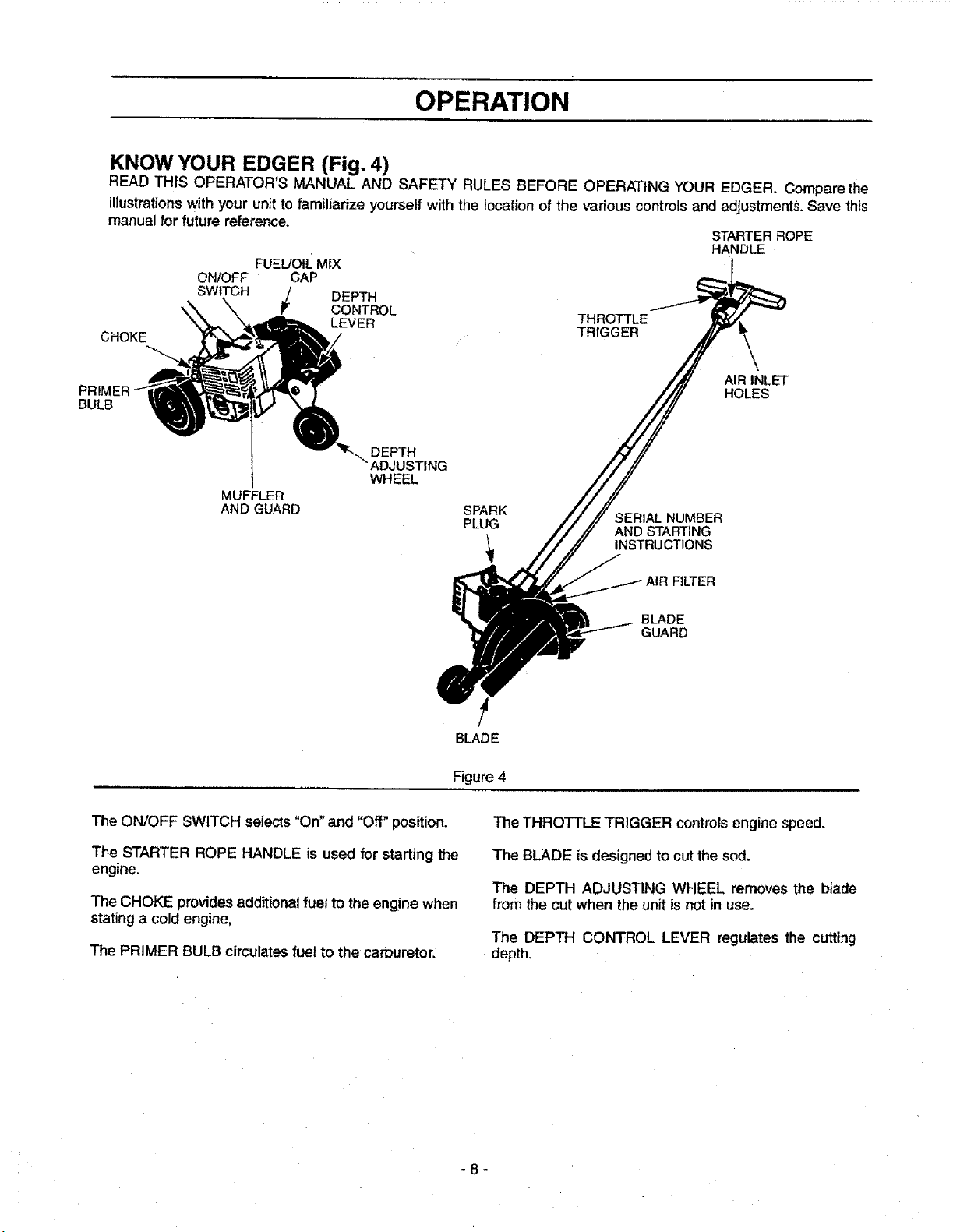
KNOWYOUR EDGER (Fig. 4)
READ THIS OPERATOR'S MANUAL AND SAFETY RULES BEFORE OPERATING YOUR EDGER. Compare the
illustrationswith your unit tofamiliarize yourselfwith the locationof the variouscontrols and adjustmentS.Save this
manual for future reference.
STARTERROPE
ON/OFF CAP
FUEL/OILMIX
HANDLE
CHOKE
PRIMER
BULB
SWITCH _ DEPTH
CONTROL
LEVER
MUFFLER
AND GUARD
DEPTH
WHEEL
SPARK
PLUG
BLADE
THROTTLE
TRIGGER
AIR INLET
HOLES
SERIAL NUMBER
AND STARTING
INSTRUCTIONS
FILTER
BLADE
GUARD
The ON/OFF SWITCH selects"On" and "Off" position.
The STARTER ROPE HANDLE is used for starting the
engine.
The CHOKE provides additionalfuel to the engine when
stating a cold engine,
The PRIMER BULB cimulates fuel to the carburetor.
Figure4
The THROTTLE TRIGGER controlsengine speed.
The BLADE isdesigned tocut the sod.
The DEPTH ADJUSTING WHEEL removes the blade
from the cut when the unit isnot in use.
The DEPTH CONTROL LEVER regulates the cutting
depth.
-8-
OPERATION
HOW TO USE YOUR EDGER
STOPPING YOUR ENGINE
• Move on/off switch to the "Off" position.
• If engine does notstop, move choke lever to fult choke
position.
CONTROLS (Fig. 5 & 6)
THROTTLE TRIGGER
• The throttle tdgger allows for variable contmt of
engine speed.
, The throttle trigger is actuated by the indexfinger on
your right hand.
CHOKE
• The choke is set by rotating the choke lever fully for
cold or refueted engine starts.
PRIMER BULB
• The primer bulb is used to circulatefuel to the carbu-
retor.
• The primer bulb is activated by pressingon itwith
yourthumb.
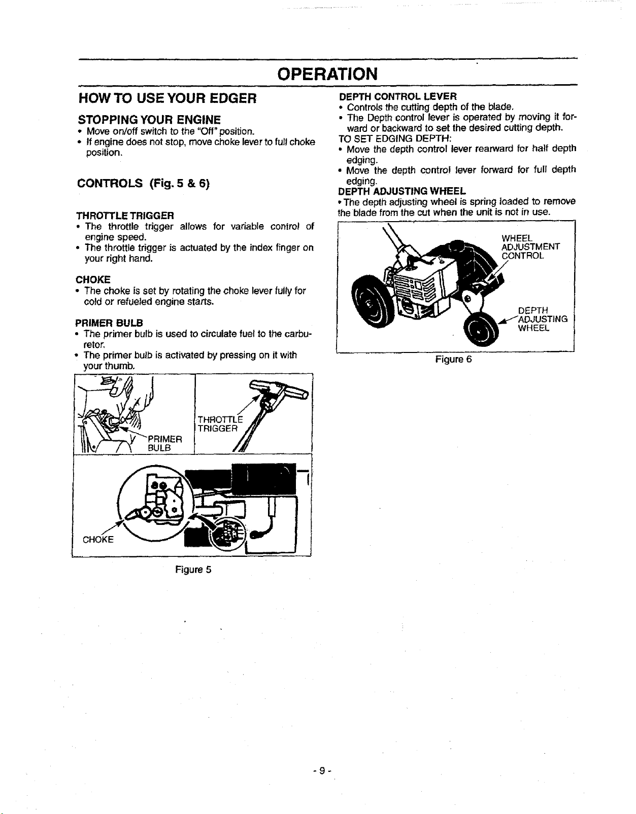
DEPTH CONTROL LEVER
• Controlsthecutting depth of the blade.
• The Depthcontrol lever is operated by moving itfor-
ward or backwardto set the desired cuttingdepth.
TO SET EDGING DEPTH:
° Move the depth control lever rearward for half depth
edging.
• Move the depth control lever forward for full depth
edging.
DEPTH ADJUSTING WHEEL
°The depth adjusting wheel is springloaded to remove
the blade from the cut when the unitis not in use.
WHEEL
ADJUSTMENT
CONTROL
DEPTH
WHEEL
Figure 6
CHOKE
BULB
Figure 5
-9-
 Loading...