

Craftsman 358797121 Owner’s Manual

IMPORTANT MANUAL
Operator's
Manual
Do Not Throw Awa_
i i i iHi .ll...,.
MODEL NO.
358.797121-26cc
(16" Cutting Par
A WARNING:
Read theOperator'sManual
md Follow All Warnings
and Safety Instructions.
_ure ToDo So Can Result
in Serious I_iury.
Always Wear Eye Protection During Operation
26€€ GAS WEEDWACKER _
2 Cycle Engine
®Assembly
o Operation
Fuel Mix 40:1
o Maintenance
• Repair Parts
Sold by Sears, Roebuck and Coo, Chicago, Iti. 60684 U.S.A.
.................... N,
530-067909-4-07112/91 ©Sears, Roebuck and Co, 1991

ONE YEAR LIMITED WARRANIY ON CRAlrl'SMAN WEEKWACKER ®
For One Year from dale of archase when this Weedwacke¢ _ is maintained lubricated and tuned up according to the operating
and maintenance instructionPs in the operators manual Sears will repair free of charge any defect in rnateria] or workmanship
This wammly excludes nylon line spark plug and a r c eaner" wb ch are expendable paris and become worn during nomlal use ._
WARRANTY SERVICE IS AVAILABLE BY CONIACTING IHE NEARESI" SEARS SERVICE CENIER/DEPARIMENI
IN THE UNIFED STALES 7his warranty applies only while this product is in ase in the United States
'This '_trvant)' gives you specific legal rights and you may also have other rights which vary from state to stale _.
SEARS, ROEBUCK AND CO, DEPT D/731CR-W, SEARS rOWER CHICAGO, IL 60684 .,_
TABLE OF CONTENTS
WARNINGS AND SAFETY INSTRUCTIONS
KNOW YOUR TRIMMER
ASSEMBLY ..
ACCESSORIF_ .....
ENGINE INFORMATION
A Fueling YourEngine
B. Pre-Operation Checks
C Starting Instructions
D Operating Instructions
USING YOUR TRIMMER
A Irimmer Safety
B Trimmer Line Advance
C Cutting Methods
D Line Replacement
3 GENERAL MAINTENANCE ................ 17
6 A Maintenance Safety .................... 17
7 B_ Air Filter.................... 17
I0 C. StarterRope ............................ 18
11 D Flexible Drive Shaft Lubrication .............. 19
11 E Carburetor Adjustments ................ 20
12 F. Storage ............................. 22
12 G, Trouble Shooting Chart ....................... 22
13 REPAIR PAR'IS LIST ......................... 23
13 INDEX ........................................ 26
14 QUICK REFERENCE PAGE ..................... 27
14
15
16
SPEC F| ATION
"ENGINE' 'TTPE:
i DISP,LACEMENT! ...........
ENGINE R_M:
2-Cycte, Air-Cooled
26cc
Operating ' 7500
Idle -- 2800 - 3200
I NmON:................
CARBURETOR:
SoiidS te
Diaphragm All Positions with
adjustable fue! mixture jets
ENGINE "OFF":
STARTER:
MUFFLER:
Positive Switch
Auto Rewind
2bmpemture Limiting (not
spark arresting; see note p,5)
CLUTCH:
FUEL TANK:
SPARK pLUG:
SPARK,,PLUG GAP:
MODULE AIR GAP:
17 tL 0Z, '.................
71-85854 <€i_i4)
.025"
.010"/ .0t4"
LUBRICATION:
(See "Fueling Your'Engine")
CUTIING LINE:
DS0" Diameter Sears Laser
Line®
"SHAFT LEN_: 48"
NOTE: LASER LINE ® tS A REGISTERED TRADEMARK OF
WHITE CONSOLIDATED INDUSTRIES, INC
M'ANUFACI_UREDUNDERONE OR MORE OF tHE FOLLOWINGU.S
PATENTS:3 708,967;3 826 068;3_859,776;4_035,912;4,052_789:4,054,992;
4_067,108:4, t04,797;4.114=269;4_1245)38;4,156_31214,156,967;4_161,820;
4,167,8|2; 4_269;372;4,286,675;4_107,901;4. t t2,653; 4_136o446;4,168,572;
4,183,138;4,189.833;4,21t,004;4°211_005;4.236,311:4_236_312;4,290,200;
4.362,ff/4;4_366,622;4_382,356;4,451,983;4,483,069;4.798,185;4,819.742;
4,823,465; 4,825_548; 4,835,867; 4,841.929; 4.846,123; 4852.258;
DES 249.630 U S AND FOREIGNPATENIS PENDING
IGNITION SWITCH
SHIELD
"_'_MUFFLI_ I'RIMbtF_ HE.M)
B_--"e _"_ SPARK PLUG
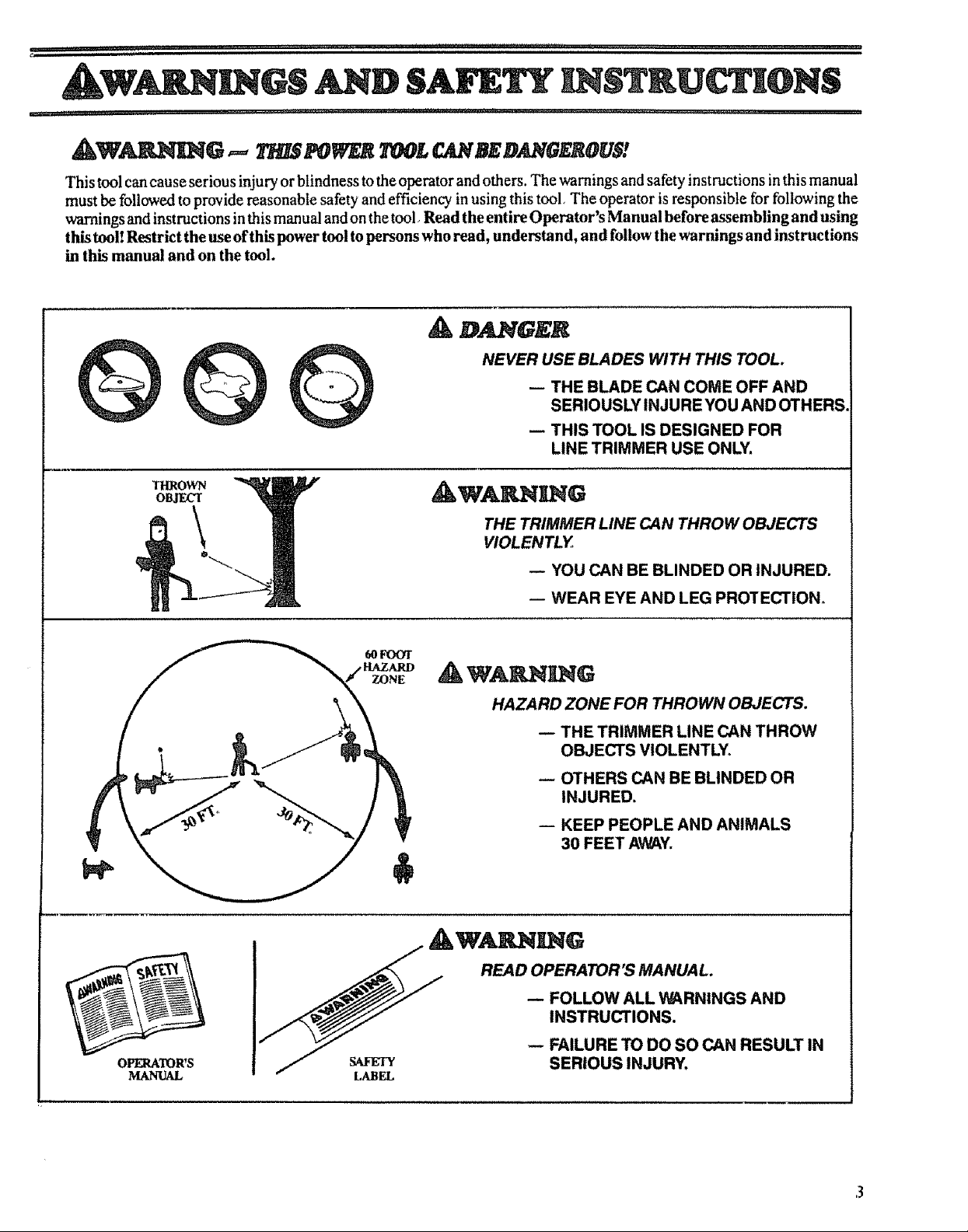
This tool can cause serious injury or blindness to the operator and others. The warnings and safety instructions in this manual
must be followed to provide reasonable safety and efficiency in using this tool, The operator is responsible for following the
warnings and instructions in this manual and on the tool Read the entire Operator's Manual before assembling and using
this tool! Restrict the use of this power tool to persons who read, understand, and follow the warnings and instructions
in this manual and on the tool.
A D GEK
NEVER USE BLADES WITH THIS TOOL.
-- THE BLADE CAN COME OFF AND
SERIOUSLY INJURE YOU AND OTHERS.
-- THIS TOOL IS DESIGNED FOR
LINE TRIMMER USE ONLY.
AW&I IG
THE TRIMMER LINE CAN THROW OBJECTS
VIOLENTLY
YOU CAN BE BLINDED OR INJURED.
-- WEAR EYE AND LEG PROTECTION.
OPERATOR'S
MANUAL
HAZARD ZONE FOR THROWN OBJECTS.
-- THE TRIMMER LINE CAN THROW
OBJECTS VIOLENTLY°
-- OTHERS CAN BE BLINDED OR
INJURED.
-- KEEP PEOPLE AND ANIMALS
3O FEET AWAY.
READ OPERATOR'S MANUAL.
-- FOLLOW ALL WARNINGS AND
INSTRUCTIONS.

........................ i,i ..... i
WARNINGS AND SALTY IIgSTN,
i i,i ,111ii1,1 ,,i,iiiii1,1,,,,,,,i , , i ........ r
A OPERATOR SAFETY
1 Always wear a safety face shield or safety goggles. See
"Accessories"
2 Keep hair, fingeIs, and all othet parts of the body away
h'om openings and moving parts Always wear heavy,
long pants,,boots, and gloves Do not go barefbot or wear
sandals, jewelry, short pants, loose clothing, or cloth-
ing with loosely hanging straps, ties. tassels, etc, Secure
hair so it is above shoulder length Being fully covered
will help protect you from pieces of toxic p)ants (such
as poison ivy) thrown by the Trinmaer Head, which
could be more of a hazard than touching the plant itself
3. Do not operate this toolwhen youare tired, ill, or under the
influence of alcohol, drugs, or medication.
4. Always use the assist handle. See "Assembly,"
5. Wear hearing protection if you use this tool for more than
!V2hours per day.
6. Never startor run the engine insidea closed room orbuild-
ing Breathing exhaust fumes can kilt
7. Keep handles fi'ee of oil and fuel.
& TOOLSAFETY
1. Inspectentiretoolbeforeeachuse. Replacedamagedparts.
Check for fuel leaksand make sure all fasteners are in place
and securely fastened
2 Replace trimmer head parts that a_e cracked, chipped,
broken, or damaged inany other waybefore using the tool_
3 Use only 080" diameter Sears Laser Line Never use
wi_e. rope. string, etc
4 Be sure the shield is properly attached.
5. Useonly the specifiedtrimmer head See "Specifications."
Make sure the trimmer head is properly installed and
fastened. Refer to "Assembly"
6 Besure the trimmer head stops turning when engine idtes_
See "Carburetor Adjustments."
7. Make carburetor adjustrnents with the drive shaft housing
supported to prevent the trimmer line from contacting any
object Hold the tool by hand; do not use the optional
shoulder strap for support
8 Keep others awaywhen making carburetor adjustments..
9. Use only accessories or attachments as recommended for
this tool by Sears
FUEL SAt Ir"I "
A
1_ Move at least 10(Letaway from fueling site betbre start_
ing engine.
2. Use a container approved for fuel..
3 Do not smoke or allow smoking near fuel or the tool or
while using the tool
4. Wipe up all fuel spills before starting engine.
5 Stop engine before removing fuel cap, Allow the engine
to cool before refueling.
6. Run fuet out of the rue! system before storing the tool
2 Store tooland fuelinanarea where fuel vapors cannot reach
sparks or open flames from water heaters, electric motors
or switches, furnaces, etc
CD' t'/NG r
1. Inspect the area to be cut before each use Remove objects
(rocks, broken glass, nails, wire, string, etc )which can be
thrown or become entangled inthe trimmer head_
2. Keep others including children, animals, bystanders, and
helper'soutside the 60 tbot Hazard Zone Stop the engine
immediately i[ you are approached.
3. Always keep the engine on the right side of your body,
4 Hold the tool firmly with both hands
5. Do not overreachor use from unstable surfaces such as
ladders, trees, steep slopes, rooftops, etc, Use extra care
when cleaning on stairways Keep firnafooting and b',dance
atall times
6 Keep trimmer head below waist level
7 Do not raisethe engine aboveyour waist The trirrmaerhead
can come dangerously elose to your body.
8 Keepalt parts ofyourbody awayfrom thetrimmer head and
muffler when the engine is running
9 Useonly forjobs explained in this manual.
A MAINTENANCESAFETY
1_Maintain the toot according to reco_ranended procedures.
Keep the trimmer line at the proper length.
2 Never start the engine with the clutch shroud removed The
clutch can fly apart and cause serious injury
3 Disconnect the spark plug before performing maintenance
except for carburetor adjustments.
4. Make carburetor adjustments with the drive shaft housing
suppoaed to prevent the trimmer line from contacting any
object.. Hold the toot by hand; do not use the optional
shoulder strap for support
5 Keep others away when making carburetor adjustments
6. Use only genuine replacement parts as recommended
by Sears_
• T L4 .SPORTL G/ D STOOGE
l Hand carry the toolwith theengine stopped and themuffler
away from your body
2o Allow the engine tocool, run fuelout ofthe fuel system, and
secure the toot before transporting in a vehicle or storing
3. Before storing the tool, use up fuel left in the fuel lines and
carburetor by starting the engine and letting it run until it
stops.
4. Store tooland fuel inanarea where fuelvapors cannot reach
sparks or open flames from water heaters, electric motors
or switches, furnaces, etc.
5_ Store the tool so the line limiter cannot accidenta!ly cause
injury. The tool can be hung by the drive shaft housing or
by the bracket below the engine
6. Store tool out of reach ofchildren,
Ifsituations occur which are not covered in thismanual, use
care and good judgement. Contact your Sears Service
Center/Depa_nent ifyou need assistance.
SAFETY NOTICE
Exposure to vibrations through prolonged use of gasoline powered hand tools could cause blood vessel or nervedamage inthe fingers,
hands, and wrists ofpeople prone to circulation disorders or abnormal swellings. Prolonged use incold weather has been linked
to blood vessel damage in otherwise healthy people. If symptoms occur such as numbness, pain, loss of strength, change in skin
color or texture, or loss of feeling in the fingers, hands, or wrists, discontinue the use of this tool and seek medical attention. An
anti-vibrati onsystem does not guarantee the avoidance of these problems. Users wh ooperate power tools on acontinual and regu-
lar basis must monitor closely their physical condition and the condition of this tool.
KNOW YOUR TRIMMER
._1,11.................
A. _ODU_'ION
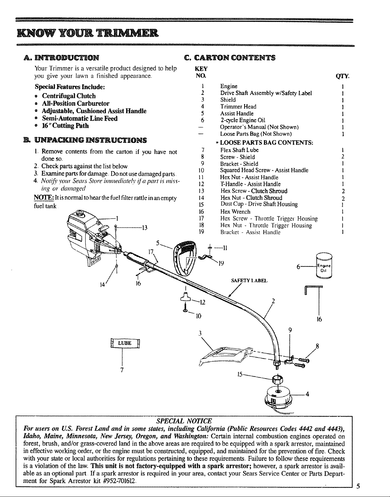
Your Tr'immer is a versatile product designed to help
you give your lawn a finished appearance.
Special Features Include:
• Centrifugal Clutch
• All-Position Carburetor
e Adjustable, Cushioned Assist Handle
• Semi-Automatic Line Feed
o 16"Cutting Path
K UNP&_G _ISTRU_ON$
L Remove contents from the canon if you have not
done so.
2. Check parts against the list below
3. Examfinepartsfordamage Donotusedamagedpans
4 Notifi/),our Sears Store immediately ija part is miss'-
ing cn damaged
NOTE: it is normal to hear the fuel fdter rattle in an empty
fue! tank
!3
C. _RTON CONTENTS
KEY
NO.
1 Engine
2 Drive Shaft Assembly w/Safety Label
3 Shield
4 Trimmer Head
5 Assist Handle
6 2-cycle Engine Oil
-- Operator's Manual (Not Shown)
-- Loose Parts Bag (Not Shown)
* LOOSE PARTS BAG CONTENTS:
7 Flex Shaft Lube
8 Screw - Shield
9 Bracket -Shield
10 Squared Head Screw - Assist Handle
i1 Hex Nut - Assist Handle
12 T-Handle - Assist Handle
13 Hex Screw - Clutch Shroud
t4 Hex Nut - Clutch Shroud
15 Dust Cup - Drive Shaft Housing
16 Hex Wrench
17 Hex Screw - Thfottle Trigge_ Housing
18 Hex Nut - Throttle Trigger Housing
19 Bracket - Assist Handle
QTY_
I
2
1
1
I
1
2
2
!
1
I
I
I
14 16
7
SPECIAL NOTICE
For users on U.S. Forest Land and in some states, including Cahfornia (Public Resources Codes 4442 and 4443),
Idaho, Maine, Minnesota, New Jersey, Oregon, and Washington: Certain internal combustion engines operated on
forest, brush, and/or grass-covered land in the above areas are required to be equipped with a spark arrestor, maintained
in effective working order, or the engine must be constructed, equipped, and maintained for the prevention of fire_ Check
with your state or local authorities for regulations pertaining to these requirements, Failure to follow these requirements
is a violation of the law. This unit is not factory-equipped with a spark arrestor; however, a spark arrestor is avail-
able as an optional part If a spark arrestor is required in your area, contact your Seres Service Center or Parts Depart-
ment for Spark Arrestor kit #952-701612_
SAFETY LABEL
...........................................,,,,,i?,?_I;,L'_I_,:_??+_;,i?,+i';L,,,;,i,:;,'',,+,+........ r.......................................................
___P' (_'too| is rece|vedas_embJed, repeat all steps in thissecthm to be sure assembly is_
and is m_ijusted for the operator.)
This Operator's Manual has been developed to help you
assemble the tool and to provide its safe operation, It is
important thai you read the entire manual to become
familiar with the tool below you begin assembly
B, AS._EMBLY S_PS
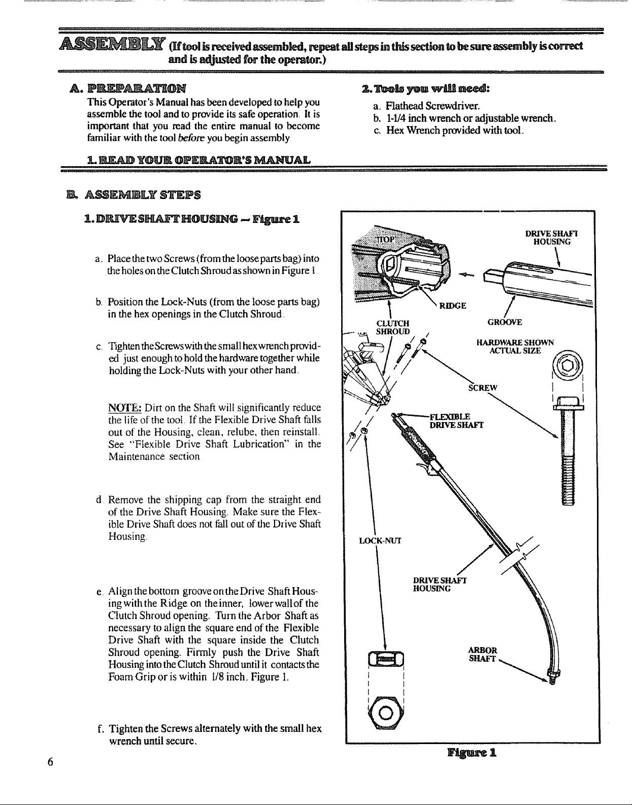
1. D[_IVE $_ HOUSING -- Figure 1
a o Place the two Screws (from the loose parts bag) into
the holes on the Clutch Shroud as shown in Figure I
b, Position the Lock-Nuts (from the loose parts bag)
in the hex openings in the Clutch Shroud,
c, Tighten theScrewswith the smatl hexwrench provid -
ed just enough to hold the hardware together while
holding the Lock-Nuts with your other hand,,
a+ Flathead Screwdriver+
b. 1-1/4inch wrench or adjustable wrench+
c, Hex Wrench provided with tool+
DRIVE SHAFI
HOUSING
' RIDGE
CLUTCH
SHROUD
GROOVE
.............3,','.......
NOTE: Dirt on the Shaft will significantly reduce
the life of the tool, Ifrthe Flexible Drive Shaft falls
out of the Housing, clean, telube, then reinstall,
See "Flexible Drive Shaft Lubrication" in the
Maintenance section
d Remove the shipping cap fl'om the straight end
of the Drive Shaft Housing, Make sure the Flex-
ible Drive Shaft does not fall out of the Drive Shaft
Housing,
e Align the bottom groove on the Drive Shaft Hous-
ingwiththe Ridge on theinner, lowerwallof the
Clutch Shroud opening, Turn the Arbor Shaft as
necessary to align the square end of the Flexible
Drive Shaft with the square inside the Clutch
Shroud opening+ Firmly push the Drive Shaft
Housing into the Clutch Shroud until it contacts the
Foam Grip or is within I/8 inch+ Figure 1.
+ I
I I
I t
f. Tighten the Screws alternately with the small hex
wrench until secure.
®
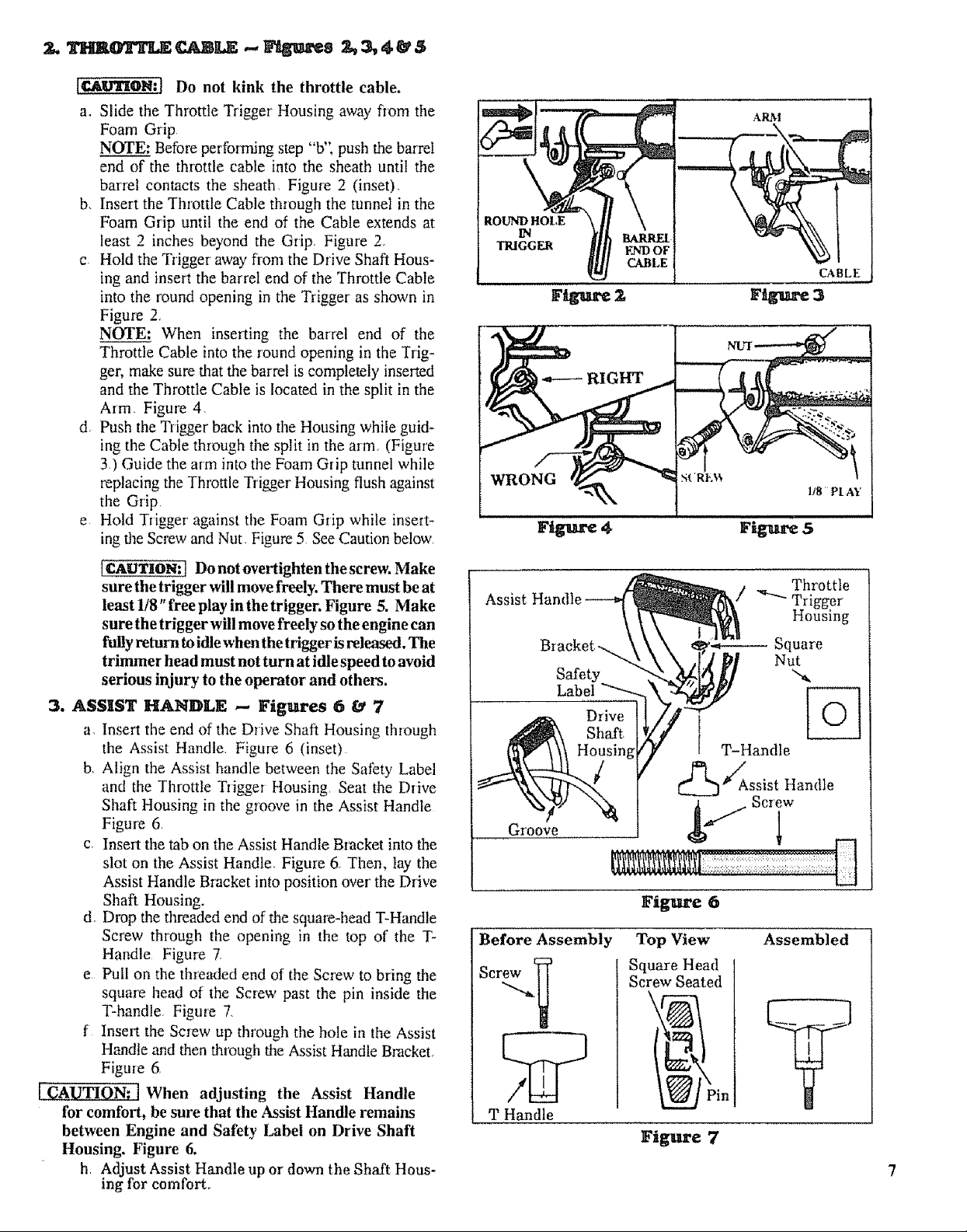
I_WI'ION:J Do not kink the throttle cable.
ao Slide the Throttle Trigger Housing away flora the
Foam Grip
NOTE: Betbre performing step "b', push the barrel
end of the throttle cable into the sheath until the
barrel contacts the sheath, Figure 2 (inset)
b, Insert the Throttle Cable through the tunnel in the
Foam Grip until the end of the Cable extends at
least 2 inches beyond the Grip, Figure 2,
c Hold the Trigger away flora the Drive Shaft Hous-
ing and insert the barrel end of the Throttle Cable
into the round opening in the Trigger as shown in
Figure 2,
NOTE: When inserting the barrel end of the
Throttle Cable into the round opening in the Trig-
ger, make sure that the barrel is completely inserted
and the Throttle Cable is located in the split in the
Aim, Figure 4,
d, Push the Triter back into the Housing while guid-
ing the Cable through the split in the arm (Figure
3,) Guide the arm into the Foam Grip tunnel while
replacing the Throttle Trigger Housing flush against
the Grip
e Hold Trigger against the Foam Grip while insert-
ing the Screw and Nut Figure 5 See Caution below
ROUND HOLE
IN
TRIGGER
Z
ICAUTION:] Do not overtighten the screw. Make
sure the trigger will move freely. There must be at
least 1/8" free play in the trigger. Figure 5. Make
sure the trigger will move freely so the engine can
fully return to idle when the trigger isreleased. The
trimmer head must not turn at idle speed to avoid
serious injury to the operator and others.
3. ASSIST HAN]r)LE ,-- Figures 6 & 7
a, Insert the end of the Drive Shaft Housing through
the Assist Handle, Figure 6 (inset)
b, Align the Assist handle between the SatEty Label
and the Throttle Trigger Housing Seat the Drive
Shaft Housing in the groove in the Assist Handle
Figure 6,
c, Insert the tab on the Assist Handle Bracket into the
slot on the Assist Handle, Figure 6o Then, lay the
Assist Handle Bracket into position over the Drive
Shaft Housing.
do Drop the threaded end of the square-head T-Handle
Screw through the opening in the top of the T-
Handle Figure 7,
e Pull on the threaded end of the Screw to bring the
square head of the Screw past the pin inside the
T-handle Figure 7,
f Insert the Screw up through the hole in the Assist
Handle and then through the Assist Handle Bracket,
Figure 6,
['-C'-AUTION:'_ When adjusting the Assist Handle
for comfort, be sure that the Assist Handle remains
between Engine and Safety Label on Drive Shaft
Housing. Figure 6.
h Adjust Assist Handle up or down the Shaft Hous-
ing for comfort.
Assist
Groove
Before Assembly
Sere_
T Handle
Throttle
/ _ Trigger
Housing
Square
Nut
%
T-Handle
_Assist Handle
Screw
Figure 6
Top View Assembled
Square Head
Screw Seated
Figure 7
 Loading...