


Operator's Manual
ICRRFTSMRN°I
33cc/2.0 cu.in. 2-Cycle
GASOLINE WEEDWACKER ®
Model No.
358.795920
• Safety
• Assembly
• Operation
• Maintenance
• Parts List
• Espa_ol, p. 29
WARNING:
Read and follow all Safety Rules and Operating
Instructions before first use of this product.
For answers to your questions about this product:
Call 7 am-7 pm, Mon.-Sat., or 10 am-7 pm, Sun.
1-800-235-5878 <Hoots listed are Central Time)
Sears, Roebuck and Co., Hoffman Estates, IL 60179 U.S.A.
545212846 Rev. 1 1/15/09 BRW
Warranty Statement 2 Storage 22
Identification of Symbols 3 Troubleshooting Table 23
Safety Rules 5 Emissions Statement 24
Assembly 7
Operation 11 Parts List 26
Maintenance 19 Spanish 29
Service & Adjustments 20 Parts and Ordering Back Cover
CRAFTSMAN FU LL WARRANTY
If this Craftsman product fails due to a defect in material or workmanship within two
years from the date of purchase, return it to any Sears store, Parts & Repair Service
Center, or other Craftsman outlet in the United States for free repair (or replacement if
repair proves impossible).
This warranty applies for only 90 days if this product is ever used for commercial
or rental purposes.
This warranty covers ONLY defects in material and workmanship. Sears will
NOT pay for:
• Expendable items that can wear out from normal use within the warranty period,
such as cutting line, filters or spark plugs.
• Repairs necessary because of accident or failure to operate or maintain the
product according to all supplied instructions.
• Preventive maintenance, or repairs necessary due to improper fuel mixture,
contaminated or stale fuel.
This warranty gives you specific legal rights, and you may also have other rights
which vary from state to state.
Sears, Roebuck and Co., Hoffman Estates, IL 60179
Congratulations on making a smart purchase. Your new Craftsman product is
designed and manufactured for years of dependable operation. But like all products,
it may require repair from time to time. That's when having a Repair Protection
Agreement can save you money and aggravation.
Here's what the Repair Protection Agreement* includes:
_" Expert service by our 10,000 professional repair specialists
_" Unlimited service and no charge for parts and labor on all covered repairs
_" Product replacement up to $1500 if your covered product can't be fixed
_" Discount of 10% from regular price of service and related installed parts
not covered by the agreement; also, 10% off regular price of preventive
maintenance check
_" Fast help by phone - we call it Rapid Resolution - phone support from a
Sears representative. Think of us as a "talking operator's manual".
Once you purchase the Repair Protection Agreement, a simple phone call is all
that it takes for you to schedule service. You can call anytime day or night, or
schedule a service appointment online.
The Repair Protection Agreement is a risk-free purchase. If you cancel for any
reason during the product warranty period, we will provide a full refund. Or, a pro-
rated refund anytime after the product warranty period expires. Purchase your
Repair Protection Agreement today!
Some limitations and exclusions apply, For prices and additional informa-
tion in the U.S.A. call 1-800-827-6655,
*Coverage in Canada varies on some items. For full details call Sears
Canada at 1-800-361-6665.
2
Sears Installation Service
For Sears professional installation of home appliances, garage door openers,
water heaters, and other major home items, in the U.S.A. or Canada call
1-800-4-MY-HOME®.
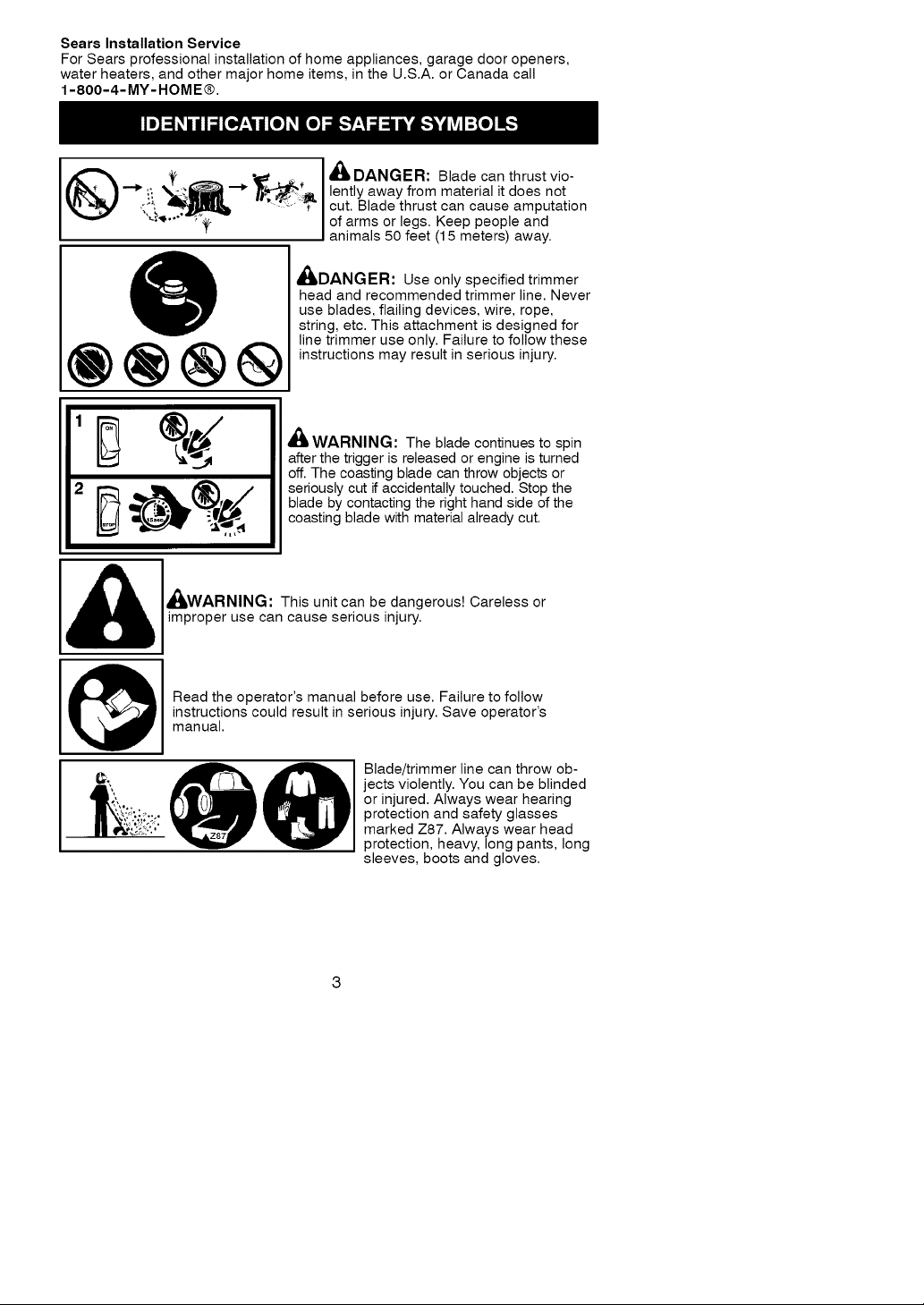
.. ,J ,c_. _/L DANGER: Blade can thrust vio-
.:.!__ ...... -'T" cut. Blade thrust can cause amputation
_*_, lently away from material it does not
of arms or legs. Keep people and
anima s 50 feet (15 meters) away.
A A
_DAN_iER: Use only specified trimmer
head and recommended trimmer line. Never
use blades, flailing devices, wire, rope,
string, etc. This attachment is designed for
line trimmer use only. Failure to follow these
instructions may result in serious injury.
®®®®
WARNING: The blade continues to spin
after the trigger is released or engine is turned
off. The coasting blade can throw objects or
seriously cut if accidentally touched. Stop the
blade by contacting the right hand side of the
coasting blade with material already cut.
improper use can cause serious injury.
_/LWARNING: This unit can be dangerous! Careless or
instructions could result in serious injury. Save operator's
_1 Read the operator's manual before use. Failure to follow
manual.
Blade/trimmer line can throw ob-
jects violently. You can be blinded
or injured. Always wear hearing
protection and safety glasses
marked Z87. Always wear head
protection, heavy, long pants, long
sleeves, boots and gloves.
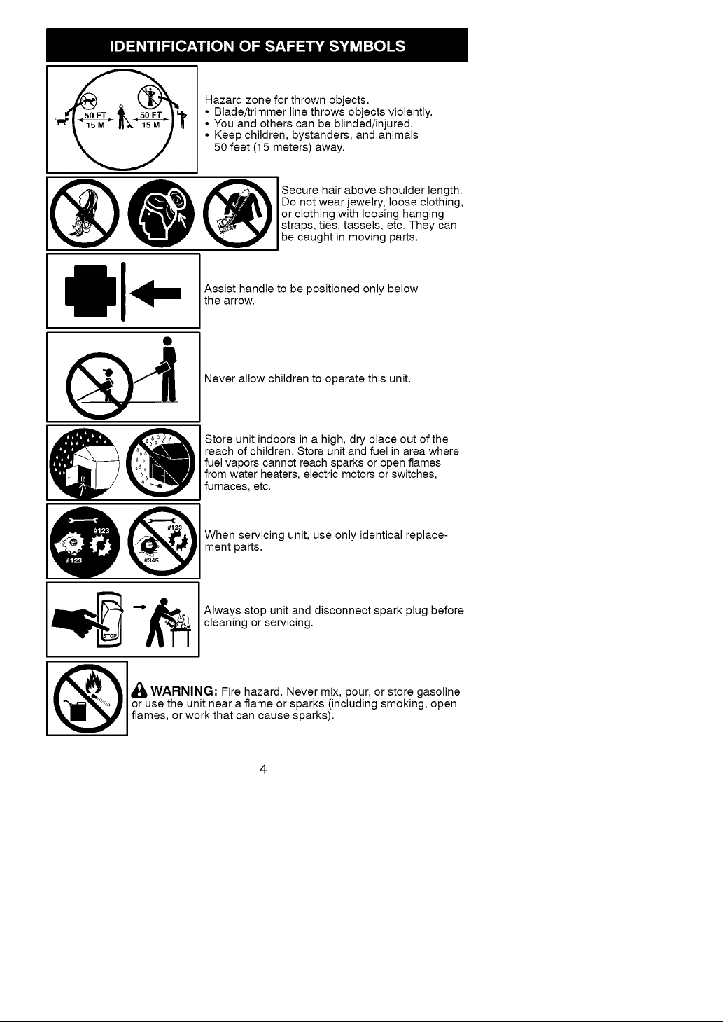
Hazardzoneforthrownobjects.
• Blade/trimmer line throws objects violently.
• You and others can be blinded/injured.
• Keep children, bystanders, and animals
50 feet (15 meters) away.
Do not wear jewelry, loose clothing,
or clothing with loosing hanging
O secureha'rab°vesh°u'der'ength.
Assist handle to be positioned only below
the arrow.
Never allow children to operate this unit.
Store unit indoors in a high, dry place out of the
reach of children. Store unit and fuel in area where
fuel vapors cannot reach sparks or open flames
from water heaters, electric motors or switches,
furnaces, etc.
straps, ties, tassels, etc. They can
be caught in moving parts.
When servicing unit, use only identical replace-
ment parts.
Always stop unit and disconnect spark plug before
cleaning or servicing.
or use the unit near a flame or sparks (including smoking, open
,_k WARNING: Fire hazard. Never mix, pour, or store gasoline
flames, or work that can cause sparks).
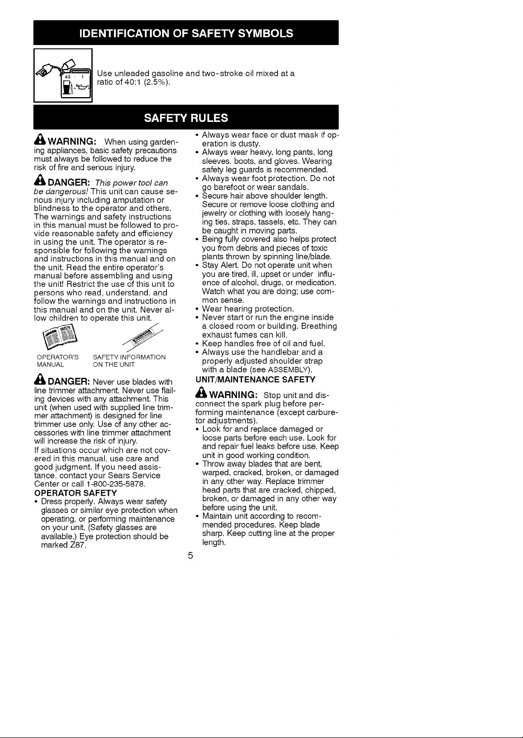
Useunleadedgasolineandtwo-strokeoilmixedata
ratioof40:1(2.5%).
_WARNIN_I:Whenusinggarden-
ingappliances,basicsafetyprecautions
mustalwaysbefollowedtoreducethe
riskoffireandseriousinjury.
_/L DANGER: This power tool can
be dangerous! This unit can cause se-
rious injury including amputation or
blindness to the operator and others.
The warnings and safety instructions
in this manual must be followed to pro-
vide reasonable safety and efficiency
in using the unit. The operator is re-
sponsible for following the warnings
and instructions in this manual and on
the unit. Read the entire operator's
manual before assembling and using
the unit! Restrict the use of this unit to
persons who read, understand, and
follow the warnings and instructions in
this manual and on the unit. Never al-
low children to operate this unit.
OPERATOR'S SAFETY INFORMATION
MANUAL ON THE UNIT
A
4_ DANGER: Never use blades with
line trimmer attachment. Never use flail-
ing devices with any attachment. This
unit (when used with supplied line trim-
mer attachment) is designed for line
trimmer use only. Use of any other ac-
cessories with line trimmer attachment
will increase the risk of injury.
If situations occur which are not cov-
ered in this manual, use care and
good judgment. If you need assis-
tance, contact your Sears Service
Center or call 1-800-235-5878.
OPERATOR SAFETY
• Dress properly. Always wear safety
glasses or similar eye protection when
operating, or performing maintenance
on your unit. (Safety glasses are
available.) Eye protection should be
marked Z87.
• Always wear face or dust mask if op-
eration is dusty.
• Always wear heavy, long pants, long
sleeves, boots, and gloves. Wearing
safety leg guards is recommended.
• Always wear foot protection. Do not
go barefoot or wear sandals.
• Secure hair above shoulder length.
Secure or remove loose clothing and
jewelry or clothing with loosely hang-
ing ties, straps, tassels, etc. They can
be caught in moving parts.
• Being fully covered also helps protect
you from debris and pieces of toxic
plants thrown by spinning line/blade.
• Stay Alert. Do not operate unit when
you are tired, ill, upset or under influ-
ence of alcohol, drugs, or medication.
Watch what you are doing; use com-
mon sense.
• Wear hearing protection.
• Never start or run the engine inside
a closed room or building. Breathing
exhaust fumes can kill.
• Keep handles free of oil and fuel.
• Always use the handlebar and a
properly adjusted shoulder strap
with a blade (see ASSEMBLY).
UNIT/MAINTENANCE SAFETY
_WARNING: Stop unitand dis-
connect the spark plug before per-
forming maintenance (except carbure-
tor adjustments).
• Look for and replace damaged or
loose parts before each use. Look for
and repair fuel leaks before use. Keep
unit in good working condition.
• Throw away blades that are bent,
warped, cracked, broken, or damaged
in any other way. Replace trimmer
head parts that are cracked, chipped,
broken, or damaged in any other way
before using the unit.
• Maintain unit according to recom-
mended procedures. Keep blade
sharp. Keep cutting line at the proper
length.
•UseonlyCraftsmanbrandreplace-
mentline.Neverusewire,rope,
string,etc.
•Installrequiredshieldproperlybefore
usingtheunit.Usethemetalshield
forallmetalbladeuse.Usetheplastic
shieldforalllinetrimmeruse.
•Useonlyspecifiedtrimmerheador
blade;makesureitisproperlyin-
stalledandsecurelyfastened.
•Neverstartenginewithclutchshroud
removed.Theclutchcanflyoffand
causeseriousinjury.
•Besuretrimmerheadorbladestops
turningwhenengineidles.
•Makecarburetoradjustmentswiththe
lowerendsupportedtopreventtrim-
merlineorbladefromcontactingany
object.Holdunitbyhand;donotuse
theshoulderstrapforsupport.
•Keepothersawaywhenmakingcar-
buretoradjustments.
•UseonlyrecommendedCraftsman
accessoriesandreplacementparts.
•Haveallmaintenanceandservicenot
explainedinthismanualperformedby
yourSearsServiceCenter.
FUELSAFETY
•Mixandpourfueloutdoors
•Keepawayfromsparksorflames
•Donotsmokeorallowsmokingnear
fuelortheunitorwhileusingtheunit
•AvoidspillingfueloroilWipeupall
fuelspillsbeforestartingengine
•Moveatleast10feet(3meters)away
fromfuelingsitebeforestartingen-
gine
•Stopengineandallowittocoolbe-
foreremovingfuelcap
•Emptythefueltankbeforestoringor
transportingtheunitUseupfuel]eft
in the carburetor by starting the en-
gine and letting it run until it stops
• Store unit and fuel in area where fuel
vapors cannot reach sparks or open
flames from water heaters, electric
motors or switches, furnaces, etc
• Always store gasoline in a container
approved for flammable liquids
CUTTING SAFETY
_LWARNING: Inspect the area to
be cut before each use Remove ob-
jects (rocks, broken glass, nails, wire,
string, etc.) which can be thrown or be-
come entangled in the blade or trimmer
head
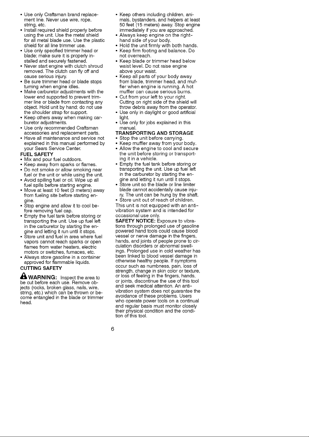
• Keep others including children, ani-
mals, bystanders, and helpers at least
50 feet (15 meters) away. Stop engine
immediately if you are approached.
• Always keep engine on the right-
hand side of your body.
• Hold the unit firmly with both hands.
• Keep firm footing and balance. Do
not overreach.
• Keep blade or trimmer head below
waist level. Do not raise engine
above your waist.
• Keep all parts of your body away
from blade, trimmer head, and muf-
fler when engine is running. A hot
muffler can cause serious burns.
• Cut from your left to your right.
Cutting on right side of the shield will
throw debris away from the operator.
• Use only in daylight or good artificial
light.
• Use only for jobs explained in this
manual.
TRANSPORTING AND STORAGE
• Stop the unit before carrying
• Keep muffler away from your body
• Allow the engine to cool and secure
the unit before storing or transport-
ing it in a vehicle
• Empty the fuel tank before storing or
transporting the unit Use up fuel ]eft
in the carburetor by starting the en-
gine and letting it run until it stops
• Store unit so the blade or line limiter
blade cannot accidentally cause inju-
ry The unit can be hung by the shaft
• Store unit out of reach of children
This unit is not equipped with an anti-
vibration system and is intended for
occasional use only.
SAFETY NOTICE: Exposure to vibra-
tions through prolonged use of gasoline
powered hand tools could cause blood
vessel or nerve damage in the fingers,
hands, and joints of people prone to cir-
culation disorders or abnormal swell-
ings. Prolonged use in cold weather has
been linked to blood vessel damage in
otherwise healthy people. If symptoms
occur such as numbness, pain, loss of
strength, change in skin color or texture,
or loss of feeling in the fingers, hands,
or joints, discontinue the use of this tool
and seek medical attention. An anti-
vibration system does not guarantee the
avoidance of these problems. Users
who operate power tools on a continual
and regular basis must monitor closely
their physical condition and the condi-
tion of this tool.
SPECIALNOTICE:Thisunitisequip-
pedwithatemperaturelimitingmuffler
andsparkarrestingscreenwhichmeets
therequirementsofCaliforniaCodes
4442and4443.AllU.S.forestlandand
thestatesofCalifornia,Idaho,Maine,
Minnesota,NewJersey,Oregon,and
Washingtonrequirebylaw that many
internal combustion engines be
equipped with a spark arresting screen.
If you operate in a locale where such
regulations exist, you are legally re-
sponsible for maintaining the operating
condition of these parts. Failure to do so
is a violation of the law. For normal
homeowner use, the muffler and spark
arresting screen will not require any ser-
vice. After 50 hours of use, we recom-
mend that your muffler be serviced or
replaced by your Sears Service Center.
WARNING: The engine exhaust
from this product contains chemicals
known to the State of California to
cause cancer, birth defects or other
reproductive harm.
CARTON CONTENTS
Check carton contents against the fol-
lowing list.
Model 358,795920
• Powerhead
• Trimmer attachment
• Brushcutter attachment
• aex wrench
• Handlebar
• Bracket cover
• Bracket cover screws (2)
• Plastic shield
• Wing nut (screwed onto shield)
• Shoulder strap with warning
• Container of oil
• Container of line
Examine parts for damage. Do not
use damaged parts.
NOTE: If you need assistance or find
parts missing or damaged, call
1-800-235-5878.
It is normal for the fuel filter to rattle in
the empty fuel tank.
Finding fuel or oil residue on muffler is
normal due to carburetor adjustments
and testing done by the manufacturer.
ASSEMBLY
_WARNING: Always stop unit
and disconnect spark plug before per-
forming any assembly procedures.
_WARNING: If received as-
sembled, repeat all steps to ensure
your unit is properly assembled and all
fasteners are secure.
TOOLS REQUIRED
• Hex Wrench (provided)
• Adjustable Wrench
• Phillips Screwdriver
INSTALLING ATTACHMENT
CAUTION: When installing attach-
ment, place the unit on a flat surface
for stability.
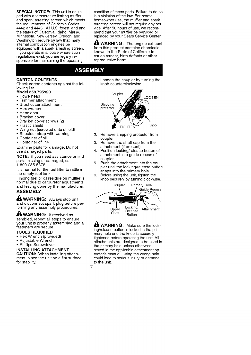
1,
Loosen the coupler by turning the
knob counterclockwise.
Coupler
Shipping
protector
TIGHTEN
2. Remove shipping protector from
coupler.
3. Remove the shaft cap from the
attachment (if present).
4. Position locking/release button of
attachment into guide recess of
coupler.
5. Push the attachment into the cou-
pler until the locking/release button
snaps into the primary hole.
6. Before using the unit, tighten the
knob securely by turning clockwise.
Coupler Primary Hole
_/ Guide Recess
/ Locking/ " "
Upper Release Attachment
Shaft
dlIIWARNING: Make sure the lock-
ing/release button is locked in the pri-
mary hole and the knob is securely
tightened before operating the unit. All
attachments are designed to be used in
the primary hole unless otherwise
stated in the applicable attachment op-
erator's manual. Using the wrong hole
could lead to serious injury or damage
to the unit.
Button
LOOSEN
Knob
Locking/Release
Button in Primary Hole
For assembly of optional attachments
(see list on page 13), refer to the
ASSEMBLY section of the applicable
attachment operator's manual.
ASSEMBLY INFORMATION -
LINE TRIMMER ATTACHMENT
%t TRIMMER
HEAD
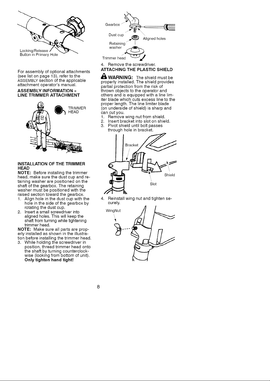
INSTALLATION OF THE TRIMMER
HEAD
NOTE: Before installing the trimmer
head, make sure the dust cup and re-
taining washer are positioned on the
shaft of the gearbox. The retaining
washer must be positioned with the
raised section toward the gearbox.
1. Align hole in the dust cup with the
hole in the side of the gearbox by
rotating the dust cup.
2. Insert a small screwdriver into
aligned holes. This will keep the
shaft from turning while tightening
trimmer head.
NOTE: Make sure all parts are prop-
erly installed as shown in the illustra-
tion before installing the trimmer head.
3. While holding the screwdriver in
position, thread trimmer head onto
the shaft by turning counterclock-
wise (looking from bottom of unit).
Only tighten hand tight!
GearboxJ__
Dust cup _ \
_ Aligned holes
Retaining
washer _,
Trimmer head L_--_J_i,_
4. Remove the screwdriver.
ATTACHING THE PLASTIC SHIELD
_IkWARNING: The shield must be
properly installed. The shield provides
partial protection from the risk of
thrown objects to the operator and
others and is equipped with a line lim-
iter blade which cuts excess line to the
proper length. The line limiter blade
(on underside of shield) is sharp and
can cut you.
1. Remove wing nut from shield.
2. Insert bracket into slot on shield.
3. Pivot shield until bolt )asses
through hole in bracket.
4,
Reinstall wing nut and tighten se-
curely.
4
Shield
Slot
ADJUSTING THE HANDLE
,i_ WARNING: When adjusting the
assist handle, be sure it remains above
the safety label and below the mark or
arrow on the shaft.
1. Loosen wing nut on handle.
2. Rotate the handle on the shaft to an
upright position; retighten wing nut.
ASSEMBLY INFORMATION -
BRUSHCUTTER ATTACHMENT
WEED
BLADE
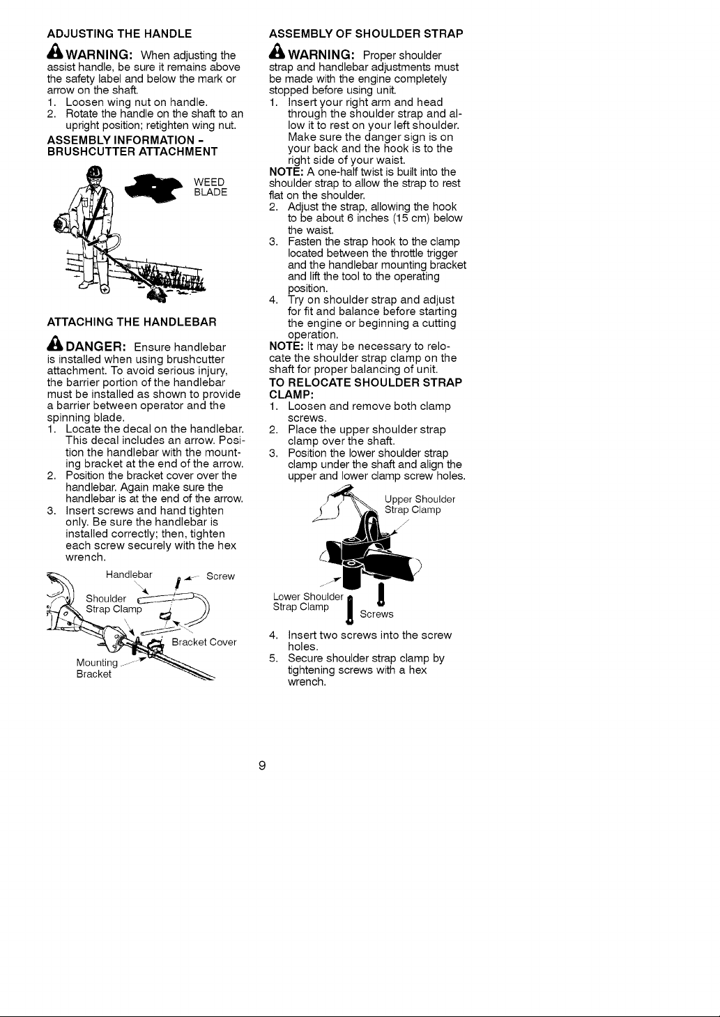
ATTACHING THE HANDLEBAR
_I, DANGER: Ensure handlebar
is installed when using brushcutter
attachment. To avoid serious injury,
the barrier portion of the handlebar
must be installed as shown to provide
a barrier between operator and the
spinning blade.
1. Locate the decal on the handlebar.
This decal includes an arrow. Posi-
tion the handlebar with the mount-
ing bracket at the end of the arrow.
2. Position the bracket cover over the
handlebar. Again make sure the
handlebar is at the end of the arrow.
3. Insert screws and hand tighten
only. Be sure the handlebar is
installed correctly; then, tighten
each screw securely with the hex
wrench.
Handlebar , ,,_---Screw
Shoulder _
trap Clamp _ J)
_ Bracket Cover
Mounting - _"_
Bracket
ASSEMBLY OF SHOULDER STRAP
,I_WARNING: Proper shoulder
strap and handlebar adjustments must
be made with the engine completely
stopped before using unit.
1. Insert your right arm and head
through the shoulder strap and al-
low it to rest on your left shoulder.
Make sure the danger sign is on
your back and the hook is to the
right side of your waist.
NOTE: A one-half twist is built into the
shoulder strap to allow the strap to rest
flat on the shoulder.
2. Adjust the strap, allowing the hook
to be about 6 inches (15 cm) below
the waist.
3. Fasten the strap hook to the clamp
located between the throttle trigger
and the handlebar mounting bracket
and lift the tool to the operating
position.
4. Try on shoulder strap and adjust
for fit and balance before starting
the engine or beginning a cutting
operation.
NOTE: It may be necessary to relo-
cate the shoulder strap clamp on the
shaft for proper balancing of unit.
TO RELOCATE SHOULDER STRAP
CLAMP:
1. Loosen and remove both clamp
screws.
2. Place the upper shoulder strap
clamp over the shaft.
3. Position the lower shoulder strap
clamp under the shaft and align the
upper and lower clamp screw holes.
Upper Shoulder
Strap Clamp
J
j. j_l,-
I
Lower Shoulder II A
Strap Clamp ! Screws
4. Insert two screws into the screw
holes.
5. Secure shoulder strap clamp by
tightening screws with a hex
wrench.
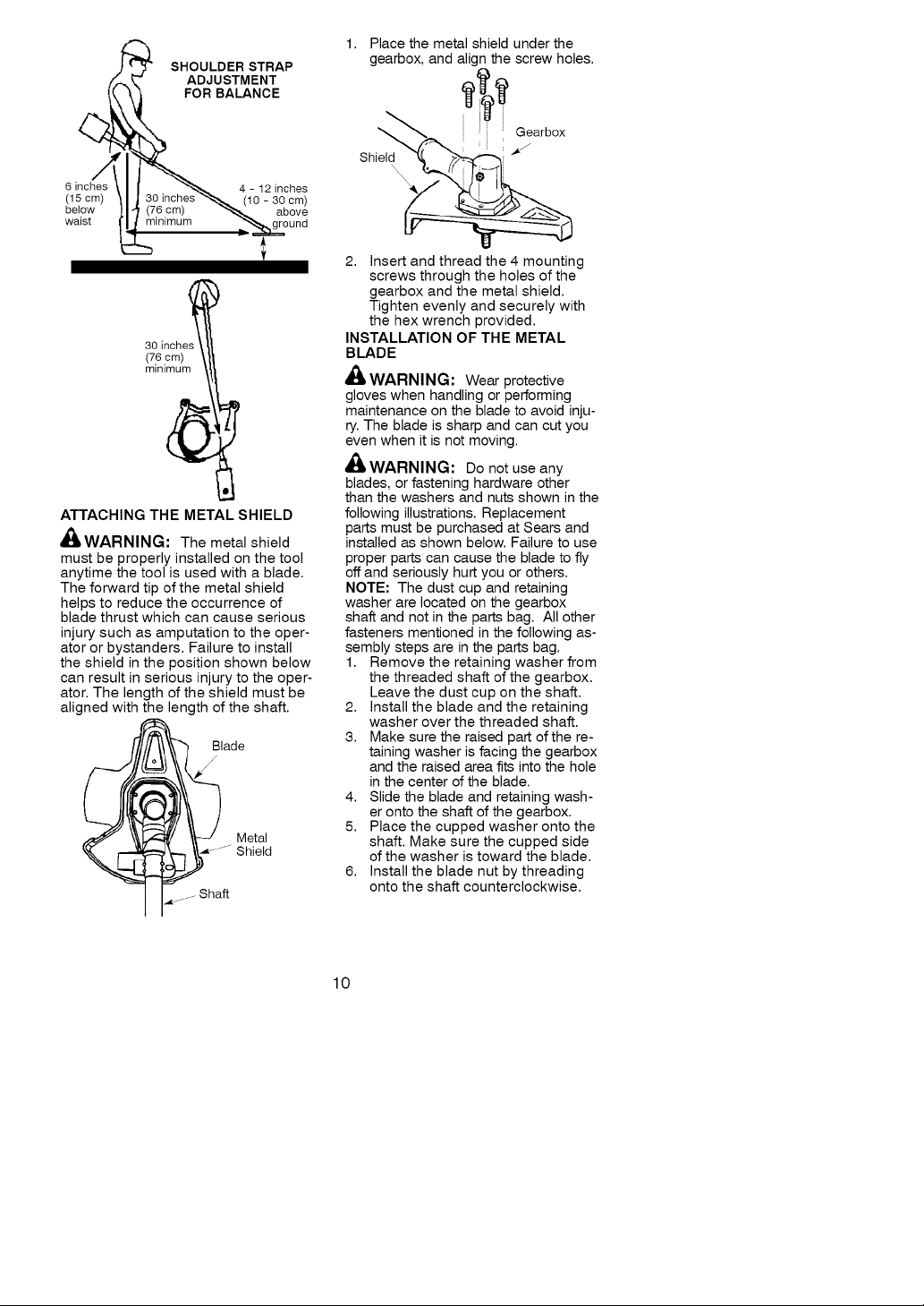
SHOULDER STRAP
ADJUSTMENT
FOR BALANCE
1. Place the metal shield under the
gearbox, and align the screw holes.
.'-..
6 inches 4 - 12 inches
(15 cm) (10 - 30 cm)
below above
waist round
30 inches
(76 cm)
minimum
ATTACHING THE METAL SHIELD
,_IkWARNING: The metal shield
must be properly installed on the tool
anytime the tool is used with a blade.
The forward tip of the metal shield
helps to reduce the occurrence of
blade thrust which can cause serious
injury such as amputation to the oper-
ator or bystanders. Failure to install
the shield in the position shown below
can result in serious injury to the oper-
ator. The length of the shield must be
aligned with the length of the shaft.
lade
I p Sha
ShielX ; i
2. Insert and thread the 4 mounting
screws through the holes of the
gearbox and the metal shield.
Tighten evenly and securely with
the hex wrench provided.
INSTALLATION OF THE METAL
BLADE
'_ WARNING: Wear protective
gloves when handling or performing
maintenance on the blade to avoid inju-
ry. The blade is sharp and can cut you
even when it is not moving.
_,WARNING: Do not use any
blades, or fastening hardware other
than the washers and nuts shown in the
following illustrations. Replacement
parts must be purchased at Sears and
installed as shown below. Failure to use
proper parts can cause the blade to fly
off and seriously hurt you or others.
NOTE: The dust cup and retaining
washer are located on the gearbox
shaft and not in the parts bag. All other
fasteners mentioned in the following as-
sembly steps are in the parts bag.
1. Remove the retaining washer from
the threaded shaft of the gearbox.
Leave the dust cup on the shaft.
2. Install the blade and the retaining
washer over the threaded shaft.
3. Make sure the raised part of the re-
taining washer is facing the gearbox
and the raised area fits into the hole
in the center of the blade.
4. Slide the blade and retaining wash-
er onto the shaft of the gearbox.
5. Place the cupped washer onto the
shaft. Make sure the cupped side
of the washer is toward the blade.
6. Install the blade nut by threading
onto the shaft counterclockwise.
10
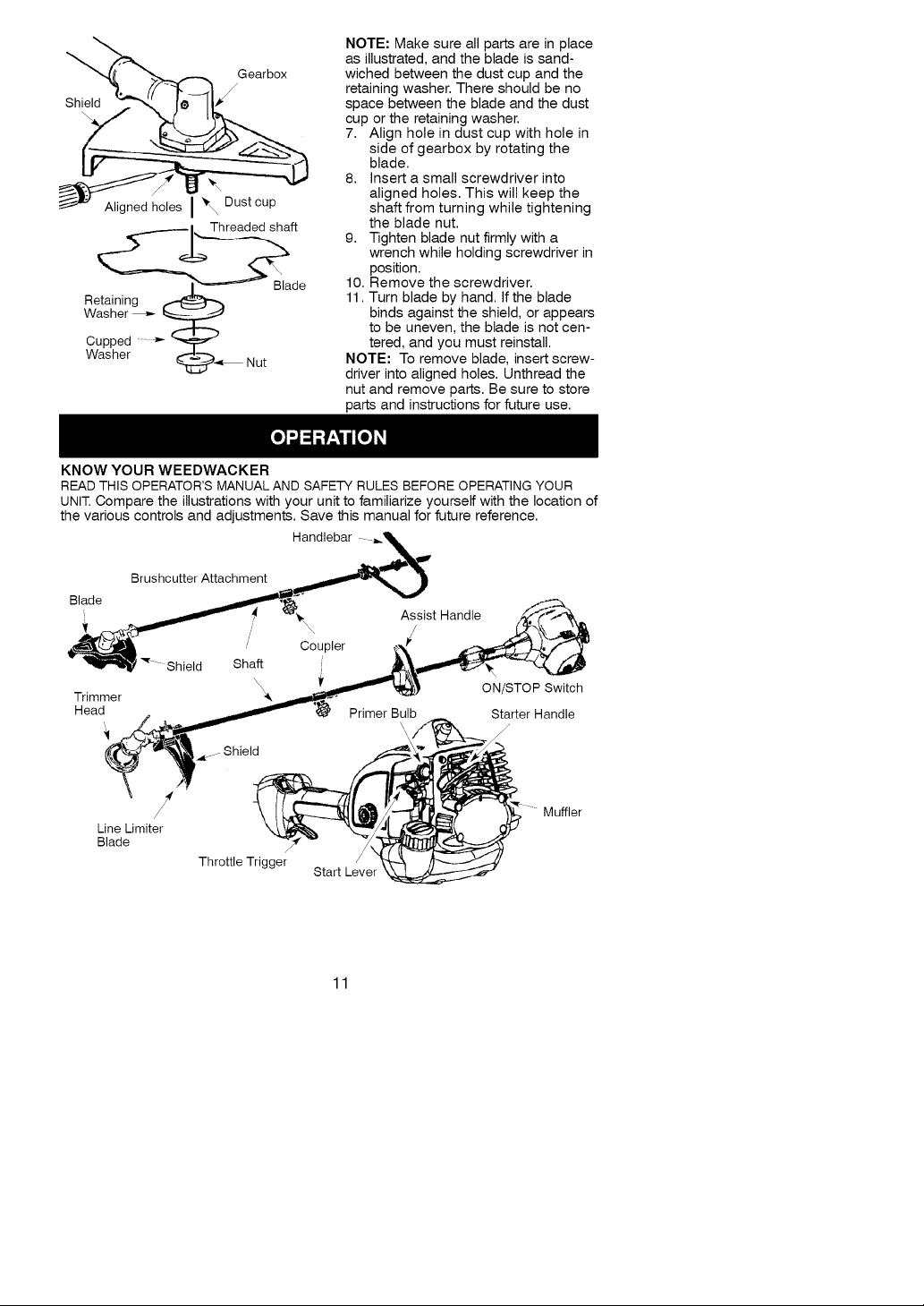
NOTE: Make sure all parts are in place
Gearbox
/
Shield
as illustrated, and the blade is sand-
wiched between the dust cup and the
retaining washer. There should be no
space between the blade and the dust
cup or the retaining washer.
7. Align hole in dust cup with hole in
side of gearbox by rotating the
blade.
8. Insert a small screwdriver into
aligned holes. This will keep the
Aligned holes J _ Dust cup
_l Threaded shaft
shaft from turning while tightening
the blade nut.
9. Tighten blade nut firmly with a
wrench while holding screwdriver in
position.
Re_ de
Washer _
Cupped ....._
Washer _i_-,t Nut
10. Remove the screwdriver.
11. Turn blade by hand. If the blade
binds against the shield, or appears
to be uneven, the blade is not cen-
tered, and you must reinstall.
NOTE: To remove blade, insert screw-
driver into aligned holes. Unthread the
nut and remove parts. Be sure to store
parts and instructions for future use.
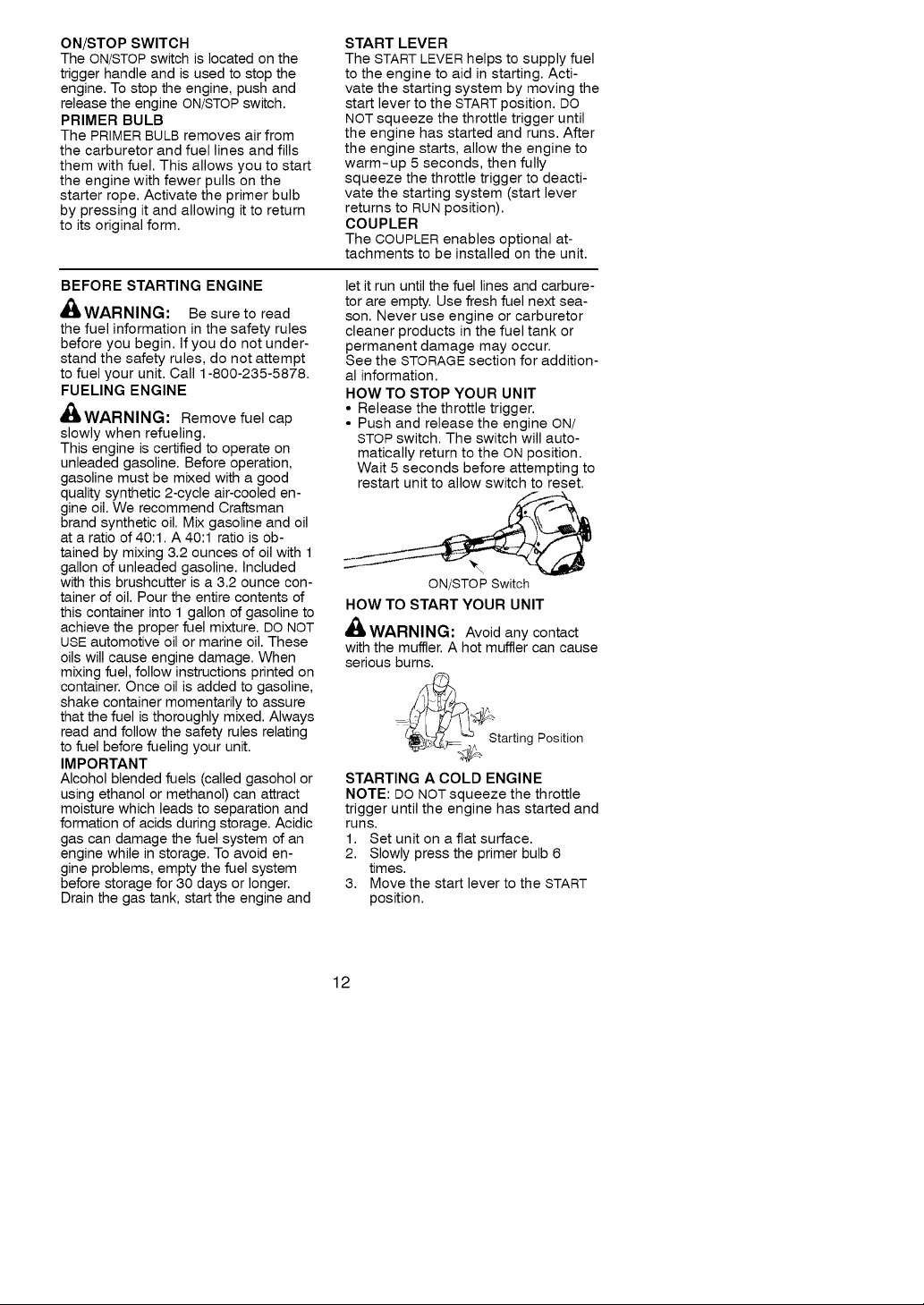
KNOW YOUR WEEDWACKER
READ THIS OPERATOR'S MANUAL AND SAFETY RULES BEFORE OPERATING YOUR
UNIT.Compare the illustrations with your unit to familiarize yourself with the location of
the various controls and adjustments. Save this manual for future reference.
Handlebar
Brushcutter Attachment
Blade
Assist Handle __
_' \ / (2"i\\ ._._
_ Coupler _,_k __,_
_1 Shield Shaft i _'__
_. _. __) ON/STOP Switch
I_reJamdmer. _" Primer B_lb Starter Handle
.,_ --Shield
/ Muffler
Line Limiter
Blade
Throttle Trigger /
Start Lever
11
ON/STOP SWITCH
The ON/STOP switch is located on the
trigger handle and is used to stop the
engine. To stop the engine, push and
release the engine ON/STOPswitch.
PRIMER BULB
The PRIMER BULB removes air from
the carburetor and fuel lines and fills
them with fuel. This allows you to start
the engine with fewer pulls on the
starter rope. Activate the primer bulb
by pressing it and allowing it to return
to its original form.
START LEVER
The START LEVER helps to supply fuel
to the engine to aid in starting. Acti-
vate the starting system by moving the
start lever to the START position. DO
NOT squeeze the throttle trigger until
the engine has started and runs. After
the engine starts, allow the engine to
warm-up 5 seconds, then fully
squeeze the throttle trigger to deacti-
vate the starting system (start lever
returns to RUN position).
COUPLER
The COUPLER enables optional at-
tachments to be installed on the unit.
BEFORE STARTING ENGINE
_ILWARNING: Be sureto read
the fuel information in the safety rules
before you begin. If you do not under-
stand the safety rules, do not attempt
to fuel your unit. Call 1-800-235-5878.
FUELING ENGINE
_ILWARNING: Remove fuel cap
slowly when refueling.
This engine is certified to operate on
unleaded gasoline. Before operation,
gasoline must be mixed with a good
quality synthetic 2-cycle air-cooled en-
gine oil. We recommend Craftsman
brand synthetic oil. Mix gasoline and oil
at a ratio of 40:1. A 40:1 ratio is ob-
tained by mixing 3.2 ounces of oil with 1
gallon of unleaded gasoline. Included
with this brushcutter is a 3.2 ounce con-
tainer of oil. Pour the entire contents of
this container into 1 gallon of gasoline to
achieve the proper fuel mixture. DO NOT
USE automotive oil or marine oil. These
oils will cause engine damage. When
mixing fuel, follow instructions printed on
container. Once oil is added to gasoline,
shake container momentarily to assure
that the fuel is thoroughly mixed. Always
read and follow the safety rules relating
to fuel before fueling your unit.
IMPORTANT
Alcohol blended fuels (called gasohol or
using ethanol or methanol) can attract
moisture which leads to separation and
formation of acids during storage. Acidic
gas can damage the fuel system of an
engine while in storage. To avoid en-
gine problems, empty the fuel system
before storage for 30 days or longer.
Drain the gas tank, start the engine and
let it run until the fuel lines and carbure-
tor are empty. Use fresh fuel next sea-
son. Never use engine or carburetor
cleaner products in the fuel tank or
permanent damage may occur.
See the STORAGE section for addition-
al information.
HOW TO STOP YOUR UNIT
• Release the throttle trigger.
• Push and release the engine ON/
STOP switch. The switch will auto-
matically return to the ON position.
Wait 5 seconds before attempting to
restart unit to allow switch to reset.
ON/STOP Switch
HOW TO START YOUR UNIT
WARNING: Avoid any contact
with the muffler. A hot muffler can cause
serious burns.
Starting Position
STARTING A COLD ENGINE
NOTE: DO NOT squeeze the throttle
trigger until the engine has started and
runs.
1. Set unit on a flat surface.
2. Slowly press the primer bulb 6
times.
3. Move the start lever to the START
position.
12
Primer Bulb
Starter Handle
\
Start Lever
4. This unit has the Sim-pulTM starting
system. You do not have to pull the
starter rope handle sharply or brisk-
ly. Pull starter rope handle with a
controlled and steady motion until
engine starts and runs.
5. Allow unit to run for 5 seconds, then
fully squeeze the throttle trigger to
disengage the starting system (start
lever returns to RUN position) and
begin normal operation.
STARTING A WARM ENGINE
Pull starter rope handle with a con-
trolled and steady motion until engine
starts and runs.
NOTE: Normally, the warm starting
procedure can be used within 5-10
minutes after the unit is turned off. If
the unit sits for more than 10 minutes
without being used, it will be neces-
sary to start the unit by following the
steps under STARTING A COLD EN-
GINE or following the starting instruc-
tion steps shown on the unit.
STARTING A FLOODED ENGINE
Flooded engines can be started by
placing the start lever in the RUN posi-
tion. Fully squeeze throttle trigger.
Pull the starter handle repeatedly
while squeezing throttle trigger until
engine starts and runs. This could re-
quire pulling the starter handle many
times, depending on how badly the
unit is flooded. If the unit still doesn't
start, refer to TROUBLESHOOTING
TABLE or call 1-800-235-5878.
CRAFTSMAN ®
CONVERTIBLE TM FEATURE
This model is equipped with a coupler
which enables optional attachments to
be installed. The optional attachments
are:
Edger ................. 358.79240
Cultivator .............. 358.79241
Blower ................ 358.79242
Brushcutter ............ 358.79244
Pruner ................ 358.79245
Muffler
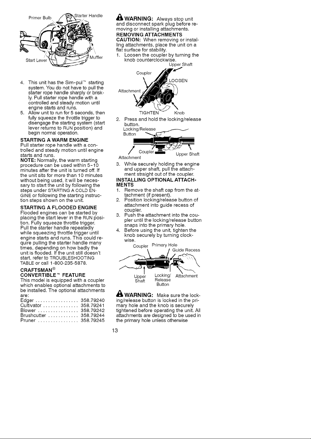
,_ WARNING: Always stop unit
and disconnect spark plug before re-
moving or installing attachments.
REMOVING ATTACHMENTS
CAUTION: When removing or instal-
ling attachments, place the unit on a
flat surface for stability.
1. Loosen the coupler by turning the
knob counterclockwise.
Coupler
Attachment
Upper Shaft
LOOSEN
\
TIGHTEN Knob
2,
Press and hold the locking/release
button.
Locking/Release
Button
Attachment
3. While securely holding the engine
INSTALLING OPTIONAL ATTACH-
MENTS
1. Remove the shaft cap from the at-
2. Position locking/release button of
3. Push the attachment into the cou-
4. Before using the unit, tighten the
,_WARNING: Make surethe lock-
ing/release button is locked in the pri-
mary hole and the knob is securely
tightened before operating the unit. All
attachments are designed to be used in
the primary hole unless otherwise
13
Cou_ Upper Shaft
and upper shaft, pull the attach-
ment straight out of the coupler.
tachment (if present).
attachment into guide recess of
coupler.
pler until the locking/release button
snaps into the primary hole.
knob securely by turning clock-
wise.
Coupler Primary Hole
Upper Locking/ Attachment
Shaft Release
Guide Recess
Button
stated in the applicable attachment op-
erator's manual. Using the wrong hole
could lead to serious injury or damage
to the unit.
Locking/Release
Button in Primary Hole
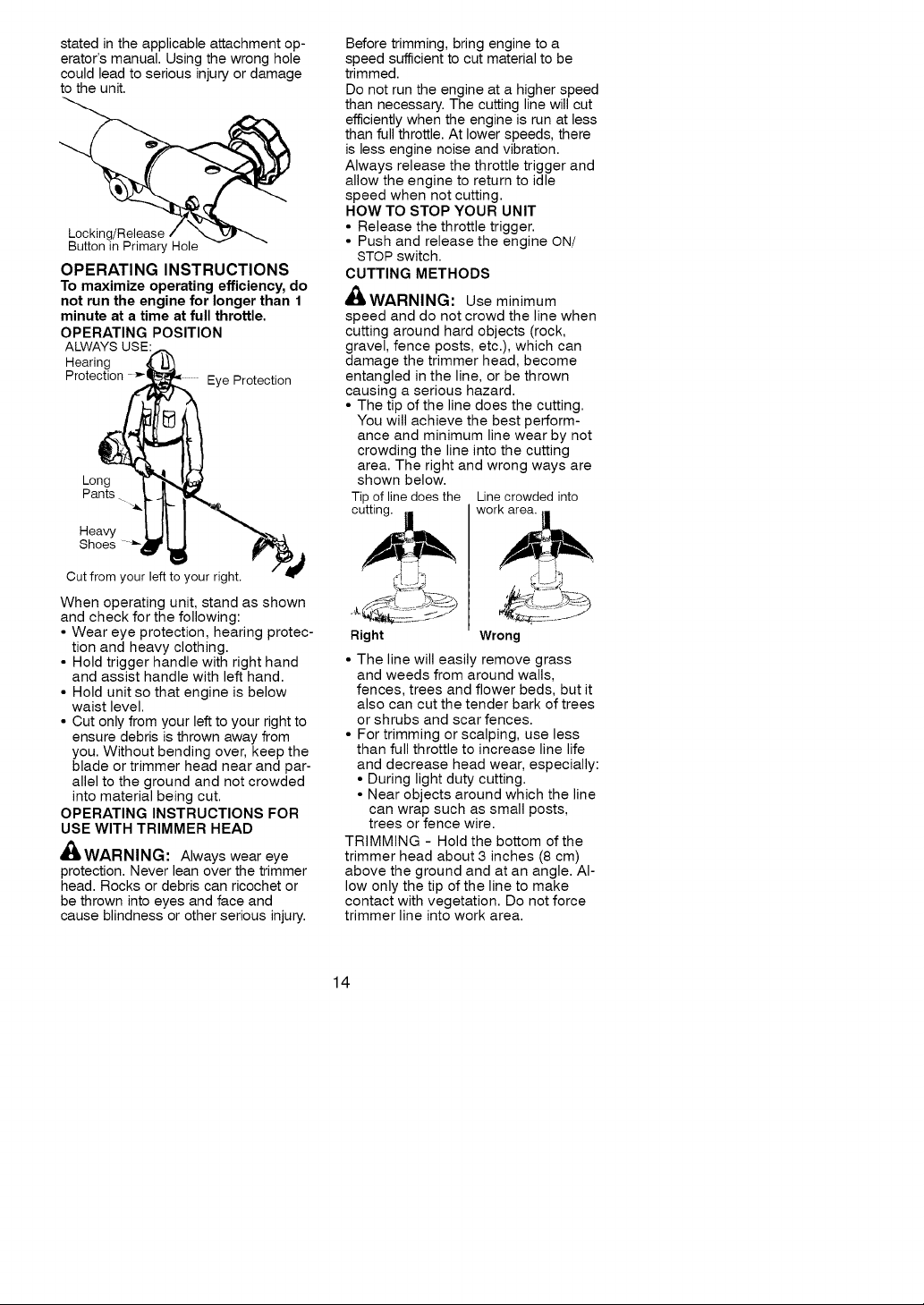
OPERATING INSTRUCTIONS
To maximize operating efficiency, do
not run the engine for longer than 1
minute at a time at full throttle.
OPERATING POSITION
ALWAYS USE:
Hearing J-t
Protection Eye Protection
Long
Pants
Shoes
Heavy _,I_
Cutfrom yourle_to yourright.
When operating unit, stand as shown
and check for the following:
• Wear eye protection, hearing protec-
tion and heavy clothing.
• Hold trigger handle with right hand
and assist handle with left hand.
• Hold unit so that engine is below
waist level.
• Cut only from your left to your right to
ensure debris is thrown away from
you. Without bending over, keep the
blade or trimmer head near and par-
allel to the ground and not crowded
into material being cut.
OPERATING INSTRUCTIONS FOR
USE WITH TRIMMER HEAD
WAR NI N G: Always wear eye
protection. Never lean over the trimmer
head. Rocks or debris can ricochet or
be thrown into eyes and face and
cause blindness or other serious injury.
Before trimming, bring engine to a
speed sufficient to cut material to be
trimmed.
Do not run the engine at a higher speed
than necessary. The cutting line will cut
efficiently when the engine is run at less
than full throttle. At lower speeds, there
is less engine noise and vibration.
Always release the throttle trigger and
allow the engine to return to idle
speed when not cutting.
HOW TO STOP YOUR UNIT
• Release the throttle trigger.
• Push and release the engine ON/
STOP switch.
CUTTING METHODS
4(_WARNING: Use minimum
speed and do not crowd the line when
cutting around hard objects (rock,
gravel, fence posts, etc.), which can
damage the trimmer head, become
entangled in the line, or be thrown
causing a serious hazard.
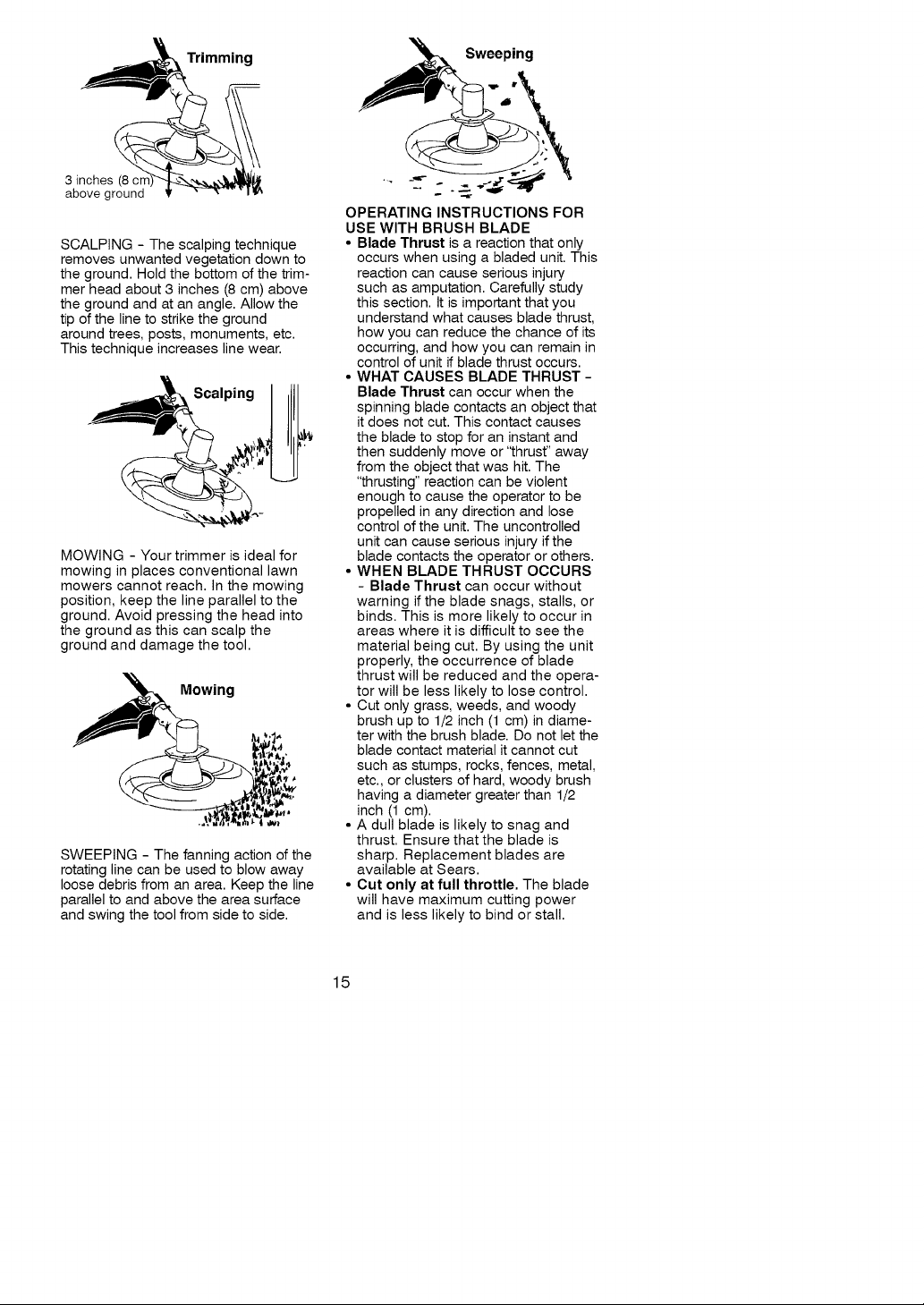
• The tip of the line does the cutting.
You will achieve the best perform-
ance and minimum line wear by not
crowding the line into the cutting
area. The right and wrong ways are
shown below.
Tip of line does the Line crowded into
cutting, worl
Right Wrong
• The line will easily remove grass
and weeds from around walls,
fences, trees and flower beds, but it
also can cut the tender bark of trees
or shrubs and scar fences.
• For trimming or scalping, use less
than full throttle to increase line life
and decrease head wear, especially:
• During light duty cutting.
• Near objects around which the line
can wrap such as small posts,
trees or fence wire.
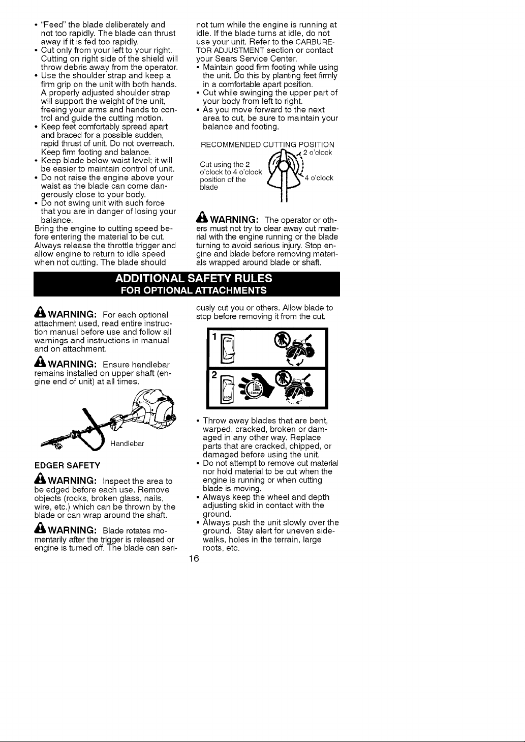
TRIMMING - Hold the bottom of the
trimmer head about 3 inches (8 cm)
above the ground and at an angle. Al-
low only the tip of the line to make
contact with vegetation. Do not force
trimmer line into work area.
14
Trimming
3 inches (8 cn
above ground
SCALPING - The scalping technique
removes unwanted vegetation down to
the ground. Hold the bottom of the trim-
mer head about 3 inches (8 cm) above
the ground and at an angle. Allow the
tip of the line to strike the ground
around trees, posts, monuments, etc.
This technique increases line wear.
Scalping
MOWING - Your trimmer is ideal for
mowing in places conventional lawn
mowers cannot reach. In the mowing
position, keep the line parallel to the
ground. Avoid pressing the head into
the ground as this can scalp the
ground and damage the tool.
Mowing
SWEEPING - The fanning action of the
rotating line can be used to blow away
loose debris from an area. Keep the line
parallel to and above the area surface
and swing the tool from side to side.
Sweeping
OPERATING INSTRUCTIONS FOR
USE WITH BRUSH BLADE
• Blade Thrust is a reaction that only
occurs when using a bladed unit. This
reaction can cause serious injury
such as amputation. Carefully study
this section. It is important that you
understand what causes blade thrust,
how you can reduce the chance of its
occurring, and how you can remain in
control of unit if blade thrust occurs.
• WHAT CAUSES BLADE THRUST -
Blade Thrust can occur when the
spinning Made contacts an object that
it does not cut. This contact causes
the Made to stop for an instant and
then suddenly move or 'thrust" away
from the object that was hit. The
"thrusting" reaction can be violent
enough to cause the operator to be
propelled in any direction and lose
control of the unit. The uncontrolled
unit can cause serious injury if the
blade contacts the operator or others.
• WHEN BLADE THRUST OCCURS
- Blade Thrust can occur without
warning if the Made snags, stalls, or
binds. This is more likely to occur in
areas where it is difficult to see the
material being cut. By using the unit
properly, the occurrence of blade
thrust will be reduced and the opera-
tor will be less likely to lose control.
• Cut only grass, weeds, and woody
brush up to 1/2 inch (1 cm) in diame-
ter with the brush blade. Do not let the
Made contact material it cannot cut
such as stumps, rocks, fences, metal,
etc., or clusters of hard, woody brush
having a diameter greater than 1/2
inch (1 cm).
• A dull blade is likely to snag and
thrust. Ensure that the blade is
sharp. Replacement blades are
available at Sears.
• Cut only at full throttle. The blade
will have maximum cutting power
and is less likely to bind or stall.
15
• "Feed" the blade deliberately and
not too rapidly. The blade can thrust
away if it is fed too rapidly.
• Cut only from your left to your right.
Cutting on right side of the shield will
throw debris away from the operator.
• Use the shoulder strap and keep a
firm grip on the unit with both hands.
A properly adjusted shoulder strap
will support the weight of the unit,
freeing your arms and hands to con-
trol and guide the cutting motion.
• Keep feet comfortably spread apart
and braced for a possible sudden,
rapid thrust of unit. Do not overreach.
Keep firm footing and balance.
• Keep blade below waist level; it will
be easier to maintain control of unit.
• Do not raise the engine above your
waist as the blade can come dan-
gerously close to your body.
• Do not swing unit with such force
that you are in danger of losing your
balance.
Bring the engine to cutting speed be-
fore entering the material to be cut.
Always release the throttle trigger and
allow engine to return to idle speed
when not cutting. The blade should
_WARNING: For each optional
attachment used, read entire instruc-
tion manual before use and follow all
warnings and instructions in manual
and on attachment.
,_WARNING: Ensure handlebar
remains installed on upper shaft (en-
gine end of unit) at all times.
not turn while the engine is running at
idle. If the blade turns at idle, do not
use your unit. Refer to the CARBURE-
TOR ADJUSTMENT section or contact
your Sears Service Center.
• Maintain good firm footing while using
the unit. Do this by planting feet firmly
in a comfortable apart position.
• Cut while swinging the upper part of
your body from left to right.
• As you move forward to the next
area to cut, be sure to maintain your
balance and footing.
RECOMMENDED CUTTING POSITION
Cut using the 2
o'clock to 4 o'clock
position of the / _ %'€'4o'clock
blade
2 o'clock
'lr-
,_ WARNING:
ers must not try to clear away cut mate-
rial with the engine running or the blade
turning to avoid serious injury. Stop en-
gine and blade before removing materi-
als wrapped around blade or shaft.
ousl
cut you or others. Allow blade to
sto
before removing it from the cut.
The operator or oth-
%, •
EDGER SAFETY
'_ WARNING: Inspect the area to
be edged before each use. Remove
objects (rocks, broken glass, nails,
wire, etc.) which can be thrown by the
blade or can wrap around the shaft.
_WARNING: Blade rotates mo-
mentarily after the trigger is released or
engine is turned off. The blade can seri-
• Throw away blades that are bent,
warped, cracked, broken or dam-
aged in any other way. Replace
parts that are cracked, chipped, or
damaged before using the unit.
• Do not attempt to remove cut material
nor hold material to be cut when the
engine is running or when cutting
blade is moving.
• Always keep the wheel and depth
adjusting skid in contact with the
ground.
• Always push the unit slowly over the
ground. Stay alert for uneven side-
walks, holes in the terrain, large
roots, etc.
16

BLOWER/VACUUM SAFETY
_WARNING: Inspect area before
starting unit. Remove all debris and
hard objects such as rocks, glass,
wire, etc. that can ricochet, be thrown,
or otherwise cause injury or damage
during operation.
• Do not set unit on any surface except
a clean, hard area while engine is
running. Debris such as gravel, sand,
dust, grass, etc., could be picked up
by the air intake and thrown out
through discharge opening, damaging
unit, property, or causing serious injury
to bystanders or operator.
• Never place objects inside the blow-
er tubes, vacuum tubes or blower
outlet. Always direct the blowing de-
bris away from people, animals,
glass, and solid objects such as
trees, automobiles, walls, etc. The
force of air can cause rocks, dirt, or
sticks to be thrown or to ricochet
which can hurt people or animals,
break glass, or cause other damage.
• Never run unit without the proper
equipment attached. When using
your unit as a blower, always install
blower tubes.
• Check air intake opening, blower
tubes or vacuum tubes frequently,
always with engine stopped and
spark plug disconnected. Keep
vents and discharge tubes free of
debris which can accumulate and
restrict proper air flow.
• Never place any object in air intake
opening as this could restrict proper
air flow and cause damage to the unit.
• Never use for spreading chemicals,
fertilizers, or other substances which
may contain toxic materials.
• To avoid spreading fire, do not use
near leaf or brush fires, fireplaces,
barbecue pits, ashtrays, etc.
CULTIVATOR SAFETY
_,WARNING: Rotating tines can
cause serious injury. Keep away from
rotating tines. Stop the engine and dis-
connect the spark plug before unclog-
ging tines or making repairs.
,_ WARNING: Inspect the area to
be cultivated before starting the unit.
Remove all debris and hard and sharp
objects such as rocks, vines,
branches, rope, string, etc.
• Avoid heavy contact with solid objects
that might stop the tines. If heavy con-
tact occurs, stop the engine and in-
spect the unit for damage.
• Never operate the cultivator without
the tine cover in place and properly
secured.
• Keep the tines and guard clear of
debris.
• After striking a foreign object, stop
the engine, disconnect the spark
plug and inspect the cultivator for
damage. Repair before restarting.
• Disconnect attachment from the drive
engine before cleaning the tines with
a hose and water to remove any
build-up. Oil the tines to prevent rust.
• Always wear gloves when servicing or
cleaning the tines. The tines become
very sharp from use.
• Do not run unit at high speed unless
cultivating.
HEDGE TRIMMER SAFETY
DANGER: RISK OF CUT KEEP
HANDS AWAY FROM BLADE - Blade
moves momentarily after the trigger is
released or engine is turned off. Do not
attempt to clear away cut material when
the blade is in motion. Make sure en-
gine is turned off, the spark plug wire is
disconnected, and the blade has
stopped moving before removing
jammed material from the cutting blade.
Do not grab or hold the unit by the cut-
ting blade.
lID ®
1_1111111111_
!............ !
,_ WARNING: Inspect the area be-
fore starting the unit. Remove all de-
bris and hard objects such as rocks,
glass, wire, etc. that can ricochet, be
thrown, or otherwise cause injury or
damage during operation.
• Do not use a cutting blade that is
bent, warped, cracked, broken or
damaged in any other way. Have
17

wornordamagedpartsreplacedby
anauthorizedservicedealer.
•Alwayskeepunitinfrontofyour
body.Keepallpartsofyourbody
awayfromthecuttingblade.
• Keepthecuttingbladeandairvents
clearofdebris.
POLEPRUNERSAFETY
'_ WARNING: The reciprocating
Made/ rotating chain can cause se-
vere injury. Inspect the unit before
use. Do not operate unit with a bent,
cracked or dull blade or dull chain.
Keep away from the blade/chain.
WARNING: The reciprocating
blade/rotating chain is sharp. Do not
touch. To prevent serious injury, always
stop engine and ensure blade/chain
has stopped moving, disconnect spark
plug, and wear gloves when changing
or handling the blade or chain.
WAR NI N G: A coasting blade/ro-
tating chain can cause injury while it
continues to move after the engine is
stopped. Maintain proper control of the
unit until the blade/chain has completely
stopped moving. Keep hands, face and
feet at a distance from all moving parts.
Do not attempt to touch or stop the
blade or chain when it is moving.
WARNING: Keep the pruner
away from power lines or electrical
wires.
• Only use for pruning limbs or
branches up to 6 inches (15 cm) in
diameter.
• Do not operate the unit faster than
the speed needed to prune. Do not
run the unit at high speed when not
pruning.
• Always stop the unit when work is
delayed or when walking from one
cutting location to another.
• If you strike or become entangled
with a foreign object, stop the engine
immediately and check for damage.
Have any damage repaired by an
authorized service dealer before at-
tempting further operations. Discard
blades that are bent, warped,
cracked or broken.
• Stop the unit immediately if you feel
excessive vibration. Vibration is a sign
of trouble. Inspect thoroughly for loose
nuts, bolts or damage before continu-
ing. Contact an authorized service
dealer for repair or replacement of af-
fected parts as necessary.
SNOW THROWER SAFETY
WARNING: Keep hands and
feet away from the rotor when starting
or running the engine. Never attempt
to clear the rotor with the engine run-
ning. Stop engine and disconnect
spark plug before unclogging snow or
debris from discharge chute or when
adjusting vanes.
,_LWARNING: Falling objects can
cause severe head injury. Wear head
protection when operating this unit
with a pole pruner attachment.
WAR NI N G: To prevent serious
injury, do not use more than one boom
extension with a pole pruner attach-
ment.
Z_
_,WARNING: Never lean over dis-
charge chute. Rocks or debris could
be thrown into the eyes and face and
cause serious injury or blindness.
,_ WARNING: Inspect the area
where the unit is to be used. Remove
objects that could be thrown or dam-
age the unit. Some objects may be
hidden by fallen snow - be alert for
the possibility.
• Direct material discharge away from
glass enclosures, automobiles, etc.
18

• Do not run engine at high speed
while not removing snow.
• Be attentive when using the snow-
thrower, and stay alert for holes in the
terrain and other hidden hazards.
• Make sure the rotor will spin freely be-
fore attaching the snowthrower to the
powerhead.
• If the rotor will not rotate freely due
to frozen ice, thaw the unit before
thoroughly before attempting to op-
erate under power.
• Keep the rotor clear of debris.
• Do not throw snow near other
people. The snow thrower could pro-
pel small objects at high speed
causing injury.
• After striking a foreign object, stop
the engine, disconnect spark plug
and inspect the snowthrower for
damage and repair if necessary be-
fore restarting unit.
MAINTENANCE SCHEDULE
,_ WARNING: Disconnect the spark plug before performing maintenance
except for carburetor adjustments.
CARE & MAINTENANCE TASK
Check for loose fasteners and parts
Check for damaged or worn parts
Inspect and clean unit and decals
Clean air filter
Inspect muffler and spark arresting screen
Replace spark plug
• Never operate the snowthrower near
glass enclosures, automobiles and
trucks.
• Never attempt to use the snow-
thrower on a roof.
• Never operate the snowthrower near
window wells, dropoffs, etc.
• Never discharge snow onto public
roads or near moving traffic.
• Clear snow from slopes by going up
and down; never across. Use cau-
tion when changing directions. Nev-
er clear snow from steep slopes.
• Let snowthrower run for a few min-
utes after clearing snow so moving
parts do not freeze.
• Look behind and use care when
backing up. Exercise caution to avoid
slipping or falling, especially when op-
erating in reverse.
• Know how to stop quickly.
WHEN TO PERFORM
Before each use
Before each use
After each use
Every 5 hours of operation
Every 50 hours of operation
Yearly
GENERAL RECOMMENDATIONS
The warranty on this unit does not
cover items that have been subjected
to operator abuse or negligence. To
receive full value from the warranty,
the operator must maintain unit as
instructed in this manual. Various ad-
justments will need to be made peri-
odically to properly maintain your unit.
CHECK FOR LOOSE
FASTENERS AND PARTS
• Spark Plug Boot
• Air Filter
• Housing Screws
• Assist Handle Screw
• Debris Shield
• Blade Nut
CHECK FOR DAMAGED OR
WORN PARTS
Contact Sears Service Center for re-
placement of damaged or worn parts.
• ON/STOP Switch - Ensure ON/STOP
switch functions properly by pushing
and releasing the switch. Make sure
engine stops. Wait 5 seconds before
attempting to restart unit to allow
switch to reset. Restart engine and
continue.
• Fuel Tank - Discontinue use of unit
if fuel tank shows signs of damage
or leaks.
• Debris Shield - Discontinue use of
unit if debris shield is damaged.
• Blade - Discontinue use of unit if
blade becomes damaged or worn.
INSPECT AND CLEAN UNIT AND
DECALS
• After each use, inspect complete
unit for loose or damaged parts.
Clean the unit and decals using a
damp cloth with a mild detergent.
• Wipe off unit with a clean dry cloth.
19

CLEANAIRFILTER
Adirtyairfilterdecreasesengineper-
formanceandincreasesfuelcon-
sumptionandharmfulemissions.Al-
wayscleanafterevery5hoursof
operation.
1. Cleanthecoverandthearea
aroundittokeepdirtfromfalling
intothecarburetorchamberwhen
thecoverisremoved.
2. Loosenknob.Removeairfilter
coverandairfilter.
NOTE:Toavoidcreatingafirehazard
orproducingharmfulevaporative
emissions,donotcleanfilteringaso-
lineorotherflammablesolvent.
3. Washthefilterinsoapandwater.
4. Allowfiltertodry.
5. Replaceparts.
Air Filter
/
V
Air Filter Cover
Knob
INSPECT MUFFLER AND SPARK
ARRESTING SCREEN
_, WARNING: The muffler on this
product contains chemicals known to
the State of California to cause cancer.
As your unit is used, carbon deposits
build up on the muffler and spark ar-
resting screen.
For normal homeowner use, however,
the muffler and spark arresting screen
will not require any service. After 50
hours of use, we recommend that your
muffler be serviced or replaced by your
Sears Service Center.
REPLACE SPARK PLUG
Replace the spark plug each year to
ensure the engine starts easier and
runs better. Set spark plug gap at
0.025 inch (0.6 mm). Ignition timing is
fixed and nonadjustable.
1. Twist, then pull off spark plug boot.
2. Remove spark plug from cylinder
and discard.
3. Replace with Champion RCJ-6Y
spark plug and tighten securely
with a 3/4 inch (19 mm) socket
wrench.
4. Reinstall the spark plug boot.
LINE REPLACEMENT
• Always use Craftsman replacement
line.
Choose the line size best suited for
the job at hand. Red line is designed
for cutting grass and small weeds.
The black colored line is designed for
cutting larger weeds and light brush.
1. Remove the old line from the trim-
mer head.
NOTE: The line glide plate is held in
place by the cutting line. The line must
be removed to release the line glide
plate from the trimmer head.
2. Remove the line glide plate.
3. Clean entire surface of trimmer
head.
4. Reinstall line glide plate (see il-
lustration). Align arrow with:
(_) when using medium (red) or
large (black)line
when using lines with diameter
(_ smaller than medium (red)line
(optional)
Line glide Arrow
plate
Trimmer head
NOTE: The line glide plate must be re-
installed in trimmer head before insert-
ing new line. Identify the proper holes.
Follow directions as shown on the line
glide plate.
5. Insert both ends of your line
through the proper holes in the
side of the trimmer head.
2O

', Positioning
Tunnel
!
\
Pull the line and make sure
6,
the line is against the hub and
extended fully through the
positioning tunnels.
Positioning
Tunnel \
7. Correctly installed line will be the
same length on both ends
BLADE REPLACEMENT
Refer to the ASSEMBLY section for
blade replacement instructions and
illustrations.
CARBURETOR IDLE SPEED
ADJUSTMENT
_ILWARNING: Keep others away
when making idle speed adjustments.
The trimmer head or blade will be
spinning during most of this proce-
dure. Wear your protective equipment
and observe all safety precautions.
After making adjustments, the trimmer
head or blade must not move/spin at
idle speed.
The carburetor has been carefully set
at the factory. Adjustments may be
necessary if you notice any of the fol-
lowing conditions:
• Engine will not idle when the throttle is
released.
• The trimmer head or blade moves/
spins at idle.
Make adjustments with the unit sup-
ported so the cutting attachment is off
the ground and will not make contact
with any object. Hold the unit by hand
while running and making adjust-
ments. Keep all parts of your body
away from the cutting attachment and
muffler.
Line against
the hub
To adjust idle speed:
Allow engine to idle. Adjust speed until
engine runs without trimmer head or
blade moving or spinning (idle too fast)
or engine stalling (idle speed too slow).
• Turn idle speed screw clockwise to
increase engine speed if engine
stalls or dies.
• Turn idle speed screw counterclock-
wise to decrease engine speed if
trimmer head or blade moves or
spins at idle.
_,WARNING: Recheck the idle
speed after each adjustment. The
trimmer head or blade must not move
or spin at idle speed to avoid serious
injury to th_ 3erator or others.
Idle Speed
Screw
\
'\
Air Filter
Cover
If you require further assistance or are
unsure about performing this proce-
dure, contact your Sears Service Cen-
ter or call our customer assistance
help line at 1-800-235-5878.
21

_WARNIN_I: Perform the follow-
ing steps after each use:
• Allow engine to cool before storing
or transporting.
• Store unit and fuel in a well venti-
lated area where fuel vapors cannot
reach sparks or open flames from
water heaters, electric motors or
switches, furnaces, etc.
• Store unit with all guards in place.
Position unit so that any sharp ob-
ject cannot accidentally cause injury.
• Store unit and fuel well out of the
reach of children.
SEASONAL STORAGE
Prepare unit for storage at end of sea-
son or if it will not be used for 30 days
or more.
If your unit is to be stored for a period
of time:
• Clean the entire unit before lengthy
storage.
• Store in a clean dry area.
• Lightly oil external metal surfaces.
FUEL SYSTEM
Empty the fuel system before storage
for 30 days or longer. Drain the gas
tank, start the engine and let it run un-
til the fuel lines and carburetor are
empty. Use fresh fuel next season.
Under FUELING ENGINE in the OPERA-
TION section of this manual, see mes-
sage labeled IMPORTANT regarding
the use of gasohol in your engine.
Fuel stabilizer is an acceptable alter-
native in minimizing the formation of
fuel gum deposits during storage. Add
stabilizer to the gasoline in the fuel
tank or fuel storage container. Follow
the mix instructions found on stabilizer
container. Run engine at least 3 min-
utes after adding stabilizer.
Craftsman 40:1,2-cycle engine oil (air
cooled) is already blended with fuel
stabilizer. If you do not use this Sears
oil, you can add a fuel stabilizer to
your fuel tank.
ENGINE
• Remove spark plug and pour 1 tea-
spoon of 40:1,2-cycle engine oil (air
cooled) through the spark plug
opening. Slowly pull the starter rope
8 to 10 times to distribute oil.
• Replace spark plug with new one of
recommended type and heat range.
• Clean air filter.
• Check entire unit for loose screws,
nuts, and bolts. Replace any dam-
aged, broken, or worn parts.
• At the beginning of the next season,
use only fresh fuel having the proper
gasoline to oil ratio.
OTHER
• Do not store gasoline from one sea-
son to another.
• Replace your gasoline can if it starts
to rust.
22

TROUBLESHOOTING TABLE
WARNING: Always stop unit and disconnect spark plug before perform-
ing all of the recommended remedies below except remedies that require
unit to be operating.
TROUBLE
Engine will not
start.
Engine will 1. Carburetor requires 1.
not idle adjustment.
properly. 2. Crankshaft seals worn. 2.
Engine will not
accelerate,
lacks power,
or dies under
a load.
Engine
smokes
excessively.
Engine runs
hot.
CAUSE
1. Engine flooded.
2. Fuel tank empty.
3. Spark plug not firing.
4. Fuel not reaching
carburetor.
5. Carburetor requires
adjustment.
3. Compression low. 3.
1. Air filter dirty. 1.
2. Spark plug fouled. 2.
3. Carburetor requires
adjustment.
4. Carbon build-up on
muffler outlet screen.
5. Compression low.
1. Fuel mixture incorrect.
2. Air filter dirty.
3. Carburetor requires
adjustment.
1. Fuel mixture incorrect.
2. Spark plug incorrect.
3. Carburetor requires
adjustment.
4. Carbon build-up on
muffler outlet screen.
REMEDY
1. See "Starting a Flooded Engine" in
Operation Section.
2. Fill tank with correct fuel mixture.
3. Install new spark plug.
4. Check for dirty fuel filter; replace.
Check for kinked or split fuel line;
repair or replace.
5. Contact Sears Service (see back cover).
See "Carburetor Idle Speed Adjustment''
in Service and Adjustments Section.
Contact Sears Service (see back cover).
Contact Sears Service (see back cover).
Clean or replace air filter.
Clean or replace plug
and regap.
Contact Sears Service (see back cover).
4. Contact Sears Service (see back cover).
5. Contact Sears Service (see back cover).
1. Empty fuel tank and refill with
correct fuel mixture.
2. Clean or replace air filter.
3. Contact Sears Service (see back cover).
1.
See "Fueling Engine" in Operation
section.
2.
Replace with correct spark plug.
3.
Contact Sears Service (see back cover).
4.
Contact Sears Service (see back cover).
23

YOUR WARRANTY RIGHTS AND
OBLIGATIONS: The U.S. Environ-
mental Protection Agency/California
Air Resources Board and Sears, Roe-
buck and Co., U.S.A., are pleased to
explain the emissions control system
warranty on your year 2009 and later
small off-road engine. In California, all
small off-road engines must be de-
signed, built, and equipped to meet
the State's stringent anti-smog stan-
dards. Sears must warrant the emis-
sion control system on your small off-
road engine for the periods of time
listed below provided there has been
no abuse, neglect, or improper main-
tenance of your small off-road engine.
Your emission control system includes
parts such as the carburetor, the ignition
system and the fuel tank. Where a war-
rantable condition exists, Sears will
repair your small off-road engine at no
cost to you. Expenses covered under
warranty include diagnosis, parts and
labor. MANUFACTURER'S WAR-
RANTY COVERAGE: If any emis-
sions related part on your engine (as
listed under Emissions Control War-
ranty Parts List) is defective or a de-
fect in the materials or workmanship of
the engine causes the failure of such
an emission related part, the part will
be repaired or replaced by Sears.
OWNER'S WARRANTY RESPONSI-
BILITIES: As the small off-road en-
gine owner, you are responsible for
the performance of the required main-
tenance listed in your operator's
manual. Sears recommends that you
retain all receipts covering mainte-
nance on your small off-road engine,
but Sears cannot deny warranty solely
for the lack of receipts or for your fail-
ure to ensure the performance of all
scheduled maintenance. As the small
off-road engine owner, you should be
aware that Sears may deny you war-
ranty coverage if your small off-road
engine or a part of it has failed due to
abuse, neglect, improper mainte-
nance, unapproved modifications, or
the use of parts not made or approved
by the original equipment manufactur-
er. You are responsible for presenting
your small off-road engine to a Sears
authorized repair center as soon as a
problem exists. Warranty repairs
should be completed in a reasonable
amount of time, not to exceed 30
days. If you have any questions re-
garding your warranty rights and re-
sponsibilities, you should contact your
nearest authorized service center, call
Sears at 1-800-469-4663, or send
e-mail correspondence to emission.
warranty@ HCOP- emission.com.
WARRANTY COMMENCEMENT
DATE: The warranty period begins on
the date the small off-road engine is
purchased. LENGTH OF COVER-
AGE: This warranty shall be for a peri-
od of two years from the initial date of
purchase. WHAT IS COVERED: RE-
PAIR OR REPLACEMENT OF
PARTS. Repair or replacement of any
warranted part will be performed at no
charge to the owner at an approved
Sears Service Center. If you have any
questions regarding your warranty
rights and responsibilities, you should
contact your nearest authorized service
center, call Sears at 1-800-469-4663,
or send e-mail correspondence to
emission.warranty@ HCOP- emission.
corn. WARRANTY PERIOD: Any war-
ranted part which is not scheduled for
replacement as required mainte-
nance, or which is scheduled only for
regular inspection to the effect of "re-
pair or replace as necessary" shall be
warranted for 2 years. Any warranted
part which is scheduled for replace-
ment as required maintenance shall
be warranted for the period of time up
to the first scheduled replacement
point for that part. DIAGNOSIS: The
owner shall not be charged for diag-
nostic labor which leads to the deter-
mination that a warranted part is de-
fective if the diagnostic work is
performed at an approved Sears Ser-
vice Center. CONSEQUENTIAL
DAMAGES: Sears may be liable for
damages to other engine components
caused by the failure of a warranted
part still under warranty. WHAT IS
NOT COVERED: All failures caused
by abuse, neglect, or improper main-
tenance are not covered. ADD-ON
OR MODIFIED PARTS: The use of
add-on or modified parts can be
grounds for disallowing a warranty
claim. Sears is not liable to cover fail-
ures of warranted parts caused by the
use of add-on or modified parts. HOW
TO FILE A CLAIM: If you have any
questions regarding your warranty
rights and responsibilities, you should
24

contactyournearestauthorizedser-
vicecenter,callSearsat
1-800-469-4663,orsende-mailcorre-
spondencetoemission.warranty
@HOOP-emission.com.
WHERE TO GET WARRANTY SER-
VICE: Warranty services or repairs
shall be provided at all Sears Service
Centers. Call 1-800-469-4663 or send
e-mail correspondence to emission.
warranty@HOOP-emission.com.
MAINTENANCE, REPLACEMENT
AND REPAIR OF EMISSION RE-
LATED PARTS: Any Sears approved
replacement part used in the perfor-
mance of any warranty maintenance
The information on the product label indicates which standard your engine is certified.
Example: (Year) EPA and/or CALIFORNIA.
or repair on emission related parts will
be provided without charge to the
owner if the part is under warranty.
EMISSION CONTROL WARRANTY
PARTS LIST: Carburetor, air filter (cov-
ered up to maintenance schedule),
ignition system: spark plug (covered up
to maintenance schedule), ignition mod-
ule, muffler including catalyst (if
equipped), fuel tank. MAINTENANCE
STATEMENT: The owner is responsi-
ble for the performance of all required
maintenance as defined in the opera-
tor's manual.
61 I sl I
This engine is certified to be emissions compliant for the following use:
[] Moderate (50 hours)
[] Intermediate (125 hours)
[] Extended (300 hours)
25

Declaraci6n de Garantia 29 Servicio y Ajustes 49
Identificaci6n de los Simbolos Almacenaje 51
de Seguridad 30 Tabla Diagn6stica 52
Reglas de Seguridad 32
Montaje 34 Declaraci6n de Emision 53
Uso 39 Lista de Piezas 26
Mantenimiento 48 Repuesto y Encargos Contratapa
GARANTiA COMPLETA DE CRAFTSMAN
Si este producto falla por un defecto en el material o de mano de obra dentro de
dos (2) a_os a partir de la fecha de compra y este se ha utilizado y mantenido de
acuerdo al manual del usuario, envielo a cualquier tienda Sears, Centro de Servi-
cios Sears u otra tienda Craftsman en los Estados Unidos para su reparaci6n gra-
tuita (o reemplazo si no es posible repararlo).
Esta garantia es aplicable por s61o 90 dias desde la fecha de compra si este pro-
ducto se usa con fines comerciales o se usa para arriendo.
Esta garantia cubre SOLAMENTE defectos en material y de mano de obra.
Sears NO pagara:
• Partes desechables que pueden desgastarse al usarlas normalmente dentro
del periodo de la garantia, tal como linea del corte, filtros o bujias.
• Reparaciones necesarias debido a accidente o falta de funcionar o de manten-
er el producto segdn todas las instrucciones provistas.
• Mantenimiento preventivo, o reparaciones necesarias debido a mezcla de com-
bustible incorrecto, combustible contaminado o combustible rancio.
Esta garantia le otorga derechos legales especificos, y usted tambien puede
tener otros derechos que varian de estado a estado.
Sears, Roebuck and Co., Hoffman Estates, IL 60179
iFelicitaciones! ilia realizado una compra inteligente! Su nuevo producto Crafts-
man est& diseSado y fabricado para brindar muchos aSos de funcionamiento
confiable. Pero como todos los productos, puede requerir reparaciones peri6di-
cas. En ese momento, tener un Acuerdo de protecci6n para reparaciones puede
ahorrarle dinero y trastornos.
El Acuerdo de Proteccion para Reparaciones* incluye Io siguiente:
_" Servicio experto por parte de nuestros 10 000 especialistas en repara-
ciones profesionales
_" Servicio ilimitado y ningun costo por las piezas y la mano de obra en
todas las reparaciones cubiertas
_" Reemplazo del producto hasta $1500 si el producto cubierto no puede
ser reparado
_" Descuento de110% sobre el precio normal del servicio y las piezas
instaladas asociadas no cubiertas por el acuerdo; adem_.s, 10% de des
cuento sobre el precio normal de la verificaci6n de mantenimiento preventivo
_" Ayuda telefonica rapida - la Ilamamos Resoluci6n r&pida; asistencia
telef6nica por parte de un representante de Sears. Piense en nosotros
como un "manual del propietario parlante".
Una vez que compre el Acuerdo de protecci6n para reparaciones, bastard, con que
realice una simple Ilamada telef6nica para programar servicios. Puede Ilamar a cual-
quier hora, de dia o de noche, o programar una visita de servicios en Internet.
El Acuerdo de Protecci6n para Reparaciones es una compra libre de riesgos. Si
cancela por cualquier motivo durante el periodo de garantia del producto, le pro-
porcionaremos un reembolso completo. O un reembolso prorrateado en cualquier
momento posterior al vencimiento del periodo de garantia del producto.iCompre
su Acuerdo de protecci6n para reparaciones ya mismo!
29

Aplican algunas limitaciones y exclusiones. Para conocer los precios e in-
formacion adicional en EE.UU, Ilame al 1-800-827-6655.*La cobertura en
Canada varia en algunos articulos. Para obtener los detalles completos,
Ilame a Sears Canada al 1-800-361-6665.
Servicio de instalacion de Sears
Para la instalaci6n profesional de Sears de electrodomesticos, abrepuertas de
garajes, calentadores de agua y otros articulos domesticos importantes, en
EE.UU. o Canad& Ilame a 1-800-4-MY-HOME®.
A
PELIGRO: Use exclusivamente la ca-
bezal de corte y la bobina especificada y la
I[nea de corte recomendado. Nunca use
cuchillas ni dispositivos desgrandores,
alambre, soga, hilo, etc. Este accesorio ha
sido diseSado exclusivamente como corta-
dora I[nea. El incumplimiento de cualquiera
®®®®
uso descuidado o indebido de esta herramienta puede causar
,_/L ADVERTENCIA: iEste aparato puede ser peligrosa! El
graves heridas.
ciones podia causar graves heridas. Guarde el manual de
_1 ea el manual de usuario antes de usar. No seguir las instruc-
usuario.
de las instrucciones puede causar graves
heridas.
La I[nea de corte arroja objetos vio-
lentamente. Los objetos arrojados
pueden cegarlo o herirlo a usted y
a terceros. Use protecci6n de oidos
y anteojos de seguridad marcar con
Z87. Use siempre pantalones pesa-
dos y largos, mangas largas, botas y
guantes.
Zona de peligro por objetos arrojados al aire.
• La I[nea de corte arroja objetos violentamente.
• Los objetos arrojados pueden cegarlo o herirlo
a usted y a terceros.
• Mantenga a personas y animales 15 metros
(50 pies) alejados de la zona de trabajo.
AsegQrese de tener el cabello re-
cogido por encima de los hombros.
No use joyeria, ropa suelta ni ropa
con corbatas, tiras, borlas, etc. que
cuelgan libremente. Pueden enre-
darse en las piezas en movimiento.
30

El mango auxiliar debe colocarse siempre por
debajo de la flecha.
No permita que los ni_os usen este aparato.
Guarde el aparato al abrigo de la intemperie, desen-
chufado, en un lugar alto, seco y fuera del alcance
de los ni_os. Guarde el aparato y el combustible en
un lugar donde los vapores del combustible no pue-
dan alcanzar chispas ni llamas provenientes de los
termotanques, los motores o interruptores electricos,
los calefactores centrales, etc.
AI mantener este aparato, use solamente las
piezas de reemplazo identicas.
"-_ JSiempre apague el aparato y desconecte la bujia
J antes de dar mantenimiento.
vierta, o almacene el combustible o utilice el aparato cerca de
llamas o fuentes de chispas (inclusive los cigarrillos, las llamas
J'_ ADVERTENClA: Riesgo de incendios. Nunca mezcle,
abiertas, y cualquier trabajo que cause chispas).
Utilice gasolina sin plomo y aceite para motores de dos
tiempos mezclado en proporci6n al 40:1 (2.5%).
31

_/L ADVERTENClA: AI usar cualqui-
er herramienta de fuerza de jardineria,
deber&n observarse precauciones
b&sicas de seguirdad en todo momento
para reducir el riesgo de incendio y
graves heridas.
_/L PELIGRO: iEsta herramienta
motorizada puede ser peligrosa! Puede
ocasionar lesiones graves, incluso la
amputaci6n o la ceguera, tanto al opera-
dor como a otras personas. Las adver-
tencias e instrucciones de seguridad
contenidas en este manual deben cum-
plirse en todo momento para garantizar
un nivel de seguridad y efectividad ra-
zonable durante la utilizaci6n del apara-
to. El operador es responsable del
cumplimiento de las advertencias e
instrucciones indicadas en este manual
yen el aparato. Antes de ensamblar y
utilizar el aparato, lea integramente el
manual del usuario. Limite el uso de
este aparato a personas que previa-
mente hayan leido y comprendido, y
posteriormente cumplan, las adverten-
cias e instrucciones indicadas en este
manual yen el aparato. Nunca permita
que este aparato sea utilizado pot nifios.
MANUAL DEL INFORMACION DE
USUARIO SEGURIDAD DEL
Z_
d_, PELIGRO: Nunca use cuchillas
APARATO
con accesorio del cortadora de linea.
Nunca use dispositivos desgranadores
con accesorios. Este accesorio (cuan-
do est& utilizado con el accesorio del
cortadora de linea) ha sido disefiado
exclusivamente como cortador a linea.
El uso de cualquier otra accesorios con
el accessorio del cortadora de linea in-
crementar& el peligro de heridas.
Si acontece alguna situaci6n no prevista
en este manual, tenga cuidado y use
buen criterio. Si necesita ayuda, entre
en contacto con su Centro de Servicio
Sears o Ilame al 1-800-235-5878.
SEGURIDAD DEL OPERADOR
• Vistase apropiadamente. Siempre
use anteojos de seguridad o similar
protecci6n para los ojos cuando use
o de mantenimiento a este aparato
(anteojos de seguridad est&n dispo-
nibles). La protecci6n para los ojos
debe ser marcada con Z87.
• Siempre utilize mascarilla para la
cara o mascarilla a prueba de polvo
si se va a trabajar en condiciones
donde hay polvo.
• Siempre utilize pantalones pesados
y largos, mangas largas, botas y
guantes. Se recomienda el uso de
pantorrilleras de seguridad.
• Siempre utilize protecci6n para los
pies. No trabaje descalzo ni en
sandalias. Evite la linea/cuchilla
girante.
• Mantenga el cabello por encima de
los hombros, at&ndolo para tal efecto
si es necesario. No use ropa suelta ni
ropa con corbatas, tiras, borlas, etc.
que cuelgan libremente. Pueden enre-
darse en las piezas en movimiento.
• Si est& completament tapado, estar&
m&s protegido de los escombros y
pedazos de plantas t6xicos arroja-
dos por la linea girante.
• Mantengase alert& No haga uso del
aparato estando cansado, enfermo o
bajo la influencia del alcohol, de dro-
gas o de remedios. Vigile bien Io que
est,. haciendo; use del sentido comOn.
• Use protecci6n de oidos.
• Nunca ponga el aparato en marcha
ni Io deje en marcha dentro de un
recinto cerrado. Respirar los vapores
del combustible Io puede matar.
• Mantenga las manijas libres de
aceite y de combustible.
• Siempre que trabaje con cuchillas,
utilice el mango y una correa al hom-
bro correctamente ajustada (vea
MONTAJE).
SEGURIDAD DEL APARATO Y EN
EL MANTENIMIENTO
,_ADVERTENClA: Apague el
aparato y desconecte la bujia antes de
hacer cualquier mantenimiento menos
los ajustes al carburador.
• Inspeccione el aparato y cambie las
piezas dafiadas o flojas antes de
cada uso. Repare toda fuga de com-
bustible antes de usar el aparato.
Mantenga el aparato en buenas con-
diciones de uso.
• Deseche la cuchillas dobladas, den-
tadas, partidas, rotas o deterioradas
de algOn modo. Antes de utilizar el
aparato, sustituya las piezas del ca-
bezal de corte que esten partidas,
rotas o deterioradas de algOn modo.
32

•Hagaelmantenimientodelaparato
deacuerdoalosprocedimientosre-
comendados.Mantengalalineade
corteellargoaprodiado.
•Usesolamentelineadelamarcha
Craftsman.Nuncausealambre,
soga,hilo,etc.
•Instalelaprotectorrequeridaantesde
usarsuaparato.Uselaprotectorde
metalparatodoelusoconcuchillas
demetal.Uselaprotectordepl&stico
paratodoelusoconlineadecorte.
•Usesolamentelacuchillaoelcabe-
zaldecortequeaquiseespecifica-
da.AsegQresequeesteninstalados
apropiadamenteyajustadosconse-
guridad.
•Nuncapongaenmarchaelmotor
conelcobertordelembraguedes-
montado.Elembraguepodriades-
prenderseycausargraveslesiones.
•AsegQresequeelcuchillaoel
cabezaldecorteparendegirar
cuandoelmotorseencuentraen
marchalenta.
•Realicelosajustesdelcarburadorcon
laparteinferiorapoyadaenaltopara
impedirquelacuchillaoelhilopoda-
dorentrenencontactoconalgt3nob-
jeto.Sujeteelaparatoconlasmanos,
sinutilizarlacorreahombrera.
•Cuandorealiceajustesenelcarbu-
rador,mantengaalejadasdellugara
otraspersonas.
•Utiliceexclusivamentelosacceso-
riosyrecambiosrecomendadospor
Craftsman.
•Todoservicioymantinimientonoex-
plicadoenestemanualdeber_,ser
efectuadoporunCentrodeServicio
Sears.
SEGURIDADCONEL
COMBUSTIBLE
•Mezcleyviertaelcombustiblealaire
libre
•Mantengaloalejadodelaschispasy
delasllamas
•Nofumenipermitaquesefumecer-
cadelcombustiblenidelaparatoni
mientrasesteesteenuso
•Evitederramarelcombustibleoel
aceiteLimpietodoelcombustible
derramado
•AlejeseaporIomenos3metros(10
pies)dellugardeabastecimiento
antesdeponerenmarchaelmotor
•Antesdeguarderel aparato, vacie el
dep6sito de combustible Arranque
el motor y dejelo en marcha hasta
que se detenga con el fin de agotar
el combustible que pueda quedar en
el carburador
• Pare el motor y permita que se enfrie
el aparato antes de retirar la tapa del
tanque.
• AImacene siempre combustible en
un recipiente aprobado para los
liquidos inflamables.
SEGURIDAD AL CORTAR
_ILADVERTENClA: Antes de cada
uso, inspeccione la zona de trabajo
Retire todos los objetos (rocas, cris-
tales rotos, clavos, cables, hilos, etc.)
que puedan ser despedidos o quedar
enredados en la cuchilla o en el cabe-
zal de corte
• Mantenga alejados del lugar de traba-
jo 15 metros (50 pies) a otras perso-
nas, ya sean niSos, acompaSantes o
ayudantes, y a animales Detenga el
motor tan pronto como alguien se le
aproxime
• Mantenga siempre el motor junto al
lado derecho de su cuerpo
• Sujete firmemente el aparato con
ambas manos
• Pise con seguridad y mantenga el
equilibrio en todo momento No esti-
re el cuerpo en exceso
• Mantenga la cabezal de corte o
cuchilla por debajo de la cintura. No
levante el motor por encima de su
cintura.
• Mientras el motor este en marcha,
mantenga todas las partes de su cuer-
pc alejadas de la cuchilla o del cabe-
zal de corte, y del silenciador. Un si-
lenciador caliente podria provocar
quemaduras de gravedad si se toca.
• Corte siempre de izquierda a dere-
cha. Si se corta con la linea del lado
derecho del protector, los escombros
volar_.n en sentido opuesto al usuario.
• Use el aparato t3nicamente de dia o
en luz artificial fuerte.
• Utilice el aparato solamente para las
tareas explicadas en este manual.
TRANSPORTE Y ALMAOENAMIENTO
• Antes de proceder a su transporte,
detenga el aparato
• Mantenga el silenciador alejado del
cuerpo
• Antes de almacenar o transportar el
aparato en un vehiculo, deje enfriar
el motor y sujete bien el aparato.
• Antes de guardar o transportar el
aparato, vacie el dep6sito de com-
bustible. Arranque el motor y dejelo
en marcha hasta que se detenga
con el fin de agotar el combustible
que pueda quedar en el carburador.
• Guarde el aparato de modo que la
cuchilla o el limitador de hilo no pue-
33

dan ocasionar lesiones accidental-
mente. Este aparato puede colgarse
por la barra.
• Guarde el aparato fuera del alcance
de los nifios.
Este aparato no esta equipado con un
sistema de anti-vibraci6n y se disefia si
es usado ocasionalmente.
AVlSO DE SEGURIDAD: El estar ex-
puesto alas vibraciones a traves del
uso prolongado de herramientas de
fuerza a gasolina puede causar dafios a
los vasos sanguineos o a los nervios de
los dedos, las manos y las coyunturas
en aquellas personas que tienen pro-
pensidad a los trastomos de la circula-
ci6n o alas hinchazones anormales. El
uso prolongado en tiempo frio ha sido
asociado con dafios a los vasos san-
guineos de personas que por otra parte
se encuentran en perfecto estado de
salud. Si ocurren sintomas tales como el
entumecimiento, el dolor, la falta de fuer-
za, los cambios en el color o la textura
de la piel o falta de sentido en los de-
dos, las manos o las coyunturas, deje
de usar esta m&quina inmediatamente y
procure atenci6n medica. Los sistemas
de anti-vibraci6n no garantizan que se
eviten tales problemas. Los usuarios
que hacen uso continuo y prolongando
de las herramientas de fuerza deben
fiscalizar atentamente su estado fisico y
el estado del aparato.
AVlSO ESPECIAL: Su aparato viene
equipada con silenciador limitador de
temperatura y con rejilla antichispa que
cumpla los requisitos de los C6digos de
California 4442 y 4443. Todas las tierras
forestadas federales, m&s los estados
de California, Idaho, Maine, Minnesota,
Nueva Jersey, Washington y Oreg6n,
requieren por ley que muchos motores
de combusti6n interna esten equipados
con rejilla antichispa. Si usted el aparato
en un estado y otra Iocalidad donde ex-
isten tales reglamentos, usted tiene la
responsabilidad juridica de mantener
estas piezas en correcto estado de fun-
cionamiento. De Io contrario, estar_, en
infracci6n de la ley. Para el uso normal
del duefio de la casa, el silenciador y la
rejilla antichispa no requerir_.n ningt3n
servicio. Despues de 50 horas de uso,
recomendamos que al silenciador se le
de servicio o sea substituido por un
Centro de Servicio Sears.
_ILADVERTENCIA: Los gases de
escape del motor de este producto con-
tienen sustancias quimicas conocidas
en el Estado de California como
causantes de c&ncer, defectos
congenitos y otros dafios reproductivos.
CONTENIDO DE LA CAJA
Use la siguiente lista para verificar que
todas la piezas hayan sido incluidas:
Modelo 358,795920
• Cabeza de Motor
• Accesorio del cortadora de hierbas
• Accesorio del cortadora de malezas
• Llave hexagonal
• Mango
• Tapa del soporte
• Tornillos para la tapa del soporte (2)
• Protector pl&stica
• Tuerca mariposa (atomillada en la
protector)
• Correa para el hombro con
advertencia
• Recipiente de aceite
• Recipiente de linea
Examine las piezas para verificar que
no haya dafios. No use piezas dafia-
das.
AVlSO: Si necesita ayuda, si faltan
piezas o si hay piezas dafiadas, Ilame
al nOmero 1-800-235-5878.
Es normal escuchar que el filtro de com-
bustible golpetee en el tanque vacio.
Es normal encontrar residuos de aceite
o de gasolina en el silenciador, debido a
los ajustes al carburador y alas pruebas
efectuadas por el fabricante.
MONTAJE
,_/LADVERTENCIA: Siempre de-
tenga el aparato y desconecte la bujia
antes de realizar procedimientos de
montaje.
_ADVERTENClA: Si recibi6 el
aparato ya armado, repita todos los
pasos para asegurar que el mismo se
encuentre correctamente armado y
que todos los fijadores se encuentren
bien ajustados.
HERRAMIENTAS NECESARIAS
• Llave hexagonale (incluidas)
• Llave ajustable
• Destomillador phillips
INSTALAClON DE LA ACCESORIO
PRECAUClON: AI instalar la acceso-
rio, ponga el aparato en una superficie
plana para estabilidad.
34

1,
Afloje el acoplador dando vuelta a
la perilla a la izquierda.
AFLOJE
Protector de
embarque
APRIETAN
Perilla
2. Remueva el protector de embar-
que del acoplador.
3. Retire la tapa de eje del accesorio
del cortadora (si presente).
4. Coloque el bot6n de conexi6n/des-
conexi6n del accesorio en el aguj-
ero de la guia del acoplador.
5. Empuje el accesorio en el acopla-
dor hasta que el bot6n de conex-
i6n/desconexi6n se encaje en el
primer agujero.
6. Antes de usar el aparato, apriete la
perilla firmemente dando vuelta a
la derecha.
Acoplador Primer Agujero de
Eje
Superior Conexi6n/
Agujero la Guia
Bot6n de Accesorio
Desconexi6n
_ADVERTENCIA: Antes de oper-
ar este aparato, asegOrese de que el
bot6n de conexi6n/desconexi6n este
asegurado en el primer agujero y la per-
ilia este bien ajustada antes de operar el
aparato. Todos los accesorios han sido
dise_ados para ser utilizados en el prim-
er agujero a menos que este indicado
de otra manera en el manual de instruc-
ci6n aplicable del accesorio. Usar el
agujero incorrecto podria causar graves
heridas o da_os a el aparato.
Para el montaje de accesorios opcio-
nales (ver la lista en la p_.gina 40),
consulte la secci6n MONTAJE del
manual del usuario del accesorio
correspondiente.
INFORMACION DE MONTAJE -
CABEZAL DE CORTE
_ CABEZAL
DE CORTE
PARA INSTALAR EL CABEZAL DE
CORTE
AVISO: Antes de instalar el cabezal
de corte, asegOrese de que la taza
para el polvo y la arandela de reten
esten colocada en el eje de la caja de
engranajes. La arandela reten debe
colocarse con la secci6n elevada
orientada hacia el caja de engranajes.
1. Gire el taza para el polvo para
alinear el orificio del taza para el
polvo con el orificio lateral del caja
de engranajes.
2. Introduzca un destornillador peque-
5o por los orificios confrontados.
Esto previene que el eje gire
mientras usted instale el cabezal
de corte.
AVlSO: AsegOrese de que todas las
piezas esten colocadas en su sitio que
aparecen en las ilustraciones siguientes
antes de instalar el cabezal de corte.
3. Sujete el destornillador en su posi-
ci6n y enrosque el cabezal de corte
en el eje dando vuelta a la izquierda
(mirando desde la base del apara-
to). iAjuste el cabezal manual-
mente!
Caja de j_
Bot6n de
Conexi6n/Desconexi6n
en el Primer Agujero
engranajes
Taza para
el polvo _,-_ Orificios
Arandela I confrontados
de ret_n _
Cabezal _ _1
de corte _4€ _"
4. Remueva el destornillador.
35

PARA INSTALAR EL PROTECTOR
PLASTICA
INFORMACION DE MONTAJE -
CUCHILLAS PARA MALEZA
,_ADVERTENClA: El protector
deber_, ser instalado correctamente. El
protector provee protecci6n parcial
_lb UCHiLLA
PARA
MALEZA
contra el riesgo de los objetos arroja-
dos hacia el usuario y otras personas
y viene equipado con un cuchilla limi-
tadora de linea que corta el exceso de
linea. El cuchilla limitadora de linea
(en la parte inferior del protector) es
filoso y puede cortar.
1. Remueva la tuerca mariposa del
protector.
2. Inserte el soporte dentro de la ra-
nura del protector.
3. Gire el protector hasta que el tornil-
Io pase a traves del hueco en el
soporte.
INSTALACION DEL MANGO
,_ PELIGRO: AsegQrese el mango
est& instalado al usar el accesorio del
cortadora de malezas. Para evitar
graves heridas, el mango en forma de
barrera debe ser instalada segQn se
indica con el fin de mantener la distan-
cia entre el operador y la cuchilla du-
rante el giro de esta.
1. Localize la etiqueta adherida al
mango. Esta etiqueta contiene un
flecha. Coloque el mango en el
soporte del mango en el extremo
Protector
Ranura
de esta flecha.
2. Coloque la tapa del soporte sobre
el mango. AsegOrese de que el
soporte quede situada en el
extremo de la flecha.
3. Introduzca los tornillos y apriete a
4,
Reinstale la tuerca mariposa y mano. Asegt3rese de que el mango
apriete firmemente en el tornillo, quede instalado correctamente,
despues a continuaci6n, apriete
Tuerca Mariposa firmemente cada uno de los torni-
, Ilos con la Ilave hexagonal.
.... '_'_} d_e'lacorr_ea _ ,!
AJUSTE DEL MANGO
_ADVERTENCIA: AI ajustar la
mango auxiliar, asegOrese que este se
mantenga sobre la etiqueta de seguri-
dad y debajo la marca o la flecha en
el eje.
1. Afloje la tuerca mariposa en el
mango.
2. Gire el mango en posici6n vertical.
Vuelva a apretar la tuerca maripo-
sa firmemente.
_ _ .... ,4_ Mango _ _----
Tomillo
!1 _q_ _ \ T'_-,_J "
_ mapaeel
..... _ _ soporte
Soporte /--" %_
del mango
MONTAJE DE LA CORREA AL
HOMBRO
_ILADVERTENClA: Antes de hacer
algun ajuste de la correa o el mango, es
imprescindible que el motor este
completamente detenido.
1. Introduzca el brazo derecho y la
cabeza por el arco de la correa y
apoye esta en el hombro izquierdo.
AsegOrese de que el signo de peli-
36

groseencuentreensuespalday
dequeelengancheseencuentre
enelladoderechodesucintura.
AVlSO:Lacorreapuedegirarsemedia
vueltaparagarantizarquequedeapo-
yadaentodasuanchurasobreelhom-
bro.
2. Ajustelacorreaparapermitirqueel
enganchequedeaunos15cm(6
pulgadas)pordebajodelacintura.
3. Fijeelenganchedelacorreaala
abrazaderasituadaentrelagatillo
aceleradoryelsoportedelmango
ylevantelaherramientahastala
posici6ndetrabajo.
4. Antesdeponerenmarchaelmotor
oiniciarcualquiertareadecorte,
p6ngaselacorreaenelhombroy
ajSstelaasumedidademodoque
lepermitamantenerelequilibrio.
AVlSO:Puedesernecesariomoverla
abrazaderadelacorreaparaelhombro
enelejeparaunequilibrioapropiado
delaparato.
PARAMOVERLAABRAZADERA
DELACORREAALHOMBRO:
1.Aflojeyremuevaambostornillos
delaabrazadera.
2. Coloquelaabrazaderasuperiorde
lacorreaparahombrosobreeleje.
3. Coloquelaabrazaderainferiordela
correaparahombrodebajodelejey
alineeloshuecosdeltornillodela
abrazaderasuperiorylaabrazadera
inferior.
Abrazadera Superior
de la Correa para
Inferior de la m
Abrazadera !
Correa para
Hombro Tornillos
4. Inserte dos tornillos en los huecos
para tornillos.
5. Apriete la abrazadera de la correa
para el hombro apretando los tor-
nillos con la Ilave hexagonal.
!
Hombro
./
15 cm / J
po, akI/76cm_ (10--1320pclm-
aas) a,e. |1 4 i30-aulaadas_ gadas) del
DaJO ae la _ _ u das/ n
cintura fLf m_'ni_n_os_.... _ue._
76 cm
(30 pulgadas
mlnimos
MONTAJE DE LA PROTECTOR
METALICA
,_ADVERTENCIA: Siempre que
esta herramienta vaya a utilizarse con
la cuchilla, la protector met&lica debe-
r& estar correctamente instalada. El
extremidad frontal de la protector
met&lica ayuda a reducir el nSmero de
rebotes de la cuchilla que pueden oca-
sionar lesiones graves, como la ampu-
taci6n, tanto al operador como alas
personas cercanas. La omisi6n de ins-
talar la protector en la posici6n mostra-
da puede acarrear graves lesiones al
operador. La protector debe estar ali-
neada Iongitudinalmente con la barra.
ff_ Cuchilla
...... re°fi/°r
II
37

1. Coloque el protector met&lica bajo
la caja de engranajes, y alinee los
huecos del tornillos.
_@ Caa de
Prole_ct----_,,..._ IEI e Jranajes
2. Inserte y enrosque los 4 tornillos de
la montaje a traves de los huecos
de la caja de engranajes y del
protector met&lica. Apriete
uniformemente y firmemente con
una de la Ilave hexagonale
includidas.
MONTAJE DE LA CUOHILLA
METALICA
,_ADVERTENCIA: Use guantes
de proteccidn al tocar o al hacer man-
tenimiento a la cuchilla para evitar her-
idas. La cuchilla es muy filosa y corta
aQn no estando en movimiento.
,_ADVERTENCIA: No utilice nin-
guna cuchilla ni pieza de sujeci6n distin-
ta de las arandelas y tuercas que apare-
cen en las ilustraciones siguientes.
Usted debe comprar los piezas de
repuesto en Sears e instalar como se
ilustrado. La utilizaci6n de piezas no
adecuadas puede ocasionar que la
cuchilla salga despedida y dafie grave-
mente al operador o a otros.
AVISO: El taza para el polvo y la
arandela reten esten Iocalizadas en la
caja de engranajes y no en la bolsa de
piezas. El resto de la fijadores
mencionada en los pasos de
ensamble se encuentran en la bolsa
de piezas.
1. Remueva la arandela reten de la
eje roscado del caja de
engranajes. Deje el taza para el
polvo en el eje.
2. Instale la cuchilla y la arandela de
reten en el eje roscado que sobre-
sale del caja de engranajes.
3. Asegt]rese de que el lado elevado
de la arandela de reten este orien-
tado hacia el caja de engranajes y
de que el resalte quepa en el hue-
co central de la cuchilla (vea la
ilustraci6n).
4. Deslice la cuchilla y la arandela
de reten por el eje del caja de
engranajes.
5. Ahora coloque la arandela abom-
bada en el eje. Cerci6rese de que
el lado m&s ancho de la arandela
este orientado hacia la cuchilla.
6. Instale la tuerca de la cuchilla
enrosc_.ndola en el eje dando
vuelta a la izquierda.
Caja de
/ Engranajes
OrMcios I _'_ el polvo
confrontados
Taza para
Eje roscado
Ara_ chilla
de reten _
Arandela _
abombada ,.,...I--._
_:;;_ Tuerca
AVISO: Asegt]rese de que todas las
piezas esten colocadas en su sitio y
de que la cuchilla este aprisionada
entre el guardapolvos y la arandela de
reten. No debe quedar ninguna holgu-
ra entre la cuchilla y el guardapolvos
o la arandela de reten.
7. Gire la cuchilla para alinear el orificio
del taza para el polvo con el orificio
lateral del caja de engranajes.
8. Introduzca un destornillador peque-
fio por los orificios confrontados. Es-
to previene que el eje gire mientras
usted apriete la tuerca de la cuchilla.
9. Manteniendo el destornillador en su
posici6n, apriete firmemente la tuer-
ca de la cuchilla con una Ilave.
10. Retire el destornillador.
11. Gire la cuchilla a mano.Si la
cuchilla se aproxima a la cubierta o
parece girar irregularmente, signifi-
ca que no est& centrada y ser& ne-
cesario reinstalarla.
AVlSO: Para desmontar la cuchilla, in-
troduzca el destornillador por los orificios
confrontados. Desenrosque la tuerca y
desmonte las piezas. Asegt]rese de
guardar las piezas y las instrucciones
por si las necesita en elfuturo.
38

CONOZCASUAPARATO
LEAESTEMANUALDELUSUARIOYLASREGLASDESEGURIDADANTESDEPONER
ELAPARATOENMARCHA.Comparelasilustracionesconsuaparatoparafamiliari-
zarseconlaubicaci6ndelosdiversoscontrolesyajustes.Guardeestemanual
parausofuturo.
Mango
Accesorio del cortadora de malezas
Cuchilla
, Mango Auxiliar _
Acoplador _,,€ - _ }_
_1 Protector Eje _ "_' _'__
Cabezal _, _ Interruptor ON/STOP
de Corte _.__ _ , , Mango de la Cuerda
.... J ,,__"_ _ Bombeador de Arranque
!__ - ',/
-_P'_/.,aJ Protector
Cuchilla Limitadora
de Linea Gatillo /
INTERRUPTOR ON/STOP
El interruptor ON/STOP est,. en la mango
del acelerador y se usa para detener el
motor. Para detener el motor, empuje y
suelte el interruptor ON/STOR
BOMBEADOR
El BOMBEADOR retira el aire de el car-
burador y de las lineas de combustible
y las Ilena de mezcla de combustible,
permitiendole poner el motor en mar-
cha con menos tirones de la cuerda de
arranque. Accione el bombeador opri-
miendolo y luego dejando que este re-
cobre su forma original.
ANTES DE PONER EN MARCHA EL
MOTOR
,_ADVERTENClA: Lea atenta-
mente la informaci6n sobre el
combustible en laas reglas de seguridad
antes de comenzar. Si no comprende
las reglas de seguridad, no intente
abastecer el aparato de combustible.
Uame al nOmero 1-800-235-5878.
'_ Silenciador
Acelerador Palanca /
del Arrancador
PALANCA DEL ARRANCADOR
La PALANCA DEL ARRANCADOR ayuda a
suministrar combustible al motor para
facilitar el arranque. Active el sistema de
arranque colocando la palanca en la po-
sici6n START.NO apriete el gatillo del
acelerador hasta que el motor arranque
y se ponga en marcha. Despues de que
elmotor se haya puesto en marcha, per-
mita que el motor este en marcha por 5
segundos; luego, apriete el gatillo acel-
erador para desactivar el sistema de ar-
ranque (la palanca del arrancador
vuelve a la posici6n RUN).
ACOPLADOR
El ACOPLADOR permite la instalaci6n
de accesorios opcionales.
ABASTEClMIENTO DEL MOTOR
_ADVERTENClA: Remueva la
tapa del tanque de combustible lenta-
mente al reabastecer combustible.
Este motor est& habilitado para funcio-
nar con gasolina sin plomo. Antes de
comenzar con el uso, se deber& mez-
clar la gasolina con un aceite de sinte-
39

tico de buena calidad para motores de
2 tiempos enfriados a aire. Recomen-
damos el aceite de sintetico de la mar-
ca Craftsman. Mezcle la gasolina con
el aceite en la proporci6n 40:1. Se ob-
tiene una proporci6n de 40:1 mezclan-
do 3,2 onzas de aceite con cada gal6n
de gasolina sin plomo. Se incluye con
esta aparato un recipiente de 3,2 on-
zas de aceite. Adiera el contenido en-
tero de este recipiente en 1 gal6n de
gasolina para alcanzar la mezcla apro-
piada del combustible. NO USE aceite
para autom6viles ni para barcas. Es-
tos aceites dafiar&n el motor. AI mez-
clar el combustible, siga las instruc-
clones impresas en el recipiente. Una
vez haya afiadido el aceite a la gasoli-
na, agite al recipiente brevemente
para asegurar que el combustible este
completamente mezclado. Siempre
lea y siga las instrucciones de seguri-
dad que tienen que ver con el com-
bustible antes de abastecer el aparato.
IMPORTANTE
La experiencia indica que los combus-
tible mezclados con alcohol (los llama-
dos gasohol o los que contienen eta-
nol o metanol) pueden atraer la
humedad, Io que puede causar la se-
paraci6n y la formaci6n de &cidos du-
rante el almacenaje. La gasolina &cida
puede dafiar el sistema de combus-
tible del motor durante el almacenaje.
Para evitar problemas con el motor,
deber& vaciarse el sistema de com-
bustible antes de almacenar el aparato
por 30 dias o m&s. Vacie el tanque de
combustible, ponga el motor en mar-
cha y dejelo en marcha hasta que las
lineas de combustible y el carburador
queden vacios. Use combustible fres-
co para la pr6xima temporada.
Nunca use productos de limpieza de
motor o carburador en el tanque de
combustible ya que de hacerla puede
provocar dafios permanentes.
Vea la secci6n de ALMACENAJE para
informaci6n adicional.
PARA DETENER EL MOTOR
• Suelte el gatillo acelerador.
• Para detener el motor, empuje y
suelte el interruptor ON/STOR El in-
terruptor volver& autom&ticamente a
la posici6n ON. Espere 5 segundos
antes de poner en marcha el motor
otra vez para permitir que el interrup-
tor se reajuste.
ON/STOP Switch
PARA PONER EN MAROHA
EL MOTOR
_'ADVERTENClA: Evite el hacer
ningOn tipo de contacto con el silencia-
dor. Un silenciador caliente podria
provocar quemaduras de gravedad si
se toca.
_'_:__ Posicidn deArranque
PARA ARRANCAR CON MOTOR
FRIO
AVISO: NOapriete el gatillo del acelera-
dor hasta que el motor arranque y se
ponga en march&
1. Ponga el aparato en una superficie
plana.
2. Oprima lentamente el bombeador 6
veces.
3. Mueva la palanca del arrancador a
la posici6n START.
Mango de la
Bombeador cuerda de
ue
\
\
Palanca del ",
arrancador Silenciador
4. Este aparato cuenta con un siste-
ma de arranque Sim-puF M. No
tiene que tirar brusca ni en@gica-
mente del mango de la cuerda de
arranque. Tire del mango de la cuer-
da de arranque con un movimiento
controlado y firme hasta que el mo-
tor arranque y se ponga en marcha.
5. Permita que el motor este en mar-
cha por 10-15 segundos; luego,
apriete el gatillo acelerador para
desactivar el sistema del arranque
(la palanca del arrancador vuelve a
la posici6n RUN) y comenzar el uso
normal.
40

PARA ARRANCAR CON EL MOTOR
CALIENTE
Tire del mango de la cuerda de arran-
que con un movimiento controlado
hasta que el motor arranque y se
ponga en marcha.
AVISO: Normalmente, el procedimiento
para arrancar con el motor caliente
puede ser utilizado dentro 5-10 minutos
despues que el motor se para. Si el
aparato esta sin funcionar por m&s de
10 minutos, ser& necesario arrancar el
aparato siguiendo los pasos abajo PARA
ARRANCAR CON MOTOR FRIO o des-
pues trate los pasos de las instruc-
ci6nes de como arrancar el aparato.
ARRANQUE DE MOTOR AHOGADO
Los motores ahogados pueden ponerse
en marcha moviendo la palanca del ar-
rancador a la posici6n RUN. Oprima y
sostenga el gatillo acelerador. Tirando
de la cuerda repetidas veces mientras
que presiona el gatillo acelerador hasta
el motor arranque y se ponga en mar-
cha. Esto podr& requerir que se tire de
la cuerda del mango repetidas veces
dependiendo que tan ahogado se en-
cuentre el motor.
Si el aparato sigue sin ponerse en
marcha, yea la TABLA DIAGNOSTICA o
Ilame al nQmero 1-800-235-5878.
FUNClON DE CRAFTSMAN @
CONVERTIBLE TM
Este modelo est& equipado con un
acoplador, el cual permite la instala-
ci6n de accesorios opcionales. Los
accesorios opcionales son:
Cortadora de Bordes .... 358.79240
Cultivador ............. 358.79241
Propulsor de Aire ....... 358.79242
Cortadora de Malezas... 358.79244
Cortadora de Ramas .... 358.79245
_/LADVERTENClA: Siempre apa-
gue el aparato y desconecte la bujia
antes de retirar o instalar los accesorios.
COMO REMOVER EL ACCESORIO
PRECAUClON: AI retirar o instalar las
accesorios, ponga el aparato en una
superficie plana para estabilidad.
1. Afloje el acoplador dando vuelta a
la perilla a la izquierda.
Acoplador Superior
AFLOJE
Aooesorio
2. Oprima y sostenga el bot6n de
conexi6n/desconexi6n.
Bot6n de Conexi6n/
Desconexi6n
Accesorio
r,_,,_- Eje Superior
3. Mientras sostiene el motor y el eje
superior con firmeza, quite el acce-
sorio inferior del acoplador en for-
ma recta.
INSTALACION DEL ACCESORIOS
OPClONAL
1. Retire la tapa de eje del accesorio
(si presente).
2. Coloque el bot6n de conexi6n/des-
conexi6n del accesorio en el aguj-
ero de la guia del acoplador.
3. Empuje el accesorio en el acopla-
dor hasta que el bot6n de conex-
i6n/desconexi6n se encaje en el
primer agujero.
4. Antes de usar el aparato, apriete la
perilla firmemente dando vuelta a
la derecha.
Primer
Acoplador Agujero Agujero de
Eje Bot6n de Accesorio
Superior Conexi6n/
Desconexi6n
la Guia
dI_ADVERTENCIA: Antes de oper-
ar este aparato, asegt3rese de que el
bot6n de conexi6n/desconexi6n este
asegurado en el primer agujero y la per-
ilia este bien ajustada antes de operar el
aparato. Todos los accesorios han sido
diseSados para ser utilizados en el prim-
er agujero a menos que este indicado
de otra manera en el manual de instruc-
ci6n aplicable del accesorio. Usar el
agujero incorrecto podria causar graves
heridas o daSos a el aparato.
Perilla
Bot6n de
Conexi6n/Desconexi6n
en el Primer Agujero
41

INSTRUCCIONES DE USO
Para maximizar la eficacia operaUva,
no haga funcionar el motor durante
mas de 1 minuto en el momento a la
velocidad m_txima,
POSICION DE USO
SIEMPRE USE:
Protecci6n _
de Oidos
Pantolones
Largos _
Zapatos
Gruesos _41_
Corte de izquierda a derecha.
Protecci6n
para los Ojos
Cuando aparato de funcionamiento,
p&rese como se vea en la figura y veri-
fique Io siguiente:
• Usando anteojos de seguridad, pro-
tecci6n de oidos y ropa gruesa como
protecci6n.
• Sostenga la manija del gatillo acelera-
dor con la mano derecha y manija
auxiliar con la mano izquierda.
• Sostenga el aparato de modo que el
motor este por debajo del nivel de la
cintura.
• Corte siempre desde la izquierda ha-
cia la derecha para que los escom-
bros sean arrojados en direcci6n
contraria a donde est& parado. Sin
tener que inclinarse, mantenga la
linea o la cuchilla cerca del suelo y
paralela al mismo, sin meterla dentro
del material que se est& cortando.
INSTRUCCIONES DE MANEJO CON
CABEZAL DE CORTE
'_ADVERTENCIA: Use siempre
protecci6n para los ojos. Nunca se in-
cline por encima del cabezal. La linea
puede arrojar o hacer rebotar piedras
o desechos hacia los ojos y la cara,
pudiendo causar la p@dida de la vista
u otras graves heridas.
Antes de penetrar en la hierba o mal-
ezas que va a cortar, acelere el motor
hasta la velocidad de corte.
No haga marchar el motor a revolu-
ciones m&s altas que las necesarias.
La linea de corte cortar& de una forma
m&s eficiente sin que el motor este acel-
erado a fondo.
A revoluciones m&s bajas, habr& menos
ruido y menor vibraci6n del motor.
Siempre que no se halle cortando,
suelte el gatillo acelerador y permita
que el motor vuelva a marcha lenta.
PARA DETENER EL MOTOR
• Suelte el gatillo acelerador.
• Empuje y suelte el interruptor ON/
STOP.
METODOS DE CORTE
,_ADVERTENCIA: Use laveloci-
dad minima y no acerque el aparato
demasiado al cortar cerca de objetos
s61idos (piedra, gravilla, postes, etc.):
estos pueden daSar el cabezal, pue-
den enredarse en la linea o la linea los
puede arrojar violentamente al aire,
causando serio peligro.
• La punta de la linea es la que corta.
Se conseguir_, mejor rendimiento y
el minimo desgaste si no se mete la
linea dentro del material que se est&
cortando. La ilustraci6n a continua-
ci6n muestra la forma correcta e in-
correcta de cortar.
La punta de la linea La linea est& metida
es la quecorta, dentro del material
de t_
Correcta Incorrecta
• La linea retira f&cilmente el cesped y
las malas hierbas de alrededor de pa-
redes, cercados, &rboles y macizos de
flores; pero tambien es capaz de cor-
tar la corteza tierna de &rboles y ar-
bustos y de marcar las cercas. Para
evitar daSos, especialmente a la vege-
taci6n delicada o a los _.rboles con
corteza fina, acorte la linea a unos 10
a 13 cm (4 a 5 pulgadas) y use el
aparato sin acelerar a fondo.
• Para recortar o escalpar, use el apa-
rato sin acelerar a fondo, para incre-
mentar la vida t3til de la linea y dismi-
nuir el desgaste del cabezal,
especialmente:
• AI hacer trabajos livianos.
• Cerca de objetos con los cuales la
linea se puede enredar, como son
los postes o &rboles de poco di&me-
troy el alambre de las cercas.
PARA RECORTAR - Sostenga el ca-
bezal unos 8 cm (3 pulgadas) del suelo
yen &ngulo. Unicamente la punta de la
42

lineadeber_,hacerelcontactoconla
vegetaci6n.Nometalalineadentrodel
_.reaqueseest,.cortando.
Para Recortar
Para Barrer
8 om
(3 pulgadas',
del suelo
PARA ESCALPAR - La tecnica del as-
calpado retira la vegetaci6n no desea-
da abajo a la tierra. Sostenga el cabe-
zal unos 8 cm (3 pulgadas) del suelo y
en _.ngulo. Deje que la punta de la
linea golpee contra el suelo cerca de
los _.rboles, los postes, los monumen-
tos, etc. Esta tecnica incrementa el
desgaste de la linea.
Para Escalpar
PARA CORTAR CESPED - Este parato
es ideal para cortar cesped en lugares
donde las cortadoras convencionales no
Ilegan. En posici6n de cortar cesped,
mantenga la linea paralela al suelo.
Evite presionar el cabezal contra el sue-
Io, ya que de hacerlo podria escalpar la
vegetaci6n y daSar el aparato.
Para Cortar Cesped
PARA BARRER - Se puede usar la ac-
ci6n ventiladora de la linea girante para
barrer r_.pida y f&cilmente un _.rea deter-
minada. Mantenga la linea paralela al
suelo directamente encima de las su-
perficies que se quiera barrer y meuva
el aparato de un lado al otro r_.pida-
mente.
INSTRUCCIONES DE MANEJO CON
CORTADORA DE MALEZAS
• El Rebote de la Cuchilla es una
reacci6n que s61o se produce cuan-
do el aparato est,. equipado con una
cuchilla. Esta reacci6n puede causar
graves lesiones, como la amputa-
ci6n. Estudie detenidamente esta
secci6n. Es importante que el usua-
rio comprenda por que se producen
los rebotes, c6mo reducir las proba-
bilidades de que ocurran y c6mo
mantener el control del aparato
cuando se producen.
• CAUSAS DEL REBOTE DE LA
CUCHILLA - El Rebote de la
Cuchilla puede producirse cuando
la cuchilla en rotaci6n entra en con-
tacto con un objeto que no puede
cortar. Este contacto detiene la
cuchilla durante un instante y la aleja
sSbitamente del objeto tocado. La
reacci6n de "rebote" puede ser Io su-
ficientemente violenta para empujar
al operador en cualquier direcci6n y
hacer que pierda el control del apa-
rato. Una vez fuera de control, el
aparato puede causar lesiones gra-
ves si la cuchilla entra en contacto
con el operador u otras personas.
• CUANDO SE PRODUCE UN REBO-
TE DE CUCHILLA - El Rebote de
la Cuchilla puede ocurrir sin previo
aviso siesta se cala, engancha o
traba. La probabilidad de que esto
ocurra aumenta en las zonas donde
resulta dificil ver el material a cortar.
Utilizando el aparato adecuadamen-
te se reduce el nSmero de rebotes
de cuchilla y la probabilidad de que
el operador pierda el control.
• Con la cuchilla para hierbas s61o pue-
de cortarse hierba, plantas de peque-
_o tama_o y brozas con tallos de ma-
dera de hasta 1 cm (1/2 de pulgada)
de di_.metro. No permita que la
cuchilla entre en contacto con material
que no puede cortar, como tocones,
piedras, vallas, metales, etc. o grupos
de tallos de broza con di_.metros su-
periores a 1 cm (1/2 de pulgada).
43

• Una cuchilla roma puede engan-
charse y rebotar. Mantenga la cuchilla
bien afilada. Las cuchillas del re-
emplazo est_.n disponibles en Sears.
• Corte solamente a plena potencia.
Asi, la cuchilla dispondr_, de la mAxi-
ma potencia de corte y tendr& menos
posibilidades de calarse o trabarse.
• "Alimente" la cuchilla con cuidado y no
demasiado r&pidamente. La cuchilla
puede rebotar si se le obliga a cortar
demasiado material al mismo tiempo.
• Corte solamente de izquierda a
derecha. Si se corta con la lines del
lado derecho del protector, los escom-
bros volar&n en sentido opuesto al
usuario.
• Utilice la correa al hombro y manten-
ga bien sujeto el aparato con ambas
manos. Una correa al hombro ajus-
tada correctamente absorber& el pe-
so del aparato, dejando libres sus
brazos y manos pars controlar y
guiar el movimiento de corte.
• Mantenga los pies separados cSmo-
damente y bien apoyados en previ-
si6n de que el aparato rebote repenti-
namente. No estire el cuerpo en
exceso. Mantengase firmemente en
postura erguida y equilibrada.
• Mantenga la cuchilla por debajo de
la cintura; asi le resultar& m&s f&cil
mantener el control del aparato.
• No levante el motor por encima de su
cintura, ya que la cuchilla podria acer-
carse peligrosamente a su cuerpo.
• No balancee el aparato con tal fuerza
que pueda perder el equilibrio.
Antes de penetrar en el material a cor-
tar, acelere el motor hasta la velocidad
de corte. Siempre que no este cortando,
suelte el gatillo del acelerador y deje
que el motor regrese a la velocidad de
ralenti. La cuchilla no debe girar mien-
tras el motor se encuentre al ralenti. Si
la cuchilla sigue girando con el motor al
ralenti, no utilice el aparato.
Consulte la secci6n de ajustes del car-
burador o pSngase en contacto con el
Centro de Servicio Sears.
• Mantengase firmemente en pie y
pise con seguridad siempre que uti-
lice el aparato. Pars ello, mantenga
los pies cSmodamente separados.
• Corte mientras balances la parte
superior de su cuerpo de izquierda a
derecha.
• Mientras avanza a la siguiente zona
de corte, cerci6rese de mantener el
equilibrio y de pisar firme.
POSICION RECOMEND_DA
PARA CORTAR _,f_r_,_ 2 en punto
Corte utilizandola | i_[- ._)
secci6n de la ouchilla y _r[ ,t_
correspondiente _. | J _, 4 en punto
a la franja horaria "_1 _ -
entre las 2 y las 4. I J
,_kADVERTENCIA: Pars evitar
graves lesiones, ni el operador ni otras
personas deben intentar retirar el ma-
terial de corte mientras el motor este
en marcha o la cuchilla se encuentre
girando. Antes de retirar materiales en-
rollados alrededor de la cuchilla o de
la barra, detenga el motor y la cuchilla.
,_kADVERTENCIA: Pars cadaac-
cesorio opcional usada, lea a manual de
instrucciones enteros antes de uso y
siga todas las advertencias e instruc-
clones en manual yen la accesorio.
_kADVERTENClA: Asegt3rese que
el mango se mantenga siempre instals-
do en el eje superior (extremo del apa-
rato con el motor).
SEGURIDAD AL CORTAR BORDES
,_ADVERTENClA: Inspeccione el
_.rea a ser cortada antes de cads uso.
Retire los objetos (piedras, vicrio roto,
clavos, alambre, hilo, etc.) que puedan
ser arrojados por la cuchilla o que pue-
dan enroscarse en el eje.
,_kADVERTENCIA: La cuchilla
continua girando por un instante des-
pues de que se suelte el gatillo o de
apagar el motor. La cuchilla puede
herir gravemente al ususario o a ter-
ceras. Deje que la cuchilla se detenga
antes de sacarla del corte.
44

• Deseche toda cuchilla doblada, torci-
da, resquebrajada, quebrada o
daSada de cualquier otro modo.
Cambie todas las piezas resquebra-
jadas, descantilladas o daSadas
antes de usar el aparato.
• No intente remover el material y corta-
do o sostenga el material a ser corta-
do mientras el motor se encuentre en
marcha o cuando el dispositivo que
corta se encuentre en movimiento.
• Mantenga siempre las rueda y el cal-
zo en contacto con el suelo.
• Siempre empuje el aparato lenta-
mente sobre el terreno. Cuidese
constantemente contra las aceras
desniveladas, hoyos en el terreno,
raices grandes, etc.
SEGURIDAD AL PROPULSOR DE
AIRE/ASPIRADORA
,_ADVERTENClA: Inspeccione el
&rea antes de poner en matodos los es-
combros y objetos s61idos tales como
piedras, vidrio, alambre, etc., que el apa-
rato pueda arrojar al aire o hacer rebotar
causando heridas de este o cualquier
otro modo durante el uso del mismo.
• No apoye el aparato con el motor en
marcha en ninguna superficie que no
este limpia o que no sea s61ida. El
aparato podria aspirar escombros
tales como gavilla, arena, polvo,
cesped, etc. por la entrada de aspira-
ci6n y arrojarlos por la salida de pro-
pulsion, daSando el aparato y/u otros
objetos, o causando graves heridas a
espectadores o al usuario.
• Nunca coloque objetos dentro de los
tubos de propulsi6n, tubos de aspira-
ci6n o salida de aire; siempre dirija
los escombros en direcci6n contraria
a donde personas, animales, vidrier-
asu otros objetos s61idos tales como
&rboles, autom6viles, paredes, etc.
se encuentran. La fuerza del aire
puede arrojar o hacer rebotar pie-
dras, tierra o ramas, hiriendo a per-
sonas o animales, rompiendo vidrier-
as o causando otros daiSos.
• Nunca ponga el aparato en marcha
sin toner todo el equipo correspon-
diente instalado. AI usar el aparato
como propulsor de aire, siempre
instale los tubos de propulsi6n.
• Inspeccione frecuentemente la aber-
tura de entrada de aire, los tubos de
propulsion, y los tubos de aspiraci6n
siempre con el motor detenido y la
bujia desconectada. Mantenga las
aberturas de ventilaci6n y los tubos
de descarga libres de escombros
que se pueden acumular y limitar la
circulaci6n debida de aire.
• Nunca coloque objeto alguno dentro
de la entrada de aire ya que de hacer-
Io podria limitar la circulaci6n d'aire y
daSar el aparato.
• Nunca use el aparato para esparcir
substancias quimicas, fertilizantes u
otras substancias que puedan conten-
er materiales t6xicos.
• Para evitar la propagaci6n de incen-
dios, no use el aparato cerca de ho-
gueras de hogassecas o de mator-
rales, de hogares de leSa, de
parrillas, barbacoas, ceniceros, etc.
SEGURIDAD AL CULTIVADOR
Las pSas giratorias pueden causar
graves heridas. Mantengase alejado
de las pSas giratorias. Apague el mo-
tor antes de desatascar las pSas o
hacer reparaciones.
,_ADVERTENClA: Inspeccione el
&rea a cultivar antes de arrancar el apa-
rato. Retire todos los residuos y los ob-
jetos duros y cortantes como rocas, en-
redaderas, ramas, soga, cuerda, etc.
• Evite el contacto con objetos s61idos
que peudan detener las p0as. Si
ocurre un contacto fuerte, pare el
motor e inspeccione el aparato para
ver si hay daSos.
• No opere nunca el aparato sin la
protector de la p0as en su lugar y
bien asegurada.
• Mantenga las pOas y la protector
libre de residuos.
• Luego de golpear un objeto extraSo,
pare el motor, inspeccione el cultiva-
dor para ver si hay daSos y rep&relos
antes de volver a arrancar el aparato.
45

• Desconecte el cultivador del en-
samble del motor antes de limpiar la
pt3as con una manguera y agua para
retirar todo Io que se haya acumula-
do. Luego lubrique las pOas con
aceite para evitar la oxidaci6n.
• Use siempre guantes cuando haga
reparaciones o limpie las pt3as ya
que se afilan mucho con el uso.
• No funcione el aparato en revolu-
clones altas a menos que cultive.
SEGURIDAD AL PODADORA DE
SETOS
PELIGRO: RIESGO DE CORTADU-
RAS; MANTENGA !_ASMANOSALEJADAS
DE LA CUCHILLA - La cuchilla continuar_.
girando moment_.neamente al soltar el
gatillo acelerador o de apagar el motor.
No intente limpiar material ya cortado
mientras la cuchilla se encuentre giran-
do. Asegt3rese de que el motor haya
parada, el cable de la bujia desconecta-
do, y la cuchilla detenida antes de re-
mover el material que se haya atascado
en la cuchilla. No sostenga o agarre el
aparato por la cuchilla.
1D ®
SEGURIDAD AL CORTADORA DE
RAMAS
,_ADVERTENCIA: La cuchilla os-
cilante/cadena giratoria pueden causar
graves lesiones. Inspeccione el aparato
antes de usarla. No opere el aparato
con una cuchilla doblada, quebrada ni
desafilada o cadena desafilada. Manten-
gase alejado de la cuchilla/cadena.
_ADVERTENClA: La cuchilla os-
cilante/cadena giratoria est,. afilada. No
la toque. Para evitar graves lesiones,
siempre apague el aparato y asegOrese
de que la cuchilla/cadena se haya dete-
nido completamente, desconecte la
bujia y use guantes cuando cambie o
maneje la cuchilla o la cadena.
_,ADVERTENClA: Lacuchilla en
descenso/cadena giratoria puede cau-
sar lesiones al continuar su movimiento
luego de apagar el aparato. Mantenga
un control adecuado de la aparato hasta
que la cuchilla/cadena haya dejado de
moverse por completo. Mantenga las
manos, la cara y los pies lejos de todas
las partes m6viles. No intente tocar ni
detener la cuchilla o la cadena mientras
este en movimiento.
_/LADVERTENClA: Inspeccione el
&tea de trabajo antes de comenzar.
Retire todos los desechos y material
s61ido como rocas, vidrio roto, alambre,
etc. que puedan rebotar, ser arrojados al
aire o de otra manera causar accidentes
o daSos durante el uso del aparato.
• No use el aparato si la cuchilla se
encuentra doblada, torcida, astillada,
rota o daSada de cualquier manera.
Entre en contacto con el distribuidor
autorizado del servicio para el
reemplazo de piezas daSadas o
desgastadas.
• Siempre mantenga el aparato en
frente suyo.
• Mantenga todas las partes del cuerpo
alejadas de la cuchilla. Mantenga la
cuchilla y los respiraderos de aire
libres de desechos.
_/LADVERTENClA: Los objetos
que caen pueden causar graves le-
siones en su cabeza. Use protecci6n
en su cabeza mientras opere esta
aparato con una accesorio al cortado-
ra de ramas.
,_ADVERTENCIA: Para evitar
graves lesiones, no use m_.s de un bra-
zo de extensi6n con el accesorio corta-
dora de ramas.
46

,_ADVERTENCIA: Mantenga el
cortadora de ramas lejos de lineas de
fuerza electrica y cables de electricidad.
• Solamente uso pars podar las ramas
hasta 15 cm (6 pulgadas) de di&metro.
• No opere el aparato a una velocidad
mayor que la necesaria pars podar.
No hags funcionar el aparato a alta
velocidad mientras no est& podando.
• Apague siempre el aparato cuando
se demore el trabajo y mientras ca-
mina entre zonas de corte.
• Si golpea o se enreda con algQn abje-
to extrafio, apague el motor de inme-
diato e inspeccione si existen dafios.
Hags cualquier dafio reparar por un
distribuidor autorizado del servicio
antes de procurar otras operaciones.
Descarte las cuchillas que esten do-
bladas, combadas, rajadas o rotas.
• Apague el aparato de inmediato si
siente una vibraci6n excesiva. La vi-
braci6n indica que hay problemas.
Inspeccione en detalle si existen tuer-
cas o pernos flojos o dafio antes de
continuar. Entre en contacto con el
distribuidor autorizado del servicio
pars el remplazo de piezas dafiadas
el necesario.
SEGURIDAD AL SOPLADOR DE
NIEVE
,_ADVERTENClA: Mantenga las
manos y pies alejadas del rotor al arran-
car or funcionar el motor. Nunca trate de
limpiar el rotor cuando el motor este en
marcha nuevamente. Apague el motor y
desconecte la bujia antes de limpiar la
nieve o escombros del dispositivo de
descarga o cuando ajuste los deflec-
tores.
,_ADVERTENClA: Nunca este
cerca de la apertura de la descarga.
Rocas o escombros se puedan lanzar
en los ojos y la cars, el resultado le
causarua kesu6n o ceguera seria.
,_/LADVERTENClA: Inspeccione el
&rea donde se utilizar& el aparato. Re-
tire todos los objectos que puedan ser
despedidos o puede haber dafios en
la aparato. Algunos objetos se pue-
den ocultar por la nieve caida - este
alerts pars la posibilidad.
• Nunca hags funcionar el soplador de
nieve cerca de recintos de vidrio, au-
tom6viles, etc.
• No funcione el aparato en revolu-
clones altas a menos que remueva
nieve.
• Ponga atenci6n cuando este usando
el soplador de nieve y este alerts si
hay hoyos en el terreno u otros ries-
gos escondidos.
• AsegQrese de que el rotor gira libre-
ment antes de instalar el soplador de
nieve en el aparato motriz.
• Si el motor no gira libramente debido
a hielo congelado, descongele la
herramienta antes de intentar usarla
bajo corriente.
• Mantenga el rotor limpio de basuras.
• No sople nieve cerca de otras perso-
nas. El soplador de nieve puede lan-
zar objetos pequefios aalta velocidad,
causando lesiones.
• Despues de golpear un objeto extra-
rio, pare el motor, desconecte la
bujia e inspeccione si el soplador de
nieve ha sufrido dafio y rep&relo
antes de volver a usarlo.
• Nunca hags funcionar el soplador de
nieve cerca de recintos de vidrio, au-
tom6viles y camiones.
• Nunca utilice el soplador de nieve
sobre un techo.
• Nunca hags funcionar el soplador de
nieve cerca de ventanas, bajadas,
etc.
• Nunca lance la nieve hacia caminos
pt3blicos o cerca del tr&fico.
• Limpie la nieve de las pendientes
yendo hacia arriba y hacia abajo;
nunca de manera horizontal. Tenga
cuidado cuando cambie de direc-
ci6n. Nunca limpie la nieve de pen-
dientes demasiado empinadas.
• Deje que el soplador de nieve fun-
clone durante unos minutos antes de
comenzar a limpiar la nieve pars que
las piezas m6viles no se congelen.
• Mire detr&s suyo y tenga cuidado
cuando retroceda. Tenga cuicado
pars evitar resbalarse o caerse.
• Aprenda a detener la herramienta en
forms r&pida.
47

CRONOGRAMA DE MANTENIMIENTO
,_ ADVERTENClA: Desconecte la bujia antes de hacer cualquier manten-
imiento, con la excepci6n de los ajustes al carburador.
TAREA DE CUlDADO Y MANTENIMIENTO CUANDO HACER
Verificar que no haya piezas ni fijadores sueltos Antes de cada uso
Verificar que no haya piezas daSadas o gastadas Antes de cada uso
Inspeccione y limpie el aparato y sus placas Despues de cada uso
Limpiar el filtro de aire Cada 5 horas de uso
Inspeccione el silenciador y la rejilla antichispa Cada 50 horas de uso
Cambiar la bujia Anualmente
RECOMENDAClONES GENERALES
La garantia de este aparato no cubre
los articulos que han sido sometidos al
abuso o a la negligencia por parte del
usuario. Para recibir el valor completo
de la garantia, el usuario deber& man-
tener el aparato segSn las instruc-
clones en este manual. Har& falta hac-
er varios ajustes peri6dicamente para
mantener el aparato de forma debida.
VERIFIQUE QUE NO HAYA FIJA-
DORES NI PIEZAS SUELTAS
• Cubierta de la Bujia
• Filtro de Aire
• Tornillos de la Caja
• Tornillo del Mango Auxiliar
• Protector
• Tuerca de la cuchilla
VERIFIQUE QUE NO HAYA PIEZAS
DANADAS O GASTADAS
Entre en contacto con el Centro de
Servicio Sears para el reemplazo de
piezas daSadas o desgastadas.
• Interruptor ON/STOP - AsegL_rese de
que el interruptor ON/STOP este funcio-
nando correctamente empujando y
aflojamiento el interruptor. AsegSrese
de que el motor se haya detenido por
completo. Espere 5 segundos antes
de poner en marcha el motor otra vez
para permitir que el interruptor se rea-
juste. Ponga el motor en marcha
nuevamente y contint3e.
• Tanque de Combustible - Deje de
INSPECClONE Y LIMPIE EL APARA-
TO Y SUS PLACAS
• Despues de que cada uso, inspec-
clone la aparato completa para sa-
ber si hay piezas flojas o daSadas.
Limpie el aparato y las placas usan-
do un trapo ht_medo con un deter-
gente suave.
• Seque el aparato usando un trapo
seco y limpio.
LIMPIE EL FILTRO DEL AIRE
Los filtros de aire sucios disminuyen la
vida t3tily el rendimiento del motor e
incrementan el consumo de combus-
tible y de emiciones nocivas. Limpie
siempre el filtro de aire despues de
cada 5 horas de uso.
1. Limpie la tapa y el &rea alrededor
de la tapa para evitar que caiga su-
ciedad o desechos en el carbura-
dor cuando se saque la tapa.
2. Afloje la perilla. Remueva la tapa
del filtro de aire y el filtro.
AVlSO: Para evitar peligro de incendio
y de emiciones evaporativas nocivas, no
limpie el filtro de aire con gasolina ni cu-
alquier otro solvente inflamable.
3. Limpie el filtro con agua y jab6n.
4. Permita que el filtro se seque.
5. Reponga las piezas.
Filtro de aire
/
usar el aparato si hay seSales de
daSos o perididas en el tanque de
combustible.
• Protector - Deje de usar el aparato
si el protector est& daSado.
• Cuchilla - Deje de usar el aparato si la
cuchilla est& daSadas o desgastadas.
Tapa del Filtro de Aire
Perilla
48

INSPECClONE LA REJILLA ANTI-
CHISPA Y EL SlLENClADOR
,_ADVERTENClA: El silenciador
en este producto contiene las substan-
cias quimicas que el estado de Califor-
nia reconoce como causantes de
c_.ncer.
A medida que se use el aparato, el si-
lenciador y la rejilla antichispas se van
carbonizando. Para el uso normal del
due_o de la casa, sin embargo, el
silenciador y la rejilla antichispa no
requerir&n ningt3n servicio. Despues de
50 horas de uso, recomendamos que al
silenciador se le de servicio o sea
substituido por un distribuidor autorizado
del servicio.
REEMPLAZO DE LA LINEA EN EL
CABEZAL DE CORTE DE LiNEA
FIJA
• Use siempre linea de recambio
Craftsman.
Elija el tamaSo de la linea que mejor se
adapte al trabajo que va a realizar. Los
linea de color rojo est&n diseSados para
cortar hierba y pequeSas malas hierbas.
Los linea negros est&n diseSados para
cortar malas hierbas de mayor tamaSo y
pequeSos arbustos.
1. Remueva la linea vieja de el cabe-
zal de corte.
AVISO: La placa del deslizamiento
esta asegurada por la linea de corte. La
linea se debe ser removida para liberar
la
placa del deslizamiento del cabezal de
corte.
2. Remueva la placa de deslizamiento.
3. Limpie completamente la superficie
del cabezal de corte.
4. Reinstale la placa del deslizamien-
to de la linea (vea la ilustraci6n).
Alinee la flecha con:
Cuando use de linea (rojo) medio
kOJ y de finea (negro) grande
Cuando use lineas con un
(_) di&metro que sea m&s chico que
la mediana (roja) linea (opcional)
CAMBIE LA BUJIA
Deber& cambiarse la bujia anualmente
para asegurar que el motor arranque
facilmente y tenga un mejor rendimein-
to. Ajuste la separaci6n de los electro-
dos a 0,6 mm (0,025 de pulgada). El
encendido es fijo e inalterable.
1. Gire y saque la cubierta de la bujia.
2. Retire la bujia del cilindro y dese-
chela.
3. C&mbiela por una bujia Champion
RCJ-6Y y ajuste firmemente la
bujia nueva con una Ilave de cubo
de 19 mm (3/4 de pulgada).
4. Instale nuevamente la cubierta de
la bujia.
Placa del
deslizamiento
de la linea
Cabezal de corte
AVISO: La placa del deslizamiento de
la linea se debe reinstalar en el cabe-
Flecha
zal de corte antes de insertar la linea
nueva. Identifique y asegt3rese de
cu&les son los apropiados. Siga las
direcciones que est&n en la placa de
deslizamiento de la linea.
5. Introduzca ambos extremos de la
linea por los huecos apropiados en
el lateral del cabezal de corte.
TQnel de
colocaci6n
\
6,
Tire de la linea asegurandose que
esta este contra el cilindro y que
este bien estirada en los tQneles
de colocaci6n.
49

Linea por
TQnel de _ fuera del
colocaci6n
cilindro
7. Si se instala correctamente, la
linea tendr& la misma Iongitud a
ambos lados.
CAMBIO DE LA CUCHILLA
Yea la secci6n MONTAJE para las
instrucciones y las ilustraciones del
reemplazo de la cuchilla.
AJUSTE DE LA MARCHA LENTA
DEL CARBURADOR
,_ADVERTENClA: Mantenga a
otras personas alejadas de la zona en
donde se encuentre haciendo ajustes
de marcha lenta. El cabezal de corte o
la cuchilla se encontrar&n girando du-
rante la mayor parte de este procedi-
miento. Use su equipo protector y ob-
serve todas las precauciones de
seguridad. Despues de finalizar con el
procedimiento de ajuste, el cabezal de
corte o la cuchilla deber&n parar de
moverse o de girar mientras el motor
se encuentra a la velocidad de marcha
lenta.
El carburador ha sido ajustado cuida-
dosamente en la f&brica. Posible-
mente sea necesario hacer ajustes si
se nota cualquiera de las siguientes
condiciones:
• El motor no funciona en marcha len-
ta cuando se suelta el acelerador.
• El cabezal de corte o la cuchilla con-
tinuan en movimiento o girando en
marcha lenta.
Haga los ajustes sosteniendo el equipo
de manera que el accesorio de corte se
encuentre alejado del suelo y no haga
contacto con ningt3n objeto. Sostenga
el aparato manualmente mientras el mo-
tor se encuentre encendido y mientras
usted se encuentre haciendo los
ajustes. Mantenga todas las partes de
su cuerpo alejadas de los accesorios de
corte y del silenciador.
Para ajuste de la marcha lenta:
Deje el motor en marcha lenta. Ajuste
las revoluciones hasta que el motor se
mantenga en marcha sin que el cabe-
zal de corte o la cuchilla se muevan o
continuen girando (la marcha lenta es
demasiado) o que el motor se ahogue
(la marcha lenta es demasiado lenta).
• Gire el tornillo de marcha lenta hacia
la derecha para aumentar las revolu-
ciones si el motor se ahoga o se para.
• Gire el tornillo de marcha lenta hacia
la izquierda para reducir las revolu-
ciones si el cabezal de corte o la cu-
chilla permanecieran moviendose o
girando mientras el motor se encuen-
tra en marcha lenta.
_ILADVERTENClA: Vuelva a verifi-
car la marcha lenta despues de cada
ajuste. El cabezal de corte o la cuchilla
no deber&n moverse o girar cuando el
motor se encuentra en marcha lenta
para asi evitar graves heridas al usua-
rio o a otras personas.
Tornillo de Ajuste
de la Marcha
Lenta
/
/
\
Tapa del
Filtro de
Aire
Si requiriera ayuda adicional o no se
sintiera seguro al desempefiar este
procedimiento, entre en contacto con
el Centro de Servicio Sears o Ilame al
nQmero de ayuda al consumidor
1-800-235-5878.
50

,_/LADVERTENClA: Realice los
siguientes pasos despues de cada uso:
• Permita que el motor se enfrie antes
de guardarlo o transportarlo.
• Guarde el aparato y el combustible en
un lugar bien ventilado donde los va-
pores del combustible no puedan en-
trar en contacto con chispas ni llamas
abiertas provenientes de clentadores
de agua, motores o interrputores elec-
tricos, calefactores centrales, etc.
• Guarde el aparato con todos los pro-
tectores en su lugar y coloquelo de
modo que las piezas cortantes no
puedan causar heridas por accidente.
• Guarde el aparato y el combustible
en un lugar completamente fuera del
alcance de los nifios.
ESTAClONAL ALMACENAJE
Prepare el aparato para almacenarlo
al final de la temporada o si no Io va a
usar por m&s de 30 dias.
Siva a almacenar el aparato durante
un periodo largo de tiempo:
• Limpie el aparato por completo antes
del almacenaje.
• Almacene en un &rea limpia y seca.
• Aplique una pequefia cantidad de
aceite alas superficies externas
met&licas.
SISTEMA DE COMBUSTIBLE
Vacie el sistema de combustible antes
de almacenar el aparato por 30 dias o
m&s. Vacie el tanque de combustible,
ponga el motor en marcha y dejelo en
marcha hasta que las lineas de com-
bustible y el carburador esten vacios.
Use combustible fresco para la pr6xi-
ma temporada.
Vea el mensaje marcado como
IMPORTANTE, que se refiere al uso de
combustibles con mezcla de alcohol en
su aparato, en la secci6n de USO, bajo
ABASTECIMIENTO DEL MOTOR.
Los estabilizadores de combustible
son una alternativa aceptable para
minimizar la formaci6n de dep6sitos
de goma durante el almacenaje.
Afiada estabilizador a la gasolina en el
tanque de combustible o en el reck
piente para almacenar el mismo. Siga
las instrucciones de mezcla que se en-
cuentran impresas en el envase. Pon-
ga el motor en marcha y dejelo en
marcha por unos 3 minutos despues
de haberle puesto estabilizador.
El aceite Craftsman 40:1 para motores
a 2 tiempos (enfriados a aire) viene
mezclado con estabilizador de com-
bustible. Si no usa este aceite de
Sears, usted podr& afiadir estabiliza-
dor al tanque de combustible.
MOTOR
• Retire la bujia y vierta una cucharad-
ita de aceite 40:1 para motores a 2
tiempos (enfriados a aire) por la ab-
ertura para la bujia. Lentamente, tire
de la cuerda de arranque de 8 a 10
veces para distribuir el aceite.
• Cambie la bujia por una nueva del
tipo y de la gama de calor recomen-
dados.
• Limpie el filtro de aire.
• Examine todo el aparato para verificar
que no haya tornillos, tuercas ni per-
nos sueltos. Cambie todas la piezas
dafiadas, quebradas o gastadas.
• AI principio de la pr6xima temporada,
use exclusivamente combustible
fresco con la proporci6n correcta de
gasolina a aceite.
OTROS
• No guarde la gasolina de una tempo-
rada a la pr6xima.
• Cambie el recipiente de gasolina si
se empieza a oxidar.
51

TABLA DIAGNOSTICA
ADVERTENCIA: Siempre apague el aparato y desconecte la bujia antes
de hacer cualquiera de las reparaciones recomendadas a continuaci6n que
no requieran que el aparato funcionar.
SINTOMA
El motor no
arranca.
El motor no 1. El carburador
anda en i ajuste.
marcha lenta i
como debe. 2.
El motor no 1. El filtro de aire ester sucio.
acelera, le 2. La bujia est& carbonizada.
falta
potencia o 3. El carburador requiere
se para bajo :: ajuste.
carga. 4.
El motor _1. La mezcla de combustible 1. Vaci_ el tanque de combustible y
humea ex-
cesiva-
mente
El motor
marcha con
temperatura
elevada.
CAUSA
1. El motor est& ahogado.
2. El tanque de combustible
ester vacio.
3. a bujia no ester haciendo
chispa.
4. El combustible no ester
Ilegando al carburador.
5. l carburador requier
ajuste.
i
i
Las lunas del ciguehal 2.
est_tn gastadas.
La compresi6n est& baja. ii 3.
3.
Acumulacidn de Carbdn. ::4.
. La compresi6n est& baja. 5. Entre en contacto con el Centro de
_ se ha hecho incorrecta-
:: mente.
2. El filtro de aire estb. sucio.
3. El carburador requiere
ajuste.
iil. La mezcla de combustible
ester se he hecho
incorrectamente.
2. Se ha instalado la bujia
iocorrecta.
3. El carburador requiere
ajuste.
4. Acumulaci6n de Carb6n.
requier
SOLUCION
1. Yea "Arranque de Motor Ahogado"
en la secci6n Uso.
ii2. Llene el tanque con la mezcla
correcta de combustible.
3. Instale una bujia nueva.
Verifique si el filtro de combustible no
_4.
este sucio; c_tmbielo. Verifique si hay
dobleces en la linea de combustible
o si ester partida; rep&rela o c_tmbiela.
5.
Entre en contacto con el Servicio
Sears (vea parte trasera del manual).
1.
Vea "Ajuste de la Marcha Lenta del
Carburador" en la secci6n Servicio y
Ajustes.
Entre en contacto con el Servicio
Sears (vea parte trasera del manual).
Entre en contacto con el Servicio
Sears (vea parte trasera del manual).
_1.
Limpie o cambie el filtro de aire.
2.
Limpie o cambie la bujia y calibre
la separaci6n.
Entre en contacto con el Servicio
Sears (vea parte trasera del manual).
Entre en contacto con el Centro de
Servicio Sears.
Servicio Sears.
II_nelo de combustible con la mezcla
correcta.
i2.
Limpie o cambie el filtro de aire.
Entre en contacto con el Servicio
i3.
Sears (vea parte trasera del manual).
1.
Vea "Abastecimiento del Motor" en la
secci6n Uso.
Cambie por la bujia correcta.
i2.
Entre en contacto con el Servicio
is.
Sears (vea parte trasera del manual).
Entre en contacto con el Servicio
i4.
Sears (vea parte trasera del manual).
52

SUS DERECHOS Y OBLIGAClONES
DE GARANTIA: La Agencia de Protec-
ci6n Ambiental de los Estados Unidos,
la Junta de Recursos Ambientales de
California y Sears, Roebuck and Co.,
U.S.A., se complacen en explicar la ga-
rantia con la que cuenta el sistema de
control de emisi6n en su motor pe-
queSo, modelo 2009 y m&s adelante,
para uso fuera de carretera. En Califor-
nia, todos los motores pequeSos para
uso fuera de carretera deben ser dis-
eSados, construidos y equipados para
satisfacer las rigurosas normas antihu-
mo que posee el estado. Sears deber&
garantizar el sistema de control de emi-
si6n en su m&quina de motor pequeSo
para uso fuera de carretera por los per-
iodos de tiempo que explicamos a conti-
nuaci6n y con la condici6n de que su
m&quina de motor pequeSo para uso
fuera de carretera no haya sufrido
ningt3n tipo de abuso, negligencia o
mantenimiento inapropiado. Su sistema
de control de emisi6n incluye piezas
tales como el carburador, el sistema de
ignici6n y el tanque de combustible.
Donde exista una condici6n que re-
quiera reparaci6n bajo garantia, Sears
reparar& gratis su motor pequeSo para
uso fuera de carretera. Los gabs cu-
biertos bajo la garantia incluyen el
diagn6stico, las piezas y labor. CUBIER-
TA DE GARANTIA DEL FABRICANTE:
Si cualquier pieza relacionada con el
sistema de emisi6n de su motor (como
hemos enumerado en la lista de piezas
de control de emisi6n bajo garantia) se
encontrara defectuosa o defectos en el
material o en la labor del motor causa-
ran que tal pieza comenzara a fallar, la
pieza ser& reparada o reemplazada por
Sears. GARANTIA DE. RESPONSABI-
LIDAD DE DEL DUENO: Como dueSo
de una m&quina de motor pequeSo para
uso fuera de carretera, usted ser& re-
sponsable por el mantenimiento ade-
cuado en los periodos previamente pro-
gramados y enumerados en su manual
del usuario. Sears recomienda que
guarde todos los recibos que indiquen
que se ha desempeSado mantenimiento
en su m&quina de motor pequeSo para
uso fuera de carretera, pero Sears no
podr& negar el servicio bajo garantia
t3nicamente a causa de la falta de reci-
bos o por el incumplimiento de su parte
en asegurarse que el mantenimiento
programado haya sido desempeSado.
Como dueSo de una m&quina de motor
pequeSo para uso fuera de carretera,
usted deber& contar con el conocimien-
to de que Sears puede negar la cubierta
bajo garantia si su m&quina de motor
pequeSo para uso fuera de carretera o
alguna pieza de la misma ha dejado de
funcionar debido al abuso, negligencia,
mantenimiento inapropiado, modifica-
clones no aprobadas o el uso de piezas
que no hayan sido fabricadas o aproba-
das por el fabricante original del equipo.
Es responsabilidad suya el Ilevar su
m&quina de motor pequeSo para uso
fuera de carretera a un centro de repa-
raci6n autorizado Sears tan pronto
como se presente el problema. Las re-
paraciones bajo garantia deber&n ser
completadas en un periodo de tiempo
razonable, que no exceda los 30 dias.
Si cuenta usted con alguna pregunta en
relaci6n a sus derechos y responsabili-
dades de garantia, usted deber& com-
unicarse con su centro de servicio auto-
rizado m&s cercano, Ilamar a Sears al
1-800-469-4663, o envie la correspon-
dencia por correo electronico a
emission.warranty@ HCOP- emission.
corn. FECHA DEL COMIENZA DE LA
GARANTIA: El periodo de garantia
comienza en la fecha de compra de la
m&quina de motor pequeSo para uso
fuera de carretera. DURAClON DE LA
GARANTIA: Esta garantia cuenta con
un periodo de duraci6n de dos aSos
comenzando en la fecha inicial de com-
pra. QUE CUBRE LA GARANTIA: RE-
PARAClON O REEMPLAZO DE PIE-
ZAS, La reparaci6n o el reemplazo de
cualquier pieza garantizada ser&n de-
sempeSados y ofrecidos al dueSo sin
costo alguno en un Centro de Servicio
Sears. Si cuenta usted con alguna pre-
gunta en relaci6n a sus derechos y re-
sponsabilidades de garantia, usted deb-
er& comunicarse con su centro de
servicio autorizado m&s cercano, Ilamar
a Sears al 1-800-469-4663, o envie la
correspondencia por correo electronico
a emission.warranty@H COP- emission.
corn. PERIODO DE GARANTIA:
Cualquier pieza garantizada que no este
programada para ser reemplazada
como parte del mantenimiento requeri-
do, o que este programada t3nicamente
para inspecci6n regular para efectos de
"reparaci6n o reemplazo si fuera nece-
sario" deber& garantizarse por un perio-
do de dos aSos. Cualquier pieza garan-
53

tizadaqueesteprogramadaparaser
reemplazadacomopartedelmantenimi-
entorequeridodeber&estargarantizada
porelperiododetiempoquecomienza
enlafechadecomprainicialhastala
fechadelprimerreemplazoprogramado
paradichapieza.DIAGNOSTICO:No
sedeber_,cobraralduefioningt3ntipo
decargosporlalabordediagn6sticola
cualdeterminequeunapiezagarantiza-
daseencuentradefectuosasieltrabajo
dediagn6sticohasidodesempefiado
porunCentrodeServicioSears.DA-
NOSPORCONSECUEClA:Sears
podr&serresponsablededafiosocurri-
dosaotraspiezasdelmotorcausados
porlafalladeunapiezagarantizada
queseencuentrebajoelperiododega-
rantia.QUE NO CUBRE LA GARAN-
TIA: Todas las fallas causadas por el
abuso, negligencia o mantenimiento in-
ap!opiado no est&n cubiertas. PIEZAS
ANADIDAS O MODIFICADAS: El uso
de piezas afiadidas o la modificaci6n de
piezas podr&n servir como base para
que se anule la reclamaci6n de ga-
rantia. La garantia de Sears no se re-
sponsabiliza por el mal funcionamiento
debido al uso de piezas afiadidas o de
piezas modificadas. COMO ENTABLAR
UNA RECLAMAClON: Si cuenta usted
con alguna pregunta relacionada con
sus derechos y responsabilidades de
garantia, usted deber& entrar en contac-
to con su centro de servicio autorizado
m&s cercano, Ilamar a Sears al
1-800-469-4663, o envie la correspon-
dencia por correo electronico a
emission.warranty@HOOP-emission.
com. DONDE OBTENER SERVlClO
DE GARANTIA: Servicio o reparaciones
bajo garantia deber&n ser provistas en
todos los Centros de Servicio Sears.
Por favor comuniquese al
1-800-469-4663 o envie la correspon-
dencia por correo electronico a
emission.warranty@HOOP-emission.
com. MANTENIMIENTO, REEMPLAZO
Y REPARAClON DE PIEZAS RELA-
ClONADAS CON LA EMISlON: Cual-
quier pieza de repuesto Sears aprobada
y utilizada en el desempefio de cualqui-
er servicio de mantenimiento o servicio
de reparaci6n bajo garantia de piezas
relacionadas con la emisi6n ser& provis-
to sin costo alguno al duefio si la pieza
se encuentra bajo garantia. LISTA SE
PIEZAS DE CONTROL DE EMISlON
GARANTIZADAS: Carburador, filtro de
aire (cubierta hasta la fecha de manten-
imiento programada), sistema de igni-
ci6n: bujia (cubierta hasta la fecha de
mantenimiento programada), m6dulo de
ignici6n, silenciador incluido al cataliza-
dor (si est& equipado), tanque de com-
bustible. DECLARAClON DE MANTEN-
IMIENTO: El duefio es responsable de
adquirir todo el mantenimiento requerido
como Io define en el manual del usuario.
La informaci6n en la etiqueta del producto indica las normas de certificaci6n de su motor.
Ejemplo: (Afio) EPA y/o CALIFORNIA.
Informacion Importante en relacion
al motor. Este motor satisface las
regulaciones de emision para mo-
tores peque_os operados fuera de
la carretera.
Horas de la durabilidad del motor
Vea el manual de instrucciones
para especificaciones de
mantenimiento y ajustes.
Se certifica este motor para satisfacer los requisitos de emisi6n para los uso
siguientes:
[] Moderado (50 horas)
[] Intermedio (125 horas)
[] Extendido (300 horas)
Familia
# De Serie
61 I sl I
54

55
 Loading...