

Craftsman 358795200 Owner’s Manual

Instruction Manual
32cc/1.9 cu.in. 2-Cycle
GASOLINE BRUSHWACKER ®
Model No.
358.795200
• Safety
• Assembly
• Operation
• Maintenance
• Parts List
• Espahol
For Occasional Use Only
DANGER:
Read and follow all Safety Rules and Operating
Instructions before first use of this product.
For answers to your questions about this product:
Call 7 am-7 pm, Mon.-Sat., or 10 am-7 pm, Sun.
1-800-235-5878 l,our, listed are Centra, T,me)
Sears, Roebuck and Co., Hoffman Estates, IL 60179 U.S.A.
530163427 10/9/02

Warranty Statement 2 Storage 16
Safety Rules 2 Troubleshooting Table 17
Assembly 5 Emissions Statement 17
Operation 8 Parts List 19
Maintenance 13 Spanish 21
Service & Adjustments 14 Parts and Ordering Back Cover
FULL TWO YEAR WARRANTY ON CRAFTSMAN ® GAS POWERED
BRUSHWACKER ® BLADED TRIMMER.
For two years from the date of purchase, when this Craftsman Gas Powered
Brushwacker is maintained, lubricated, and tuned up according to the operating
and maintenance instructions in the instruction manual, Sears will repair, free of
charge, any defect in materials or workmanship.
This warranty excludes nylon line, spark plug, and air filter, which are expendable
parts and become worn during normal use.
If this Brushwacker is used for commercial purposes, this warranty applies for only 90
days from the date of purchase. If this Brushwacker is used for rental purposes, this
warranty applies for only 30 days from the date of purchase.
This warranty applies only while this product is in use in the United States.
WARRANTYSERVICE IS AVAILABLEBYRETURNINGTHE SRUSHWACKERTOTHE
NEARESTSEARS STORE ORSERVICECENTER INTHE UNITEDSTATES.
This warranty gives you specific legal rights, and you may also have other rights
which vary from state to state.
Sears, Roebuck and Co., D/817WA, Hoffman Estates, IL 60179
_WARNING: Whenusinggar- _ _dening appliances, basic safety pre- _:_
cautions must always be followed to J
reduce the risk of fire and serious INSTRUCTION SAFETYINFORMATION
injury. MANUAL ON THE UNIT
DANGER: This power tool can
be dangerous! This unit can cause se-
rious injury including amputation or
blindness to the operator and others.
The warnings and safety instructions
in this manual must be followed to pro-
vide reasonable safety and efficiency
in using the unit. The operator is re-
sponsible for following the warnings
and instructions in this manual and on
the unit. Read the entire instruction
manual before assembling and using
the unit! Restrict the use of this unit to
persons who read, understand, and
follow the warnings and instructions in
this manual and on the unit. Never al-
low children to operate this unit.
_1_DANGER: Blade can thrust vio-
lently away from material it does not
cut. Blade thrust can cause amputa-
tion of arms or legs. Keep people and
animals 50 feet (15 meters) away.
_WARNING: Trimmer line can
throw objects violently. You and others
can be blinded or injured. Wear safety
glasses and leg protection.
2
ALWAYS EyWeE_ A Thrown-_r
Protection I 1";1 Objects I
11 LegGuards _n_-._._!
Boots _ nr__
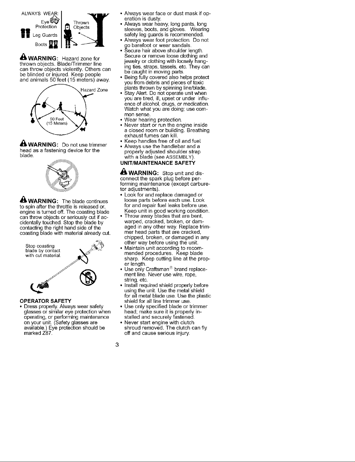
_IbWARNING: Hazard zone for
thrown objects. Blade/Trimmer line
can throw objects violently, Others can
be blinded or injured. Keep people
and animals 50 feet (15 meters) away.
Haza_ Zone
N
_I_WARNING: Do not use trimmer
head as a fastening device for the
blade.
_IbWARNING: The blade continues
to spin after the throttle is released or,
engine is turned off. The coasting blade
can throw objects or seriously cut if ac-
cidentally touched. Stop the blade by
contacting the right hand side of the
coasting blade with material already cut.
Stop coasting
blade by contact
with cut material
®
OPERATOR SAFETY
• Dress properly, Always wear safety
glasses or similar eye protection when
operating, or performing maintenance
on your unit. (Safety glasses are
available.) Eye protection should be
marked Z87.
• Always wear face or dust mask if op-
eration is dusty.
• Always wear heavy, long pants, long
sleeves, boots, and gloves. Wearing
safety leg guards is recommended.
• Always wear foot protectiort Do not
go barefoot or wear sandals.
• Secure hair above shoulder length
Secure or remove loose clothing and
jewelry or clothing with loosely hang-
ing ties, straps, tassels, etc. They can
be caught in moving parts.
• Being fully covered also helps protect
you from debris and pieces of toxic
plants thrown by spinning line/blade.
• Stay Alert. Do not operate unit when
you are tired, ill, upset or under influ-
ence of alcohol, drugs, or medication.
Watch what you are doing; use com-
mon sense.
• Wear hearing protection
• Never start or run the engine inside
a closed room or building. Breathing
exhaust fumes can kill.
• Keep handles free of oil and fuel
• Always use the handlebar and a
properly adjusted shoulder strap
with a blade (see ASSEMBLY).
UNIT/MAINTENANCE SAFETY
_II_WARNING: Stop unit and dis-
connect the spark plug before per-
forming maintenance (except carbure-
tor adjustments).
• Look for and replace damaged or
loose parts before each use. Look
for and repair fuel leaks before use.
Keep unit in good working condition.
• Throw away blades that are bent,
warped, cracked, broken, or dam-
aged in any other way. Replace trim-
mer head parts that are cracked,
chipped, broken, or damaged in any
other way before using the unit.
• Maintain unit according to recom-
mended procedures. Keep blade
sharp. Keep cutting line at the prop-
er length. -_
• Use only Craftsman _ brand replace-
ment line. Never use wire, rope,
string, etc.
• Install required shield properly before
using the unit. Use the metal shield
for all metal blade use. Use the plastic
shield for all line trimmer use.
• Use only specified blade or trimmer
head; make sure it is properly in-
stalled and securely fastened.
• Never start engine with clutch
shroud removed. The clutch can fly
off and cause serious injury.
3

• Be sure blade or trimmer head stops
turning when engine idles.
• Make carburetor adjustments with
the lower end supported to prevent
blade or trimmer line from contacting
any object. Hold unit by hand; do not
use the shoulder strap for support.
• Keep others away when making car-
buretor adjustments.
• Use only recommended Craftsman '_
accessories and replacement parts.
• Have all maintenance and service not
explained in this manual performed by
your Sears Service Center.
FUEL SAFETY
• Mix and pour fuel outdoors
• Keep away from sparks or flame&
• Use a container approved for fuel
• Do not smoke or allow smoking near
fuel or the unit or while using the unit.
• Avoid spilling fuel or oil. Wipe up all
fuel spills before starting engine.
• Move at least 10 feet (3 meters)
away from fueling site before start-
ing engine.
• Stop engine and allow it to cool be-
fore removing fuel cap.
• Empty the fuel tank before storing or
transporting the unit. Use up fuel left
in the carburetor by starting the en-
gine and letting it run until it stops.
• Store unit and fuel in area where fuel
vapors cannot reach sparks or open
flames from water heaters, electric
motors or switches, furnaces, etc.
• Always store gasoline in a container
approved for flammable liquids.
CUTTING SAFETY
_!_WARNING: Inspect the area to
be cut before each use. Remove ob-
jects (rocks, broken glass, nails, wire,
string, etc.) which can be thrown or
become entangled in the blade or
trimmer head.
• Keep others including children, ani-
mals, bystanders, and helpers at least
50 feet (15 meters) away. Stop engine
immediately if you are approached.
• Always keep engine on the right-
hand side of your body.
• Hold the unit firmly with both hands
• Keep firm footing and balance Do
not overreach,
• Keep blade or trimmer head below
waist level. Do not raise engine
above your waist.
• Keep all parts of your body away
from blade, trimmer head, and muf-
fler when engine is running. A hot
muffler can cause serious burns.
• Cut from your left to your right
Cutting on right side of the shield will
throw debris away from the operator.
• Use only in daylight or good artificial
light.
• Use only for jobs explained in this
manual.
TRANSPORTING AND STORAGE
• Stop the unit before carrying
• Keep muffler away from your body
• Allow the engine to cool and secure
the unit before storing or transport-
ing it in a vehicle.
• Empty the fuel tank before storing or
transporting the unit. Use up fuel left
in the carburetor by starting the en-
gine and letting it run until it stops.
• Store unit so the blade or line limiter
blade cannot accidentally cause in-
jury. The unit can be hung by the
tube.
• Store unit out of reach of children
SAFETY NOTICE: Exposure to vibra_
tions through prolonged use of gasoline
powered hand tools could cause blood
vessel or nerve damage in the fingers,
hands, and joints of people prone to cir-
culation disorders or abnormal swell-
ings. Prolonged use in cold weather
has been linked to blood vessel dam-
age in otherwise healthy people. If
symptoms occur such as numbness,
pain, loss of strength, change in skin
color or texture, or loss of feeling in the
fingers, hands, or joints, discontinue the
use of this tool and seek medical atten-
tion, An anti-vibration system does not
guarantee the avoidance of these prob-
lems, Users who operate power tools
on a continual and regular basis must
monitor closely their physical condition
and the condition of this tool.
SPECIAL NOTICE: This unit is
equipped with a temperature limiting
muffler and spark arresting screen
which meets the requirements of Cali-
fornia Codes 4442 and 4443. All U.S.
forest land and the states of California,
Idaho, Maine, Minnesota, New Jersey,
Oregon, and Washington require by law
that many internal combustion engines
be equipped with a spark arresting
screen. If you operate in a locale where
such regulations exist, you are legally
responsible for maintaining the operat-
ing condition of these parts, Failure to
do so is a violation of the law. For nor-
mal homeowner use, the muffler and
spark arresting screen will not require
any service. After 50 hours of use, we
recommend that your muffler be ser-
viced or replaced by your Sears Service
Center.
4

CARTONCONTENTS
Checkcartoncontentsagainstthefol-
lowinglist.
Model358.795200
• Brushcutter
• BladeShieldScrews(4)
• CuppedWasher
• LargeNutforinstallingBlades
• HexWrench
• MetalShield
• PlasticShield
• ShoulderStrapwithWarning
•4-PointWeedBlade
• 8-PointWeedBlade
• TrimmerHead(assembledonunit)
• Handlebar(assembledonunit)
• WingNut(screwedontoshield)
• Containerofline
• Containerofoil
Examinepartsfordamage.Donot
usedamagedparts.
NOTE:Ifyouneedassistanceorfind
partsmissingordamaged_call
1-800-235-5878.
Itisnormalforthefuelfiltertorattlein
theemptyfueltank,
Findingfueloroilresidueonmuffleris
normalduetocarburetoradjustments
and testing done by the manufacturer.
ASSEMBLY
_h, WARNING: Always stop unit
and disconnect spark plug before per-
forming any assembly procedures.
_!i, WARNING: If received as*
sembled, repeat all steps to ensure
your unit is properly assembled and all
fasteners are secure.
TOOLS REQUIRED
• Hex Wrench (provided)
• Adjustable Wrench
ADJUST AND SECURE THE HAN-
DLEBAR
DANGER: To avoid serious inju-
ry, the barrier portion of the handlebar
must be adjusted and remain installed
as shown to provide a barrier between
operator and the spinning blade, The
handlebar clamp must be positioned
between the arrows on the handlebar
decal.
1. Lift handlebar to upright position.
Handlebar
2. Rotate handlebar/clamp counter-
clockwise toward engine until
clamp falls into groove of base.
Clamp
Clarr
Clamp
Base
3. Place the handlebar in a comfort-
able position,
4. Retighten handlebar by turning
clamp knob clockwise until handle-
bar is secure and stationary in
c_amp base (clamp knob can not
be overtightened),
ASSEMBLY OF SHOULDER STRAP
_11_WARNING: Proper shoulder
strap and handlebar adjustments must
be made with the engine completely
stopped before using unit,
1. Insert your right arm and head
through the shoulder strap and al-
low it to rest on your left shoulder.
Make sure the danger sign is on
your back and the hook is to the
right side of your waist.
NOTE: A one*half twist is built in the
shoulder strap to allow the strap to rest
flat on the shoulder,
2. Adjust the strap, allowing the hook
to be about 6 inches below the
waist,
3. Fasten the strap hook to the clamp
located between the trigger handle
and the handlebar clamp base and
lift the tool to the operating position.
4. Try on shoulder strap and adjust
for fit and balance before starting
the engine or beginning a cutting
operation.

NOTE:Itmaybenecessarytorelo-
catetheshoulderstrapclamponthe
shaftforproperbalancingofunit.
TO RELOCATE SHOULDER STRAP
CLAMP:
1. Loosen and remove both clamp
screws.
2. Place the upper shoulder strap
clamp over the tube,
3. Position the lower shoulder strap
clamp under the tube and align the
upper and lower clamp screw
holes.
! Clamp
7
Lower Shoulde !
Strap Clamp
!
30 inches
ASSEMBLY INFORMATION -
TRIMMER HEAD
4. Insert two screws into the screw
holes.
5. Secure shoulder strap clamp by
tightening screws with a hex
wrench.
HARNESS
ADJUSTMENT
FOR BALANCE
6 inches =
be{ow 4 - 12
waist inches
CONFIGURING YOUR UNIT
You can configure your unit using a cut_
ring head for grass and light weeds, or
a weed blade for cutting grass, weeds,
and brush up to 1/2 inch in diameter. To
assemble your unit, go to the section for
the desired configuration and follow the
instructions.
above
.1_'_ round
NOTE: Remove the blade and metal
shield before attaching the plastic shield
and trimmer head, To remove blade,
align hole in the dust cup with the hole
in the side of the gearbox by rotating
the dust cup, Insert a small screwdriv-
er into aligned holes. This will keep
the shaft from turning while loosening
the blade nut, Remove blade nut by
turning clockwise. Remove the screw-
driver, Remove beth washers and
blade, To remove metal shield, loosen
and remove the four mounting screws,
See ATTACHINGTHE METAL SHIELDand
iNSTALLATIONOFTHE METAL BLADE for
illustrations. Be sure to store all parts
and instructions for future use.
INSTALLATION OF THE CUTTING
HEAD (if not already installed)
NOTE: Before installing the trimmer
head, make sure the dust cup and re_
taining washer are positioned on the
shaft of the gearbox. The retaining
washer must be positioned with the
raised section toward the gearbox.
1. Align hole in the dust cup with the
hole in the side of the gearbox by
rotating the dust cup,
2. Insert a small screwdriver into
aligned holes. This will keep the
shaft from turning while tightening
trimmer head.
6

Screwdriver
3. While holding the screwdriver in
position, thread trimmer head onto
the shaft by turning counterclock-
wise. Only tighten hand tight!
Cutting Head
4. Remove the screwdriver.
ATTACHING THE PLASTIC SHIELD
_IbWARNING: The shield must be
properly installed. The shield provides
partial protection from the risk of
thrown objects to the operator and
others and is equipped with a line lim-
iter blade which cuts excess line to the
proper length, The line limiter blade
(on underside of shield) is sharp and
can cut you.
1, Remove wing nut from shield.
2. Insert bracket into slot on shield.
3. Pivot shield until bolt passes
through hole in bracket.
4. Tighten the wing nut securely.
SlotIot__'_--',,._\_Bracket_-_,,,
ShieldSfl-_, .., __N¢,._ WingNut
Retaining
Washer
NOTE: Remove the trimmer head and
plastic shield before attaching the metal
shield and installing one of the weed
blades. To remove the trimmer head,
align hole in the dust cup with the hole
in the side of the gearbox by rotating
the dust cup. Insert a small screwdriver
into aligned holes. This will keep the
shaft from turning while loosening the
trimmer head. Remove the trimmer
head by turning clockwise. Remove the
screwdriver. To remove the plastic
shield, loosen and remove wing nut.
Pivot shield to release bracket from slot.
See INSTALLATIONOF THE CUTTING
HEADand ATTACHINGTHE PLASTIC
SHIELD for illustrations. Be sure to store
all parts and instructions for future use.
Never use the trimmer head with the
metal blade installed.
ATTACHING THE METAL SHIELD
*'I,_
_I_WARNING: The metal shield
must be properly installed on the tool
anytime the tool is used with a blade.
The forward tip of the metal shield
helps to reduce the occurrence of
blade thrust which can cause serious
injury such as amputation to the oper-
ator or bystanders. Failure to install
the shield in the position shown can
result in serious injury to the operator.
The length of the shield must be
aligned with the length of the tube.
1. Place the metal shield under the
gearbox, and align the screw holes.
V _ Gearbox ___
ASSEMBLY INFORMATION - WEED
BLADES
Shield__.. Gearbox
2. Insert and thread the 4 mounting
screws through the holes of the
gearbox and the metal shield.
Tighten evenly and securely with
the hex wrench provided.
INSTALLATION OF THE METAL
BLADE
_11_WARNING: Wear protective
gloves when handling or performing
maintenance on the blade to avoid inju-
ry. The blade is sharp and can cut you
even when it is not moving.
7
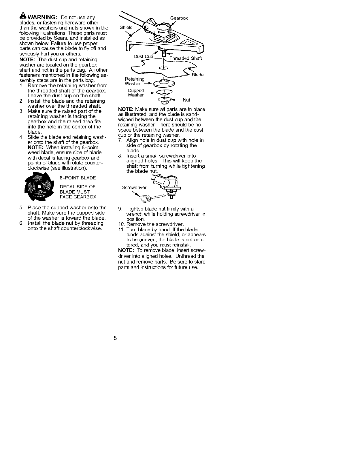
4_IbWARNING: Do not use any
blades, or fastening hardware other
than the washers and nuts shown in the
following illustrations. These parts must
be provided by Sears, and installed as
shown below. Failure to use proper
parts can cause the blade to fly off and
seriously hurt you or others.
NOTE: The dust cup and retaining
washer are located on the gearbox
shaft and not in the parts bag. All other
fasteners mentioned in the following as-
sembly steps are in the parts bag.
1. Remove the retaining washer from
the threaded shaft of the gearbox.
Leave the dust cup on the shaft.
2. Install the blade and the retaining
washer over the threaded shaft.
3. Make sure the raised part of the
retaining washer is facing the
gearbox and the raised area fits
into the hole in the center of the
blade.
4. Slide the blade and retaining wash-
er onto the shaft of the gearbox,
NOTE: When installing 8-point
weed blade, ensure side of blade
with decal is facing gearbox and
points of blade will rotate counter-
clockwise (see illustration).
8-POINT BLADE
DECAL SIDE OF
BLADE MUST
FACE GEARBOX
Gearbox
Shield
Threaded Shaft
Retaining
Washer ---_
Cupped__ ,_
Washer
@-_'_ Nut
NOTE: Make sure all parts are in place
as illustrated, and the blade is sand-
wiched between the dust cup and the
retaining washer. There should be no
space between the blade and the dust
cup or the retaining washer.
7. Align hole in dust cup with hole in
side of gearbox by rotating the
blade.
8. Insert a small screwdriver into
aligned holes. This will keep the
shaft from turning while tightening
the blade nut.
Screwdriver _
5. Place the cupped washer onto the
shaft, Make sure the cupped side
of the washer is toward the blade.
6. Install the blade nut by threading
onto the shaft counterclockwise.
9. Tighten blade nut firmly with a
wrench while holding screwdriver in
position,
10. Remove the screwdriver,
11. Turn blade by hand. If the blade
binds against the shield, or appears
to be uneven, the blade is not cen-
tered, and you must reinstall.
NOTE: To remove blade, insert screw-
driver into aligned holes. Unthread the
nut and remove parts, Be sure to store
parts and instructions for future use.
8

KNOW YOUR BRUSHWACKER
READTHiS INSTRUCTIONMANUALAND SAFETY RULES BEFOREOPERATINGYOUR
UNIT. Compare the illustrationswith your unit to familiarize yourself with the location
of the various controls and adjustments. Save this manual for future reference.
Tnmmer Handlebar
Head
Tube
ON/STOP Switch
Starter Handle
Primer Bulb
Throttle
Trigger
Choke Lever
ON/STOP SWITCH
The ON/STOP switch is used to stop the
engine. To stop the engine, push and
release the engine ON/STOPswitch.
PRIMER BULB
The PRIMER BULB removes air from
the carburetor and fuel lines and fills
them with fuel. This allows you to start
the engine with fewer pulls on the
starter rope. Activate the primer bulb
by pressing it and allowing it to return
to its original form.
BEFORE STARTING ENGINE
_I_WARNING: Be sure to read
the fuel information in the safety rules
before you begin. If you do not under-
stand the safety rules, do not attempt
to fuel your unit. Call 1-800-235-5878.
FUELING ENGINE
_WARNING: Remove fuel cap
slowly when refueling.
This engine is certified to operate on
unleaded gasoline. Before operation,
gasoline must be mixed with a good
quality synthetic 2-cycle air-cooled en-
gine oil. We recommend Craftsman
brand synthetic oil. Mix gasoline and
oil at a ratio of 40:1. A 40:1 ratio is ob-
tained by mixing 3.2 ounces of oil with
1 gallon of unleaded gasoline. In-
cluded with this brushcutter is a 3.2
CHOKE
The CHOKE helps to supply fuel to the
engine to aid in cold starting. Activate
the choke by moving the choke lever to
the FULLCHOKE position. After the em
gine attempts to start, move the choke
lever to the HALF CHOKE position. Once
engine has started, move the choke le-
ver to the OFF CHOKE position.
ounce container of oil. Pour the entire
contents of this container into 1 gallon
of gasoline to achieve the proper fuel
mixture. DO NOT USE automotive oil or
boat oil. These oils will cause engine
damage. When mixing fuel, follow
instructions printed on container.
Once oil is added to gasoline, shake
container momentarily to assure that the
fuel is thoroughly mixed. Always read
and follow the safety rules relating to
fuel before fueling your unit.
IMPORTANT
Experience indicates that alcohol
blended fuels (called gasohol or using
ethanol or methanol) can attract mois-
ture which leads to separation and
formation of acids during storage.
Acidic gas can damage the fuel sys-
tem of an engine while in storage.
9

To avoid engine problems, empty the
fuel system before storage for 30 days
or longer. Drain the gas tank, start the
engine and let it run until the fuel lines
and carburetor are empty. Use fresh
fuel next season.
Never use engine or carburetor clean-
er products in the fuel tank or perma-
nent damage may occur.
See the STORAGE section for addition-
al information.
HOW TO STOP YOUR UNIT
• To stop the engine, push and re-
lease the engine ON/STOP switch.
The switch will automatically return
to the ON position. Wait 5 seconds
before attempting to restart unit to
allow switch to reset,
• If engine does net stop, move choke
lever to FULL CHOKE position.
_I_ ON/STOP
Choke
position
decal
4. Squeeze the throttle trigger fully and
hold through all remaining steps.
5. Pull starter rope handle sharply
until engine sounds as if it is trying
to start, but do not pull rope more
than 6 times.
6. As soon as engine sounds as if it
is trying to start, move choke lever
to HALF CHOKE by aligning lever
with position shown on decal (see
illustration below).
Throttle Trigger _
HOW TO START YOUR UNIT
_b_WARNING: The trimmer head
will turn while starting the engine.
Avoid any contact with the muffler. A
hot muffler can cause serious burns.
STARTING A COLD ENGINE (or a
warm engine after running out of
fuel)
g Position
Handle
Choke
.Lever
Primer Bulb
Muffler
1, Set unit on a flat surface,
2. Slowly press the primer bulb 6
times,
3. Move choke lever to FULL CHOKE
by aligning lever with position
shown on decal (see illustration
below).
Choke
position
7. Pull starter rope sharply until engine
runs, but no more than 6 pulls. If the
engine doesn't start after 6 pulls (at
the HALFCHOKE position), move the
choke lever to the FULL CHOKE
position and press the primer bulb 6
times. Squeeze and hold the throttle
trigger and pull the starter rope 2
more times. Move the choke lever
to the HALF CHOKE position and pull
the starter rope until the engine
runs, but no more than 6 pulls. If the
engine doesn't start, repeat proce-
dure 2 additional times.
NOTE: If engine still doesn't start, it
is probably flooded. Proceed to
STARTINGA FLOODED ENGINE.
8. Once the engine starts, allow itto
run 10 seconds, then move the
choke lever to OFF CHOKE by align-
ing lever with position shown on de-
cal (see illustration below). Allow the
unit to run for 30 more seconds at
OFF CHOKEbefore releasing the
throttle trigger. NOTE: If engine dies
with the choke lever in the OFF
CHOKEposition, move the choke le-
ver to the HALFCHOKE position and
pull the rope until engine runs, but
no more than 6 pulls.
10

Choke
position
STARTING A WARM ENGINE
1. Move the choke lever to the HALF
CHOKE position.
2. Squeeze and hold the throttle trig-
ger. Keep throttle trigger fully
squeezed until the engine runs
smoothly.
3. Pull starter rope sharply until engine
runs, but no more than 5 pulls.
4. Allow engine to run 15 seconds,
then move the choke lever to the
OFF CHOKE position.
NOTE: If engine has net started, pull
starter rope 5 more pulls. If engine still
does net run, it is probably flooded.
STARTING A FLOODED ENGINE
Flooded engines can be started by
placing the choke lever in the OFF
CHOKE position; then, pull the rope to
clear the engine of excess fuel. This
could require pulling the starter handle
many times depending on hew badly
the unit is flooded. If the unit still
doesn't start, refer to TROUBLESHOOT-
ING TABLE or call 1-800-235-5878.
OPERATING POSITION
ALWAYSWEAR:
E e Protection
Long P___
B°°ts"_ _ _1 _ft_ _
Cut only from your e t to your rig t.
When operating unit, clip shoulder
strap onto clamp, stand as shown and
check for the following:
• Wear eye protection and heavy
clothing.
• Extend your left arm and held han-
dlebar grip with your left hand.
• Hold throttle grip with your right hand
with finger on throttle trigger.
• Keep unit below waist level.
• Keep shoulder strap pad centered
on your left shoulder and danger
sign centered on your back.
• Maintain full weight of tool on your
left shoulder.
• Cut only from your left to your right to
ensure debris is thrown away from
you. Without bending over, keepthe
blade or trimmer head near and par-
allel to the ground and not crowded
into material being cut.
OPERATING INSTRUCTIONS FOR
USE WITH TRIMMER HEAD
_h, WARNING: Always wear eye
protection. Never lean over the trimmer
head. Rocks or debris can ricochet or
be thrown into eyes and face and
cause blindness or other serious injury.
Before trimming, bring engine to a
speed sufficient to cut material to be
trimmed.
Do not run the engine at a higher speed
than necessary. The cutting line will cut
efficiently when the engine is run at less
than full throttle. At lower speeds, there
is less engine noise and vibration. The
cutting line will last longer and will be
less likely to "weld" onto the spool.
Always release the throttle trigger and
allow the engine to return to idle
speed when not cutting.
To stop engine:
• Release the throttle trigger.
• Push and release the engine ON/
STOP switch.
_JkWARNING: Use minimum
speed and de not crowd the line when
cutting around hard objects (rock,
gravel, fence posts, etc.), which can
damage the trimmer head, become
entangled in the line, or be thrown
causing a serious hazard.
• The tip of the line does the cutting.
You will achieve the best perform-
ance and minimum line wear by net
crowding the line into the cutting
area. The right and wrong ways are
shown below.
Tip of line does the
Right Wrong
Line crowded into
work area
11

• The line will easily remove grass
and weeds from around walls,
fences, trees and flower beds, but it
also can cut the tender bark of trees
or shrubs and scar fences.
• For trimming or scalping, use less
than full throttle to increase line life
and decrease head wear, especially:
• During light duty cutting.
• Near objects around which the line
can wrap such as small posts,
trees or fence wire.
• For mowing or sweeping, use full
throttle for a good clean job.
TRIMMING - Hold the bottom of the
trimmer head about 3 in. (8 cm) above
the ground and at an angle. Allow only
the tip of the line to make contact. Do
not force trimmer line into work area.
Trimming
SCALPING - The scalping technique
removes unwanted vegetation down to
the ground. Hold the bottom of the trim-
mer head about 3 in. (8 cm) above the
ground and at an angle. Allow the tip of
the line to strike the ground around
trees, posts, monuments, etc. This tech-
nique increases line wear.
Scalping
MOWING - Your trimmer is ideal for
mowing in places conventional lawn
mowers cannot reach. In the mowing
position, keep the line parallel to the
ground. Avoid pressing the head into
the ground as this can scalp the
ground and damage the tool.
Mowing
SWEEPING - The fanning action of the
rotating line can be used to blow away
loose debris from an area. Keep the line
parallel to and above the area surface
and swing the tool from side to side.
Sweeping
OPERATING INSTRUCTIONS FOR
USE WITH WEED BLADES
• Blade Thrust is a reaction that only
occurs when using a bladed unit. This
reaction can cause serious injury
such as amputation. Carefully study
this section, It is important that you
understand what causes blade thrust,
how you can reduce the chance of its
occurring, and how you can remain in
control of unit if blade thrust occurs.
• WHAT CAUSES BLADE THRUST -
Blade Thrust can occur when the
spinning blade contacts an object that
it does not cut. This contact causes
the blade to stop for an instant and
then suddenly move or "thrust" away
from the object that was hit. The
"thrusting" reaction can be violent
enough to cause the operator to be
propelled in any direction and lose
control of the unit. The uncontrolled
unit can cause serious injury if the
blade contacts the operator or others.
• WHEN BLADE THRUST OCCURS
- Blade Thrust can occur without
warning if the blade snags, stalls, or
binds. This is more likely to occur in
areas where it is difficult to see the
material being cut. By using the unit
properly, the occurrence of blade
thrust will be reduced and the opera-
tor will be less likely to lose control.
12
 Loading...