

Craftsman 358795050 Owner’s Manual

Operator's Manual
®
CRRFTZMRN
32cc 2-Cycle Engine
17 Inch Cutting Path / .080 In. Line
GASOLINE BRUSHWACKER ®
Model No.
358.795050
Read and follow all Safety Rules and Operating
DANGER:
Instructions before first use of this product.
I_ For answers to Your questions about this product:
Call 7 am-7 pm, Mon--Sat; Sun, 10 am-7 pm
• 1-800-235-5878 (.o,,_.,,=._._o.._.)
Se_IYs,Roebuck and Co., Hoffman Estates, IL 60179 USA
530-087633 08/17/98
Warranty Statement 2 Storage 15
Safety Rules 2 Troubleshooting Chart 16
Assembly _ ..... 5 Parts List 20
Operation 8
Maintenance 12 Spanish 23
Sewice & Adjustments 13 Parts and Ordering Back
FULL ONE YEAR WARRANTY ON CRAFTSMAN GAS POWERED
BRUSHWACKER ® BLADED TRIMMER.
For oneyear from the date of purchase, when thisCraftsman Gas Powered
Brushwackeris maintained, lubricatedand tuned upaccordingto the operating
and maintenance instructionsinthe Operator's Manual, Sears will repair,free of
charge, any defect in materials or workmanship.
This warranty excludes the blade, nylonline, sparkplug,and airfilter, which are
expendable parts and become wom duringnormaluse.
Ifthis Brushwacker is used forcommercial purposes,thiswarranty appliesfor only
90 daysfrom the date of purchase. IfthisBrushwackeris usedfor rentalpurposes,
this warranty applies for only30 days from the date ofpurchase. Thiswarranty ap-
plies onlywhile this product is in use inthe United States.
WARRANTY SERVICE IS AVAILABLE BY RETURNING THE BRUSHWACKER
TO THE NEAREST SEARS SERVICE CENTER IN THE UNITED STATES.
This warranty gives you specificlegal rights,and you may also have other rights
whichvary from state to state.
Sears, Roebuck and Co., D/817 WA Hoffman Estates, IL 60179
DANGER: This power tool can be
dangerous!This unitcan cause serious
injuryincludingamputationor blindness
to the operatorand others.The warn-
ingsand safety instructionsin thisman-
ual mustbe followedto providemason-
able safety and efficiencyin usingthe
unit.3"beeperator is responsiblefor fol-
lowingthe wamings and instructionsin
this manualand on the unit.Read the
entireOperator'sManual beforeassern-
blingand usingthe unit!Restricttheuse
of this unitto personswho read, under-
stand,and followthe warningsand in-
structions in thismanual and on the unit.
Never allowchildrento usethis uniL
WARNII_G: Follow all wamings and
instructions. Failure to do so can result
in sedous injury.
SAFETY NOTICE
Exposure to vibrations through pro-
longed use of gasoline powered hand
tools could cause blood vessel or
nerve damage in the fingers, hands,
and joints of people prone to circula-
tion disorders or abnormal swellings.
Prolonged use in cold weather has
been linked to blood vessel damage in
otherwise healthy people. If symptoms
occur such as numbness, pain, lose of
strength, change in skin color or tex-
ture, or loss of feeling in the fingers,
hands or joints, discontinue the use of
this tool and seek medical attention.
An anti-vibration system does not
guarantee the avoidance of these
problems. Users who operate power
tools on a continual and regular basis
must monitor closely their physical
condition and the condition of this tool.
2
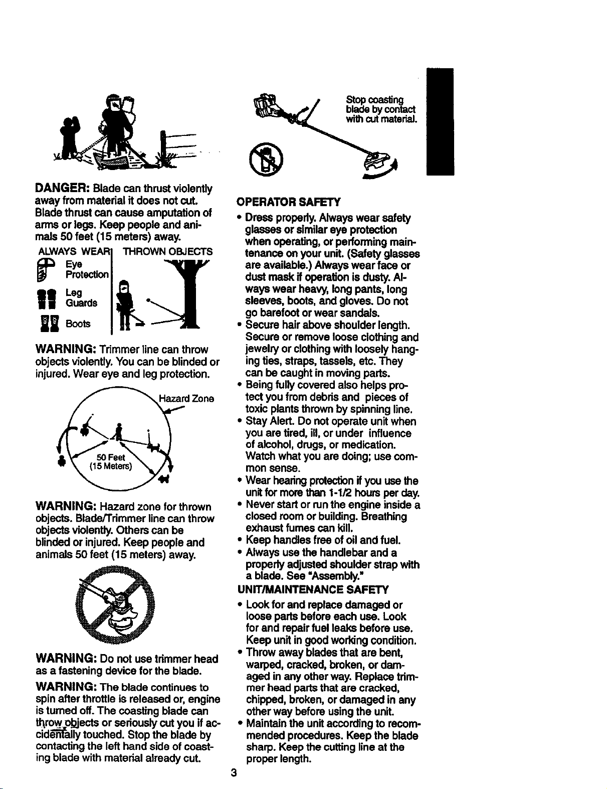
DANGER: Bladecanthrustviolently
awayfrommaterialit doesnotcut.
Bladethrustcancause amputation of
arms or legs. Keep people and ani-
mals 50 feet (15 meters) away.
ALWAYS WEAR
I
Guards I •
Leg J
U BootaI
WARNING: Trimmer line can throw
objects violently. You can be blinded or
injured. Wear eye and leg protection.
HazardZone
WARNING: Hazard zone for thrown
objects. Blade/Trimmer line can throw
objects violently. Others can be
blinded or injured. Keep people and
animals 50 feet (15 meters) away.
WARNING: Do not use trimmer head
as a fastening device for the blade.
WARNING: The blade continues to
spin after throttle is released or, engine
is turned off. The coasting blade can
throw obiects or seriously cut you if ac-
ciden-fft-allytouched. Stop the blade by
contacting the left hand side of coast-
ing blade with material already cut.
tiSt_ coas_ng
• bycontact
with cutmaterial
®
OPERATOR SAFETY
• Dress properly. Always wear safety
glasses or similar eye protection
when operating, or performing main-
tenance on your unR. (Safety glasses
are available.) Always wear face or
dust mask if operation is dusty. Al-
ways wear heavy, long pants, long
sleeves, boots, and gloves. Do not
go barefoot or wear sanda/s.
• Secure hair above shoulder length.
Secure or remove loose clothing and
jewelry or clothing with loosely hang-
ing ties, straps, tassels, etc. They
can be caught in moving parts.
• Being fully covered also helps pro-
tect you from debris and pieces of
toxic plants thrown by spinning line.
• Stay Alert. Do not operate unit when
you are tired, ill, or under influence
of alcohol, drugs, or medication.
Watch what you are doing; usa com-
mon sense.
• Wear hearing protection if you use the
unitfor more than 1-1/2 hours per day.
• Never start or run the engine inside a
closed room or building. Breathing
exhaust fumes can kill.
• Keep handles free of oil and fuel.
• Always usa the handlebar and a
properly adjusted shoulder strap with
a blade. See "Assembly."
UNIT/MAINTENANCE SAFETY
• Look for and replace damaged or
loose parts before each usa. Look
for and repair fuel leaks before usa.
Keep unit in good working condition.
• Throw away blades that are bent,
warped, cracked, broken, or dam-
aged in any other way. Replace trim-
mer head parts that are cracked,
chipped, broken, or damaged in any
other way before using the unit.
• Maintain the unit according to recom-
mended procedures. Keep the blade
sharp. Keep the cutting line at the
proper length.
3
• Use only .080" (2.4 ram) diameter
Craftsman © brand line. Never use
wire, rope, stdng, etc.
• Install required shield properly before
using the uniL Use the metal shield
for all metal blade use. Usethe plas-
tic shield for all line trimmer-use.
- • Use only specified blade or tdmmer
head; make sure it is properly in-
stalled and securely fastened,
* Never start engine with clutch shroud
removed. The clutch can fly off and
cause serious injury.
• Be sure blade or tdmmer head stops
turning when engine idles,
• Disconnect the spark plug before
performing maintenance (except car-
buretor adjustments).
• Make carburetor adjustments with
the lower end supported to prevent
the blade or trimmer line from con-
tacting any object. Hold the unit by
hand; do not use the shoulder strap
for support.
• Keep others away when making car-
buretor adjustments.
• Use only recommended Craftsman
accessories and replacement parts.
• Have all maintenance and service
not explained in this manual per-
formed by a Sears Service_Center.
FUEL SAFETY
• Mix and pour fuel outdoors.
• Keep away from sparks or flames.
• Use a container approved for fuel.
• Do not smoke or allow smoking near
fuel or the unit or while using the unit.
• Wipe up all fuel spills before starting
engine.
• Moye,r_at-least 10 feet (3 meters) away
from fueling site before starling engine.
• Stop engine and allow-it to-cool be-
fore removing fuel cap.
• Empty the fuel tank before storing
the unit. Use up fuel left in the carbu-
retor by starting the engine and let-
ting it run until it stops.
• Storeunitandfuelin an area where
fuel vaporscannotreachsparksor
openflames from water heaters,elec-
tricmotorsor switches,furnaces, etc.
CUTTING SAFETY
• Inspectthe area to be cut before
each use. Remove objects(rocks,
brokenglass, nails,wire, string, etc.)
whichcan be thrown or become en-
tangled inthe blade or trimmer head.
• Keep othersincludingchildren,ani-
mals, bystanders,and helpersat
least 50 feet (15 meters) away. Stop
the engine immediatelyif you are ap-
proached.
• Always keep engine onthe right-
hand side of yourbody.
• Hold the unitfirmlywithboth hands.
• Keep firmfootingand balance.Do
notoverreach.
• Keep blade ortrimmer head below
waist level.
• Do notraise engineaboveyourwaist.
• Keep all pads ofyour body away
from blade,trimmer head, and muf-
flerwhen engine is running.
• Cut fromyour righttoyour left.
• Use onlyforjobs explainedin this
manual.
TRANSPORTING AND STORAGE
• Stopthe unitbefore carrying.
• Keep muffleraway from yourbody.
• Allowengine to cool and secure unit
before storing ortransportingit in a
vehicle.
• Emptythe fuel tank before storingor
transportingthe unit. Use upfuel left
in the carburetor by startingthe en-
gine and lettingit run untilitstops.
• Store unitand fuel inan area where
fuel vapors cannot roachsparks or
open flamesfrom water heaters,
electdcmotors orswitches,fumaces,
etc.
• Store unitsothe blade or line limiter
cannot accidentallycause injury.The
unitcan be hung bythe tube.
• Store unitout ofreach of children.
4
CARTON CONTENTS
Check carton contents against the fol-
lowing list. _ .....
Model: 358,795050
• Brushcutter
• Handlebar screws (2)
• Blade shield screws (4)
• Cupped washer
• Large nut for installing blade
• Long hex wrench
• Short hex wrench
• Bracket cover
• Metal shield
• Plastic shield
• Shoulder strap with waming
• Weed blade
• Trimmer head
• Handlebar
• Container of oil
Examine parts for damage. Do not use
damaged parts.
NOTE: If you need assistance or find
that parts are missing or damaged, call
1-800-235-5878,
Itis normal for the fuel filter to rattle in the
empty fuel tank.
Finding fuel or oil residue on muffler is
normal due to carburetor adjustments
and testing done by the manufacturer.
ASSEMBLY
WARNING: If received assembled, re-
_.atatatata_allstepsto ensure your unitisproper-
mbled and allfastenem are secure.
TOOLS REQUIRED
adjustable wrench or large pliers
2 hex wrenches (provided)
phmips screwdriver
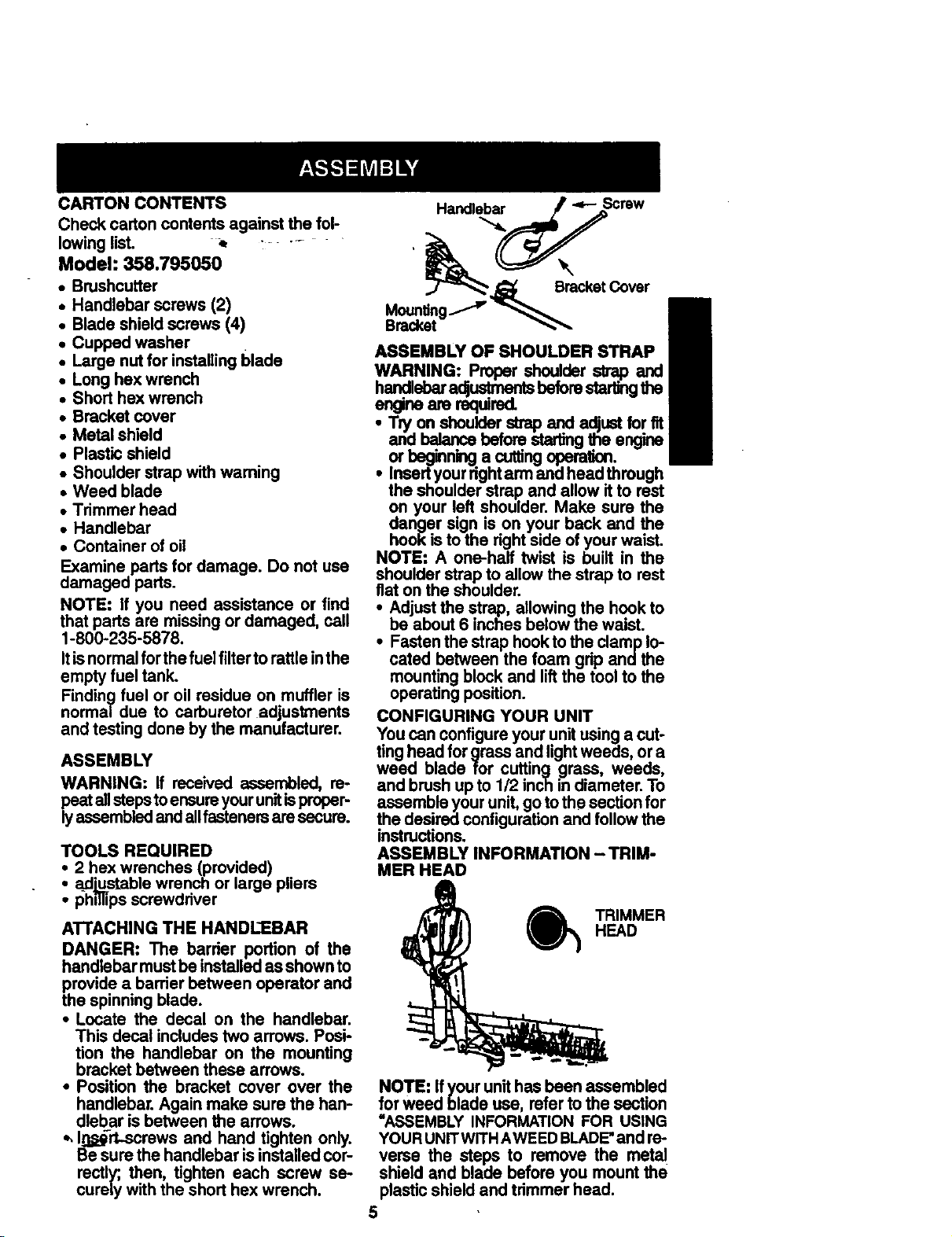
ATTACHING THE HANDLEBAR
DANGER: The barrier portion of the
handlebar must be installed as shown to
provide a barrier between operator and
the spinning blade.
• Locate the decal on the handlebar.
This decal includes two arrows. Posi-
tion the handlebar on the mounting
bracket between these arrows.
• Position the bracket cover over the
handlebar. Again make sure the han-
dlebar is between the arrows.
*, I_,_rt-screws and hand tighten only.
Be sure the handlebar is installed cor-
rectly; then, tighten each screw se-
curely with the short hex wrench.
ASSEMBLY OF SHOULDER STRAP
WARNING:
engineare required.
• Insert'
the
on your left Make sure the
danger sign is on your back and the
hook is to the right side of your waist.
NOTE: A one-half twist is built in the
shoulder strap to allow the strap to rest
flat on the shoulder.
• Adjust the strap, allowing the hook to
be about 6 inches below the waist.
• Fasten the strap hook to the clamp lo-
cated between the foam grip and the
mounting block and lift the tool to the
operating position.
CONFIGURING YOUR UNIT
You can configure your unit using a cut-
ting head for grass and light weeds, or a
weed blade for cutting grass, weeds,
and brush up to 1/2 inch in diameter. To
assemble your unit, go to the section for
the desired configuration and follow the
instructions.
ASSEMBLY INFORMATION - TRIM-
MER HEAD
HEAD
) TRIMMER
NOTE: Ifyourunithasbeen assembled
forweed blade use, refer to the section
=ASSEMBLY INFORMATIONFOR USING
YOURUNITWITHAWEEDBLADE"and re-
verse the steps to remove the metal
shield and blade before you mountthe
plasticshieldand trimmer head.
5
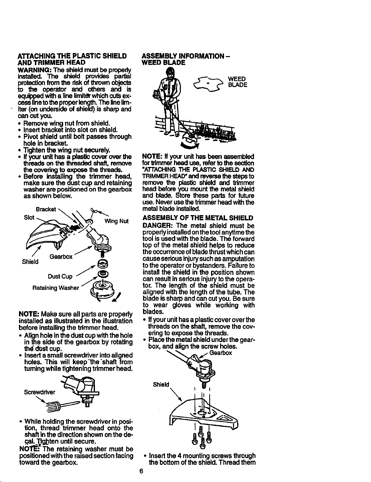
ATTACHINGTHEPLASTICSHIELD
ANDTRIMMERHEAD
WARNING:Theshieldmustbeproperly
installed.The shield providespartial
pmtsctionfromtheriskofthrown objects
to _ operator and others and is
equil_3edwitha linelirnltdrwhichct_sex-
casslinetotheproper length.The linelim-
- iter(on undersideof shield)is sharp and
cancut you.
Remove wing nut from shield.
Insertbracket intoslot on shield.
• Pivot shield untilbolt passes through
hole in bracket.
Tightenthe wing nut securely.
Ifyourunithas a plasticcoverover the
threads on the threaded shaft,remove
the covetingto exposethethreads.
• Before installing the trimmer head,
make sure the dustcup and retaining
washer are positionedonthe gearbox
as shown below.
Bracket _ . c__
RotainiDnU_er / _
NOTE: Make sure allparts are propedy
installed as illustratedin the illustration
before installingthe trimmer head.
• Alignholeinthe dustcupwiththe hole
inthe side of the gearbox by rotating
thd _st cup.
• Inserta smallscrewdriverintoaligned
holes. Th_ will keep-the'shaft from
tumingwholetighteningtrimmerhead.
ASSEMBLY INFORMATION -
WEED BLADE
BLADE
WEED
NOTE: If your unit has been assembled
for _mmer head use, refer to the section
"ATTACHINGTHE PLASTIC SHIELD AND
TRIMMER HEAD"and reverse the steps to
remove the plastic shield and trimmer
head before you mount the metal shield
and blade. Store these pads for future
use. Never use the trimmer head with the
metal blade installed.
ASSEMBLY OF THE METAL SHIELD
DANGER: The metal shield must be
properiyinstalled on the tool anytime the
tool is used with the blade. The forward
top of the metal shield helps to reduce
the occurrence ofblade thrust which can
cause serious injury such as amputation
to the operator or bystanders. Failure to
install the shield in the position shown
can result in serious injury to the opera-
tor. The length of the shield must be
aligned with the length of the tube. The
blade is sharp and can cut you. Be sure
to wear gloves while working with
blades.
• Ifyour unit has a plastic cover over the
threads on the shaft, remove the cov-
ering to expose the threads.
• Place the metal shield under the gear-
box, and align the screw holes.
Shield_J, Gearb°x
Screwdriver
• While holdingthe screwdriver in posi-
tion, thread trimmer head onto the
shaft inthe directionshownonthe de-
.qal_T_jbtenuntilsecure.
NOTE:The ratainin(j washer must be
positionedwiththe ra0sedsectionfacing
toward the gearbox.
• Insertthe 4 mountingscrewsthrough
the bottomofthe shield.Thread them
6
into the gearbox. Tighten evenly and
securely with one of the hex wrenches
provided.
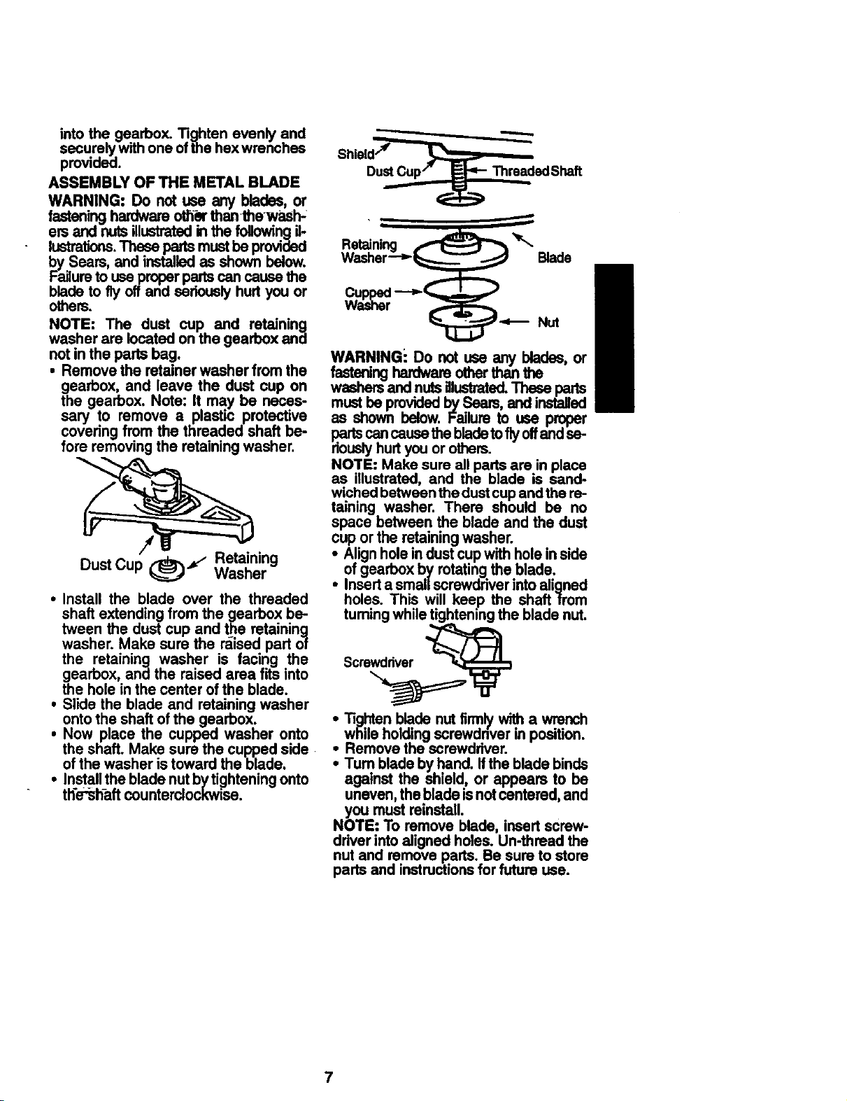
ASSEMBLY OF THE METAL BLADE
WARNING: Do not use any blades, or
fasteninghardwareoffie"thanthewash-
ers and nutsillustratedinthe followingil.
lustrations.These partsmustbe provided
by Sears, and installedas shown below.
Failuretouse properpartscancausethe
bladeto fly offand seriouslyhurtyou or
others.
NOTE: The dust cup and retaining
washer are located on the gearbox and
notin the parts bag.
• Remove the retainerwasher from the
gearbox, and leave the dust cup on
the gearbox. Note: It may be neces-
sary to remove a plastic protective
covering from the threaded shaft be-
fore removingthe retainingwasher.
Shield''_
DustCup/" _ ThreadedShaft
m
Retaining _ _'_
Washer--__ Blade
WARNINGi Do not use any blades, or
fasteninghardwareotherthanthe
washersand nutsillustrated.These parts
mustbe providedbySeam, andinstalled
as shown below. Failureto use proper
partscancause thebladetotiyoffandse-
riouslyhurtyouorothers.
NOTE: Make sure allparts are inplace
as illustrated, and the blade is sand-
wichedbetweenthedustcupandthere-
taining washer. There should be no
space between the blade and the dust
cup or the retainingwasher.
Dust Cup (_='_ WasherRetaining
• Install the blade over the threaded
shaft extendingfrom the gearbox be-
tween the dust cup and the retaining
washer. Make sure the raised part of
the retaining washer is facing the
gearbox, and the raised area fits into
the hole in the center ofthe blade.
• Slide the blade and retaining washer
ontothe shaft ofthe gearbox.
• Now place the cupped washer onto
the shaft. Make sure the cupped side
ofthe washer is toward the blade.
• Installthe blade nutb_/ti_ghteningonto
th'e'_haftcounterolockwJse.
of gearbox byrotatingthe blade.
i Alignholein dustcupwithholeinside
Inserta smallscrewdriverintoaligned
holes. This will keep the shaftfrom
tumingwhile tighteningthe blade nut.
Scre__
Tightenblade nutfirmlywitha wrench
i while holding position.
Remove the screwdriver.
screwdnverin
• Turn blade by hand. Ifthe blade binds
against the shield, or appears to be
uneven,the blade isnotcentered,and
you must reinstall.
NOTE: To remove blade, insertscrew-
ddver intoaligned holes. Un-threadthe
nut and remove parts. Be sureto store
partsand instructionsforfuture use.
7
 Loading...