

Craftsman 358794250 Owner’s Manual

Operator's Manual
25cc/1.5 cu.in. 2-Cycle
17 Inch Cutting Path / 0.080 In. Line
GASOLINE WEEDWACKER ®
Model No.
358.794250
For Occasional Use Only
Read and follow all Safety Rules and Operating
WARNING:
Instructions before first use of this product.
For answers to your questions about this product:
Call 7 am-7 pm, Mon.-Sat., or 10 am-7 pm, Sun.
®
• 1-800-235-5878 !.ou_ listed are Central'13me)
Sears, Roebuck and Co., Hoffman Estates, IL 60179 U.S.A.
530086204 4/9/01
10
2
2
4
5
9
Storage 11
Troubleshooting Chart 12
Emissions Statement 13
Parts List 15
Spanish 18
Parts and Ordering BackCover
Warranty Statement
Safety Rules
Assembly
Operation
Maintenance
Service & Adjustments
FULL ONE YEAB.WARRANTY ON
WEEDWACKER _ LINE TRIMMER
For one year from the date of purchase, when this Craftsman Gas Powered
Weedwacker Line Trimmer is maintained, lubricated, and tuned up according to
the operating and maintenance instructions in the Operator's Manual Sears will
repair, free of charge, any defect in materials or workmanship.
This warranty excludes nylon line, spark plug, and air filter, which are expendable
parts and become worn during normal use.
If this Weedwacker line trimmer is used for commercial purposes, this warranty ap-
plies for only 90 days from the date of purchase. If this Weedwacker line trimmer is
used for rental purposes, this warranty applies for only 30 days from the date of pur-
chase. This warranty applies only while this product is in use inthe United States.
WARRANTY SERVICE IS AVAILABLEBY RETURNING THE WEEDWACKER LINE TRIMMER
TO THE NEAREST SEARS STORE OR SERVICE CENTER IN THE UNITED STATES.
This warranty gives you specific legal rights, and you may also have other rights
which vary from state to state.
Sears, Roebuck and Co., 1:)/817 WA, Hoffman Estates, IL 60179
_kWARNING: When using gar-
dening appliances, basic safety pre-
cautions must always be followed to
reduce the risk of fire and serious
injury. Read and follow all instructions.
This power unit can be dangerous! Op-
erator is responsible for following
instructions and warnings on unit and in
manual. Read entire Operator's Manual
before using unit! Be thoroughly familiar
with the controls and the proper use of
the unit. Restrict the use of this unit to
persons who have read, understand,
and will follow the instructions and
warnings on the unit and in the manual.
Never allow children to operate this unit.
OPERATORS
MANUAL
_k, DANGER: Never use blades or
flailing devices. This unit is designed
for line trimmer use only. Use of any
SAFETY INFORMATION
ON THE UNIT
other accessories or attachments will
increase the risk of injury.
@@@
_WARNING: Trimmer line throws
objects violently. You and others can be
blinded/injured. Wear eye and leg
protection. Keep body parts clear of ro-
tating line.
Eye Protection
_ Hazard Zone
Keep children, bystanders, and animals
50 feet (15 meters) away. Stop unit im-
mediately if approached.
if situations occur which are not cov-
ered in this manual, use care and
good judgment. If you need assis-
tance, contact your Sears Service
Center or call 1-800-235-5878.
2
6
OPERATOR SAFETY
• Dress properly. Always wear safety
glasses or similar eye protection
when operating, or performing main-
tenance on your unit (safety
glasses are available). Eye protec-
tion should be marked ANSI Z87.
• Always wear face or dust mask ifop-
• eration is dusty.
Always wear heavy.,long pants, long
sleeves, boots, and gloves. Wear-
_ngsafety leg guards is recom-
mended.
• Always wear foot protection. Do not
go barefoot or wear sandals. Stay
clear of spinning line.
• Secure hair above shoulder length.
Secure or remove loose clothing or
clothing with loosely hanging ties,
straps, tassels, etc. They can be
caught in moving pads.
• Being fully covered also helps pro-
tect you from debris and pieces of
• toxic plants thrown by spinning line.
Stay Alert. Do not operate this unit
when you are tired, ill, upset or un-
der the influence of alcohol, drugs,
or medication. Watch what you are
doing; use common sense.
• Wear hearing protection.
• Never start or run inside a closed
room or building. Breathing exhaust
fumes can kill.
• Keep handles free of oil and fuel.
UNIT / MAINTENANCE SAFETY
• Disconnect the spark plug before
performing maintenance except car-
buretor adjustments.
• Look for and replace damaged or
loose parts before each use. Look
for and repair fuel leaks before use.
Keep in good working condition.
• Replace trimmer head parts that are
chipped, cracked, broken, or dam-
aged in any other way before using
the unit.
• Maintain unit according to recom-
mended procedures. Keep cutting
line at proper length.
• • Use only 0.080 in.(2 mm) diameter
Craftsman® brand line. Never use
wire, rope, string, etc.
• Install required shield properly be-
fore using the unit. Use only speci-
fied trimmer head; make sure it is
properly installed and securely fas-
tened.
• Make sure unit is assembled cor-
rectly as shown in this manual.
• Make carburetor adjustments with
lower end supported to prevent line
from contacting any object.
• Keep others away when making car-
buretor adjustments.
• Use only recommended Craftsman
accessories and replacement pads.
• Have all maintenance and service
not explained in this manual per-
formed by a Sears Service Center.
FUEL SAFETY
• Mix and pour fuel outdoors.
• Keep away fromsparks or flames.
• Use a container approved for fuel.
• Do notsmoke or allow smokingnear
fuel orthe unit.
• Avoid spilling fuel or oil. Wipe up all
fuel splits.
• Move at least 10 feet (3 meters)
away from fueling site before start-
mg engine.
• Stop engine and allow to cool before
removing fuel cap.
• Always store gasoline ina container
approved for flammable liquids.
CU'R'ING SAFETY
_'WARNING: Inspect the area be-
fore each use. Remove objects
(rocks, broken glass, nails, wire, etc.)
which can be thrown by or become
entangled in line. Hard objects can
damage the trimmer head and be
thrown causing serious injury.
• Use only for trimming, scalping mow-
ng and sweeping. Do not use for edg-
ing, pruning or hedge trimming.
• Keep firm footing and balance. Do
not overreach.
• Keep all parts of your body away
from muffler and spinning line. Keep
engine below waist level. A hot muf-
fler can cause serious bums.
• Cut from your right to your left. Cut-
ting on left side of the shield will
throw debris away from the operator.
• Use only in daylight or good artificial
light.
• Use only for joos explained in this
manual.
TRANSPORTING AND STORAGE
• Allow engine to cool; secure unit be-
fore storing or transporting in ve-
hicle.
• Empty the fuel tank before storing or
transporting the unit. Use up fuel left
in the carburetor by starling, the en-
gine and letting it run until =tstops.
• Store unit and fuel in area where
fuel vapors cannot reach sparks or
open flames from water heaters,
electric motors or switches, fur-
naces, etc.
3
• Store unit so line limiter blade can-
not accidentally cause injury. The
unit can be hung by the tube.
• Store unit out of reach of children.
SAFETY NOTICE: Exposure to vibra-
tions through prolonged use of gaso-
line powered hand tools could cause
blood vessel or nerve damage in the
fingers, hands, and joints of people
prone to circulation disorders or ab-
normal swellings. Prolonged usa in
cold weather has been linked to blood
vessel damage in otherwise healthy
people. If symptoms occur such as
numbness, pain, loss of strength,
change in skin color or texture, or loss
of feeling in the fingers, hands, or
joints, discontinue the usa of this tool
and seek medical attention. An anti-
vibration system does not guarantee -
the avoidance of these problems. Us-
ers who operate power tools on a con-
tinual and regular basis must monitor
closely their physical condition and
the condition of this tool.
SPECIAL NOTICE: This unit is
equipped with a temperature limiting
muffler and spark arresting screen
which meets the requirements of Calf
fomia Codes 4442 and 4443. All U.S.
forest land and the states of California,
Idaho, Maine, Minnesota, New Jersey,
Oregon, and Washington require by
law that many intemal combustion en-
gines be equipped with a sparkarrest-
g screen. If you operate in a locale
where such regulations exist, you are
legally responsible for maintaining the
operating condition of these parts. *.
Failure to do so is a violation of the
law. For normal homeowner use, the
muffler and spark arresting screen will
not require any service. After 50
hours of use, we recommend that your
muffler be serviced or replaced by
your Sears Service Center.
CARTON CONTENTS
Check carton contents against the fol-
lowing list.
Model 358.794250
• Trimmer
• Shield
• Wing Nut (screwed onto shield)
Assist Handle (with bolt and knob)
• Container of Oil
• Replacement Spool
Examine parts for damage. Do not
use damaged parts.
NOTE: If you need assistance or find
parts missing or damaged, call
1°800-235-5878.
It is normal for the fuel filter to rattle in
the empty fuel tank.
Finding fuel or oil residue on muffler is
normal due to carburetor adjustments
and testing done by the manufacturer.
ASSEMBLY
,_LWARNING: If received as-
sembled, repeat all steps to ensure
your unit is properly assembled and all
fasteners are secure.
Be sure to attach the assist handle to
the unit before you attach the shield.
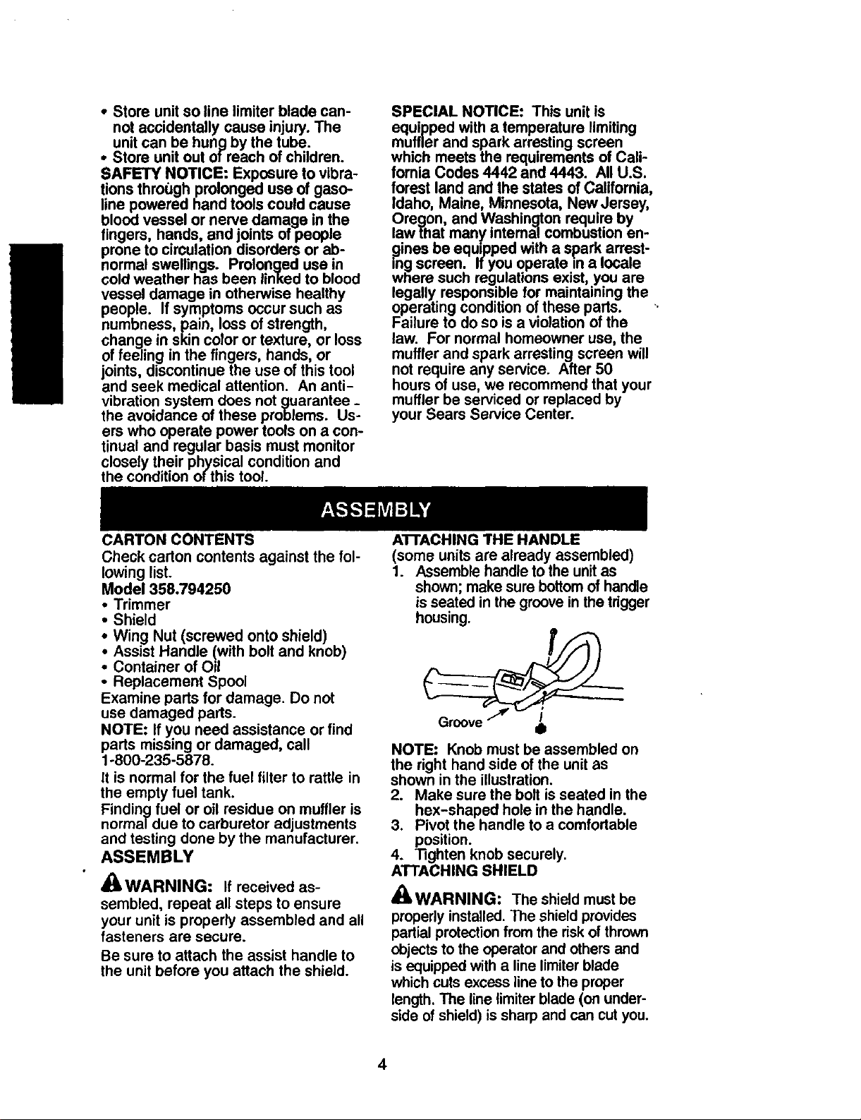
An'ACHING THE HANDLE
(some units are already assembled)
1. Assemble handle to the unit as
shown; make sure bottom of handle
is seated in the groove in the tdgger
housing.
NOTE: Knob must be assembled on
the right hand side of the unit as
shown in the illustration.
2. Make sure the bolt is seated in the
box-shaped hole in the handle.
3. Pivot the handle to a comfortable
position.
4. Tighten knob securely.
ATTACHING SHIELD
_ WARNING: The shield must be
properly installed. The shield provides
partial protection from the risk of thrown
objects to the operator and others and
is equipped with a line limiter blade
which cuts excess line to the proper
length. The line limiter blade (on under-
side of shield) is sharp and can cut you.
4
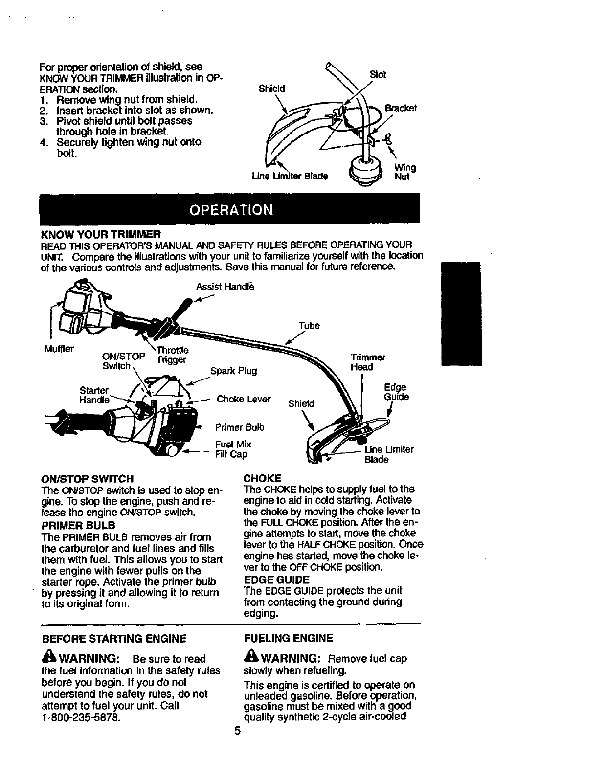
For proper orientation of shield, see
KNOW YOUR TRIMMER illustration in OP-
ERATION section.
1. Remove wing nut from shield.
2. Insert bracket into slot as shown.
3. Pivot shield until bolt passes
through hole in bracket.
4. Securely tighten wing nut onto
bolt.
KNOW YOUR TRIMMER
READ THIS OPERATOR'S MANUAL AND SAFETY RULES BEFORE OPERATING YOUR
UNIT. Compare the illustrations with your unit to familiarize yourself with the location
of the various controls and adjustments. Save this manual for future reference.
Assist Handle
Shield
line Umiter Blade
Tube
Slot
Bracket
\
Wing
Nut
Muffler
ON/STOP Trigger
Switch \ _ Spark Plug
IB, L.7''=----- Fill Cap
ONISTOP SWITCH
The ON/STOP switch is used to stop en-
gine. To stop the engine, push and re-
lease the engine ON/STOP switch.
PRIMER BULB
The PRIMER BULB removes air from
the carburetor and fuel lines and fills
them with fuel. This allows you to start
the engine with fewer pulls on the
starter rope. Activate the primer bulb
' by pressing it and allowing it to return
to its original form.
Tdmmer
Head
OhokeLeverSh,
Fuel Mix
CHOKE
The CHOKE helps to supply fuel to the
engine to aid in cold starling. Activate
the choke by moving the choke lever to
the FULLCHOKE position. After the en-
gine attempts to start, move the choke
lever to the HALF CHOKE position. Once
engine has started, move the choke le-
ver to the OFF CHOKE position.
EDGE GUIDE
The EDGE GUIDE protects the unit
from contacting the ground during
edging.
Edge
Gutde
t
Limiter
Blade
BEFORE STARTING ENGINE
WARNING: Be sure to read
the fuel information inthe safety rules
before you begin. Ifyou do not
understand the safety rules, do not
attempt to fuel your unit.Call
1°800-235-5878.
FUELING ENGINE
_WARNING: Remove fuel cap
slowly when refueling.
This engine is certified to operate on
unleaded gasoline. Before operation,
gasoline must be mixed with a good
quality synthetic 2-cycle air-cooled
5
engine oil. We recommend Craftsman
brand synthebc oil. Mix gasoline and
oil at a ratio of 40:1 (A 40:1 ratio is
obtained by mixing 3.2 ounces of oil
with I gallon of unleaded _.asoline).
DO NOT USE automotive oil or boat oil.
These oils will cause engine damage.
When mixing fuel, follow instructions
printed on container.
Once oil is added to gasoline shake
conta ner momentadly to assure that
the fuel is thoroughly mixed. Always
read and follow the safety rules
relating to fuel before fueling your unit.
IMPORTANT
Experience indicates that alcohol
blended fuels (called gasohol or using
ethanol or methanol) can attract mois-
ture which leads to separation and
formation of acids during storage. -
Acidic gas can damage the fuel sys-
tem of an engine while in storage.
To avoid engine problems, empty the
fuel system before storage for 30 days
or longer. Drain the gas tank start the
engine and let it run until the fuel lines
and carburetor are empty. Use fresh
fuel next season.
Never use engine or carburetor clean-
er products in the fuel tank or perma-
nent damage may occur.
See the STORAGE section for addition-
al information.
HOW TO STOP YOUR UNIT
• To stop the engine, push and re-
lease the engine ON/STOP switch.
The switch will automatically return
to the ON position. Wait 5 seconds
before attempting to restart unit to
allow switch to reset.
• If engine does not stop, move choke
to the FULL CHOKE position.
Engine -._ _"_,,,Jl_
HOW TO START YOUR UNIT
_' WARNING: The trimmer head
will turn while starting the engine.
Avoid any contact with the muffler. A
hot muffler can cause serious burns.
Choke Lever
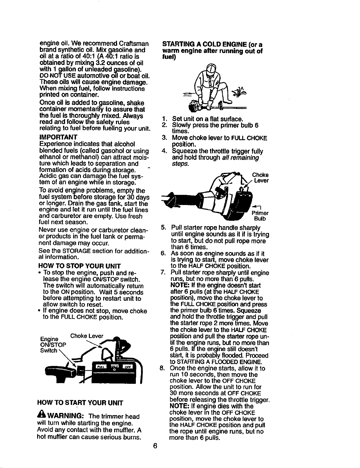
STARTING A COLD ENGINE (or a
warm engine after running out of
fuel)
1. Set unit on a flat surface.
2. Slowly press the pdmer bulb 6
times.
3. Move choke lever to FULL CHOKE
position.
4. Squeeze the throttle tdgger fully
and hold through all remaining
steps.
_j( Choke
Lever
Bulb
5. Pull starter rope handle sharply
until engine sounds as it if is trying
to start, but do not pull rope more
than 6 times.
6. As soon as engine sounds as if it
is trying to start, move choke lever
to the HALF CHOKE position.
7. Pull starter rope sharply until engine
runs, but no more than 6 pulls.
NOTE: If the engine doesn't start
after 6 pulls (at the HALF CHOKE
position), move the choke lever to
the FULL CHOKE position and press
the primer bulb 6 times. Squeeze
and hold the throttle tdg._er and pull
the starter rope 2 more times. Move
the choke lever to the HALF CHOKE
position and pull the starter rope un-
til the engine runs, but no more than
6 pulls. If the engine still doesn't
start, it is probably flooded. Proceed
to STARTING A FLOODED ENGINE.
8. Once the engine starts, allow it to
run 10 seconds, then move the
choke lever to the OFF CHOKE
position. Allow the unit to run for
30 more seconds at OFF CHOKE
before releasing the throttle trigger.
NOTE: If engine dies with the
choke lever in the OFF CHOKE
position, move the choke lever to
the HALF CHOKE position and pull
the rope until engine runs, but no
more than 6 pulls.
6
STARTING A WARM ENGINE
1. Move the choke lever to the HALF
CHOKEposition.
2. Squeeze and hold the throttle trig-
ger. Keep throttle trigger fully
squeezed untilthe engine runs
smoothly.
3. Pull starter rope sharply untilengine
runs,but nomore than5 pulls.
4. Allow engine to run 15 seconds,
then move the choke lever to the
OFF CHOKE position.
NOTE: If engine has not staded, pull
starter rope 5 more pulls. If engine still
does not run, it is probably flooded.
STARTING A FLOODED ENGINE
Flooded engines can be started by
placing the choke lever in the OFF
CHOKE position; then, pull the rope to
clear the engine of excess fuel. This
could require pulling the starter handle
many times depending on how badly
the unit is flooded.
If the unit still doesn't start, refer to
TROUBLESHOOTING TABLE or call
1-800-235-5878•
OPERATING INSTRUCTIONS
It is recommended that the engine
not be operated for longer than 1
minute at full throttle.
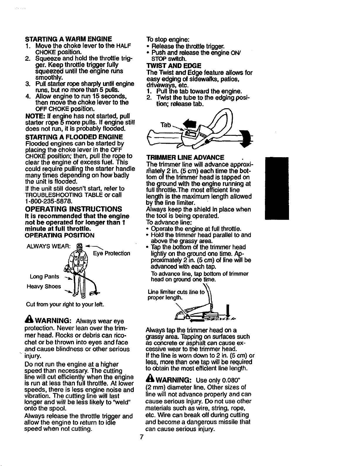
OPERATING POSITION
ALWAYS WEAR:
EyeProtection
Long Pants
Heavy Shoes
Cut from your right to your left.
Tostop engine:
• Release the throttletrigger.
• Push and releasethe engineON/
STOPswitch.
TWIST AND EDGE
The Twist and Edge feature allows for
easy edging of sidewalks, patios,
driveways, etc.
1. Pull the tab toward the engine.
2. Twist the tube to the edging posi-
tion; release tab.
TRIMMER LINE ADVANCE
The trimmer linewilladvance approxi-
r_ataly 2 in. (5 cm) each time the bot-
tom of the trimmer head istapped on
the ground with the engine running at
full throttle.The mostefficient line
length is the maximum length allowed
by the line limiter.
Always keep the shield inplace when
the tool isbeing operated.
To advance line:
• Operate the engineat fullthrottle.
• Holdthe trimmerhead parallelto and
above the grassyarea.
• Tapthe bottom ofthe trimmerhead
lightlyon the groundone time. Ap-
proximately2 in. (5 cm) of line willbe
advancedwith eachtap.
Toadvanceline,tap bottomoftrimmer
headon groundone time.
Line limiter cuts
properlength.
'AWARNING: Always wear eye
protection. Never lean over the trim-
mer head. Rocks or debris can rico-
chet or be thrown into eyes and face
and cause blindness or other serious
injury.
Do not run the engine at a higher
speed than necessary. The cutting
line will cut efficiently when the engine
is run at less than full throttle• At lower
speeds, there is less engine noise and
vibration. The cutting line will last
longer and will be less likely to "weld"
onto the spool.
Always release the throttle trigger and
allow the engine to return to idle
speed when not cutting.
Always tap the trimmer head on a
grassy area. Tappingon surfaces such
as concrete or asphalt can cause ex-
cessive wear to the trimmer head.
If the line is worn down to 2 in. (5 crn) or
less, more than one tap will be required
to obtain the most efficient line length.
_kWARNING: Use only 0.080"
(2 ram) diameter line. Other sizes of
line will not advance properly and can
cause serious injury. Do not use other
materials such as wire, string, rope,
etc. Wire can break off during cutting
and become a dangerous missile that
can cause serious injury.
7
CU'I-rlNG METHODS
Use minimum speed and do not
crowd the line when cutting around
hard objects (rock, gravel, fence
posts, etc.), which can damage the
trimmer head, become entangled in
the line, or be thrown causing a sed-
ous hazard.
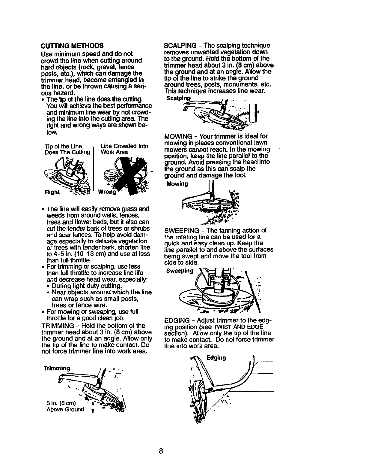
SCALPING - The scalpingtechnique
removes unwanted vegetation down
to the ground. Holdthe bottomof the
trimmer head about 3 ,n. (8 cm) above
the ground and at an angle. Allow the
tip ol the line to strike the ground
around trees, posts, monuments, etc.
This technique increases line wear.
• The tip of the linedoesthe cutting.
You willach=evethe best performance
Scalpl_o "_ .....
and minimumline wear by notcrowd-
ingthe line into the cuttingarea. The
rightand wrong ways are shownbe-
low.
Tip ofthe Line Line Crowded Into
MOWING - Your trimmer is ideal for
mowing in places conventional lawn
DoesThe Cutting WorkArea mowers cannot reach. In the mowing
ground. Avoid pressingthe head into
the ground as this can scalp the
ground and damage the tool.
_l _g_ position, keep the line parallel to the
"_'_ Mowing Ii
W , =lN
• The line will easilyremove grassand __'
weeds from aroundwalls, fences,
trees and flower beds,but it also can ,.._._._._'_"
cut the tender bark of trees or shrubs
and scar fences. To help avoid dam-
age especially to delicate vegetation
or trees with tender bark, shorten line
to 4-5 in. (10-13 cm) and use at less
than lull throttle.
• For trimming or scalping, use less
than full throttle to increase line life
and decrease head wear, especially:
: During light duty cutting.
Near objects around which the line
can wrap such as small posts,
trees or fence wire.
• For mowing or sweeping, use full
throttle for a good clean job.
TRIMMING - Hold the bottom of the
trimmer head about 3 in. (8 cm) above
the ground and at an angle. Allow only
the tip of the line to make contact. Do
not force trimmer line into work area.
SWEEPING - The fanning action of
the rotating line can be used for a
quick and easy clean up. Keep the
line parallel to and above the surfaces
being swept and move the tool from
side to side.
Sweeping ' " •
EDGING - Adjust trimmer to the edg-
ing position (see TWIST AND EDGE
section). Allow only the tip of the line
to make contact. Do not force trimmer
line into work area.
Trimming ,,..
J,
8
MAINTENANCE SCHEDULE
_, WARNING: Disconnect the spark plug before performing maintenance
except for carburetor adjustments,
CARE & MAINTENANCE TASK WHEN TO PERFORM
Check for loose fasteners and parts
Check for damaged or worn pads
Inspect and clean unit and labels
Clean air filter
Inspect muffler and spark arresting screen
Replace spark plug
Before each usa
Before each use
After each use
Every 5 hours of operation
Every 50 hoursof operation
Yearly
GENERAL RECOMMENDATIONS
The warranty on this unit does not
cover items that have been subjected
to operator abuse or negligence. To
receive full value from the warranty,
the operator must maintain unit as
instructed in this manual. Various ad-
justments will need to be made peri-
odically to properly maintain your unit.
CHECK FOR LOOSE
FASTENERS AND PARTS
• Spark Plug Boot
• Air Filter
• Housing Screws
Assist Handle Screws
• Debris Shield
CHECK FOR DAMAGED OR
WORN PARTS
Contact Sears Service Center for re-
placement of damaged or wom pads.
• ON/STOP Switch - Ensure OWSTOP
switch functions properly by pushing
and releasing the switch. Make sure
engine stops. Wait 5 seconds before
attempting to restart unit to allow
switch to reset. Restart engine and
continue.
• Fuel Tank - Discontinue use of unit if
fuel tank shows signs of damage or
leaks.
• Debris Shield - Discontinue use of
unit if debris shield is damaged.
INSPECT AND CLEAN UNff AND
LABELS
• Aftereach use, inspectcompleteunit
for looseor damagedpads. Clean
the unit and labels usinga dampcloth
with a milddetergent.
• Wipe offunitwith a clean drycloth.
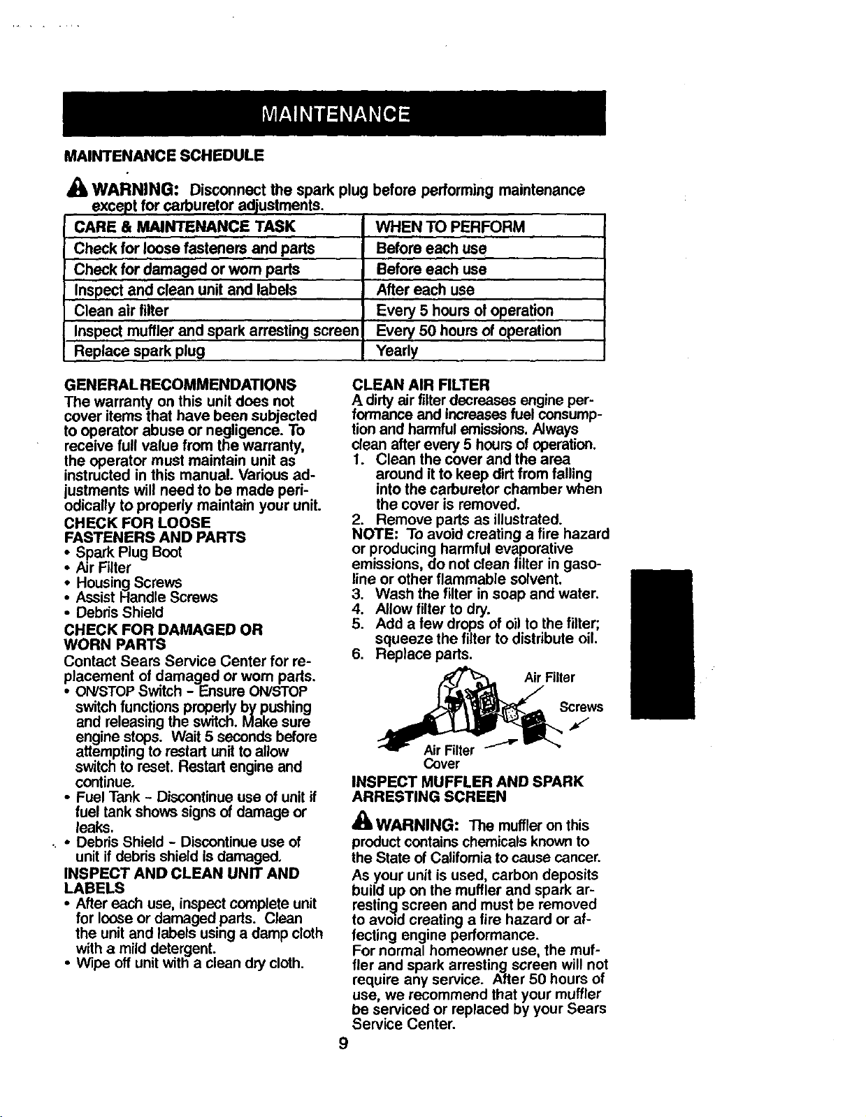
CLEAN AIR FILTER
A dirty air filter decreases engine per-
formance and increases fuel consump-
tion and harmful emissions. Always
clean after every 5 hours of operation.
1. Clean the cover and the area
around it to keep dirt from falling
into the carburetor chamber when
the cover is removed.
2. Remove parts as illustrated.
NOTE: To avoid creating a fire hazard
or producing harmful evaporative
emissions, do not clean filter in gaso-
line or other flammable solvent.
3. Wash the filter in soap and water.
4. Allow filter to dry.
5. Add a few drops of oil to the filter;
squeeze the filter to distribute oil.
6. Replace pads.
_S Filter
crews
J
Cover
INSPECT MUFFLER AND SPARK
ARRESTING SCREEN
_ WARNING: The muffler on this
product contains chemicals known to
the State of California to cause cancer.
As your unit is used, carbon deposits
build up on the muffler and spark ar-
restin_l screen and must be removed
to avoid creating a fire hazard or af-
fecting engine performance.
For normal homeowner use, the muf-
fler and spark arresting screen will not
require any service. After 50 hours of
use, we recommend that your muffler
be serviced or replaced by your Sears
Service Center.
9
REPLACE SPARK PLUG
Replace the spark plug each year to
ensure the engine starts easier and
runs better. Set spark plug gap at
0.025 in. Ignition timing is fixed and
nonadjustable.
1. Twist, then pull off spark plug boot.
2. Remove spark plug from cylinder
and discard.
3. Replace with Champion RCJ-7Y
spark plugand tighten with a 3/4
in. socket wrench (10-12 ft.-Ibs).
4. Reinstall the spark plug boot.
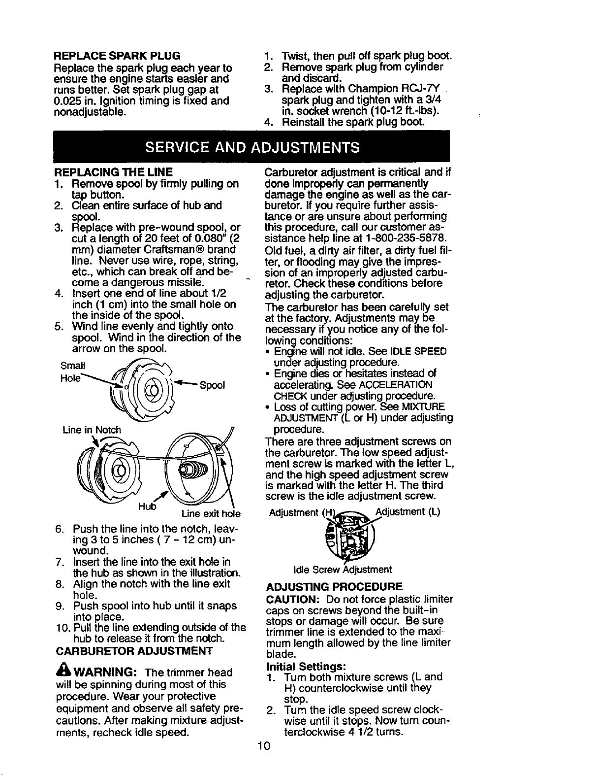
REPLACING THE LINE
1. Remove spool by firmly pulling on
tap button.
2. Clean entire surface of hub and
spool.
3. Replace with pre-wound spool, or
cut a length of 20 feet of 0.080' (2
ram) diameter Craftsman® brand
line. Never use wire, rope, string,
etc., which can break off and be-
come a dangerous missile.
4. Insert one end of line about 1/2
inch (1 cm) into the small hole on
the inside of the spool.
5. Wind line evenly and tightly onto
spool. Wind in the direction of the
arrow on the s_ool.
Small .,_
_ Spool
Line in Notch
Hub
Une exit hole
6. Push the line into the notch, leav-
ing 3 to 5 inches ( 7 - 12 cm) un-
wound.
7. Insert the line into the exit hole in
the hub as shown in the illustration.
8. Align the notch with the line exit
hole.
9. Push spool into hub until it snaps
into place.
10. Pull the line extending outside of the
hub to release it from the notch.
CARBURETOR ADJUSTMENT
_WARNING: Thetrimmer head
will be spinning during most of this
procedure, Wear your protective
equipment and observe all safety pre-
cautions. After making mixture adjust-
ments, recheck idle speed.
Carburetor adjustment iscritical and if
done improperly can permanently
damage the engine as well as the car-
buretor. If you require further assis-
tance or are unsure about performing
this procedure, call our customer as-
sistance help line at 1-800-235-5878.
Old fuel, a dirty air filter, a dirty fuel fil-
ter, orflooding may give the impres-
sion of an improperly adjusted carbu-
retor. Check these conditions before
adjusting the carburetor.
The carburetor has been carefully set
at the factory. Adjustments may be
necessary if you notice any of the fol-
lowing conditions:
• Engine will not idle. See IDLESPEED
under adjusting procedure.
• Engine dies or hesitatesinstead of
accelerating. See ACCELERATION
CHECKunder adjustingprocedure.
• Loss of cuttingpower.See MIXTURE
ADJUSTMENT(L or H) under adjusting
procedure.
There are three adjustment screws on
the carburetor. The low speed adjust-
ment screw is marked with the letter L,
and the high speed adjustment screw
is marked with the letter H. The third
screw is the idle adjustment screw.
Adjustment (_ojustment (L)
Idle Screw Adjustment
ADJUSTING PROCEDURE
CAUTION: Do not force plastic limiter
caps on screws beyond the built-in
stops or damage will occur. Be sure
trimmer line is extended to the maxi-
mum length allowed by the line limiter
blade.
Initial Settings:
1. Turn both mixture screws (L and
H) counterclockwise until they
stop.
2. Turn the idle speed screw clock-
wise until it stops. Now turn coun-
terclockwise 4 1/2 turns.
10
3. Startengine,cutgrassfor 3 min-
utes, then proceed to adjust
screws according to the instruc-
tions below. If engine perfor-
mance at initial settings is accept-
able, no further adjustments are
necessary. If engine does not
start, refer to TROUBLESHOOTING
TABLE. If still unable to remedy sit-
uation, call 1-800-235-5878.
Idle Speed
Allow engine to idle. Adjust speed until
engine runs without stalling.
Turn idle speed screw clockwiseto
increase engine speed if engine
stalls ordies.
• Turn idle speed screw counterclock-
wise to decrease engine speed.
No further adjustments are necessary
ifperformance is satisfactory.
Low Speed Mixture Adjustment - L
1. Allow the engine to idle.
2. Turn low speed mixture screw (L)
slowly clockwise until the speed
begins to drop.
3. Turn the low speed mixture screw
(L) counterctockwise until the
speed increases and then starts to
drop again.
4. Set the low speed mixture screw
(L) at the midpoint between the
two positions.
Readjust the idle speed (See IDLE
SPEED).
High Speed Mixture Adjustment - H
CAUTION: Do not operate engine at
full throttle for prolonged pedods while
making adjustments as damage to the
engine can occur. Adjustthe mixture
screw 1/16 of a turn at a time. A 1/16
turn is about the width of the slot in the
top of the screw.
1. Allowthe engine to idle.
2. Squeeze the throttle trigger fully.
Turn the high speed mixture screw
(H) counterclockwise until it stops.
3. Turnthe highspeed mixture screw
(H) 1/16 of a turn clockwiseat a
time untilthe engine runssmoothly.
After completing adjustments, check
for acceleration. Reset if necessary.
Acceleration Check
If engine dies or hesitates instead of
accelerating, turn the low speed mix-
ture screw (L) counterclockwise until
you have smooth acceleration.
WARNING: Perform the follow-
ing steps after each use:
• Allow engine to cool, and secure the
unitbefore storing or transporting.
• Store unitand fuel ina well ventilated
area where fuel vapors cannot reach
sparks or open flames from water
heaters, electric motors or switches,
furnaces, etc.
• Store unitwith all guards in place.
Positionunit so that any sharp object
cannot accidentally cause injury.
• Store unitand fuel well out of the
reach of children.
SEASONAL STORAGE
Prepare unit for storage at end ofsea-
son or if it will not be used for 30 days
OF more.
ifyour unit is to be stored for a period
of time:
• Clean the entire unitbefore lengthy
storage.
• Store ina clean dry area.
Lightlyoilextemal metal surfaces.
FUEL SYSTEM
Under FUELING ENGINE in the OPERA-
TION section of this manual, see mes-
sage labeled IMPORTANT regarding
the use of gasohol in your engine.
Fuel stabilizer is an acceptable alter-
native in minimizing the formation of
fuel gum deposits during storage. Add
stabilizer to the gasoline in the fuel
tank or fuel storage container. Follow
the mix instructions found on stabilizer
container. Run engine at least 5 min-
utes after adding stabilizer.
Craftsman 40:1, 2-cycle engine oil (air
cooled) is already blended with fuel
stabilizer. If you do not use this Sears
oil, you can add a fuel stabilizer to
your fuel tank.
11
 Loading...