

Craftsman 358742470 Owner’s Manual

Operator's Manual
®
CRRFTSMRN
24cc 2-Cycle Engine
17 Inch Cutting Path/.080 In. Line
GASOLINE BRUSHWACKER ®
Model No.
358.742470
_ ANGER:
_) For answers to your questions about this product:
Read and follow all Safety Rules and Operating
Instructions before first use of this product.
Call 7 am-7 pm, Mon-Sat; Sun, 10 am-7 pm
1-800-235-5878 (Hours listed are Central Time)
Sears, Roebuck and Co., Hoffman Estates, IL 60179 USA
530088637 11/15/99

Warranty Statement 2 Storage 15
Safety Rules 2 Troubleshooting Chart 16
Assembly 5 Emissions Statement 16
Operation 8 Parts List 18
Maintenance 12 Spanish 21
Service & Adjustments 13 Parts and Ordering Back
FULL ONE YEAR WARRANTY ON CRAFTSMAN GAS POWERED
BRUSHWACKER ® BLADED TRIMMER.
For one year from the date of purchase, when this Craftsman Gas Powered
Brushwacker is maintained, lubricated and tuned up according to the operating
and maintenance instructions in the Operator's Manual, Sears will repair, free of
charge, any defect in materials or workmanship.
This warranty excludes the blade, nylon line, spark plug, and air filter, which are
expendable parts and become worn during normal use.
If this Brushwacker is used for commercial purposes, this warranty applies for only
90 days from the date of purchase. If this Brushwacker is used for rental purposes,
this warranty applies for only 30 days from the date of purchase. This warranty ap-
plies only while this product is in use in the United States.
WARRANTY SERVICE IS AVAILABLE BY RETURNING THE BRUSHWACKER TO THE
NEAREST SEARS SERVICE CENTER IN THE UNITED STATES.
This warranty gives you specific legal rights, and you may also have other rights
which vary from state to state.
Sears, Roebuck and Co., 0/817 WA Hoffman Estates, IL 60179
DANGER: This power tool can be
dangerous! This unit can cause serious
injury including amputation or blindness
to the operator and others. The warn-
ings and safety instructions in this man-
ual must be followed to provide reason-
able safety and efficiency in using the
unit. The operator is responsible for fol-
lowing the warnings and instructions in
this manual and on the unit. Read the
entire Operator's Manual before assem*
bling and using the unit! Restrictthe use
of this unit to persons who read, under-
stand, and follow the warnings and in-
structions in this manual and on the unit.
Never allow children to use this unit.
A__ __
_WARNING: Follow all warnings
and instructions. Failure to do so can
result in serious injury.
_, DANGER: Blade can thrust vio-
lently away from material it does not
cut. Blade thrust can cause amputa-
tion of arms or legs. Keep people and
animals 50 feet (15 meters) away.
2
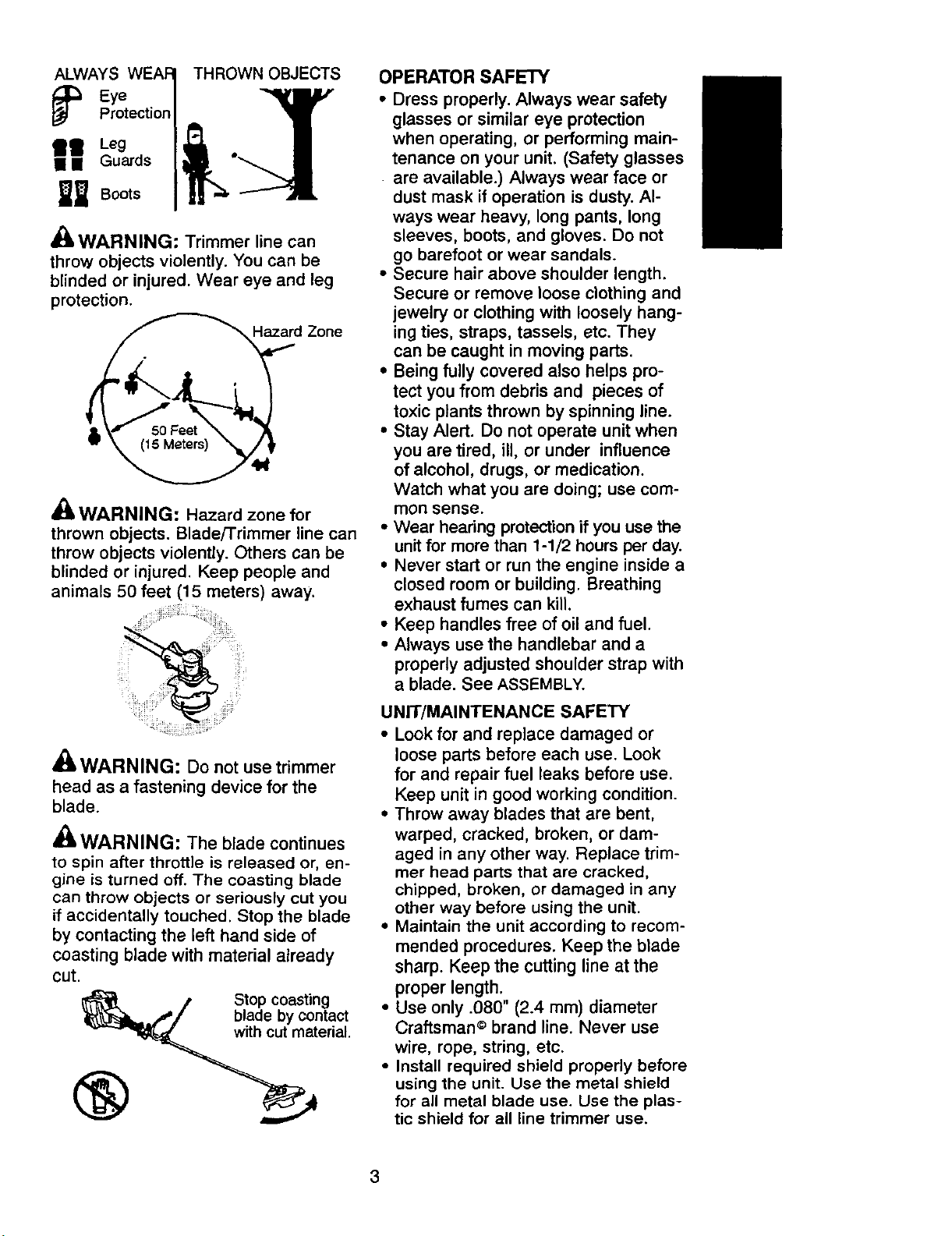
ALWAYS THROWN OBJECTS
" r° tecticn/ .li
Eye 1
Boots | I! _ --'----
_k WARNING: Trimmer line can
throw objects violently. You can be
blinded or injured. Wear eye and leg
protection.
d Zone
A
dBt,WARNING: Hazard zone for
thrown objects. Blade/Trimmer line can
throw objects violently. Others can be
blinded or injured. Keep people and
animals 50 feet (15 meters) away.
OPERATOR SAFETY
• Dress properly. Always wear safety
glasses or similar eye protection
when operating, or performing main-
tenance on your unit. (Safety glasses
are available.) Always wear face or
dust mask if operation is dusty. Al-
ways wear heavy, long pants, long
sleeves, boots, and gloves. Do not
go barefoot or wear sandals.
• Secure hair above shoulder length.
Secure or remove loose clothing and
jewelry or clothing with loosely hang-
ing ties, straps, tassels, etc. They
can be caught in moving parts.
• Being fully covered also helps pro-
tect you from debris and pieces of
toxic plants thrown by spinning line.
• Stay Alert. Do not operate unit when
you are tired, ill, or under influence
of alcohol, drugs, or medication.
Watch what you are doing; use com-
mon sense.
• Wear hearing protection if you use the
unit for more than 1-1/2 hours per day.
• Never start or run the engine inside a
closed room or building. Breathing
exhaust fumes can kill.
• Keep handles free of oil and fuel.
• Always use the handlebar and a
properly adjusted shoulder strap with
a blade. See ASSEMBLY.
A
41WARNING: Do not use trimmer
head as a fastening device for the
blade.
_IL WARNING: The blade continues
to spin after throttle is released or, en-
gine is turned off. The coasting blade
can throw objects or seriously cut you
if accidentally touched. Stop the blade
by contacting the left hand side of
coasting blade with material already
cut.
Stop coasting
blade by contact
with cut material.
®
UNIT/MAINTENANCE SAFETY
• Look for and replace damaged or
loose parts before each use. Look
for and repair fuel leaks before use.
Keep unit in good working condition.
• Throw away blades that are bent,
warped, cracked, broken, or dam-
aged in any other way. Replace trim-
mer head parts that are cracked,
chipped, broken, or damaged in any
other way before using the unit.
• Maintain the unit according to recom-
mended procedures. Keep the blade
sharp. Keep the cutting line at the
proper length.
• Use only .080" (2.4 mm) diameter
Craftsman © brand line. Never use
wire, rope, string, etc.
• Install required shield properly before
using the unit. Use the metal shield
for all metal blade use. Use the plas-
tic shield for all line trimmer use.
3

• Use only specified blade or trimmer
head; make sure it is properly in-
stalled and securely fastened.
• Never start engine with clutch shroud
removed. The clutch can fly off and
cause serious injury.
• Be sure blade or trimmer head stops
turning when engine idles.
• Disconnect the spark plug before
performing maintenance (except car-
buretor adjustments).
• Make carburetor adjustments with
the lower end supported to prevent
the blade or trimmer line from con-
tacting any object. Hold the unit by
hand; do not use the shoulder strap
for support.
• Keep others away when making car-
buretor adjustments.
• Use only recommended Craftsman
accessories and replacement parts.
• Have all maintenance and service
not explained inthis manual per-
formed by a Sears Service Center.
FUEL SAFETY
• Mix and pour fuel outdoors.
• Keep away from sparks orflames.
• Use a container approved for fuel.
• Do not smoke or allow smoking near
fuel or the unit or while using the unit.
• Wipe up all fuel spills before starting
engine.
• Move at least 10 feet (3 meters) away
from fueling site before starting engine.
• Stop engine and allow it to cool be-
fore removing fuel cap.
• Empty the fuel tank before storing
the unit. Use up fuel left in the carbu-
retor by starting the engine and let-
ting it run until it stops.
• Store unit and fuel in an area where
fuel vapors cannot reach sparks or
open flames from water heaters, elec-
tric motorsor switches, furnaces, etc.
CU'I-rlNG SAFETY
• Inspect the area to be cut before
each use. Remove objects (rocks,
broken glass, nails, wire, string, etc.)
which can be thrown or become en-
tangled in the blade or trimmer head.
• Keep others including children, ani-
mals, bystanders, and helpers at
least 50 feet (15 meters) away. Stop
the engine immediately if you are ap-
proached.
• Always keep engine on the right-
hand side of your body.
• Hold the unit firmly with both hands.
• Keep firm footing and balance. Do
not overreach.
• Keep blade or trimmer head below
waist level,
• Do not raise engine above your waist.
• Keep all parts of your body away
from blade, trimmer head, and muf-
fler when engine is running.
• Cut from your right to your left.
• Use only for jobs explained in this
manual.
TRANSPORTING AND STORAGE
• Stop the unit before carrying.
• Keep muffler away from your body.
• Allow engine to cool and secure unit
before storing or transporting it in a
vehicle.
• Empty the fuel tank before storing or
transporting the unit. Use up fuel left
in the carburetor by starting the en-
gine and letting it run until it stops.
• Store unit and fuel in an area where
fuel vapors cannot reach sparks or
open flames from water heaters,
electric motors or switches, furnaces,
etc.
• Store unit so the blade or line limiter
cannot accidentally cause injury. The
unit can be hung by the tube.
• Store unit out of reach of children.
SPECIAL NOTICE: This unitis not
equipped with a temperature limiting
muffler and spark arresting screen
which meets the requirements of Cali-
fornia Codes 4442 and 4443. All U.S.
forest land and the states of California,
Idaho, Maine, Minnesota, New Jersey,
Oregon, and Washington require by
law that many internal combustion en-
gines be equipped with a spark arres-
tor screen. Ifyou operate in a locale
where such regulations exist, you are
legally responsible for installing and
maintaining the operating condition of
these parts. Failure to do so is a viola-
tion of the law. Refer to the MAINTE-
NANCEsection in this manual.
SPECIAL NOTICE: Exposure to vibra-
tions through prolonged use of gaso-
line powered hand tools could cause
blood vessel or nerve damage in the
fingers, hands, and joints of people
prone to circulation disorders or abnor-
mal swellings. Prolonged use in cold
weather has been linked to blood ves-
4
sel damage in otherwise healthy
people. If symptoms occur such as
numbness, pain, loss of strength,
change in skin color or texture, or loss
of feeling in the fingers, hands, or
joints, discontinue the use of this tool
and seek medical attention. An anti-
vibration system does not guarantee
the avoidance of these problems. Us-
ers who operate power tools on a con-
tinual and regular basis must monitor
closely their physical condition and the
condition of this tool.
CARTON CONTENTS
Check carton contents against the fol-
lowing list.
Model: 358.7'42470
• Brushcutter
• Handlebar screws (2)
• Blade shield screws (4)
• Cupped washer
• Large nut for installing blade
• Long hex wrench
• Short hex wrench
• Bracket cover
• Metal shield
• Plastic shield
• Shoulder strap with warning
• Weed blade
• Trimmer head
• Handlebar
• Container of oil
Examine parts for damage. Do not use
damaged parts.
NOTE: If you need assistance or find
that parts are missing or damaged, call
1-800-235-5878.
It is normal for the fuel filter to rattle in the
empty fuel tank.
Finding fuel or oil residue on muffler is
normal due to carburetor adjustments
and testing done by the manufacturer.
ASSEMBLY
WARNING: If received as-
sembled, repeat all steps to ensure your
unit is properly assembled and all fas-
teners are secure.
TOOLS REQUIRED
• 2 hex wrenches (provided)
• adjustable wrench or large pliers
• phillips screwdriver
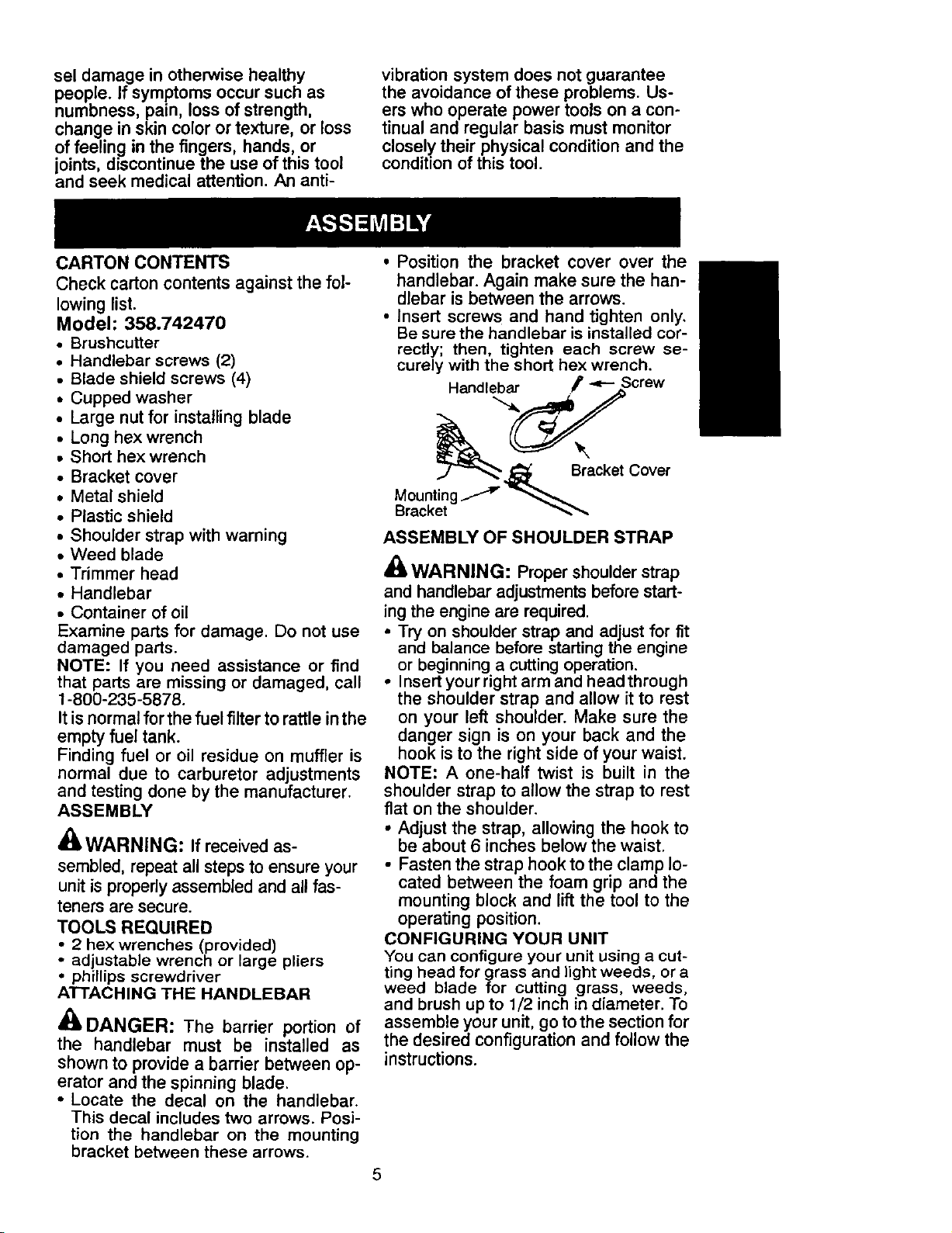
ATTACHING THE HANDLEBAR
DANGER: The barrier portion of
the handlebar must be installed as
shown to provide a barrier between op-
erator and the spinning blade.
• Locate the decal on the handlebar.
This decal includes two arrows. Posi-
tion the handlebar on the mounting
bracket between these arrows.
• Position the bracket cover over the
handlebar. Again make sure the han-
dlebar is between the arrows.
• Insert screws and hand tighten only.
Be sure the handlebar is installed cor-
rectly; then, tighten each screw se-
curely with the short hex wrench.
Handlebar F "P- Screw
.j_ Bracket Cover
ASSEMBLY OF SHOULDER STRAP
_-WARNING: Proper shoulderstrap
and handlebar adjustments before start-
ing the engine are required.
• Try on shoulder strap and adjust for fit
and balance before starting the engine
or beginning a cutting operation.
• Insert your right arm and head through
the shoulder strap and allow it to rest
on your left shoulder. Make sure the
danger sign is on your back and the
hook is to the right side of your waist.
NOTE: A one-half twist is built in the
shoulder strap to allow the strap to rest
flat on the shoulder.
• Adjust the strap, allowing the hook to
be about 6 inches below the waist.
• Fasten the strap hook to the clamp lo-
cated between the foam grip and the
mounting block and lift the tool to the
operating position.
CONFIGURING YOUR UNIT
You can configure your unit using a cut-
ting head for grass and light weeds, or a
weed blade for cutting grass, weeds,
and brush up to 1/2 inch in diameter. To
assemble your unit, go tothe section for
the desired configuration and follow the
instructions.
5
ASSEMBLY INFORMATION - TRIM-
MER HEAD
HEAD
TRIMMER
NOTE: Make sure all parts are properly
installed as illustrated in the illustration
before installing the trimmer head.
• Align hole inthe dustcup withthe hole
in the side of the gearbox by rotating
the dust cup.
• Insert a small screwdriver into aligned
holes. This will keep the shaft from
turning while tightening trimmer head.
Screwdriver
NOTE: If your unit has been assembled
for weed blade use, refer to the section
ASSEMBLY INFORMATION FOR USING
YOUR UNIT WITH A WEED BLADE and re-
verse the steps to remove the metal
shield and blade before you mount the
plastic shield and trimmer head.
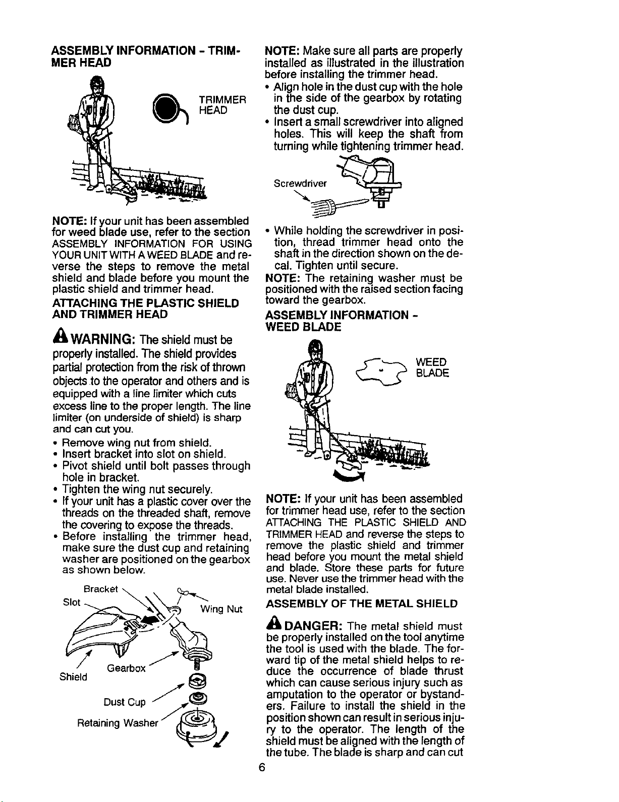
ATTACHING THE PLASTIC SHIELD
AND TRIMMER HEAD
A
EL WARNING: The shield must be
properly installed. The shield provides
partial protection from the risk of thrown
objects.tothe operator and others and is
equipped with a line limiter which cuts
excess line to the proper length. The line
limiter (on underside of shield) is sharp
and can cut you.
• Remove wing nut from shield.
• Insert bracket into slot on shield.
• Pivot shield until bolt passes through
hole in bracket.
• Tighten the wing nut securely.
• If your unithas a plasticcover over the
threads on the threaded shaft, remove
the covering to expose the threads.
• Before installing the trimmer head,
make sure the dust cup and retaining
washer are positioned on the gearbox
as shown below.
Bracket _.
Slot "_..."_/_ing Nut
Shield
DustCup //J_
RetainingWasherJ(?_j
• While holding the screwdriver in posi-
tion, thread trimmer head onto the
shaft in the direction shown on the de-
cal. Tighten until secure.
NOTE: The retaining washer must be
positioned with the raised section facing
toward the gearbox.
ASSEMBLY INFORMATION -
WEED BLADE
BLADE
WEED
NOTE: If your unit has been assembled
for trimmer head use, refer to the section
ATTACHING THE PLASTIC SHIELD AND
TRIMMER HEAD and reverse the steps to
remove the plastic shield and trimmer
head before you mount the metal shield
and blade. Store these parts for future
use. Never use the trimmer head with the
metal blade installed.
ASSEMBLY OF THE METAL SHIELD
DANGER: The metal shield must
be properly installed on the tool anytime
the tool is used with the blade. The for-
ward tip of the metal shield helps to re-
duce the occurrence of blade thrust
which can cause serious injury such as
amputation to the operator or bystand-
ers. Failure to install the shield in the
position shown can result inserious inju-
ry to the operator. The length of the
shield must be aligned with the length of
the tube. The blade issharp and can cut
6
you. Be sure to wear gloves while work-
ing with blades.
• If your unit has a plastic cover over the
threads on the shaft, remove the cov-
ering to expose the threads.
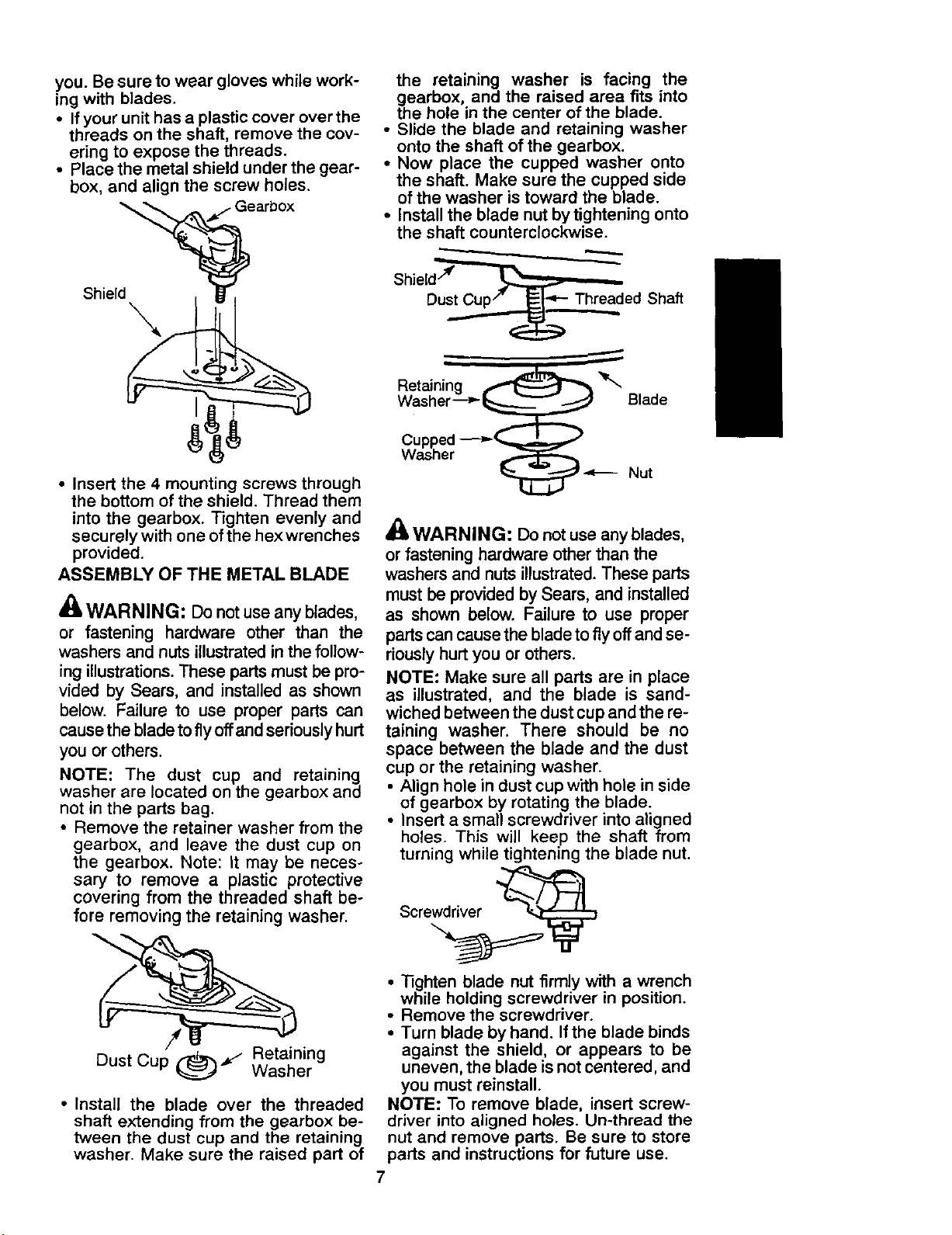
• Place the metal shield under the gear-
box, and align the screw holes.
the retaining washer is facing the
gearbox, and the raised area fits into
the hole in the center of the blade.
• Slide the blade and retaining washer
onto the shaft of the gearbox.
• Now place the cupped washer onto
the shaft. Make sure the cupped side
of the washer is toward the blade.
• Install the blade nut by tightening onto
the shaft counterclockwise.
Shield
• Insert the 4 mounting screws through
the bottom of the shield. Thread them
into the gearbox. Tighten evenly and
securely with one of the hex wrenches
provided.
ASSEMBLY OF THE METAL BLADE
_(_ WARNING: Do not use any blades,
or fastening hardware other than the
washers and nuts illustrated in the follow-
ing illustrations. These parts must be pro-
vided by Sears, and installed as shown
below. Failure to use proper parts can
cause the blade to fly offand seriously hurt
you or others.
NOTE: The dust cup and retaining
washer are located on the gearbox and
not in the parts bag.
• Remove the retainer washer from the
gearbox, and leave the dust cup on
the gearbox. Note: It may be neces-
sary to remove a plastic protective
covering from the threaded shaft be-
fore removing the retaining washer.
Shield/_' _
Dust Cup/" _=_"_- Threaded Shaft
Retaining _
Washer--__ Blade
Cupped ---__
Washer
_1._ _ Nut
A(_WARNING: Donot use any blades,
or fastening hardware other than the
washers and nuts illustrated. These parts
must be provided by Sears, and installed
as shown below. Failure to use proper
parts can cause the blade to fly off and se-
riously hurt you or others.
NOTE: Make sure all parts are in place
as illustrated, and the blade is sand-
wiched between the dust cup and the re-
taining washer. There should be no
space between the blade and the dust
cup or the retaining washer.
• Align hole in dust cup with hole in side
of gearbox by rotating the blade.
• Insert a small screwdriver into aligned
holes. This will keep the shaft from
turning while tightening the blade nut.
Scre@_
Dust Cup _l
• Install the blade over the threaded
shaft extending from the gearbox be-
tween the dust cup and the retaining
washer. Make sure the raised part of
Retaining
Washer
• _ghten blade nut firmly with a wrench
while holding screwdriver in position.
• Remove the screwdriver.
• Turn blade by hand. If the blade binds
against the shield, or appears to be
uneven, the blade is not centered, and
you must reinstall.
NOTE: To remove blade, insert screw-
driver into aligned holes. Un-thread the
nut and remove parts. Be sure to store
parts and instructions for future use.
7
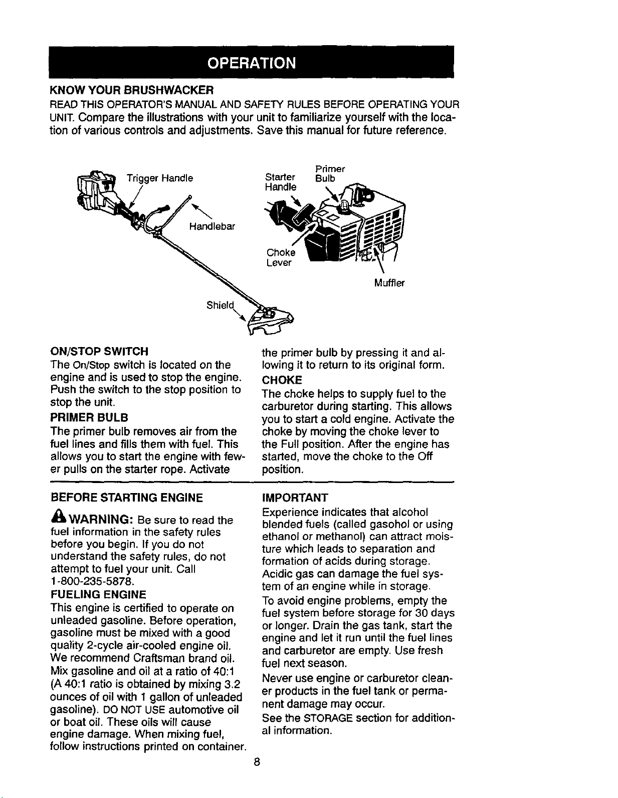
KNOWYOUR BRUSHWACKER
READTHIS OPERATOR'S MANUAL AND SAFETY RULES BEFORE OPERATING YOUR
UNIT. Compare the illustrations with your unit to familiarize yourself with the loca-
tion of various controls and adjustments. Save this manual for future reference.
Primer
Trigger Handle Starter Bulb
Handlebar
ShieldX
Handle
Muffler
ON/STOP SWITCH
The On/Stop switch is located on the
engine and is used to stop the engine.
Push the switch to the stop position to
stop the unit.
PRIMER BULB
The primer bulb removes air from the
fuel lines and fills them with fuel. This
allows you to start the engine with few-
er pulls on the starter rope. Activate
BEFORE STARTING ENGINE
_WARNING: Be sure to read the
fuel information in the safety rules
before you begin. If you do not
understand the safety rules, do not
attempt to fuel your unit. Call
1-800-235-5878.
FUELING ENGINE
This engine is certified to operate on
unleaded gasoline. Before operation,
gasoline must be mixed with a good
quality 2-cycle air-cooled engine oil.
We recommend Craftsman brand oil.
Mix gasoline and oil at a ratio of 40:1
(A 40:1 ratio is obtained by mixing 3.2
ounces of oil with 1 gallon of unleaded
gasoline). DO NOT USE automotive oil
or boat oil. These oils will cause
engine damage. When mixing fuel,
follow instructions printed on container.
the primer bulb by pressing it and al-
lowing it to return to its original form.
CHOKE
The choke helps to supply fuel to the
carburetor during starting. This allows
you to start a cold engine. Activate the
choke by moving the choke lever to
the Full position. After the engine has
started, move the choke to the Off
position.
IMPORTANT
Experience indicates that alcohol
blended fuels (called gasohol or using
ethanol or methanol) can attract mois-
ture which leads to separation and
formation of acids during storage.
Acidic gas can damage the fuel sys-
tem of an engine while in storage.
To avoid engine problems, empty the
fuel system before storage for 30 days
or longer. Drain the gas tank, start the
engine and let it run until the fuel lines
and carburetor are empty. Use fresh
fuel next season.
Never use engine or carburetor clean-
er products in the fuel tank or perma-
nent damage may occur.
See the STORAGE section for addition-
al information.
STOPPING YOUR ENGINE
• Move the ON/STOP switch to the
STOP position.
• If engine does not stop, move choke
to the FULL CHOKE position.
STARTING YOUR ENGINE
z't
dBLWARNING: The trimmer head will
turn while starting the engine. Avoid any
contact with the muffler. A hot muffler
can cause serious burns.
• Rest engine and shield on ground,
supporting trimmer head off ground.
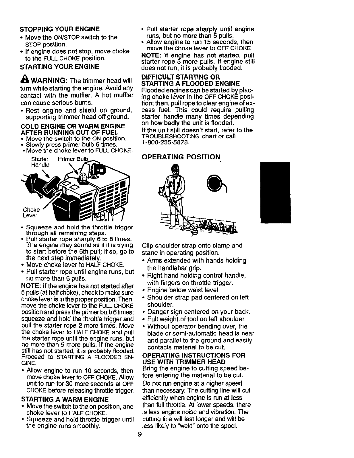
COLD ENGINE OR WARM ENGINE
AFTER RUNNING OUT OF FUEL
• Move the switch to the ON position.
• Slowly press primer bulb 6 times.
• Move the choke lever to FULLCHOKE.
Starter
Handle \
• Pull starter rope sharply until engine
runs, but no more than 5 pulls.
• Allow engine to run 15 seconds, then
move the choke lever to OFF CHOKE
NOTE: If engine has not started, pull
starter rope 5 more pulls. If engine still
does not run, it is probably flooded.
DIFFICULT STARTING OR
STARTING A FLOODED ENGINE
Flooded engines can be started by plac-
ing choke lever inthe OFF CHOKE posi-
tion; then, pull ropeto clear engine of ex-
cess fuel. This could require pulling
starter handle many times depending
on how badly the unit is flooded.
Ifthe unit still doesn't start, refer to the
"TROUBLESHOOTINGchart or call
1-800-235-5878.
OPERATING POSITION
Choke
Lever
• Squeeze and hold the throttle trigger
through all remaining steps.
• Pull starter rope sharply 6 to 8 times.
The engine may sound as if it is trying
to start before the 6th pull; if so, go to
the next step immediately.
• Move choke lever to HALF CHOKE.
• Pull starter rope until engine runs, but
no more than 6 pulis.
NOTE: If the engine has not started after
5 pulls (at half choke), checkto make sure
choke lever is in the proper position. Then,
move the choke lever to the FULLCHOKE
position and press the primer bulb 6times;
squeeze and hold the throttle trigger and
pull the starter rope 2 more times. Move
the choke lever to HALF CHOKE and pull
the starter rope until the engine runs, but
no more than 5 more pulls. If the engine
still has not started, it is probably flooded.
Proceed to STARTING A FLOODED EN-
GINE.
• Allow engine to run 10 seconds, then
move choke lever to OFFCHOKE.Allow
unit to run for 30 more seconds at OFF
CHOKE before releasing throttle trigger.
STARTING A WARM ENGINE
• Move the switchtothe on position, and
choke lever to HALFCHOKE.
• Squeeze and hold throttle trigger until
the engine runs smoothly.
Clip shoulder strap onto clamp and
stand in operating position.
• Arms extended with hands holding
the handlebar grip.
• Right hand holding control handle,
with fingers on throttle trigger.
• Engine below waist level.
• Shoulder strap pad centered on left
shoulder.
• Danger sign centered on your back.
• Full weight of tool on left shoulder.
• Without operator bending over, the
blade or semi-automatic head is near
and parallel to the ground and easily
contacts material to be cut.
OPERATING INSTRUCTIONS FOR
USE WITH TRIMMER HEAD
Bring the engine to cutting speed be-
fore entering the material to be cut.
Do not run engine at a higher speed
than necessary. The cutting line will cut
efficiently when engine is run at less
than full throttle. At lower speeds, there
is less engine noise and vibration. The
cutting line will last longer and will be
less likely to '_veld" onto the spool.
9
If the trimmer head does not turn when
the engine is in operation, make sure
the drive shaft housing is properly
seated in engine shroud.
Always release the throttle trigger and
allow the engine to return to idle speed
when not cutting.
To stop engine:
• Release the throttle trigger.
• Move the ON/STOP switch to the
STOP position.
• If engine does not stop, move choke
to the FULL CHOKE position.
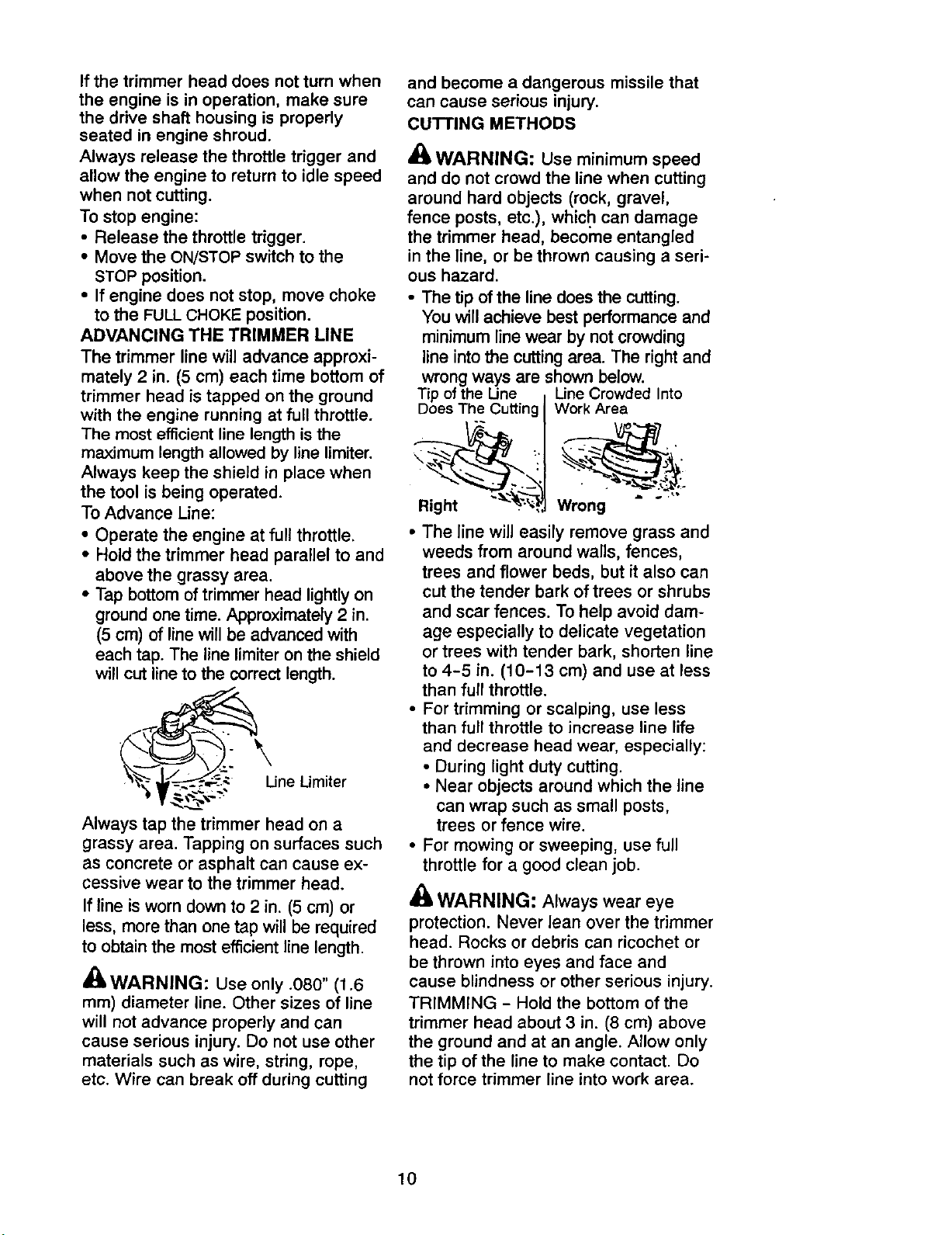
ADVANCING THE TRIMMER LINE
The trimmer line will advance approxi-
mately 2 in. (5 cm) each time bottom of
trimmer head is tapped on the ground
with the engine running at full throttle.
The most efficient line length is the
maximum length allowed by line limiter.
Always keep the shield in place when
the tool is being operated.
To Advance Line:
• Operate the engine at full throttle.
• Hold the trimmer head parallel to and
above the grassy area.
• Tap bottom of trimmer head lightly on
ground one time. Approximately 2 in.
(5 cm) of line will be advanced with
each tap. The line limiter on the shield
will cut line to the correct length.
• /_.
he_v_-_-_,_'- _ Limiter
Always tap the trimmer head on a
grassy area. Tapping on surfaces such
as concrete or asphalt can cause ex-
cessive wear to the trimmer head.
If line is worn down to 2 in. (5 cm) or
less, more than one tap will be required
to obtain the most efficient line length.
_ WARNING: Use only .080" (1.6
mm) diameter line. Other sizes of line
will not advance properly and can
cause serious injury. Do not use other
materials such as wire, string, rope,
etc. Wire can break off during cutting
and become a dangerous missile that
can cause serious injury.
cu'rrlNG METHODS
WARNING: Use minimum speed
and do not crowd the line when cutting
around hard objects (rock, gravel,
fence posts, etc.), which can damage
the trimmer head, becorne entangled
in the line, or be thrown causing a seri-
ous hazard.
• The tip of the line does the cutting.
You will achieve best performance and
minimum line wear by not crowding
line into the cutting area. The right and
wrong ways are shown below.
Tip of the Une Line Crowded Into
Does The Cutting
Right __
Work Area
• . _._o
Wrong
• The line will easily remove grass and
weeds from around walls, fences,
trees and flower beds, but it also can
cut the tender bark of trees or shrubs
and scar fences. To help avoid dam-
age especially to delicate vegetation
or trees with tender bark, shorten line
to 4-5 in. (10-13 cm) and use at less
than full throttle.
• For trimming or scalping, use less
than full throttle to increase line life
and decrease head wear, especially:
• During light duty cutting.
• Near objects around which the line
can wrap such as small posts,
trees or fence wire.
• For mowing or sweeping, use full
throttle for a good clean job.
WARNING: Always wear eye
protection. Never lean over the trimmer
head. Rocks or debris can ricochet or
be thrown into eyes and face and
cause blindness or other serious injury.
TRIMMING - Hold the bottom of the
trimmer head about 3 in. (8 cm) above
the ground and at an angle. Allow only
the tip of the line to make contact• Do
not force trimmer line into work area.
10
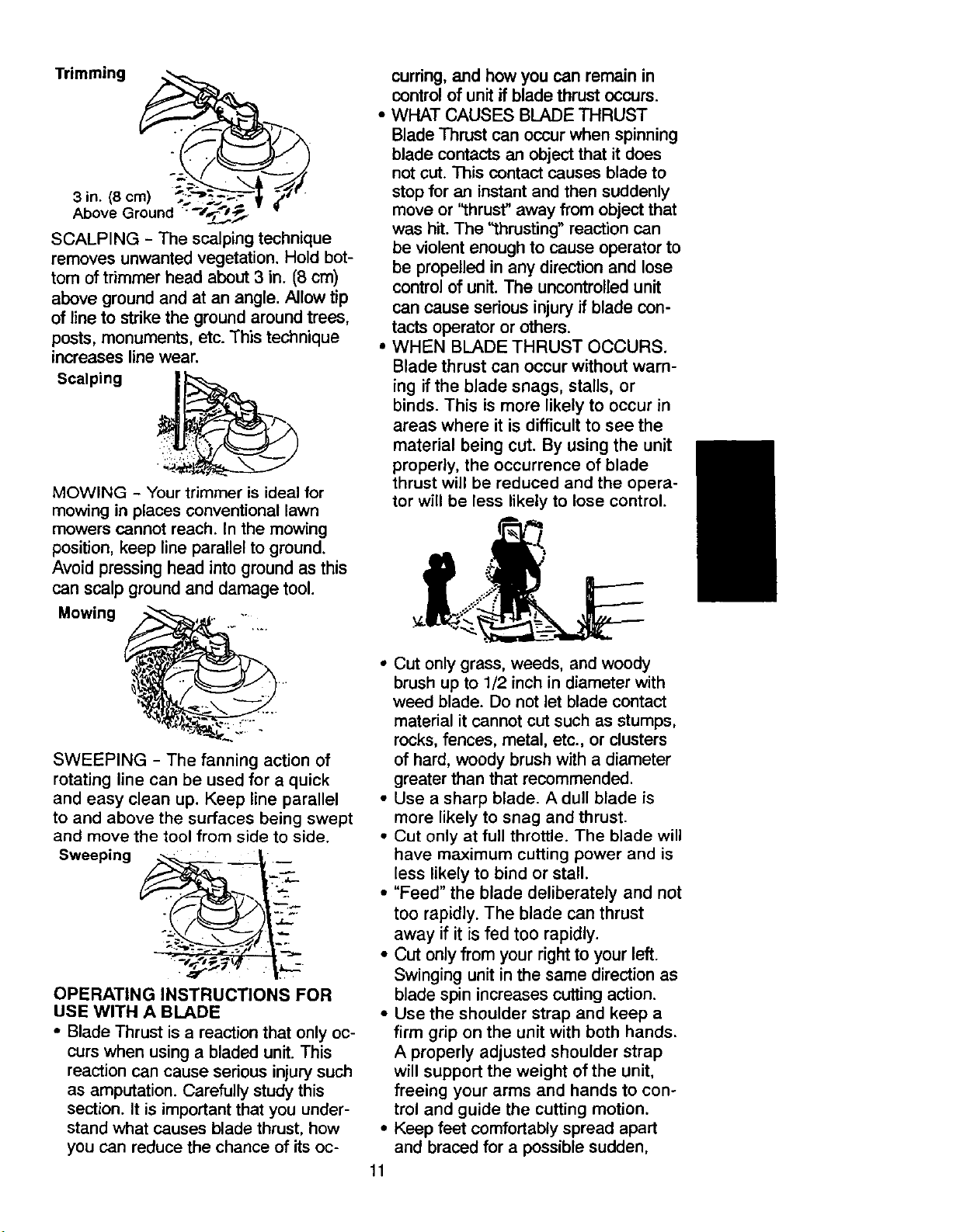
SCALPING - The scalping technique
removes unwanted vegetation. Hold bot-
tom of trimmer head about 3 in. (8 cm)
above ground and at an angle. Allow tip
of line to strike the ground around trees,
posts, monuments, etc. This technique
increases line wear.
Scalping
MOWING - Your trimmer is ideal for
mowing in places conventional lawn
mowers cannot reach. In the mowing
position, keep line parallel to ground.
Avoid pressing head into ground as this
can scalp ground and damage tool.
Mowing
curring,and how you can remain in
control of unit if blade thrust occurs.
• WHAT CAUSES BLADE THRUST
Blade Thrust can occurwhen spinning
blade contacts an object that itdoes
not cut. This contactcauses blade to
stopfor an instant and then suddenly
move or "thrust" away from object that
was hit.The '_hrusting" reaction can
be violent enough to cause operator to
be propelled in any direction and lose
controlof unit. The uncontrolledunit
can cause serious injury if blade con-
tacts operator or others.
• WHEN BLADE THRUST OCCURS.
Blade thrust can occur without warn-
ing if the blade snags, stalls, or
binds. This is more likely to occur in
areas where it is difficult to see the
material being cut. By using the unit
properly, the occurrence of blade
thrust will be reduced and the opera-
tor will be less likely to lose control.
SWEEPING - The fanning action of
rotating line can be used for a quick
and easy clean up. Keep line parallel
to and above the surfaces being swept
and move the tool from side to side.
Sweeping __,.._..,
OPERATING INSTRUCTIONS FOR
USE WITH A BLADE
• Blade Thrust is a reaction that only oc-
curs when using a bladed unit. This
reaction can cause serious injury such
as amputation. Carefully study this
section. It is important that you under-
stand what causes blade thrust, how
you can reduce the chance of its oc-
• Cut only grass, weeds, and woody
brush up to 1/2 inch in diameter with
weed blade. Do not let blade contact
material it cannot cut such as stumps,
rocks, fences, metal, etc., or clusters
of hard, woody brush with a diameter
greater than that recommended.
• Use a sharp blade. A dull blade is
more likely to snag and thrust.
• Cut only at full throttle. The blade will
have maximum cutting power and is
less likely to bind or stall.
• "Feed" the blade deliberately and not
too rapidly. The blade can thrust
away if it is fed too rapidly.
• CUt only from your right to your left.
Swinging unit in the same direction as
blade spin increases cutting action.
• Use the shoulder strap and keep a
firm grip on the unit with both hands.
A properly adjusted shoulder strap
will support the weight of the unit,
freeing your arms and hands to con-
trol and guide the cutting motion.
Keep feet comfortably spread apart
and braced for a possible sudden,
11
rapid thrustof unit. Do not overreach.
Keep firm footing and balance.
• Keep blade below waist level. It will
be easier to maintain control of unit.
• Do not raise the engine above your
waist as the blade can come danger-
ously close to your body.
• Do not swing the unit with such force
that you are in danger of losing your
balance.
Bring the engine to cutting speed be-
fore entering the material to be cut.
Ifthe blade does not turn when you
squeeze the throttle trigger, make sure
the tube is fully inserted into engine.
Always release the throttle trigger and
allow engine to return to idle speed
when not cutting. The blade should not
turn while the engine is running at idle.
If the blade turns at idle, do not use
your unit. Refer to the Carburetor ad-
justment section or contact your Sears
Service Center.
• Maintain good firm footing while us-
ing the unit. Do this by planting feet
firmly in a comfortable apart position.
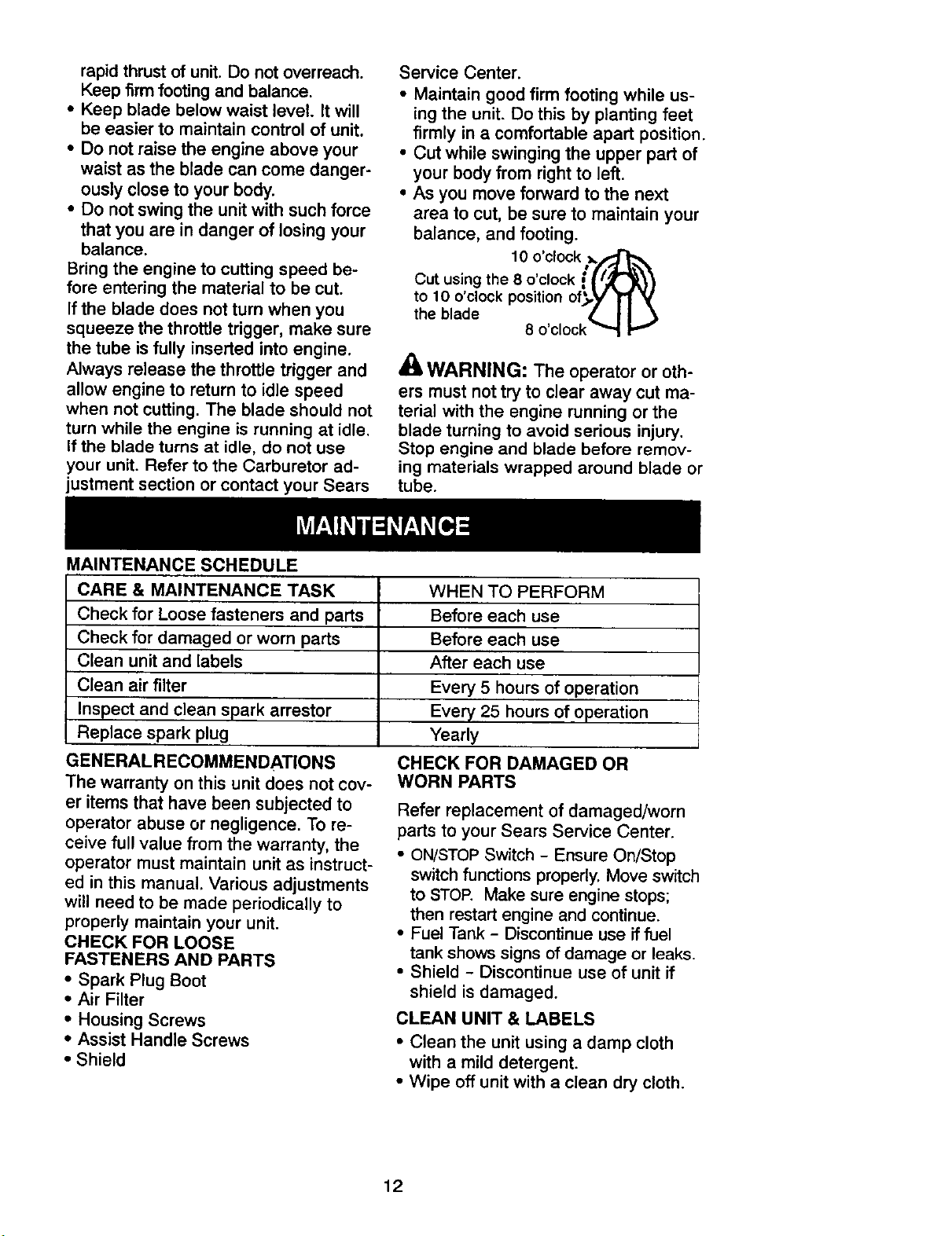
• Cut while swinging the upper part of
your body from right to left.
• As you move forward to the next
area to cut, be sure to maintain your
balance, and footing.
10 o'clock _/_
Cut using the 8 o clock ={ i_r_}
to lO o clock position of_,y _'1 _'
the blade • I I
8 o'clock _
WARNING: The operator or oth-
ers must not try to clear away cut ma-
terial with the engine running or the
blade turning to avoid serious injury.
Stop engine and blade before remov-
ing materials wrapped around blade or
tube.
MAINTENANCE SCHEDULE
CARE & MAINTENANCE TASK
Check for Loose fasteners and parts
Check for damaged or worn parts
Clean unit and labels
Clean air filter
Inspect and clean spark arrestor
Replace spark plug
GENERALRECOMMENDATIONS
The warranty on this unit does not cov-
er items that have been subjected to
operator abuse or negligence. To re-
ceive full value from the warranty, the
operator must maintain unit as instruct-
ed in this manual. Various adjustments
will need to be made periodically to
properly maintain your unit.
CHECK FOR LOOSE
FASTENERS AND PARTS
• Spark Plug Boot
• Air Filter
• Housing Screws
• Assist Handle Screws
• Shield
WHEN TO PERFORM
Before each use
Before each use
After each use
Every 5 hours of operation
Every 25 hours of operation
Yearly
CHECK FOR DAMAGED OR
WORN PARTS
Refer replacement of damaged/worn
parts to your Sears Service Center.
• ON/STOPSwitch - Ensure On/Stop
switch functions properly. Move switch
to STOP. Make sure engine stops;
then restart engine and continue.
• Fuel Tank - Discontinue use if fuel
tank shows signs of damage or leaks.
• Shield - Discontinue use of unit if
shield is damaged.
CLEAN UNIT & LABELS
• Clean the unit using a damp cloth
with a mild detergent.
• Wipe off unit with a clean dry cloth.
12
 Loading...