

Craftsman 358353660, 358353670, 358353690 Owner’s Manual
[Sears
owner's
manual
• Assembly
• Operation
• Maintenance
• Repair Parts
VlODEL NO.
58.353660-2.3/14"
358.353670-2.3/16"
358.353690-2.3/16"PS
WARNING:
Carefully read and follow
Safety Rules, Precautions
and Operating Instruc-
tions. Failure to do so can
result in serious personal
injury.
CRRFTSMRH
2.3/14" Z3/16" 2.3/16"PS.
GASOLINE CHAINSAWS
THIS CHA! N SAW IS FOR OCCASIONAL USE ONLY.
Record in the space provided below the Model No. and Serial No. o{
your saw. These numbers are located on the starting instructions
decal.
Model No. Serial No.
Retain these numbers for future reference.
64765-3-06183- t -06283
S(_L, s, Ro(_buck _nd C.o., Chic_o_), Ill. 60.684 U.S.A.
PRINTED IN U. S. A.
FULL ONE YEAR WARRANTY ON GASOLINE CHAIN SAW
(Excluding Bar, Chain, Spark Plug, Air Filter and Starter Rope)
For one year from date of purchase, when you maintain, lubricate, and tune up this chain saw according to the operating _
and maintenance instructions in the owner's manual, Sears will repair defects in material or workmanship in this gasoline
chain saw at no charge.
This warranty excludes the bar, chain, spark plug, air filter, and starter rope which are expendable parts and become worn
If this chain saw is used for commercial or rental purposes, this warranty applies for only 30 days from date of purchase.
WARRANTY SERVICE IS AVAILABLE BY RETURNING THE CHAIN SAW TO THE NEAREST SEARS STORE OR SERVICE
during normal use.
• CENTER IN THE UNITED STATES.
T_is warranty gives you specific legal rights; and you,may also have other rights which vary from state to state. . ._
• , " ( f e .... "- .... "
Sears,RoebuckandCo.,SearsTower, Dept. 698/731A, Chicago,IL 60684 -
TABLE OF CONTENTS
Specifications .............................. 2 Using the Power Sharp System ................ 12
Safety Rules and Precautions ..... . ............ 3 Types of Cutting ............................. 13
Know Your Chain Saw ........................ 4 A..Basic Cutting Technique .................. 13
A. IntroduCtion ........................... 4 B. Tree Felling Techniques :.' ............... 14
B. State and Local Ordinance Requirements... 4 C. Bucking .................. ............. ".15
C. CartGi]C0ntents ................... ..... 4 . ' :,D. Debranching and Pruning ..... :..... :. .... 16
Preparing Your Saw For Use ........... .......... 5 Maintenance . _... .. ......... ................ 17
A. Getting" Ready .......................... 5
B. Attaching the Handguard .... ............ 5
C. Attaching the Bar and Chain. _,.. : ...... ... 5
D. Chain Tension .................. : ....... 7
E. Engine Fuel Mixture .................. :... 8
F. Barand Chain Oi1 .................. _.... 9
G. Optional Muffler Heat Shield Assembly :... 9
Using Your Unit ............................. 10
A. Pre-Operation Checks ................... 10
B. Starting Instructions .................. .. 10
C. Controlling Kickback .................... 11
A. Guide Barand Chain ............ , ....... 17
B. Ignition, Cooling, and Exhaust Systems .... 19
C. Starter Rope Repairand Replacement ...... 19
D. Carburetor Adjustments .................. 21
E. Air Filter .............................. 22
F. Storage ............................... 22
G. Maintenance Accessories...: ; ............ 23
H. Troubleshooting Chart .................. 24
Repair Parts ................................. 26
Quick Reference Page ........................ 31
Ignition Switch
Rear Handle
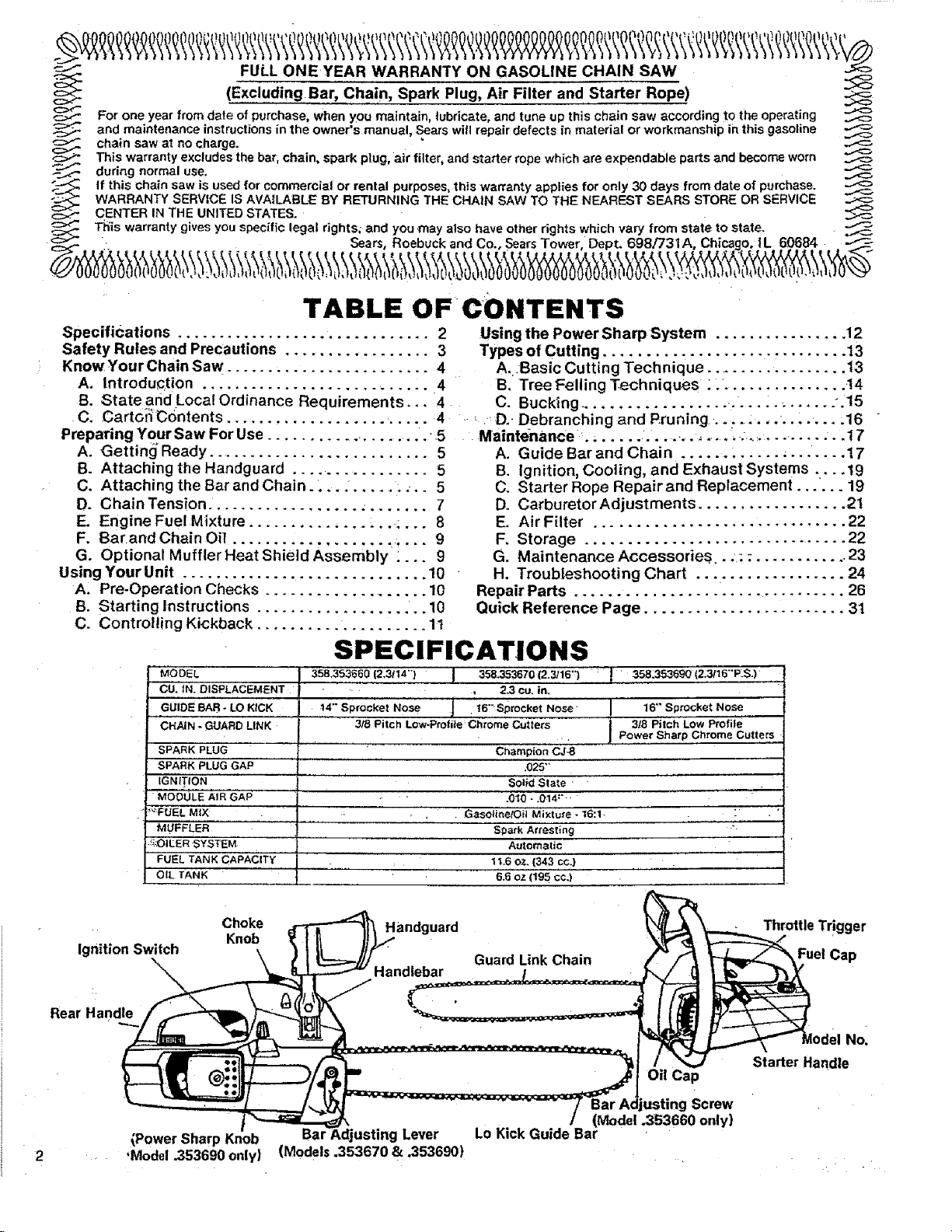
SPECIFICATIONS
MODEL 358.353660 12,3114") I 358.353670 (2.3116")
CU.'IN_ DISPLACEMENT ': .... , 2.3 cu. in. ' '
,ii ............ i
,GUIDE BAR- LO KICK ......................:,,,i_,4,:"Sprocket Nose 16""Sprocket Nose
CHAIN - GUARD LINK 3/8 Pitch Low-Ptoffie Ch_,ome Cutters
SPARK PLUG ..... " Champion'CJ-8
SPARK PLUG GAP 025""
IGNITION ' ' ' Solid State • '........
MODULE AIR GAP - ' ' .010 - ,0t4:" '....
_FUEL MIX Gasoth_elOil Mixt'u'r ,_ - t6:1- '
MUFFLER Spa_k Arresting '-
:_OIILER 'SYSTEI_: ..... Automatic ' '
FUEL TANK CAPACITY ...... 11.6 OZ. (343 CC.)
O'IL TANK ' " "......... 6,5 oz (t95 C¢,i .....
Choke Handguard
Knob
: I, 358:353e90 (2:3116"'PLS.)
"" 16" Sp_cket Nose
318 Piich' LOW Profiie '
Po,wer Sharp Chrome Cutters
ThrottleTrigger
Starter Handle
Oil Cap
Fuel Cap
No_
(Power Sharp Knob
,Model .353690 only)
Bal Lever
(Models °353670 & .353690)
Lo Kick Guide Ba_rM°del"
usting Screw
.353660 only}
SAFETY RULES AND PRECAUTIONS
-- WARNING! ]
Failure to observe the following Safety Rules andl
Precautions could result ,n serious personal injury. J
A. KNOW YOUR SAW
t. Read your Owner's Manual carefully until you
completely understand and can apply all safe-
ty rules and operating instructions before at.
.tempting to operate the unit.
2. Restdct Lthe use of your saw to users who
understand and follow all safety rules,
precautions, and operating instructions found
in this manual.
B. PLAN AHEAD
%' Wear personal protective gear.
Always use safety f0otwear;
snug-f!tting c|othing; protective
gloves; and appropriate eye,
hearing and head protectiondevices,
2-, Keep children, bystanders, and pets out of the
work area. Do not allow other people to be
near the chain saw when starting or operating
the chain saw.
3. Do not handle or operate a chain saw when
you are tired, ill or upset: or if you have taken
alcohol or drugs/medication. You must be in
good physical condition and mentally alert.
4. Do not attempt to use your saw during
bad weather conditions such as strong wind,
rain, snow, etc., or at night since you would
not ha_e :good visibility.
5. Plan yo'ursawing operation carefully in ad.
vance; DO not start cutting until you have a
clear work area, secure footing, and a planned
retreat path from the falling tree.
C. HANDLE FUEL WITH CAUTION
__,l;:.l_limJnat e allsources of sparks or flame in the
areas where fuel is mixed, poured, Or stored.
There should be no smoking, open flames, or
:w_ that could cause sparks:
,2. Mix!and store fue! in .a well.ventilated area.
3. Mix and store fuel in an approved, marked
container.
4:.Mo_e at least 10 feet (3 meters) away from
fuel and fueling site before starting the
engine.
5; Do.not smoke while handling fuel or while
Operating the saw.
6. Turn the engine off and let your saw cool
before removing the fuel tank cap and refuel-
ing the unit.
7. Let the saw cool in a non-combustible area,
not on dry leaves, straw, paper, etc.
8. Wipe up all spills, Wipe off fuel spilled on the
saw before using.
D. GUARD AGAINST KICKBACK
Kickback can lead to dangerous loss o f_icon-
trol of the chain saw and possibly cause
serious personal injury. Kickback is the up-
ward and backward motionof the guide bar that
occurs when thesaw chain contacts an object
at the nose of the guide bar. To reduce the
hazard Ofkickback:
1, Hold the chain saw firmly with both hands.
2. Do not overreach.
3. Do not let the nose of the guide bar contact
the ground, ,a log, a :branch_ or any _other
obstruction. ,_
4. Cut only with the engine running at fuli_hrot -
tie.
5. Do not cut above shoulder height.
6. Follow manufacturer, s sharpening and
maintenance instructions for the saw chain.
7. Use the Guard Link Chain and Lo Kick Guide
Bar designed for your saw to help reduce the
possibility of kickback, ,. "° -
E. OPERATE YOUR SAW SAFELY
1. Do not operate a chain saw that is damaged,
improperly adjusted, or not completely and
'securely assembled. _
2. DO not operate the saw from a ladder or in a
tree.
3. Keep all parts of your body awayfrom the saw
chain when the engine is running.
4. Cut wood only.
5, Make sure the saw chain is not touching
anything before you start the engine. :_ _
'6., Use_extreme_cautioq_ when,cutting smal{, size
brush and saplings.; Slender material may
catch the saw chain and be whipped to,ward
you or pull you off balance. ""'
7, Be,alert for springback when cutting a limb
that is under tensionso you will not be struck
by the limb or saw when the tension in the
wood fibers is released.
8. Shut off the engine before setting the saw
down.
MAINTAIN YOUR SAW IN GOOI_
Fw
WORKING ORDER
1. Have all chain saw service performed by your
SEARS Service Center other than the service
described in the maintenance section of this
manual.
2. Keep fuel and oil caps, screws and fasteners
: tight.
3. Keep the handles dry, clean, and free of oil or
fuel mixture.
4. Make certain the saw chain stops moving
when the throttle trigger is released. Refer to
page 21 for carburetor adjustment instruc-
tions if the chain does not stop.
5. Stop the saw if the chain strikes a foreign ob-
ject. inspect the unit and repair or replace
parts as necessary.
GI=
CARRY AND STORE YOUR SAW
SAFELY
1. Never carry your saw while climbing. Both
hands are needed for safe climbing.
2. carry the unit with the engine stopped, the
guide bar and chain to the rear, and the muf-
fler away from your body.
KNOW YOUR CHAIN SAW
°-_3iCarry the saw with_,,guide bar and chain
covered, preferably with an appropriate scab-
bard.
4. Allow your saw to cool completely before
transporting in any vehicle or storing in any
enclosure.
5. Drain oil and fuel tank before storing for more
than 30 days.
6. Store in a dry area outof the reach of children
and away from where fuel vapors can reach
an open flame from hot water heaters; fur-
naces, etc.
A.
INTRODUCTION :.....
The_information found in this manual.will help
you properly prepare your chain saw -for use,
understand how to operate your saw safely, and
perform maintenance required to keep your unit
in top working condition.
Your saw has been designed with safety in mind
and includes the following safety features, as
standard equipment:
Handguard
Lo Kick Guide Bar
Guard Link Chain
The chain saw should never be operated unless
these devices are properly installed on the unit.
The Lo Kick Guide Bar and Guard Link Chain
have been designed to help reduce.the incident
of KICKBACK. You should thoroughly read and
_understand the section, "CONTROLLING
KICKBACK" on page 11 before operating the
saw.
El
STATE AND LOCAL ORDINANCE
REQUIREMENTS
_Your Saw has; been; furnished with an'approved
Spark AFestorScreen which is required in some
areas bylaw. You are legally responsible for see-
ing that the Spark Arrestor is properly main-
tained in these areas. Failure to do so could sub-
ject you to liability or to a fine. See Spark Ar-
restor maintenance, page 19.
Check with your state conservation or forestry
department about regulations concerning oper-
ating your saw on forest, brush, or grass covered
areas. All U.S. forest land and the states of
California, Maine, Washington and Oregon re-
quire many internal combustion engines to be
equipped with a temperature limiting muffler by
law. Such laws require fitting your saw with an
additional muffler heat shield.
A shield which meets these requirements can be
purchased at your Sears Service Center as an
optional accessory kit. Ask for Muffler Heat
Shield Kit, Repair Part No. 69037.
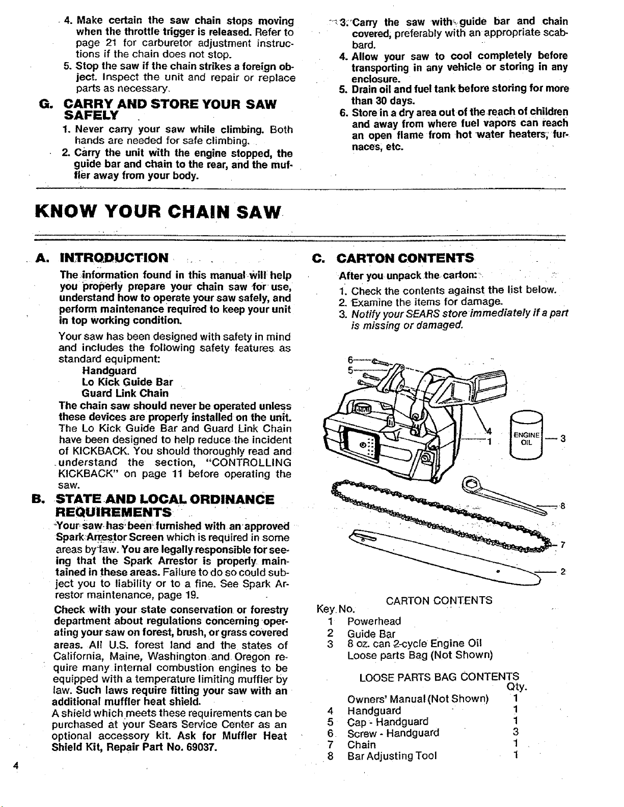
C. CARTONCONTENTS
After you unpack 1he carton:"
1. Check the contents against the list below.
2. Examine the items for damage.
3. Notify your SEARS store immediately if a part
is missing or damaged.
--3
CARTON CONTENTS
Key. No.
1 Powerhead
2 Guide Bar
3 8 oz. can 2-cycle Engine Oil
Loose parts Bag (Not Shown)
LOOSE PARTS BAG CONTENTS
Qty.
Owners' Manual (Not Shown) 1
4 Handguard !
5 Cap- Handguard 1
6 Screw- Handguard 3
7 Chain 1
8 Bar Adjusting Tool 1
PREPARING YOUR SAW FOR USE
A. GETTING READY
1. READ YOUR OWNER'S MANUAL CARE-
FULLY.
Your Owner's Manual has been developed to
help you prepare your saw for use and, to
understand its safe operation. It is important
that you read your manual completely to
become familiar with the unit before you
begin assembly,
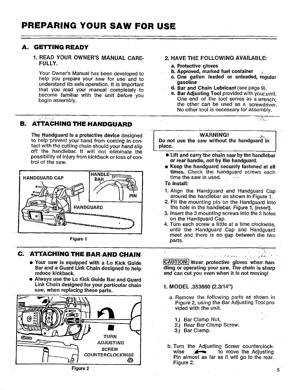
Su ATTACHING THE HANDGUARD
The. ;Ha,ndguardis a,protective device designed
to help°prevent your hand from coming in con-
tact with the cutting chain should your hand slip
off the handlebar. It will not eliminate the
possibilityof injury from kickback or loss of con-
trol of the saw.
HANDGUARD CAP
Figure I
HANDLE-_
illll
U PiN
2. HAVE THE FOLLOWING AVAILABLE:
a. Protective gloves
b. Approved, marked fuel container _...
c. One gallon leaded or unleaded, regular
gasoline
d. Bar, and Chain Lubricant (see page 9).
e. Bar Adjusting Tool provided with your_unit.
One end of the tool serves as a wrench;
the other can be used as a screwdriver.
No other too! is necessary for assembly.
Do not usethe saw.without the handguar_!':in
place.
.... ;WARNING! ' --,. t
• Lift and carry the chain sawby the handlebar
or rear handle, not by the handguard:
• Keep the handguard securely fastened at all
times. Check the handguard screws each
time the saw is used ......
To install:
1. Align the Handguard and Handguard Cap
around the handlebar as shown in Figure 1.
2. Fit the mounting pinch the Handguard into
the hole in the handlebar. Figure 1, (insert).
3. Insert the 3 mounting screws into the3 holes
on the Handguard Cap.
4. Turn each screw a little at a time clockwise,
until the Handguard Cap and Handguard
meet and there is no 'gap between the two
parts.
C, Alr_,ACHiNG_THE BAR,AND CHAIN,
• Your_saw is equipped with'a Lo Kick Guide
Barand.a Guard Link Chain designed to help
reduce kickback,
• Always.use .the Lo Kick-Guide Bar and Guard
Link Chain designed for your particular chain
saw, when replacing lhese pads,
TURN
ADJUSTING
SCREW
COUNTE RCLOCKW
Figure 2
•ICAu]:ION-'twear protectivegloves_wSemhan.
dling or operating your saw..The chain is; sharp
and can cut you even when it is not moving!
1. MODEL .353660 (2.3/i4")
a. Remove the following parts as sho:v_n in
Figure 2, using the Bar Adjusting Tool pro-
vided with the unit.
1.) Bar Clamp Nut.
2.) Rear Bar Clamp Screw.
3.) Bar Clamp.
b. Turn the Adjusting Screw counterclock-
wise _ to move the Adjusting
Pin almost as far as it will go to the rear.
Figure 2.
5
CLUTCH '
CLUTCH
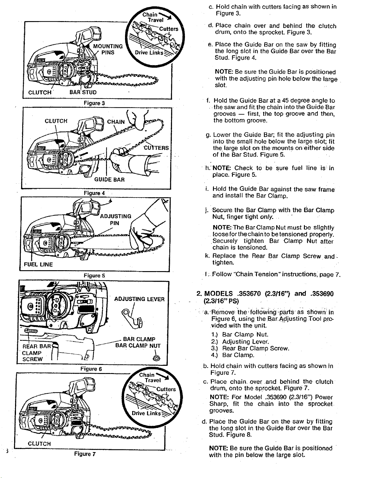
Figure 3
c. Hold chain with cutters facing as shown in
Figure 3.
d. Place chain over and behind the clutch
drum, onto the sprocket. Figure 3.
e. Place the Guide Bar on the saw by fitting
the long slot in the Guide Bar over the Bar
Stud. Figure 4.
NOTE: Be sure the Guide Bar is positioned
with the adjusting pin hole below the large
slot.
f. Hold the Guide Bar at a 45 degree angle to
the saw and fi[the chain into the GuideBar
grooves -- first, the top groove and then,
the bottom groove.
g. Lower the Guide Bar; fit the adjusting pin
into the small hole below the large slot; fit
the large slot on themounts on either side
of the Bar Stud. Figure 5.
• h/NOTE: Check tO be sure fuel line is _in
place. Figure 5.
•CLAMP
SCREW
Figure 4 :
Figure 5
ADJUSTING LEVER
_BAR CLAMP
Figure 6
R CLAMP NUT
\
L Hold the Guide Bar against the saw frame
and install the Bar Clamp.
j. Secure the Bar Clamp with the Bar Clamp
Nut, finger tight only..
NOTE: The Bar Ctamp Nut must be slightly
loose for the chain to be tensioned properly.
Securely tighten Bar Clamp Nut after
chain is tensioned.
k. Replace the Rear Bar Clamp Screw and,
tighten.
I: Follow "ChainTension" instructionsl page 7.
2. MODELS .353670 (2.3116") and .353690
(2.3116" PS)
,: a ._Remove :the ;foilowing :parts. as shown!in
Figure 6, using the.Ba[._djusting Tool pro-
.vided with the unit.
1.) Bar Clamp Nut.
2.) Adjusting Lever.
3.) Rear Bar Clamp Screw.
4.) Bar Clamp.
b. Hold chain with cutters facing as shown in
Figure 7.
c. Place chain over and behind the clutch
drum, onto the sprocket. Figure 7.
NOTE: For Model 353690 (2.3!16") Power
Sharp, fit the chain into the sprocket
g rooves.
CLUTCH
Figure 7
d. Place the Guide Bar on the saw by fitting
the long slot in the Guide Bar over the Bar
Stud, Figure 8.
NOTE: Be sure the Guide Bar is positioned
with the pin below the large slot.

e. HoldtheGuideBarat a 45 degree angle to
the saw and slip the chain into the Guide
Bar grooves -- first, the top groove and
then, the bottom groove. Figure 8.
f. Lower the Guide Bar; fit the large slot on
the mounts on either side of the Bar Stud;
and slide the Guide Bar. forward.
NOTE: Check to be sure fuel line is in
place: Figure 8.
g. Hold the Guide Bar againsi thesaw frame
and install the Bar Clamp.
h. Place the Adjusting Lever and the Bar
Clamp on the Bar Stud. Figure 9.
;NOTE: Be sure the adjusting lever is posi-
tionedbehind the pin in the bar.
i. Tighten the Bar Clamp Nut, finger tight
only.
NOTE: The Bar C_amp Nut must be left
slightly loose for the chain to be tensioned
properly. Tighten Bar Clamp Nut securely
after chain is tensioned.
Jj. Replace the RearBar Clamp Screw and
tighten securely.
k. Follow 'Chain Tens'on "nstructionsbelow: .....
__ADJUSTING
e.e
CUTTERS
Figure 8
'ADJUSTING LEVER
Figure 9
BAR
,
_IN
D. CHAIN TENSION
• Chain tension is very important:.
--a loose chain wi!t wear the bar and itself.
--a loose chain can jump off the bar while
you are cutting.
--a tight chain can damage the saw and/or
break.
--a:chain, either too loose or too tight, can
cause injury.
• Chain tension is correct when thechain:
:_can be lifted aboutll8'_ from the Guide Bar
at a point near the middle of_the bar, and
• _ --will move freely around the bar.
• The chain stretches during use, especially
::_;when new. Check tension:
,--Each:time the: saw is used
• _.'_:'i,i'_More frequentlyl when thechain is new
,,,,,
• The Bar Clamp Nut _must be slightly loose for
the chain to be propedy tensioned.
]CAUTION_Always wear gloves when handling
the chain. The chain is sharp and can cut you
even when it is not moving!
1, MODEL .353660 (2.3/14")
ao Hold the tip of the Guide Bar up and turn
the Adjusting Screw clockwise just until
the chain does not sag beneath the Guide
Bar. Figure 10.
b. Check the tension by lifting the chain from
- 1he.Guide Bar at the center of_;the bar.
Figure 11. .'.
.... c;.Continue adjusting the, Adjustii_g Screw
until:tlle tension :is correct.
d. Hold the tipof theGuide Bar up and tighten
the Bar Clamp Nut with the Bar Adjusting
Tool.
e. Check the Rear Bar Clamp Screw-to be sure
it is secure.
f. Recheck chain tension.
CH,,NCANBE
LIFTED 1t8" WHEN
TENSION IS
TURN
TO LOOSEN
TENSION
1t8"
Figure 10 Figure "11
L. i i'
7
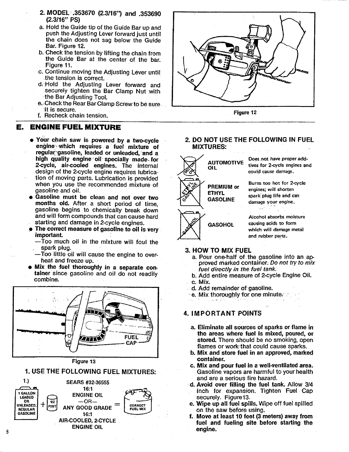
2. MODEL.353670 (2.3/16") and .353690
(2.3/16" PS)
a. Hold the Guide tip of the Guide Bar up and
push the Adjusting Lever forward just until
the chain does not sag below the Guide
Bar. Figure 12.
b. Check the tension by lifting the chain from
the Guide Bar at the center of the bar.
Figure 11.
c, Continue moving the Adjusting Lever until
the tension is correct.
d, Hold the Adjusting Lever forward and
securely tighten the Bar Clamp Nut with
'the Bar Adjusting Tool.
e.,CheCk the Rear Bar Clamp Screw to be suie
it is secure.
f. Recheck chain tension.
E. ENGINE FUEL MIXTURE
Figure 12
• Ydur chain saw is powered by a two-cycle
engine?-Which requires a fuel mixture of
regula_gasoline, leaded or unleaded,'and a
high ,quality engine, oil- specially made- for
2-cycle, air-cooled engines. The internal
design of the 2-cycle engine requires lubrica-
tion of moving parts. Lubrication is provided
when you use the recommended mixture of
gasoline and oil,
• Gasoline must be clean and not over two
months old. After a short period of time,
gasoline begins to chemically break down
and wil! form compounds that can cause hard
starting and damage in 2-cycle engines.
• The correct measure of gasoline to oil is very
importanL
--Too much oil in the mixture will foul the
spark plug.
--Too little oil will cause the engine to over-
heat and freeze up.
• Mix the ,fuel thoroughly in a separate con-
tainer since gasoline and oil do not readily
combine,
2. DO NOT USE THEFOLLOWING IN FUEL
MIXTURES:
Does not have properadd-
OIL
AUTOMOTIVE
tires for 2-cycleenginesand
couldcausedamage.
BurnStoo hot for 2*_'ycle
ETHYL
_ REMIUM or
_ GASOHOL
GASOLINE
engines; will shorten
spark plug life andcan
damage your engine.
Alcohol absorbs moisture
causing acids to form
which will damage meta|
and nlbber pa.rts.
3..owTo.IXFUEL
a. Pour one-half Of.the gasoline into an ap-
proved marked container; Do not try to mix
fuel directly in the fuel tank.
b. Add entire measure of 2-cycle Engine Oil.
c. Mix.
d. Add, remainder of gasoline.
,-e. Mix thoroughly'for one minute,: • '
. o
Figure 13
1. USE THE FOLLOWING FUEL MIXTURES:
i.) SEARS #32-36555
ENGINE OIL
--OR-
+ ANY GOOD GRADE --
16:1
AIR*COOLED, 2-CYCLE
ENGINE OIL
4. IMPORTANT POINTS
a. Eliminate all sources of sparks or flame in
the areas where fuel is mixed, poured, or
stored. There should be no smoking, open
flames or work_that could cause sparks.
b, Mix and store fuel in an approved, marked
container.
c. Mix and-pour fuel in a well.ventilated area.
Gasoline vapors are harmful to your health
and are a serious fire hazard.
Avoid over filling the fuel tank. Al!ow 3/4
.d.
inch for expansion. Tighten Fuel Cap
securely. Figure13.
e. Wipe up all fuel spills. Wipe off fuei spilled
on the saw before using_
f.. Move at least 10 feet (3 meters) away from
fuel and fueling site before starting the
engine.
F!
BAR AND CHAIN OIL
• The guide bar and cutting chain require con-
stant lubrication in order to remain in
operating condition, Lubrication is provided
by the automatic oiler system when the oil
tank is kept filled.
--Lack of oil will quickly ruin the bar and
chain,
--Too little oil will cause overheating shown
,by smoke coming from the chain andJor
,discoloration of the guide bar rails.
e Use SEARS Bar and Chain Lubricant #36554
or clean SAE 3OW oil,
• o' InTfreezing weather oil will thicken, making it
._°-_h_b_e:ssaryto thin barand chain oil with a
small amount of Diesel Fuel #1 or Kerosene.
Bar and chain oit must be free flowing for the
oil system to pump enough oil for adequate
lubrication.
1__E THE FOLLOWING:
30°F or above--Lubricant--undiluted.
30°F- 0°F --95% Lubricant to
, ,_;.!_'_,:_ 5% Diesel Fuel #1
or Kerosene.
Below 0°F --90% Lubricant to
10% Diesel Fuel #1
or Kerosene.
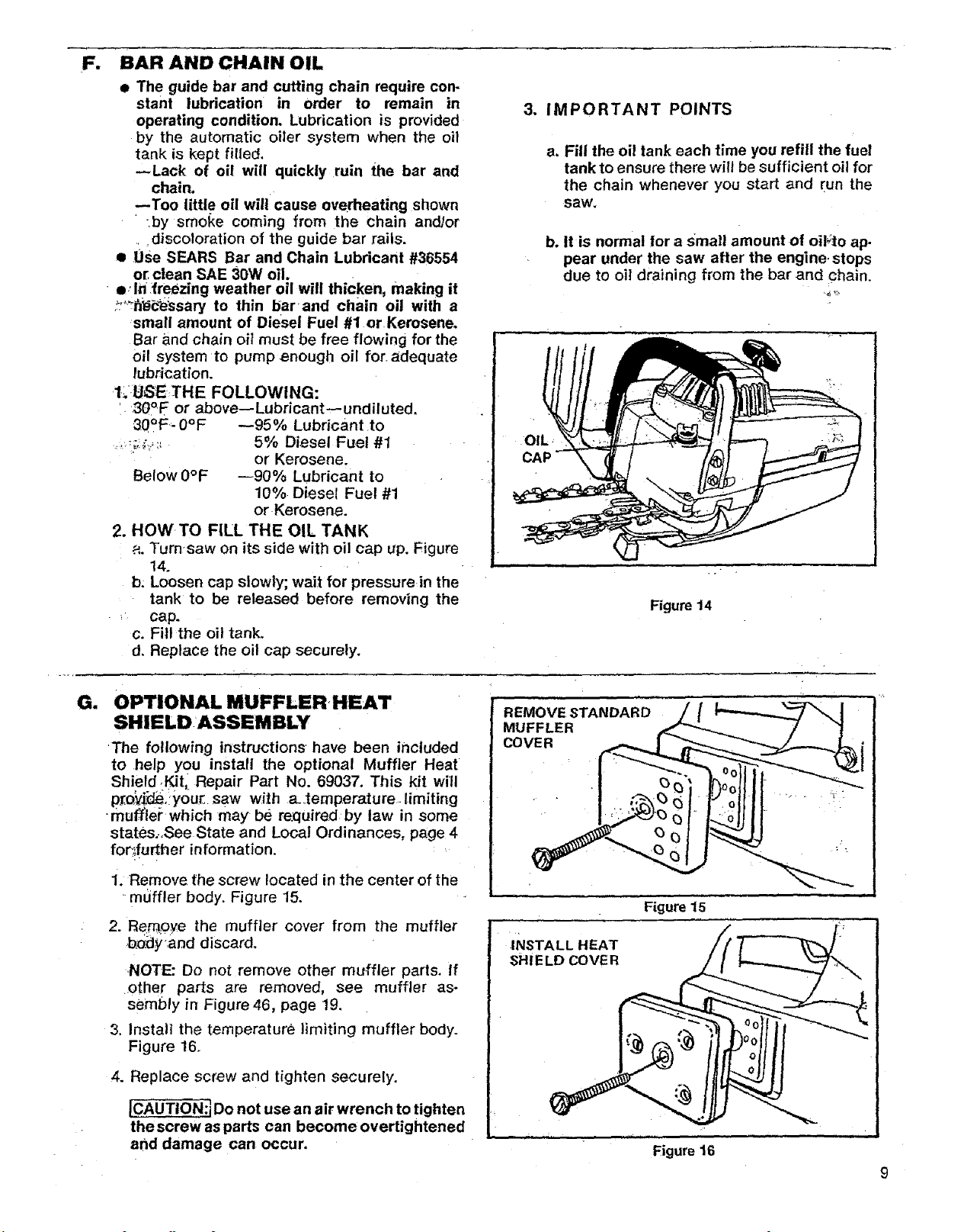
2. HOWTO FILL THE OIL TANK
a. Turn-saw on its side with oil cap up. Figure
14.
b. Loosen cap slowly; wait for pressure,in the
tank to be released before removing the
: cap.
c. Fill the oil tank,
d. Replace the oil cap securely,
3. IMPORTANT POINTS
a. Fill the oil tank each time you refill the fuel
tank to ensure there will be sufficient oil for
the chain whenever you start and Fun the
saw.
b, it is normal for a Small amount of oil;to ap-
pear under the saw after the engine, stops
due to oil draining from the bar and _hain.
OIL •
CAP
Figure 14
Gm
OPTIONAL MUFFLER, HEAT
SHIELD:ASSEMBLY
•The following instructions have been included
to help you install the optional Muffler Heat
Shield ,Kit,_Repair Part No. 69037. This kit will
pf.o_(_, you_ saw with a_temperatureolimiting
•muffle/" which may be re:quired by law in some
states;,See State and Local Ordinances, page 4
for_further information.
1. Remove the screw located in the center of the
-muffler body. Figure 15.
2. Rem_o_e the muffler cover from the muffler
b_dy'and discard.
NOTE: Do not remove other muffler parts. If
.other parts are removed, see muffler as*
sembly in Figure 46, page 19.
3. Install the temperature limiting muffler body.
Figure 16.
4. Replace screw and tighten securely.
JCAUTION:i Do not use an air wrench to tighten
the screw as parts can become overtightened
and damage can occur,
REMOVE STANDARD
MUFFLER
F{gure 15
INSTALL HEAT
sH iE LD COVE R
i i
Figure 16
9
USING YOUR SAW
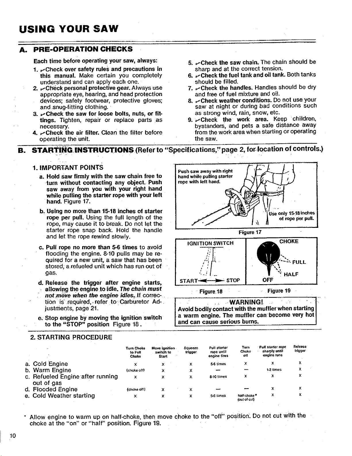
A. PRE-OPERATION CHECKS
Each time before operating your saw, always:
1. vCheck over safety rules and precautions in
this manual. Make certain you completely
understand "and can apply each one.
2. ,,-Check personal protective gear. Always use
appropriate eye, hearing, and head protection
devices; safety footwear, protective gloves;
and snug-fitting clothing.
3. ,,-Check the saw for loose bolts, nuts, or fit-
tings. Tighten, repair or replace parts as
necessary.
4. ,.-Check the air filter. Clean the filter before
operating the unit.
STARTING INSTRUCTIONS (Refer to
BE
1. IMPORTANT POINTS
a. Hold saw firmly with the saw chain free to
turn without contacting any objecL Push
saw away from you with your right hand
whilepulling the starter rope with your left
hand. Figure 17.
b. Using no more than 15-18 inches of starter
rope per pull. Using the full length of the
rope, may cause it to break. Do not let the
starter rope snap back. Hold the handle
and let the rope rewind slowly.
C*
Pull rope no more than 5-6 times to avoid
flooding the engine. 8-10 pulls may be re-
quired for a new unit, a saw that has been
stored; a refueled unit which has run out of
gas.
d. Release the trigger after engine starts,
allowing the engine to idle. The chain must
• not.mo_e when .the engine idles, Jfcormc-
ti0n is_required,, refer to':Carburetor Ad.
justr_ents, page 21.
e. Stop engine by moving the ignition switch
to the "STOP" position Figure 18.
5. ,.-Check the saw chain. The chain should be
sharp and at the correct tension.
6. ,..Check the fuel tank and oil tank. Both tanks
should be filled.
7. ,,-Check the handles. Handles should be dry
and free of fuel mixture and oil.
8. ,..Check weather conditions. Do not use your
saw at night or during bad conditions such
as strong wind, rain, snow, etc.
9.,.-Check the work area. KeeP children,
bystanders, and pets a safe distance away
from the work area when starting or operating
the saw.
,'Specifications," page 2, for,location of controls.)
Push saw away with right
hand while pulling starter
rope with ielt hand.
15-!Sinches
ol rope per pull.
Figure17
IGNITION SWITCH
# •
s J
START-,_:-----)I,-- STOP
Figure.18 Figure 19
• ._ WARNING!_ : _ : I:"
Avoid bodily contact with the muffler when starting !
a warm engine. The muffler canbecome very hot I
and can cause serious burns.
_WI_. ,_":; FULL
/CHOK E 1
oFYF ""." HALF
2. STARTING PROCEDURE
Turn Choke Move ignition
to Full switch to
Cl_oke Start
a. Cold Engine x x
b. Warm Engine (c,o,_o,_ x
c. Refueled Engine after running x x
out of gas
d. Flooded Engine (:,o,_of{) x
e. Cold Weather starting x x
Squeeze Pull starter "rum Pull starter tope
ttigge_ rope until Choke sharply unfit
X 5-6 times X X
X _ _ %2 times
X 8-10 times X X
engine fires off engine tuns
m
5-6 times t_Ifocl_oke _
(outol cut)
" Allow engine to warm up on half.choke, then move choke to the "off" position: Do not cut with the
choke at the "on" or "half" position. Figure 19.
10
Release
trigger
x
x
x
 Loading...