

Page 1
_ IMPORTANT MANUAL Do Not Throw Away
3._
Operator's
Manual
Model No.
358.351080-18"
358.351160-16"
358.351180-18"
CUSTOMER
ASSISTANCE
1-800-235-5878
HOURS (CST)
Mon. - Sat. 7 a.m. - 7 p.m.
Sun. 10 a,m.- 7 p.m.
l_k WARNING:
READ THE OPERATOR'S
MANUAL AND FOLLOW
ALL WARNINGS AND
SAFETY INSTRUCTIONS.
FAILURE TO DO SO CAN
RESULT IN SERIOUS
INJURY.
CRAFTSMRN"
Always Wear Eye Protection
CRRFTSMRN°
2.4 cu. in/40cc 2-CYCLE
2.4 cu. in/40cc 2-CYCLE
2.6 cu. in/42cc 2-CYCLE
GASOLINE CHAIN SAW
• Assembly
• Operation
• Customer Responsibilities
• Service and Adjustments
• Repair Parts
Sears, Roebuck and Co., Hoffman Estates, IL 60179 U.S.A.
530-083360-1-08/4/95
Page 2
SAFETY RULES
:":_:.;
"i
: ._':.
. _.
WARNING:
ALWAYS DISCONNECT SPARK PLUG WIRE AND PLACE WIRE WHERE IT CANNOT CONTACT SPARK
PLUG TO PREVENT ACCIDENTAL STARTING WHEN SETTING UP,TRANSPORTING, ADJUSTING OR
MAKING REPAIRS EXCEPT CARBURETOR ADJUSTMENTS.
BECAUSE A CHAIN SAW IS A HIGH-SPEED WOOD-CUTflNG TOOL, SPECIAL SAFETY PRECAUTIONS
MUST BE OBSERVED TO REDUCE TIIE RISK OF ACCIDENTS. CARELESS OR IMPROPER USE OFTHIS
TOOL CAN CAUSE SERIOUS INJURY.
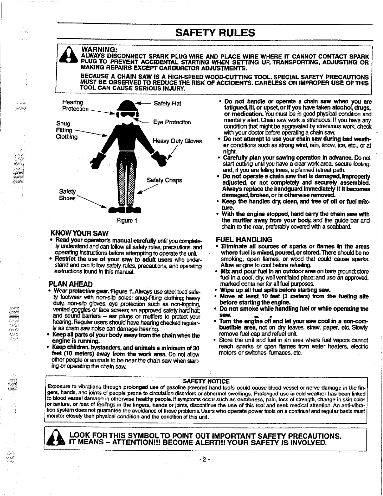
Hearing
Protection_ _1_= "=_----
Safety
Hat
Snug __=.._ Eye Protection
Fitting_---_..._
Clothing
_'="__" Heavy DutyGloves
Safety Chaps
Safety J
Shoes_._
Figure1
KNOW YOUR SAW
• Read your operator'smanual carefullyuntilyoucomplete-
ly understandandcanfollowallsafelyrules,precautions,and
operating_str_-'tions beforeattemptingtooperatetheunit.
• Restrict the use of your saw to adult users whounder-
standandcanfollowsafety rules,precautions,andoperating
instructionsfound inthis manual.
PLAN AHEAD
• Wear protectivegear Figure I Alwaysusesteel-toedsafe-
ty footwearwithnon-slipsoles;snug-f_1_clothing;heavy
duty,non-slipglo_s; eye protectionsuch as non-fogging,
venteegogg=esor racescreen:an approvedsafetyhardhat;
and soundbarriers- ear plugsor mufflers to protectyour
hearingRegularusersshouldhaveheating_ regular
lyas chainsawnoisecandamage hearing
° Keepail partsofyour bodyaway from thechainwhenthe
engine is running
• Keep children,bystanders,and animals a minimum of30
feet (10 meters) away from the work area Do notallow
olheroeopleoranimals to be nearthecha_ sawwhenstart-
ingoroperatingthe chainsaw.
• Do not handle or operate s chain saw when you are
fatigued, ilt, or upset,or ifyou havetaken alcohol,drugs,
or medication. Youmustbe ingoodphysicalconditionand
mentallyalert.Chainsawworkisstrenuous.If youhaveany
conditionthatm_ht be aggravatedbystrenuouswork,check
withyourdoctorbeforeoperatingachainsaw.
• Do not attempt to useyour chainsawduring bad weath-
er condi_onssuchasstrongwind,rain,snow,ice,etc.,orat
night
• Carefully plan your sawing operationin advance. Do not
startcuttinguntilyouhavea clearworkarea, securefooting,
and, ffyouare fellingtrees,a plannedretreatpath.
• Do not operete a chain sew thatis damaged,irnpropedy
adjusted, or not completely and securely assembled.
Always replace the handguardImmediatelyff it becomes
damaged, broken,or is otherwiseremoved
• Keep the handles dr_ clean,and free of oil or fuel mix-
ture.
• W'd_tthe engine stopped,hand carrythe chain saw with
the muffler away from your body,andt_ guidebar and
chainto the rear,preferablycoveredwitha scabbard.
FUEL HANDLING
• Eliminate all sources of sparks or flames in the areas
where fuel ismixed,poured,or storedThare shouldbeno
smoking,open flames,or woodthat could cause sparks.
Allowenginetocoolbeforerefueling.
• Mix and pour fuel inan outdoorareaon bareground;store
fuel ina cool,dry,,wellventilatedplace;and usean approved,
marked container forallfuel purposes.
• Wipe up all fuel spills before startingsaw.
° Move at least 10 feet (3 meters)from the fueling site
before starting the engine.
• DO not smoke while handling fuel or while operatingthe
saw.
• Turn the engine of_and let your saw cool |na noncom-
bustibte area, not on dry leaves,straw,paper, etc Slowly
remov_fuel cap and refuelunit.
• Storethe unitand fuel in an areawherefuel vaporscannot
reach sparks or open flames from water heaters, electric""
motors or switches,furnaces, etc.
SAFETY NOTICE
Exposure to vibra.tionsthrough prolonged use of gasolinepowered hand tools could cause blood vessel or nerve damage in the fin-
gem, hands, arm Iomts of people prone to Circulationdisordersor abnormal swellings. Prolongeduse in cold weather has been linked
toblood vessel damage in othen_se healthy people. If symptomsoccursuch as numbness, pain, loss ofstrength,change in skin color
ortexture, or loss of feelings in the fingers, hands or joints,discontinuethe use of this too_and seek medical attention.An anti-w'bra-
tionsystem does netguarantee the avoidance o_these problems.Users who operate powertoolson a continualand regular basis must
monitorctoseiytheir physical condition and the conditionof this unit.
_1 LOOK FOR THIS SYMBOLTO POINT OUT IMPORTANT SAFETY PRECAUTIONS
IT MEAN S - ATTENTION!!! BECOME ALERT!!! YOUR SAFETY IS INVOLVED
Page 3
,-. SAFETY RULES
OPERATE YOUR SAW SAFELY
• Do not operate a chain saw with one hand. Serious
injurytothe operator,helpers,bystandersor anycombina-
tionof these persons may resultfromone-handedopera-
tion.A chain saw is intendedfortwo-handeduse.
• Operate the chain saw only in well-ventilated outdoor
areas.
• Do not operate saw from a ladder or in a tree, unless
specificallytrained to do so.
• Position all parts of your body to the left of cut and
away from the chain when the engine is running.
• Cut wood only. Do not useyour saw to pryor shoveaway
limbs,roots, or other objects.
• Make sure the chain will not make contact with any
object while starting the engine, Never try to startthe
sawwhen the guide bar is ina cut or kerr.
• Use extreme caution when cutting small size brush
and saplings. Slender materialcan catchthechain and
bewhipped towardyou or pullyouoffbalance.
• Be alert for springback whencuttinga limbthatis under
tensionso you will not be struckbythe limb or sawwhen
thetensioninthe wood fibers isreleased.
• Do not put pressure on the saw at the end of a cut.
Applyingpressurecan cause you to losecontrolwhenthe
cutis completed.
• Stop.the engine before setting the saw down.
• Keep fuel and oil caps, screws, and fasteners securely
tightened.
MAINTAIN YOUR SAW IN GOOD WORKING
ORDER
• Have all chain saw service performed by your Sears
Service Center withtheexceptionofthe itemslistedinthe
"Customer Responsibilities"section of this manual.For
example,if impropertoolsare used to removeor ho{dthe
flywheelwhen servicingthe clutch, structuraldamageto
theflywheelcanoccurandcause the-flywheel toburst.
• Make certain thechain stops moving when the throttle
trigger is released, For correction,refer to 'Carburetor
Adjustments."
• Stop the saw if the chain strikes a foreign object.
Inspectunitand repair or replace parts as necessary.
• Disconnect the spark plug before performing any
maintenance exceptfor carburetor adjustments.
• Never modify your saw in any way. Use onlySEARS '
accessories and replacementpartsas recommended.
TRANSPORTING AND STORAGE
• Stopthe unit before transporting.
• Allow engine to cool, cover the guide bar and chain,and
secure the unitbefore storing or transportingina vehicle.
• Emptyfuel tank before storing or transporting the unit.Use
upany fuel left in thecarburetor by starting the engineand
letting theengine run until itstops.
• Store unitand fuel in an area where fue! vaporscannot
reach sparks or open flames from water heaters, electric
motors or switches, furnaces, etc.
• Store unit so the chain cannot accidentally cause injury.
• Store the unit out of the r_ach of children.
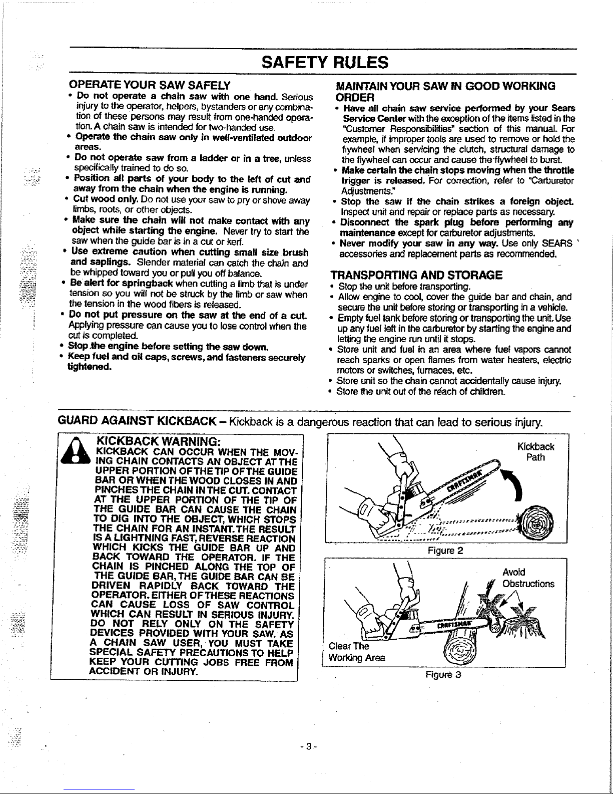
GUARD AGAINST KICKBACK - Kickback is a dangerous reaction that can lead to serious injury.
KICKBACK WARNING:
KICKBACK CAN OCCUR WHEN THE MOV-
ING CHAIN CONTACTS AN OBJECT ATTHE
UPPER PORTION OFTHETIP OFTHE GUIDE
BAR OR WHEN THE WOOD CLOSES IN AND
PINCHES THE CHAIN IN THE CUT.CONTACT
AT THE UPPER PORTION OF THE TIP OF
THE GUIDE BAR CAN CAUSE THE CHAIN
TO DIG INTO THE OBJECT, WHICH STOPS
THE CHAIN FOR AN INSTANT.THE RESULT
IS A LIGHTNING FAST,REVERSE REACTION
WHICH KICKS THE GUIDE BAR UP AND
BACK TOWARD THE OPERATOR. IF THE
CHAIN IS PINCHED ALONG THE TOP OF
THE GUIDE BAR, THE GUIDE BAR CAN BE
DRIVEN RAPIDLY BACK TOWARD THE
OPERATOR. EITHER OFTHESE REACTIONS
CAN CAUSE LOSS OF SAW CONTROL
WHICH CAN RESULT IN SERIOUS INJURY.
DO NOT RELY ONLY ON THE SAFETY
DEVICES PROVIDED WITH YOUR SAW. AS
A CHAIN SAW USER, YOU MUST TAKE
SPECIAL SAFETY PRECAUTIONS TO HELP
KEEP YOUR CUTTING JOBS FREE FROM
ACCIDENT OR INJURY.
ClearThe
WorkingArea
Figure2
Figure 3
Kickback
Path
Avoid
Obstructions
-3 ¸-
Page 4
k
SAFETY RULES
"'2";
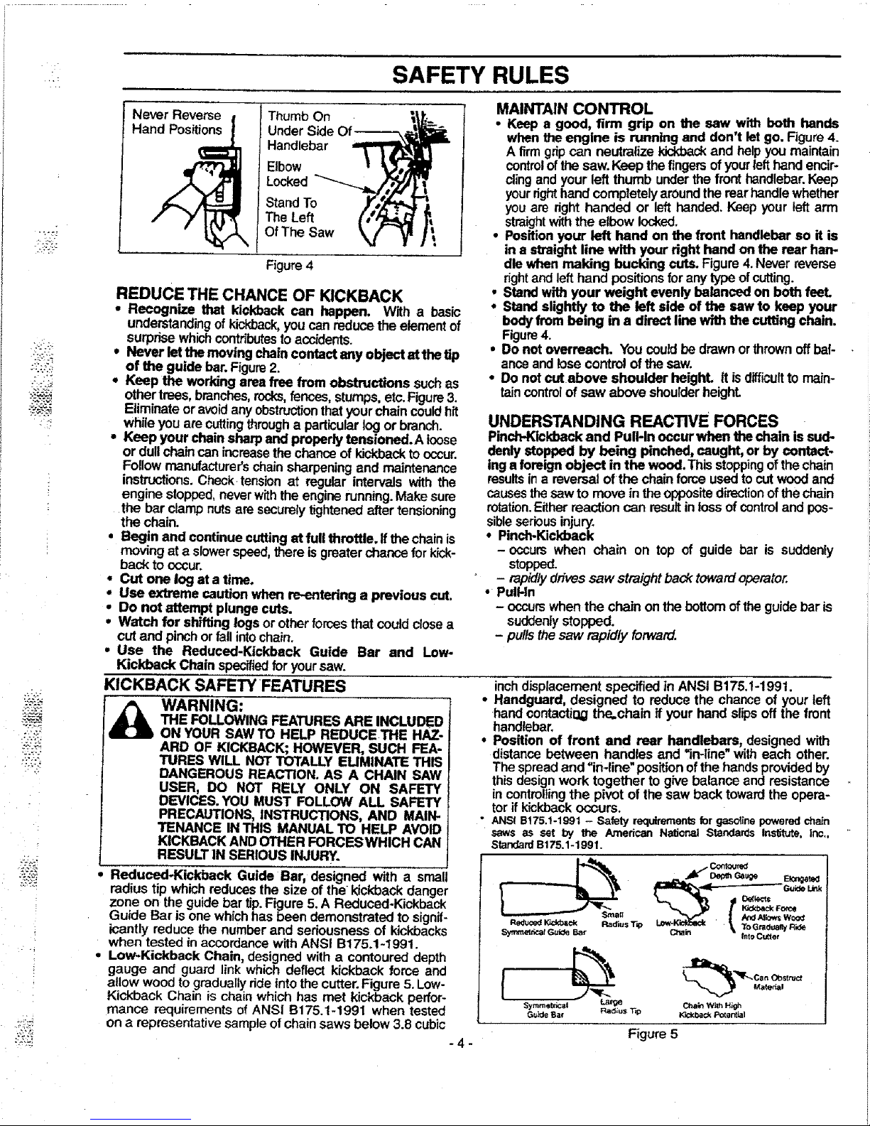
Ha ! Under Side Of
_ Handlebar
| Elbow
_Locked "'_
lstand
t OfThe Saw
Figure4
REDUCE THE CHANCE OF KICKBACK
• Recognize that kickback can happen. With a basic
understandingof kicl_ack,you canreduce the elementof
surprisewhichcontributesto accidents.
* Never letthe moving chaincontact any object at the tip
of the guide bar. Figure2.
. Keep the working area free from obstructions suchas
othertrees, branches,rocks,fences,stumps,etc.Figure3.
Eliminateor avoidanyobstructionthat your chaincouldhit
while you arecuttingthrougha particularlogor branch.
, Keep your chain sharp and properly tenaioned.A loose
or dullchaincan increasethe chanceofkickbackto occur.
Followmanufacturer'schainsharpeningand maintenance
instructions.Check tensionat regular intervals with the
engine stopped,neverwiththe engine running.Makesure
the bar clamp nutsare securelytightenedafter tensioning
the chain.
• Begin and continuecutting at full throttle. If thechain is
moving at a slowerspeed,there isgreaterchance forkick-
back to occur.
• Cut one log at a time.
• Use extreme caution when re-entering a previous cut.
• Do not attempt plunge cuts.
• Watch for shifting logsor other forcesthat couldclosea
cutand pinchorfall intochain.
° Use the Reduced-Kickback Guide Bar and Low-
Kickback Chain specked foryoursaw.
KICKBACK SAFETY FEATURES
_ WARNING:
THE FOLLOWINGFEATURES ARE INCLUDED
ON YOUR SAW TO HELP REDUCE THE HAZ-
ARD OF KICKBACK; HOWEVER, SUCH FEA-
TURES WILL NOT TOTALLY ELIMINATE THIS
DANGEROUS REACTION. AS A CHAIN SAW
USER, DO NOT RELY ONLY ON SAFETY
DEVICES. YOU MUST FOLLOW ALL SAFETY
PRECAUTIONS, INSTRUCTIONS, AND MAIN-
TENANCE IN THIS MANUAL TO HELP AVOID
KICKBACK ANDOTHER FORCESWHICH CAN
RESULT IN SERIOUS INJURY.
Reduced-Kickback Guide Bar, designed with a sma
radius tip,whichreduces the size of the kickback danger
zone on me guioe par tip. Figure 5,A Reduced-Kickback
Guide Bar is one whichhas been demonstrated to signif-
icantly reduce the number and seriousness of kickbacks
MAINTAIN CONTROL
• Keep a good, firm grip on the saw with both hands
when the engine is running and don't let go. Figure4.
A firm grip can neutralize kickbackand help you maintain
controlof the saw. Keep the fingersof your left hand encir-
cling and your left thumb under the front handlebar.Keep
your righthand completely around the rear handle whether
you are right handed or left handed. Keep your left arm
straightwiththe elbow locked,
• Position your left hand on the front handlebar so it is
in a sl_aightline with your right hand onthe rear harp
die when making bucking cuts. Figure4.Never reverse
right andlefthand positionsforany type ofcutting.
• Stand with your weight evenly balanced on both feel
• Stand slightly to the left side of the saw to keep your
bodyfrom being in a direct line with the cutting chain.
Figure4.
• Do not overreach. Youcouldbe drawnor thrownoffbal-
anceand losecontrol of the saw.
• Do not cut above shoulder heighL It isdifficult to main-
taincontrol of saw above shoulderheight.
UNDERSTANDING REACTWE FORCES
Pinch-Kickback and Puff-Inoccur when thechain issud-
denly stopped by being pinched, caught, or by contact-
inga foreignobject in the wood.This stoppingof the chain
resultsina reversal of the chain forceusedtocut wood and
causesthesawto movein the oppositedirectionofthechain
rotation.Eitherreactioncan resultinlossofcontrol and pos-
sibleseriousinjury.
• Pinch-Kickback
-occurs when chain on top of guide bar is suddenly
stopped.
- rapidlyd/_vessaw straightbacktowardoperator.
• PulHn
- occurswhen the chain on the bottomofthe guidebar is
suddenlystopped.
- pulisthesaw rapidly forward.
inchdisplacement specified in ANSI B175.1-1991.
Handguard, designed to reducethe chance of yourleft
handcontactiQgthe.chain if your hand slipsoff the front
handlebar,
Position of front and rear handlebars, designed with
distancebetween handles and =in-line"witheach other.
The spreadand =in-line" positionofthe handsprovidedby
thisdesignwork together to give balance and resistance
in centmlling the pivot of the saw back toward the opera-
tor ifkickbackoccurs.
ANS! B175.1-1991 - Safety requirements for gasotine powered chain
saws as set by the ._nedcan NaSor_l Standards Institute, inc.,
Standard B175.1-1991.
2 ._ Dep_ Gauge Ek:ng_
ReducedlGdd_ck Rad{usT_) Lo_-KL_Ee_ _ To Gra_lualty Ride
_nf_tettP..af G_i_} Bar Chain l_to C_ter
when tested in accordance with ANSI B175.t-1991.
Low-Kickback Chain, designed with a contoured depth
gauge and guard link which deflect kickback force and
allow woodto gradually ride into the cutter. Figure 5. Low-
Kickback Chain is chain which has met kickback perfor-
mance requirements of ANSI B175.1-1991 when tested
on a representative sampleof chain saws below 3.8 cubic
-4-
{
Sym_etricat Large
Guide Bat Rad;u$ T'=p
Male_l
C_ain With H_gh
Kick_¢_ Poter_ia_
Figure 5
Page 5
7:.
i
"kY_
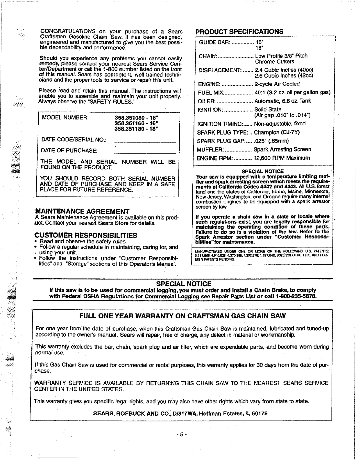
CONGRATULATIONS on your purchase of a Sears
Craftsman Gasoline Chain Saw. It has been designed,
engineered and manufactured to give you the best possi-
ble dependability and performance.
Should you experience any problems you cannot easily
remedy, please contactyour nearest Sears Service Cen-
ter/Department orcallthe 1-800 number listedon the front
of this manual. Sears has competent, welltrained techni-
cians and the propertoolsto service or repair this unit.
Please read and retain this manual. The instructions wilt
enable you to assemble and maintain your unit properly.
Always observe the =SAFETY RULES."
MODEL NUMBER:
358.351080-18"
358.351160-16"
358.351180-18"
DATE CODE/SERIAL NO.:
DATE OF PURCHASE:
THE MODEL AND SERIAL
FOUND ON THE PRODUCT.
NUMBER WILL BE
YOU SHOULD RECORD BOTH SERIAL NUMBER
AND DATE OF PURCHASE AND KEEP IN A SAFE
PLACE FOR FUTURE REFERENCE.
J
MAINTENANCE AGREEMENT
A Sears Maintenance Agreement is available on this prod-
uct. Contact your nearestSears Store for details.
:CUSTOMER RESPONSIBILITIES
• Read and observe thesafety rules.
• Followa regularschedule in maintaining, caring for, and
, using your unit.
• Follow the instructions under "Customer Responsibi-
lities" and "Storage" sectionsof this Operator's Manual
PRODUCT SPECIRCATIONS
GUIDE BAR: ............... 16"
18"
CHAIN: ........................ Low Profile 3/8" Pitch
Chrome Cutters
DISPLACEMENT: ....... 2.4 Cubic inches (40cc)
2.6 Cubic Inches (42cc)
ENGINE: ..................... 2-cycte Air Cooled
FUEL MIX:................... 40:1 (3.2 oz.oil per gallon gas)
OILER: ........................ Automatic, 6.8 oz.Tank
IGNITION: ................... Solid State
(Air gap .010" to .014")
IGNITION TIMING: ...... Non-adjustable, fixed
SPARK PLUG TYPE: .. Champion (CJ-7Y)
SPARK PLUG GAP:......025" (.65ram)
MUFFLER: .................. Spark Arresting Screen
ENGINE RPM: ............ 12,600 RPM Maximum
SPECIAL NOTICE
Your saw is equipped with e temperature limiting muf-
tier and spark arresting screen which meets the require-
ments of Celifomla Codes 4442 and 4443. All U.S. forest
land and _e states of California, Idaho, Maine, Minnesota,
New Jersey, Washington, and Oregon require many internal
combustion engines to be equipped with a spark arrestor
screen by law.
If you operate a chain saw in a state or locale where
such regulations exist, you ere I..e_lellyresponsible lor
malntalning the operating condition of these pa.rts.
Failure to do so is a violation of the law. Refer to trio
Spark Arrestor section under "Customer Responsi-
bilities" for maintenance.
MANUFi_'_TUREO UNDER ONE OR MORE OF THE FOLLOWING U,S. PATENTS:
5,367,_J_; 4.940,028; 4,370,85S; 4,302.87_; 4,197,64_, D325_330, OTHER U,S. AND FOR-
EIGN PATENTS PENDING,
' sPECIAL NOTICE
Ifthis saw is to be used for commercial logging, you must order and install a Chain Brake, to comply
with Federal OSHA Regulations for Commercial Logging see Repair PaL_sList or call 1-800-235-5878.
FULL ONE YEAR WARRANTY ON CRAFTSMAN GAS CHAIN SAW
\
For one year fromthe date of purchase, when this Craftsman Gas Chain Saw is maintained, lubricated and tuned-up
accordingto the owner's manual Sears will repair, free of charge, any defect in matedal or workmanship.
This warranty excludesthe bar, chain, 'spark plug and air filter, whichare expendable parts, and become worn during
normal use.
Ifthis Gas Chain Saw is used for commercial or rental purposes,this warrantyapplies for 30 days fromthe date of pur-
chase.
WARRANTY SERVICE IS AVAILABLE BY RETURNING THIS CHAIN SAW TO THE NEAREST SEARS SERVICE
CENTER IN THE UNITED STATES.
This warranty givesyou specific legal rights, and you may also have other rights whichvary from state to state.
SEARS, ROEBUCK AND CO.,DI817WA, Hoffman Estates, IL 60179
-5-
Page 6
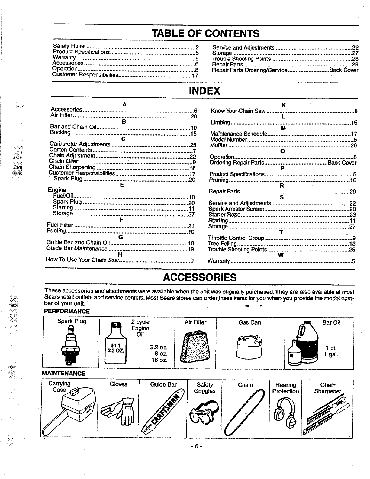
TABLE OF CONTENTS
".?_: J
___
Safety Rules...................................................................... 2
Product Specifications .........................._............................ 5
Warranty ............................................................................ 5
Accessories ....................................................................... 6
Operation .......................................................................... 8
Customer Responsibilities ............................................... :17
Service and Adjustments................................................ 22
Storage............................................................................ 27
Trouble Shooting Points.................................................. 28
Repair Parts .................................................................... 29
Repair Parts Ordering/Service .......................... Back Cover
INDEX
A
Accessories ....................................................................... 6
Air Filter........................................................................... 20
B
Bar and Chain Oil ............................................................ 10
Bucking............................................................................ 15
C
Carburetor Adjustments .................................................. 25
Carton Contents ................................................................ 7
Chain Adjustment.................................................. ,.........22
Chain Oiler ............................... _........................................ 9
Chain Sharpening ........................................................... 18
Customer Responsibilities ............................................... 17
Spark Plug ................................................. L................20
E
Engine
Fuel/Oil ......................................................................... 10
Spark Plug ................................................................. 20
Starting......................................................................... 11
Storage ........................................................................ 27
F
Fuel Filter........................................................................ 21
Fueling ............................................................................. t0
G
Guide Bar and Chain Oi!................................................. 10
Guide Bar Maintenance .................................................. 19
H
How To Use Your Chain Saw............................................. 9
K
Know YourChain Saw ................................... .....................8
L
Limbing............................................................................ 16
M
Maintenance Schedule.................................................... 17
Model Number................................................................... 5
Muffler ............................................................................. 20
O
Operation............................................................. ..............8
Ordedng Repair Parts....................................... BackCover
P
ProductSpecifications....................................................... 5
Pruning..................................................... :...................... 16
R
Repair Parts ................................. _................................... 29
S
Service and Adjustments .................................... i...........22
Spark Arrestor Screen..................................................... 20
Starter Rope.................................................................... 23
Starting ............................................................................ 11
Storage.......................................................... _................. 27
T
ThrotUeControl Group .................................................. _...g
Tree Felling...................................................................... 13
Trouble ShootingPoints.................................................. 28
W
Warranty............................................................................ 5
ACCESSORIES
These accessoriesand attachmentswere availablewhen the unit was originallypurchased.They are also availableat most
Sears retail outletsand servicecenters. Most Sears storescan orderthese itemsforyouwhen you provide the model num-
ber of your unit. ._ .
Air Filter Bar Oil
PERFORMANCE
Spark Plug
MAINTENANCE
Carrying
_ -cycle
Engine
Oil
3.2 oz.
8 oz.
t6 oz.
Gas Can
1 gat,
Gloves
J
Guide Bar
Safety Chain
Goggles
Hearing
Protection
Chain
f
Page 7
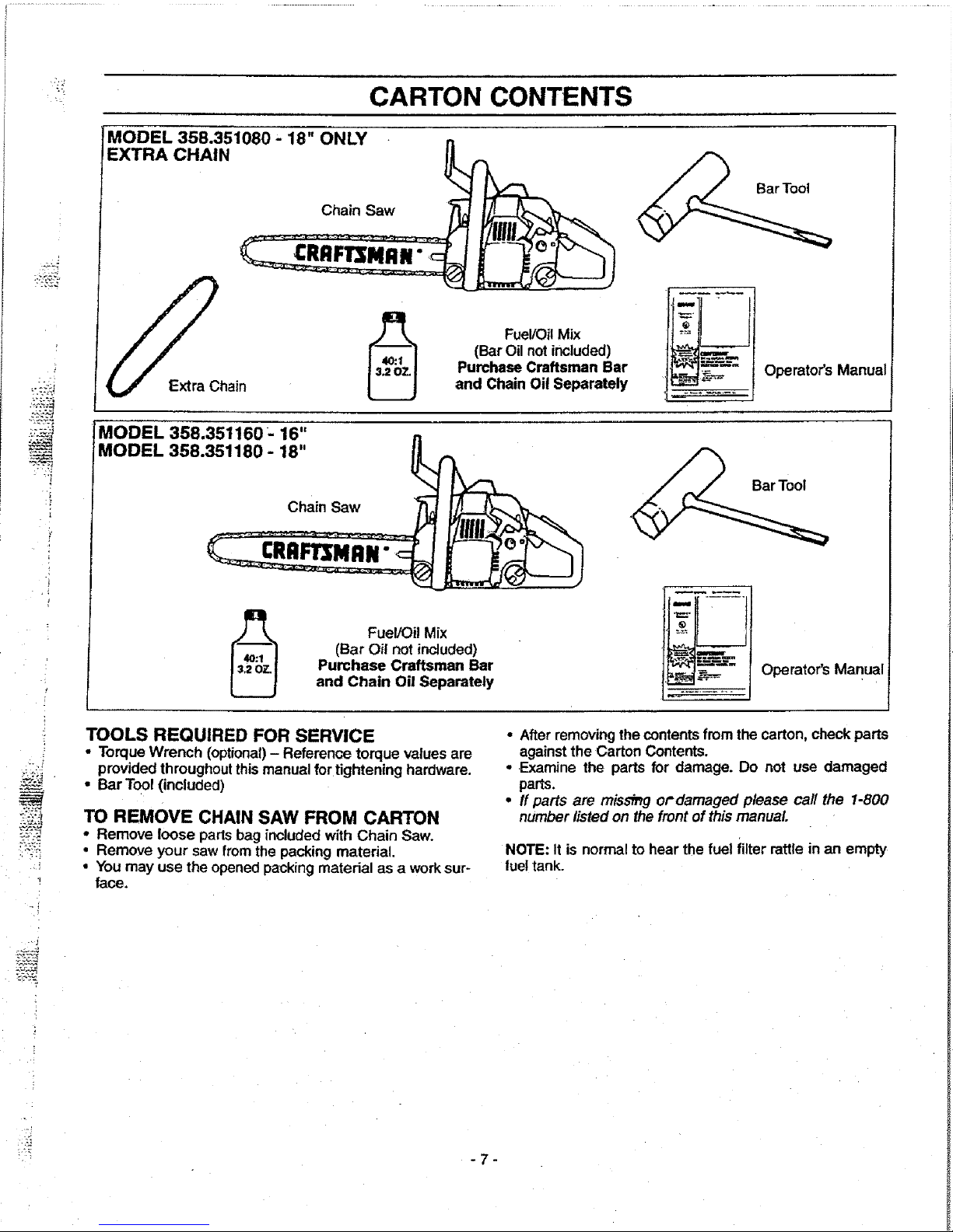
CARTON CONTENTS
?
i
.!
MODEL 358.351080.18" ONLY • n
EXTRA CHAIN _
Extra Chain
Fuel/OilMix
(Bar Oil not included)
Purchase Craftsman Bar
and Chain Oil Separately
Operator's Manual
MODEL 358.351160- 16"
MODEL 358.351180 - 18" _:_
Cha,n Saw j__
FueVOi!Mix
(Bar Oil not included)
Purchase Craftsman Bar
and Chain Oil Separately
Operator's Manual
TOOLS REQUIRED FOR SERVICE
• Torque Wrench (optional)- Reference torque values are
providedthroughoutthismanualfor tightening hardware.
• Bar Tool (included)
TO REMOVE CHAIN SAW FROM CARTON
• Remove loose paris bag included with Chain Saw.
• Remove your saw from the packing material.
• You may use the opened packing material as a work sur-
face.
• Afterremovingthe contentsfrom the carton, check parts
againstthe Carton Contents.
• .Examine the parts for damage. Do not use damaged
parts.
• tf parts are miss_g or'damaged please call the 1-800
number listedon the frontof thismanual
NOTE: It is normal to hear the fuel filter rattle in an empty
lue!tank.
-7-
Page 8
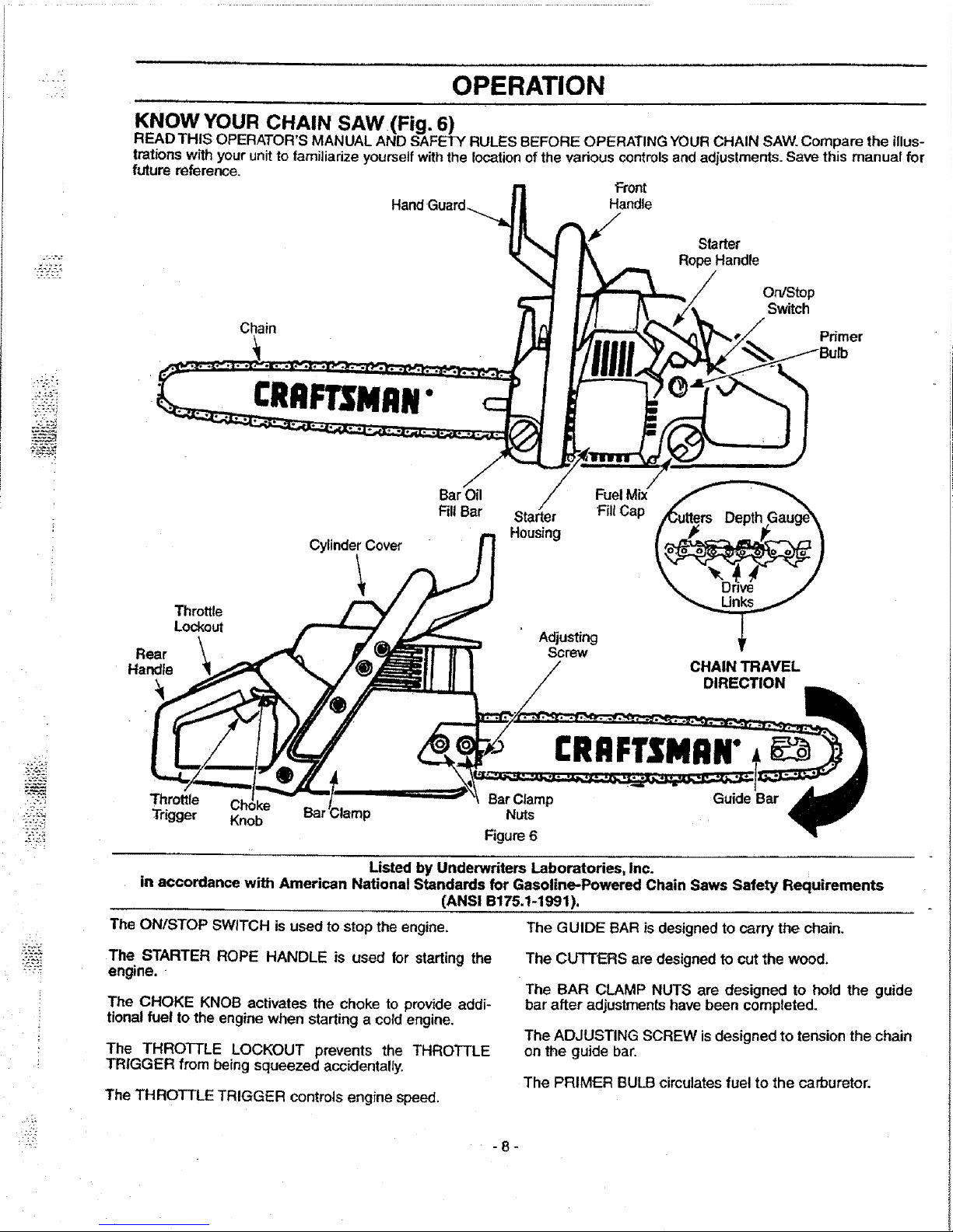
* OPERATION
KNOW YOUR CHAIN SAW(Fig. 6)
READ THIS OPERATOR'S MANUAL AND SAFETY RULES BEFORE OPERATING YOUR CHAIN SAW.Compare the illus-
trations with your unitto familiarizeyourselfwiththe locationofthe various controlsand adjustments. Save this manual for
future reference.
Front
Hand_( Handle
Chain
Starter
RopeHandle
On/Stop
Switch
Primer
CRRFTSNRN"
Throttle
Lockout
CylinderCover
BarOil
FillBar Starter Fill Cap
Housing
Adjusting
Screw
Rear
Handle CHAIN TRAVEL
DIRECTION
CRRFTSMRN"
Guide Bar
Throttle BarClamp
Trigger Knob Bar_ Nuts
Figure6
Listed by Underwriters Laboratories, Inc.
in accordance with American National Standards for Gasoline-Powered Chain Saws Safety Requirements
(ANSI B175.1-1991 ).
The ONISTOP SWITCH is used to stop the engine.
The STARTER ROPE HANDLE is used for starting the
engine. •
The CHOKE KNOB activates the choke to provide addi-
tional fuel to the engine when starting a coldengine.
The THROTTLE LOCKOUT prevents the THROTTLE
TRIGGER from being squeezed accidentally.
The THROTTLE TRIGGER controls engine speed.
The GUIDE BAR is designed to carry the chain.
The CUTTERS are designedto cut the wood,
The BAR CLAMP NUTS are designed to hold the guide
bar after adjustments have been completed.
The ADJUSTING SCREW is designed to tension the chain
on the guide bar.
The PRIMER BULB circulates fuel to the carburetor.
" -8-
Page 9
• :,k!
.r . _"
r ,
OPERATION
HOWTO USE YOUR CHAIN SAW
STOPPING YOUR ENGINE
' Move on/stop switch to the "Stop"position.
, If engine does not stop, pullb_uechokeknobout fully.
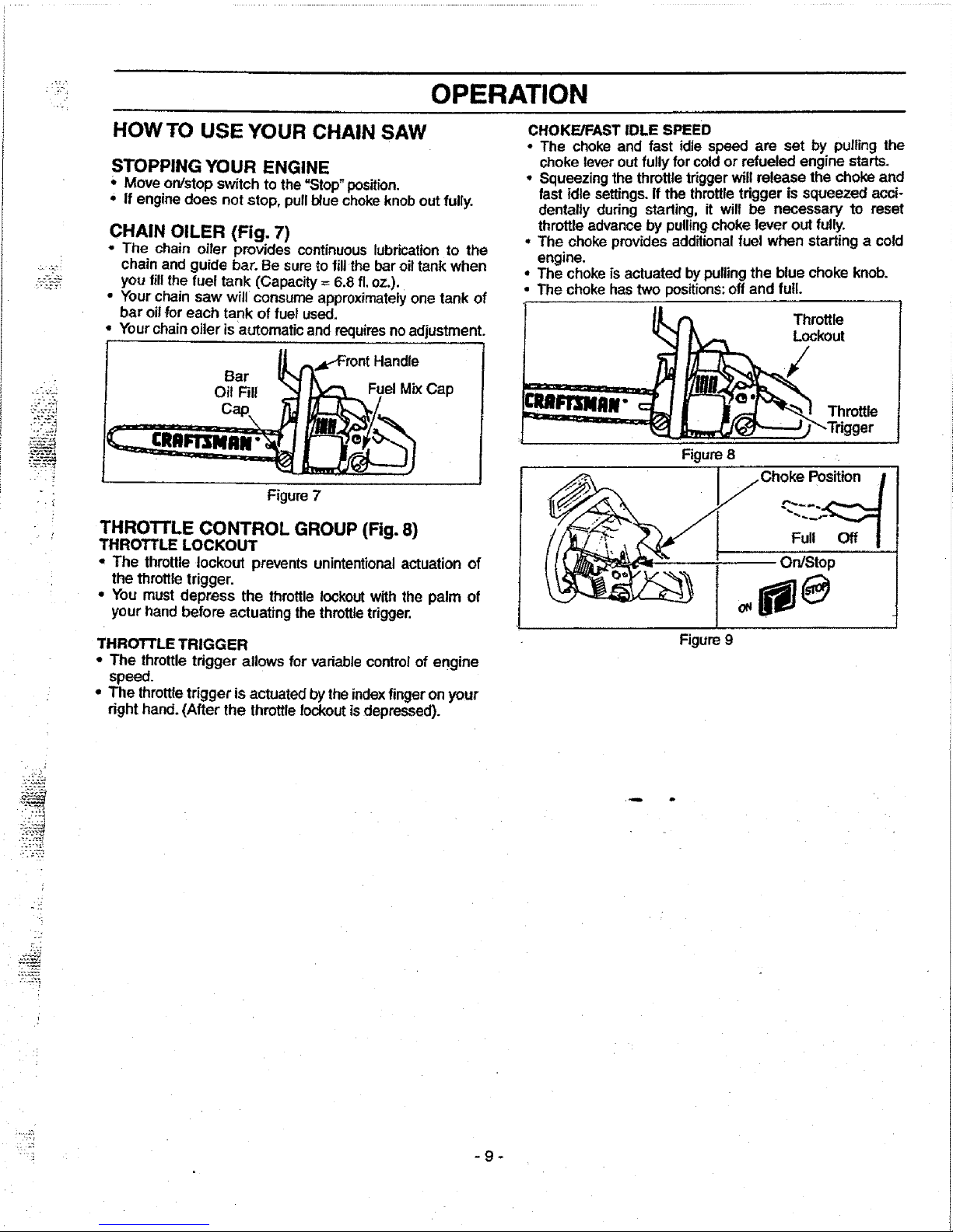
CHAIN OILER (Fig. 7)
• The chain oiler provides continuouslubricationto the
chainand guide bar.Be sureto figthe bar oiltank when
you fillthe fuel tank (Capacity= 6.8 fl,oz.).
• Your chain saw will consume approximatelyone tank of
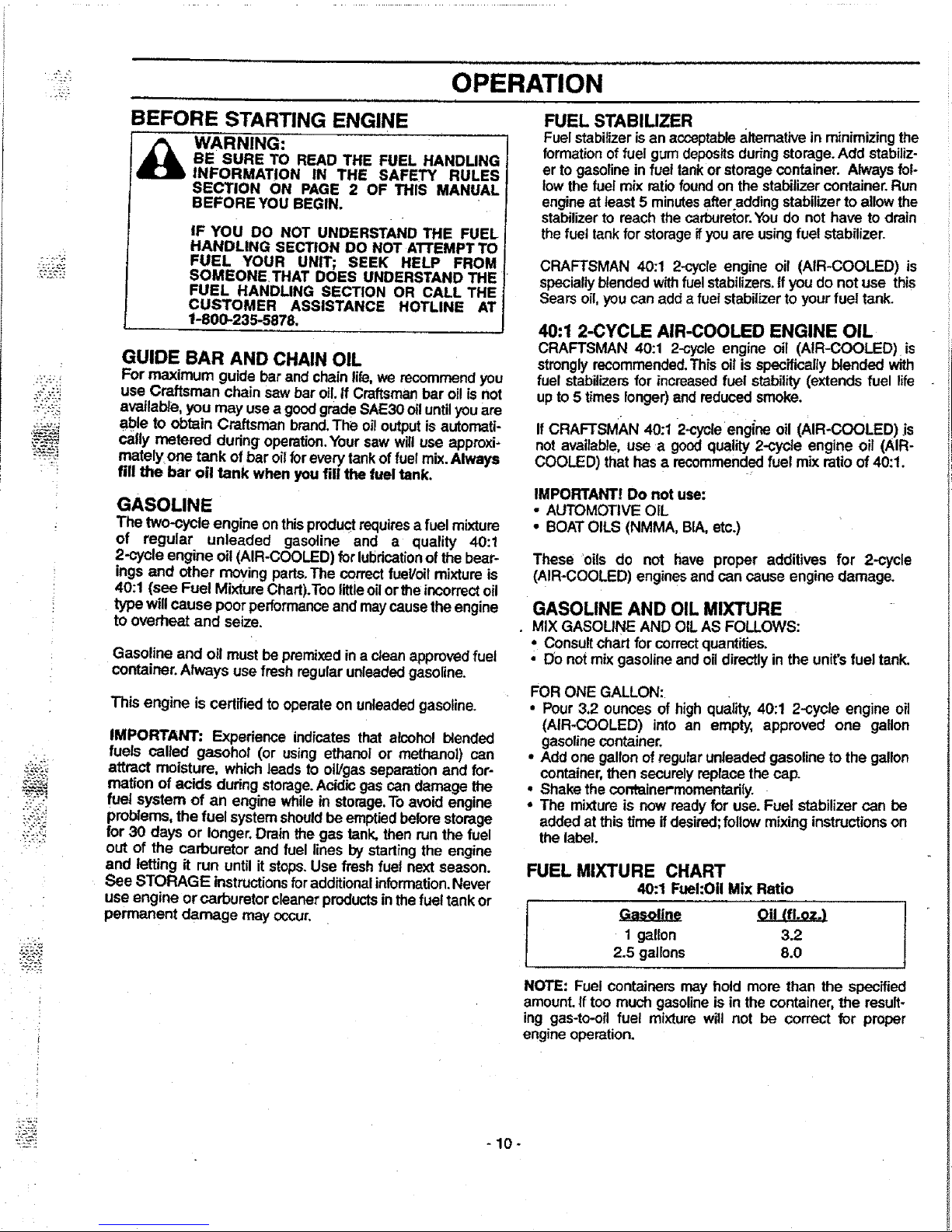
CHOKE/FAST IDLE SPEED
• The choke and fast idle speed are set by pulling the
chokelever outfullyfor cold or refueled engine starts.
• Squeezing the throttletriggerwill release the chokeand
fast idle settings.If the throttletrigger is squeezed acci-
dentally during starling, it will be necessary to reset
throttleadvance by pullingchoke lever out fully.
• The choke providesadditionalfuel when starting a cold
engine.
• The chokeis actuated by pullingthe blue choke knob,
• The chokehastwo positions:off and full.
bar oil for each tank of fuel used.
• Your chainoiler isautomatic and requiresnoadjustment.
Handle
Bar
Oil Fill Fuel MixCap
Figure7
THRO'n'LE CONTROL GROUP (Fig. 8)
THROTTLE LOCKOUT
• The throttle lockout prevents unintentionalactuation of
the throttletrigger.
° You must depress the throttlelockoutwith the palm of
your handbefore actuating the throttletrigger.
THROTTLE TRIGGER
• The throttle trigger allows for vadablecontrolof engine
speed.
• The throttle trigger is actuated bythe indexfingeron your
dght hand. (After the throttlelockoutisdepressed).
Throttle
Lockout
Throttle
Figure8
Figure9
".:::?
Page 10
OPERATION
.JP
£:=?_
BEFORE STARTING ENGINE
WARNING:
BE SURE TO READ THE FUEL HANDLING
INFORMATION IN THE SAFETY RULES
SECTION ON PAGE 2 OF THIS MANUAL
BEFORE YOU BEGIN.
IF YOU DO NOT UNDERSTAND THE FUEL
HANDLING SECTION DO NOT ATTEMPT TO
FUEL YOUR UNIT; SEEK HELP FROM
SOMEONETHAT DOES UNDERSTAND THE
FUEL HANDLING SECTION OR CALL THE
CUSTOMER ASSISTANCE HOTLINE AT
1-800-235-5878,
GUIDE BAR AND CHAIN OIL
For maximum guide bar and chainlife,we recommendyou
use Craftsman chain saw bar oil.if Craftsmanbar oilis not
available,you may use a goodgrade SAE30 oiluntilyou are
able to obtain Craftsman brand,The oi! outputis automati-
cally metered during operation.Your saw willuse approxi-
mately one tank of bar oilforeverytankof fuelmix.Always
fill the bar oil tank when you fill the fuel tank.
GASOLINE
The two-cycle engine on thisproductrequiresa fuel mixture
of regular unleeded gasoline and a quality 40:1
2-cycle engine oi!(AIR-COOLED) forlubricationofthe bear-
ings and other movingparts.The correctfuel/oilmixture is
40:1 (see Fuel MixtureChart).Too littleoilorthe incorrectoil
typewill cause poor performanceand maycausethe engine
to overheat and seize.
Gasoline and oll mustbe premixedina clean approvedfuel
container.Always usefresh regularunleadedgasoline.
This engine is certifiedto operateon unleadedgasoline.
IMPORTANT: Experience indicates that alcohol blended
fuels called gasohol (or using ethanol or methanol) can
attract moisture, which leads to oil/gasseparationand for-
marion of acids duringstorage.Acidicgas can damage the
fuel system of an engine whilein storage.Toavoid engine
problems, the fuel systemshouldbe emptiedbefore storage
for 30 days or longer,Drainthe gas tank, then run the fuel
out of the carburetor and fuel lines bystarting the engine
and letting it run untilit stops. Use fresh fuel nextseason.
See STORAGE instructionsforadditionalinformation.Never
use engine or carburetor cleaner productsinthefuel tank or
permanent damage may occur.
FUEL STABILIZER
Fuel stabilizerisan acceptablea.ltemativeinminimizingthe
formation offuel gum depositsduringstorage.Add stabiliz-
er togasoline infuel tank orstoragecontainer. Alwaysfol-
towthe fuel mix ratiofound on the stabilizercontainer. Run
engineat teast5 minutesafteraddingstabilizerto allow the
stabilizerto reach the carburetor.Youdo not have to drain
thefuel tankfor storageifyou are usingfuel stabilizer.
CRAFTSMAN 40:1 2-cycle engine oil (AIR-COOLED) is
specially blended w_ fuel stabilizers.If you do not use this
Searsoil,you can add a fuelstabilizer to your fuel tank.
40:1 2-CYCLE AIR-COOLED ENGINE OIL
CRAFTSMAN 40:1 2-cycle engine oil (AIR-COOLED)is
stronglyrecommended.This oil is specificallyblended with
fuel stabilizersfor increased fuel stability(extends fuel I_fe
upto 5 times longer)and reducedsmoke.
If CRAFTSMAN 40:1 2-cycleengi_neoil (AIR-COOLED).is
not avellabie, use a good quality 2-cycle engine oil (AIR-
COOLED) that has a recommended fuel mix ratio of 40:1.
IMPORTANT! Do not use:
• AUTOMOTIVE OIL
• BOAT OILS (NMMA, BIA,etc.)
These oils do not have proper additives for 2-cycle
(AIR-COOLED) enginesandcan cause engine damage.
GASOLINE AND OIL MIXTURE
• MIX GASOLINE AND OIL AS FOLLOWS:
• Consultchart for correctquantities.
• Do not mix gasolineandoil directlyin the unit'sfuel tank,
FOR ONE GALLON:
• Pour 3,2 ounces of high quality,40:1 2-cycle engine oil
(AIR-COOLED) into an empty, approved one gallon
gasolinecontainer.
• Add one gallonof regular unleadedgasoline to the gallon
container,then securelyreplacethe cap.
• Shake the corttainet'momentadly.
• The mixture is nowready for use. Fuel stabilizer can be
addedat this time ifdesired;follow mixinginstructionson
thelabel+
FUEL MIXTURE CHART
40:1 Fuel:Oil Mix Ratio
I _ Oil (fLoz.I
1 gallon 3.22.5 gallons 8.0
NOTE: Fuel containers may hold more than the specified
amount.Iftoo much gasolineis in the container, the result-
ing gas-to-oil fuel mixture will not be correct for proper
engineoperation.
-10-
Page 11

OPERATION
@
STOPPING YOUR ENGINE
• Move on/stopswitchto the "Stop" position.
• if engine does notstop, pull blue chokeknob outfully.
_ WARNING:
ALWAYS WEAR GLOVES, SAFETY FOOT-
WEAR, SNUG-FITTING CLOTHING, AND
EYE, HEARING, AND HEAD PROTECTION
DEVICES WHEN OPERATING A CHAIN SAW.
THE CHAIN MUST NOT MOVE WHEN THE
ENGINE RUNS AT IDLE SPEED, REFER TO
THE "CARBURETOR ADJUSTMENTS" SEC-
TION FOR CORRECTION.
AVOID ANY CONTACT WITH THE MUFFLER.
A HOT MUFFLER CAN CAUSE SERIOUS
BURNS.
NOTE: Check chain tension using instructions in the
=Service and Adjustment" section.
• Before first use.
• After I minute of operation.
TO START ENGINE (Fig. 10 & 11)
COLD ENGINE START AND WARM ENGINE
START AFTER RUNNING OUT OF FUEL
• Fuel enginewith 40:1 fuel mix (3.2 oz.to 1 gaLgas).
• Fil! bar oil tank with bar oil Your saw will use approxi-
mately one tank of bar oil for each tank of fuel mix.
• Prime engine by pressing primer bulb six times.
• Turn on ignition by moving on/stop switch to the "On"
position.
° Putl the blue choke/fast idle control out fully to set both
the choke and fast idle for starting. Then set the saw on
the ground. Grip the front handle withyour left hand and
place your right foot through the openingin the rear han-
dle.
• IFTHROTTLETRIGGER IS SQUEEZED ACCIDENTAL-
LY DURING STARTING ff WILL BE NECESSARY TO
RESET THE CHOKFJFAST IDLE CONTROL.
NOTE: When pulling the starter rope, do not use the full
extent of the rope as thiscan cause the rope to break. Do
not let the starter rope snap back, holdthe handleand let
the rope rewindslowly.
• Pull starter rope handle with your right hand until the
engine attempts to start.Then pushthe blue choke knob
in to the partial position.Resume pulling handle until
engine starts.
• Above 40 degrees, allowengine to runtot approximate-
ly 5 seconds, push the choke knob in to the =Off" posi-
tion, then squeeze and release throttletrigger to allow
engine to idle.
• Below 40 degrees, allowengine towarm up 30 seconds
- 1 minute with choke at partial position.Push choke
knob in to the "Off" position,then squeeze and release
throttle triggerto allow engine to idle.
• To stop engine, move on/stop switchto the =Stop" posi-
tion.
Figure. 10
Position /
Full
On/Stop
@
STARTING A WARM ENGINE
• Move on/stopswitchto the "On_position.
• Engage thechokeJfastidleby pullingout the bluechoke
knobfully and pushingit back infully.
• Be sure choke is in the=Off"position.
• With saw on ground,grip fronthandlewith lefthand and
place yourright footthroughopeningin rear handle.
• Pull starter rope handle untilengine starts.
• Squeeze and release throttletrigger to returnengine to
idle speed.
RightnHand
Starter Rope Handle,
! /__ LeftHand
Right Foot throughOpening in Rear Handle
Figure 11
DIFFICULT sTARTlinG OR FLOODED ENGINE
The engine may be floodedwith too muchfuel if it has not
started after 10 pulls.
Floodedengines can be cleared of excessfuel withthe fol-
lowingprocedure:
• Pull out the blue choke/fast idle control fully and then
pushit back into the=Off"positionto setthefast idlecon-
trotto the start position.
° Verifythat the on/stop switch isin the "On" position.
• Push the choke knob to the =Off" position.
• With saw on ground, grip fronthandle with lefthand and
place right footthrough opening in rear handle.
• Pull starter rope handle untilengine starts.
Starting could require pulling starter rope handle many
times depending on how badly unit is flooded. If enginestill
fails to start, refer to "TROUBLE SHOOTING" chart orcal!
the 1-800 number listedon the front page of thismanual.
-11-
Page 12

•7:i
.... =
OPERATION
,.,,, ,,............ ii
GENERAL OPERATION TIPS
• cut woodonly.Do not cutmetal;plastics;masonry;non-
woodbuilding materials;etc.
• Stopthe saw ifthe chain strikesa foreignobject.Inspect
the saw and repair or replace parts as necessary.
• Keepthe chain outof dirtand sand. Evena sma!lamount
of dirt will quicklydull a chain and thusincreasethe pos-
sibilityof kickback.
To getthe =feel"of usingyoursaw beforeyoubegina major
sawing operation, practice cutting a few small Jogsusing
the following technique:
• Accelerate engine tofullthrottleby squeezingthethrottle
triggerbefore enteringcut.
• Never cutwith engine at partialspeeds.
• Begincuttingwith the saw chassisagainst the log.
• Keep engine at full throttleduringcuttingprocedure.
• Allow the chainto cut for you;exert only lightdownward
pressure.If you force the cut,damage to the bar, chain,
or enginecan result.
• Release the throttletrigger as soon as the cut is com-
pleted, allowingthe engine to idle.If you run the unit at
full throttlewithoutcutting,unnecessarywear can occur
tothe chain, bar, and engine.
• To avoid losingcontrolwhencompleting the cut, do not
put pressureon the sawduringthe endof the cut.
• Stop engine beforesettingunitdownafter operation.
OPERATION SAFETY
,,i,,.Hi m Hi L i,H Hi =
WARNING:
IF SAW BECOMES PINCHED OR HUNG IN A
LOG, DO Nor TRY TO FORCE IT OUT.YOU
CAN LOSE CONTROL OF THE SAW
RESULTING IN INJURY AND/OR DAMAGE
TO THE SAW. STOP THE SAW, DRIVE A
WEDGE OF PLASTIC OR WOOD INTO THE
CUT UNTIL THE SAW CAN BE REMOVED
EASILY. RESTARTTHE SAW AND CAREFUL-
LY REENTER THE CUT. TO AVOID KICK-
BACK AND CHAIN DAMAGE, DO NOTUSE A
METAL WEDGE. DO NOT ATTEMPT TO
RESTART YOUR SAW WHEN IT IS PINCHED
OR HUNG IN A LOG.
KICKBACK CAN OCCUR WHEN THE MOV-
ING CHAIN CONTACTS AN OBJECT ATTHE
UPPER PORTION OFTHETIP OFTHE GUIDE
BAR OR WHEN THE WOOD CLOSES IN AND
PINCHES THE SAW CHAIN IN THE CUT.
CONTACT AT THE UPPER PORTION OF THE
TIP OF THE GUIDE BAR CAN CAUSE THE
CHAINTO DIG INTOTHE OBJECT AND STOP
THE CHAIN FOR AN INSTANT.THE RESULT
IS A LIGHTNING FAST,REVERSE REACTION
WHICH KICKS THE GUIDE BAR UP AND
BACK TOWARD THE OPERATOR, IF THE
SAW CHAIN IS PINCHED ALONG THE TOP
OF THE GUIDE BAR, THE GUIDE BAR CAN
BE DRIVEN RAPIDLY BACK TOWARD THE
OPERATOR. EITHER OFTHESE RE.ACTIONS
CAN CAUSE LOSS OF SAW CONTROL
WHICH CAN RESULT IN SERIOUS INJURY.
AVOID REACTIVE PINCH FORCES
Pinch*Kickbackand Pull-in occur when the chain is sud-
denly stoppedby being pinched,caught, or by contacting
a foreign object in the wood.This sudden stoppingof the
chain resultsin a reversalof the chain force used to cut
woodand causesthe sawto move inthe opposite direction
of the chain rotation. Pinch-Kickback drives the saw
straight back toward the operator:Pull-In pulls the saw
away fromthe operator.Eitherreactioncan resultin loss of
controland possiblyseriousinjury,
TO AVOID PINCH-KICKBACK:
• Be extremelyaware of situationsorobstructionsthat can
cause material to pinchthe top of or otherwisestop the
chain.
• Do not cut more than one log at a time.
• Do not twist the saw as the bar is withdrawn from an
under-cutwhen bucking.
TO AVOID PULL-IN:
,, Always begin cuffing with the engine at full throttle and
the saw housingagainst wood.
• Use wedges made,of plasticor wood, (neverof metal) to
hold the cuto_pen.
..::_'i - 12 -
Page 13

OPERATION
:23_
/
TREE FELLING
WARNING:
IF THE TRUNK OR LIMBS ARE ROTTING,
THEY CAN FALL UNEXPECTEDLY AND
CAUSE SERIOUS INJURY,
AS YOU MAKE YOUR FELLING CUT, IF THE
SAW APPEARS TO BE BINDING, THE TREE
IS STARTING TO FALL IN THE WRONG
DIRECTION, IMMEDIATELY STOP THE SAW
AND USE A FELLING WEDGE AND MAUL
oHAMMER) TO FORCE THE FELLING CUT
PEN. THE WEDGE WILL HOLD THE
FELLING CUT OPEN ALLOWING YOU TO
REMOVETHE SAW.KEEP EVERYONE AWAY
FROM THE TREE IN ALL DIRECTIONS.
DETERMINE THE NATURAL FALL DIRECTION
• Wind - A tree evenlybalanced willfall inthe samedirec-
tionthe wind is btowing.
• Lean - Use a carpenter's level or plumbbob to deter-
mine if tree has a naturallean.A leaningtree willtendto
fall in direction of lean.
• Shape - A tree will tend to fail towards side that is more
heavily branched.
• Other Factors- Contactingor nearby trees, buildings,or
wires can influencethe directionthe tree wiltfall.
CUTTING PROCEDURE (Fig. 12)
Afterdetermining the Natural FallDirection,the treeshould
be cutas follows:
IMPORTANT: BEFORE FELLING A TREE, MAKE SURE
YOU HAVE AT LEAST 3 FELLING WEDGES AND A
MAUL (HAMMER) AVAILABLEFOR USE IF NEEDED.
• Use some means to visually mark the Natural Fall
Direction.
* Mark your notch cut on the Natural Fall Directionside of
the tree approximately 18-24 inches above the ground.
• Cut top of the notch first at a 45 degree angle. Saw
through 1/3 of the width of the tree.
• Cut bottom of the notchat a 45 degree angle untilyou
meet the top notchcut. Remove notch of wood.
• On the side of the tree opposite the notchcut, makethe
fellingcut. The felling cut shouldbe 2 inches above the
center point of the notch cut. Before the felting cut is
complete, use wedges to open the cut when necessary
to control the direction of the fall. Use wood or plastic
wedges, but never steel or iron, to avoid kickbackand
chain damage.
• Cracking sounds, widening of the felling cut, movement
in the upper branches are all signs that the treeis ready
to fall.
• As tree begins to fall, turn off saw, and move quickly
away from directionof fall
Felling._Direction _2" 1S_I_
Top i g
Notch_
cut
Bottom
Notch
Cut /3 _ Buttress
\ °oo,
Figure 12
If your chain saw binds in the felling cut, you have three
options:
• If the wrong direction of fall is acceptable, carefully
remove the felling wedge. C_ deeper in the notchsideof
the tree untiltree starts to fall.
• If the wrong directionof fall isnot acceptable, attemptto
use one or more felling wedges to force the tree in the
original direction of fall. Do so by drivingthe wedges
deeper intothe fellingcut.
• Keep everyone away from the tree in all directions and
•then seek professionalhelp!
FELLING TIPS
• Clear the work area of debriswhere youcan have secure
footing.
• Make sure there is enough room for the tree to fall.
Maintain a distance of 2 1/2 tree lengths from the near-
est person or other objects. Engine noise can drown out
a warning call.
• Remove dirt, stones, loose bark, nails, staples, and wire
from the tree where cuts are to be made.
• Plan to stand on the up-hill side when cuttingon a slope.
• Plan a clear retreat path to the rear and diagonal to the
line of fall.
• Large buttress roots should be removed prior to notch
CUt.
" Use a wedge if there is any chance that the tree will not
fall in the desired direction.
• We recommend you cut branches below shoulder height
before felling tree. (See Limbing and Pruning).
Be alert to signs that the tree is readyto fall:
• Cracking sounds.
• Widening of the felling cut.
° Movement in the upper branches.
Page 14

OPERATION SAFETY
FELLING SAFETY
DON'T PUT YOURSELF IN THESE POSITIONS
Check the wind -
Don't cut down wind
Check the lean -
Don'tcut on down side
Check the balance -
Don'tcut on weighted side
I_IL WARNING:
DO NOT CUT."
- NEAR ELECTRICAL WIRES OR
BUILDINGS.
- IF YOU DO NOT KNOW TH E DIRECTION
OF TREE FALL.
- AT NIGHT.
- DURING BAD WEATHER - RAIN, SNOW,
STRONG WIND, ETC.
• Look for decay and rot. If the trunk is rotted,itcansnap
and falltoward the operator,
• Check for broken or dead branches which can fall on
you whilecutting.
• Be extremelycautious with partially fallen treesthat may
be poorlysupported. When a tree doesn't fallcompletely,
set the saw aside and pull down the tree w_tha cable
winch, blockand tackle, or tractor.To avoid injury,do not
cut downa Dartially fallen tree with your saw.
.... i
•-_:-
.:_::J,J
-14-
Page 15

OPERATION
":. :G?]
,i
"2-
i_
BUCKING
Buckingis cuttinga fallen tree to the desired log size.
TYPES OF CUTTING (Fig. 13)
• Overcutting - begin on the top side of the log with the
bottom of the saw chassis against the log; exert light
pressure downward.
• Undercutting-begin on the undersideofthe tog withthe
top of the saw chassisagainst the log; exert light pres-
sure upward. During undercutting,the saw will tend to
push backat you,Be preparedforthis reaction and hold
the saw firmly to maintain control,
Saw Chassis
BUCKING USING A SUPPORT (Fig. 15 & 16)
Anotherlog or a stand, suchas a sawhorse, may be used
as supportswhen bucking.
• Area A - Undemut 1/3 of the way throughthe log.
- Finishwith an ovetcut,
• Area B - Overcut 1/3 of theway throughthe log.
- Finishwith an undercut.
A_ -<----- B-------m_ -.<--A-_
,.,cu, I.cot
Figure 15
_ B _ .<--A--_
1st Cut 2nd Cut
Ovemut "_
Undercut
Figure 13
BUCKING ON THE GROUND (Fig. 14)
* Overcut with a 1/3 diameter cut.
• Roll log over and finish withan overcut.
Figure 14
Another Log
Figure 16
BUCKING TIPS
° CUt only one log at a time.
• Cut shattered wood verycarefully.Sharp pieces ofwood
couldbe flung towardthe operator.
• Use a sawhorse to cut small logs. Never allow another
personto hold the log while cutting and never hold the
logwith your leg or foot.
• Do not cut in an area where logs,limbs, and roots are
tangled such as ira bl6wndown area. Drag thelogs into
a clear area before cutting by pulling outexposed and
cleared logs first. '
• Give special attention to logsunder strain to preventthe
saw from pinching. Make the first cut on the pressure
side to relieve the stress on the log.
OPERATION SAFETY
BUCKING SAFETY
WARNING:
DO NOT STAND ON THE LOG BEING CUT,
ANY PORTION CAN ROLL CAUSING LOSS
OF FOOTING AND CONTROL,
NEVER TURN THE SAW UPSIDE DOWN TO
UNDERCUT. THE SAW CANNOT BE CON-
TROLLED IN THIS POSITION.
• Stay on uphill side of tree when cutting.
Use Common Sense
-15-
Maintain Secure Footing
Page 16

':.! OPERATION
-"_21
PRUNING AND LIMBING
Pruningis removingbranchesfrom a standing tree.
Limbingis removing branchesfrom a felled tree.
LIMBING (Fig. 17)
• Start at base of the felledtree and work toward the top.
• Leave the larger limbs underneath the felled tree to
supportthe tree as you work.
Figure 17
PRUNING (Fig. 18)
Small branches- smaller than width of guidebar.
Large branches- larger than width of guide bar.
• Remove small limbs with one cut.
• Remove larger, supportingbranches with the 1/3 - 2/3
cuttingtechniquesdescribed in the buckingsection.
PRUNING PROCEDURE
• Cut 1 - Undercut 1/3 of the way through the limb near
the trunk of the tree.
• Cut 2 - Finish with an overcut farther out from the trunk
until the limb falls. Keep out of the way of the fairing limb.
• Pruning Cut - Cut the limb stump flush at the edge of
l Cut 2
Pruning Cut
Cut 1
• ' , Figure18
J
PRUNING AND LIMBING TIPS
• Work slowly, keeping both hands firmly gripped on the
saw.Maintain secure footingand balance.
• Keep a clear workarea.Frequently clear branchesoutof
the way to avoidtrippingover them.
• Leave the larger limbsunderneath the felledtree to sup-
portthe tree as you work.
• Start at the base of thefelled tree and work towardthe
top.
° Keep the tree betweenyou and the chain. Cut fromthe
side of the tree oppositethe branch you are cutting.
• Limit pruningto limbsshoulder height or below. "
• Keep out of the way ofthe falling limb.
OPERATION SAFETY
PRUNING AND LIMBING SAFETY
I_ WARNING:
NEVER CUMB INTO A TREE TOLIMB OR
PRUNE UNLESS SPEClRCALLY TRAINED
TO DO SO. DO NOT STAND ON LADDERS,
PLATFORMS, A LOG, OR IN ANY POSITION
WHICH CAN CAUSE YOU TO LOSE YOUR
BALANCE OR CONTROL OFTHE SAW.
BE ALERT FOR AND GUARD AGAINST=
KICKBACK. DO NOT ALLOW THE MOVING
CHAIN TO CONTACT ANY OTHER BRANCH-
ES OR OBJECTS AT THE NOSE OF THE
GUIDE BAR WHEN LIMBING OR PRUNING.
ALLOWING SUCH CONTACT CAN RESULT
IN SERIOUS INJURY.
DO NOT CUT IF BRANCHES ARE HIGHER
THAN YOUR SHOULDER. GET A PROFES-
SIONAL TO DO THE JOB.THIS MAY RESULT
IN SERIOUS INJURY.
I
Watch out for spdn.gpoles. Use extreme cautionwhen
cuttingsmall sl'i'2elirfibs.Slender material may catchthe
saw chain and be whipped toward you or pul! you off
balance.
Be alert for springback_Watch out for branches that are
bentor under pressureas you are cutting to avoid being
struckbythe branch orthe saw when the tension inthe
woodfibers is released.
-16-
Page 17

H ,
.:i= CUSTOMER RESPONSIBILITIES
;
..... \
MAINTENANCE SCHEDULE
Fill in dates as you complete regularservice
C"eckfordamagedorwornpa.s
Check for loose fasteners and parts
Check chain tension'
Check chain sharpness
Check guide bar'condition
Check guide bar lube
Clean unit & labels
Clean air filter
CleaWinspect spark arrestor screen & inspect muffler
Replace spark plug
R'ep'i'acef ,er .............. 1.......
Beforet After
Use Use
v" !
,/
€"
€"
Every Every Yearly Service Dates
5 Hrs. 25 Hrs.
...............
,,u
v"
GENERAL RECOMMENDATIONS
The warranty on this unit does notcover items that have
been subjected tooperatorabuseornegligence.Toreceive
fullvaluefrom the warranty,the operatormustmaintainunit
as instructedin this manual.
Some adjustments will need to be made periodically to
properlymaintain your unit.
All adjustmentsinthe =Service and Adjustments"sectionof
this manual should be checked at Ieast once each season,
• Once ayear, replacethe spark plug, replaceair filter ele-
ment and check guide bar and chain for wear. A new
spark p{ug and a clean/new air filter element assures
properair-fuel mixture and helps your engine run better
and lastlonger.
• Follow the maintenance schedulein this manual.
WARNING:
DISCONNECT THE SPARK PLUG BEFORE
PERFORMING MAINTENANCE EXCEPT FOR
CARBURETOR ADJUSTMENTS.
INSPECTTHE ENTIRE UNIT. REPLACE DAM-
AGED PARTS. CHECK FOR FUEL LEAKS
AND MAKE SURE ALL FASTENERS ARE IN
PLACE AND SECURELY FASTENED.
LUBRICATION CHART
@Bar Oil
®Bar
Sprocket FillCap
Lube
(DCraftsman chain saw bar oil
® Craftsman bar sprocket lube
-17-
BEFORE USE
CHECK FOR DAMAGED OR WORN PARTS
The followingdamaged/worn parts should be referred to
your Sears Service Center.
NOTE: It is normal for a small amount of oil to appear
underthe saw after engine stops.Do not confuse thiswith
a leakingoil tank.
• On/Stop Switch ensure on/stop switch functionsprop-
erly by moving the switch to the =Stop" position and
assurethat engine stops, then restart your engine and
continue.
o_Fuel Tank - discontinue use of chain saw ff fuel tank
show signs of damage or leaks.
• Oil Tank - discontinue use of chain saw if oil tank shows
signs of damage or leaks.
• Chain Catcher- replace chain catcher if bent, cut, or
damaged in any way,
CHECK FOR LOOSE FASTENERS AND PARTS
• BarClamp Nut
• Chain
• Muffler ... .
• CylinderShield
• Air Filter
° ClutchDrum/Sprocket
• Handle Screws
• VibrationMounts
° StarterHousing
• Handguard
CHAIN TENSION (Fig. 19 & 20)
Use the screwddver enid of the bar tool to movechain
aroundthe guide bar.
• If chaindoesnot rotate, it istootight - slighttyloosenpar
clamp nuts and turn adjusting screw 1/4 turn counter-
clockwise.Retighten bar clamp nuts.
• If chain is too loose, it will sag below the guide bar.
Figure19.
Sag
Figure 19
Page 18

CUSTOMER RESPONSIBILITIES
:,.r£:.._i
• If chain is too loose, refer to =Chain Adjustment." Loosen
bar clamp nuts; then, turn adjusting screw 1/4 turn clock-
wise. Lift up tip of guide bar to check for sag. Retighten
bar clamp nuts. Figure 20.
Guide Bar
CRRFTSMRN'
Tool
SHARPENING CHAIF_ure20
(Fig. 21, 22, 23, 24, 25, 26 & 27)
WARNING:
IMPROPER CHAIN SHARPENING TECH-
NIQUES ANDIOR ,DEPTH GAUGE MAINTE-
NANCE WILL INCREASE THE CHANCE OF
KICKBACK, WHICH CAN RESULT IN SERI-
OUS INJURY.
ALWAYS WEAR GLOVES WHEN HANDLING
THE CHAIN. THE CHAIN CAN BE SHARP
ENOUGH TO CUT YOU EVEN THOUGH IT IS
TOO DULLTO CUTWOOD.
CHAIN TERMINOLOGY & PART NAMES
Preset Tie Strap
LeftHand Cutter
. Link
Right Hand Cutter "_._ _
Guard Tie Strap_
!CHAIN CUTTER PART NAMES
Top Plate .......__Gullet
_1_ =/ / Depth Gauge
Side Plate --_--1_ .{_p;_l_
Toe _ !vet Hole
CHAIN "PITCH" CHAIN "GAUGE"
Pitch refers to chain mea- Gauge refers to thickness
surement.A chain's pitchis of that portion of drive link
the distance between any which fits into saw bar
three of its rivets divided by groove.
two.
Toolsrequired:
• Rat fife
• .025 depth gauge
• 4.5mm roundfile & file holder
Conditionswhichindicatethe need for chain sharpening:
• Reductionin size of wood chips.The size of the wood
chip wil! decrease as the chain gets duller until it
becomesmore likea powderthan a chip.Note that dead
or rottedwood wiltnotproducea good chip.
• Saw cuts to one sideor at an angle.
- Saw requires excessiveforceto cut.
• Noticeable tossofcuttingspeed.
Sharpeninginstructions:
• Move on/stopswitchto the "Stop"position.
• Check chain for proper tension.Adjust chain tension if
necessary. (See ChainTension/Adjustment).
• Checkand lowerdepthgaugesbeforesharpeningcutters.
• Depth gauges shouldbe checked every third sharpen.
ing.When cuttingfrozen woodthe depth gauges should
be checked eachtime you sharpen the chain.
• Tocheck depth gauge, place gauge tool on cutter.If the
depthgauge projects above the tool, then file it level to
thetop ofthe depth gauge tool.See Figure21.
Depth File
Gauge
Figure21
.030" Squared
. Rounded Off Comer
Right Way " Wrong Way
Figure22
• To sharpen the cutters,position the file holderlevel (90°)
sothat it rests on the top edges of the cutter and depth
gauge.See Figure23.
NOTE: The chain has both leftand right handcutters.
• Sharpen cutters on one sideof the chainfirst. File from
the inside of each cutter to the outside.Then turn your
saw around and repeat the processfor the other side of
thechain. See Figure 24.
• File on the fon_vardstroke only.Use 2 or 3 strokes per
cuttingedge.
• Keep the 30° line on the file holder parallel to the center
of the chain. Reverse procedure for other side. See
Figure25.
• Keep all cuttersthe same lengthwhen filing. See Figure
26.
• Fite enough to remove any damage to cutting edges
(side plate and top plate) of cutter.See Figure 26.
° File chain to meet the specificationsshown below. See
Figure 27.
18-
Page 19

CUSTOMER RESPONSIBILITIES
1 FULL VtEW ]
I SIDE VIEW I
File Holder
1FRONT VIEW 1
"-Guide Bar
& Chain
Figure 23
Outside
/
Inside_
Figure 24
GUIDE BAR MAINTENANCE (Fig. 28 & 29)
Conditionswhichrequireguide bar maintenance:
• saw cutsto one side orat an angle.
• saw has to be forced through the cut.
• inadequate supply of oilto the bar and chain.
Check theconditionofthe guidebar each time the chain is
sharpened, A worn guide bar will damage the chain and
make cuttingdifficult.
• Move on/stop switch to the "Stop _position.
• Remove bar and chainfrom saw.
• Clean all saw dust and any other debris from the guide
bar groove and guide bar lubrication hole. Figure 28.
• Lubricate guide bar hole sprocket after each use. Figure
28.
• Burring of bar rails is a normal process of guide bar rail
wear. Remove these burrs by filing guide bar rail side
edges square with a flat file. Figure 29.
• Restore squareedges to an uneven rail top by filing with
a flat file. Figure 29.
RemoveSawdust l_f'
FromGuide Bar Groove _ j_7_
- Sprec_t Hole
CRRFTSMRN"•
I
I
30o
Cutters Same
2e°o ,
n
File
Holder
Figure 25
t Remove Damage
Side Plate TopPlate
Figure 26
Figure 28
Replace theguide bar when:
• the inside grooveof the guide bar rails is worn.
• the guidebar isbent or cracked.
• excess heating orburring of the rails'is noted.
If replacement is necessary, use only the repiacernent
reduced kickback guide bar specified for your saw in the
repair parts list or as specified on the replacement bar and
chain decal locat_ Onthe chain saw.
Correct Worn Grooves
Groove
File Edges
Square
Figure 29
Figure 27
-19-
Page 20

i CUSTOMER RESPONSIBILITIES
•..,J
k_.
AFTER USE
CLEAN UNIT AND LABELS
• Clean the unit usinga dampclothwitha mild detergent.
• Wipe off the unit witha cleandry cloth,
EVERY 5 HOURS
CLEAN AIR FILTER (Fig. 30)
A dirtyair filter decreases the life and performance of the
engine and increases fuelconsumptionand harmfulemis-
sions,
Alwaysclean your air filter after 15 tanksoffuel or 5 hours
of operation, whichever is less.Clean more frequently in
dustyconditions.Aused air filtercan never be completely
cleaned. It is advisable to replaceyourair filter with a new
one after every 50 hours ofoperation,or annually,which-
ever is less.
• Loosen 3 screws on cylindercover,
• Remove cyUndercover.
* Remove air filter.
• Clean the afr filter using hot soapy water. Rinse with
clean cool water and air dry completely prior to rein-
stalling.
• Lightly oil air filter priortOinstalling.Use 2-cycle engine
oilor motor oil (SAE 30). Squeeze excessoil from filter.
This will improvethe efficiencyof the air filter.
• Reinstall air filter.
Reinstall cytindei"coverand 3 screws (15-20 in-lbs.).
Air Cover
Filter Screws
,f
Cylinder
Cover
Figure30
EVERY 25 HOURS
INSPECT MUFFLER AND
SPARKARRESTORSCREW.INSTA,LEO)
s the unitisused,carbondepositsbuild up onthe muffler
and spark arrestor screen (if installed), and must be
removedto avoidcreatinga fire hazard oraffectingengine
performance.
Required cleaningis every 25 hours of operationor annu-
ally,whicheveris less.
Replace thesparkarrestor screen if breaksoccur.
CLEANING THE SPARK ARRESTOR SCREEN
• Loosen and removethe 2 mufflercoverscrews.
• Remove the muffler cover (cover snaps into muffler
body).
• Remove muffler diffuser and spark arrestor screen
assembly. Notice the orientation of these parts for
reassembly,
_ lean the spark arrestor screen with a wire brush or
replace if breaksare foundinthe screen.
Replace any brokenor cracked parts.
• Reinstall diffuser and spark arrestor screen assembly
with roundholesfacing up and towardsmufflercover.
Reinstall muffler coverand 2 screws (7-8 ft-lbs).
MufflerDiffuser/
Muffler
Cover
Screws
/
Body
Cover
Figure31
YEARLY
REPLACE SPARK PLUG (Fig. 32)
The spark plugs_ould.bereplaced each year toensure the
engine starts easier and runs better. ::_parkplug gap
should be .025".
• Loosen 3 screws on cylindercover.
• Remove cylindercover.
• Twist, then pulloff the spark plug boot.
• Remove spark plugfrom c_ncter and discard.
Replace withcorrect spark plug and tightenwitha 3/4"
socketwrench (10-12 Ib-ft).
Reinstallspark plug boot.
Reinstallcylindercover and 3 screws (15-20 in-lb).
SCrews
Plug Boot
Cylinder
Cover
Plug
- 2O
Figure32
Page 21

CUSTOMER RESPONSIBILITIES
÷....
REPLACE FUEL FILTER (Fig. 33, 34 & 35)
The fuel filtershouldbe replacedafter each season,Never
operate your saw without a fuel filter. Be careful not to
damage fuel line while removingthe fuel filter.
• Run fuel tank dry offuelbefore proceedingwiththisstep.
• Remove fuel cap and allowit to hangto side of motor.
• Using a small pair of needle nose pliers,grasp fuel cap
retainer,holding it in tank opening and pullout.
• With cap out of tank, use a small section of bent wire
similar to that shown in the illustrationto catch fuel line
and slowly pull from tank.When fuel filter appears in
opening, grasp with fingersand removefrom tank.
• Once filter is out oftank, holdfuel lineclose to fuel filter.
Remove fuel filter by twistingarid pulling at the same
time.
• Replace fuel filter.
• Reverse process for installation.
Pliers
\
Fil!Cap
Figure33
Figure34
:: :%:
.-.,,Z =
Fuel Line Barrel
Filter Neck _ _)
Fuel Filter
• }
Figure35
- 21 -
Page 22

tl i,
• SERVICE AND ADJUSTMENTS
2
_._
;.ro_
,,,,,,lli
CHAIN REPLACEMENT (Fig. 36_37, 38 & 39)
CAUTION: Wear protective gloves when
ndlingchain.The chain is sharp and can cut
you evenwhen It is not moving.
It is normalfor a new chainto stretch.Because
of this initial stretch during the first 15-30
_hin.ut_.sof oPeration you shouldrecheckyour
am tension _uentty and adjust the chain
tenslonas requlred, See chaintensionsection.
• Moveon/stopswitchtothe "Stop"position.
o"Replacefileoldchainwhenit becomeswornordamaged.
use ontytheLow-Kickbackreplacementchainspecifiedinthe
S_. yourSea_ ServiceCentertoreplaceandsharpenindi-.vidua/cuttersmrmat_chingyourchain.
Loosenand removethe2 barclampnuts.
Removebardamp.
Removetheoldchain.
i urna_ustingscrewbyhandcounterclockwiseuntiladju_ng
pinnl_'usttouchesthestop. "
Slide guide bar behind dutch drum u_l guidebar stops
againstclutchdrumsprocket. "
Care_IIyremo'..'enewo_f'nfrom package.Holdohainwiththe
ddvelinksas snowninF._ure37.
Placechain overandbehindthe dutch.
._ Fitbottomofdrivelinks betweenteethinsprocketnose.
• Fd chaindrivelinksintotopof guide bar.Figure38.
Pullguidebarforwarduntilchainissnuginguidebargrooves.
_ow, !nsta_lbarclampmakingsuretheadjustingpinisposi-
tioneointhelowerholeinthe guidebar.
Bar Clamp Nuts
Figure36
F_jure37
Bar Clamp
Adjusting ..-t .i Hole
k.. Pin.... i Lower Guide
F'_ure 38
• Instalt bar clamp nutsand finger tighten only.Do not _ghten
any furlPer at l_is point.
• Now proceed to the "Chain Adjusbnen_ section.
Bar Clamp Nuts
Figure39
CHNN ADJUSTMENT (Fig. 40, 41,42 & do43)not
• Roll chain aroundguidebar to ensurekinks
exist
(rotates freely).
• Assurebarclamp nutsareloosened(fingertight).
• Turnadjustingscrewcloc_viseuntilchainjustbarelytouches
thebottomofguidebar.
• Rollchain aroundguidebartoensurealllinksareinbargroove,
Bar Clamp Nuts Guide Bar
F_jure40
• Liftupt_pofguidebartocheckforsag,release_pofguidebar,
thenturnadjus_ngscrew1/4 turnelockwise.Repeatthis step
untila sagdoes rot exist.
• WhileI_ng t_pof guidebar,tightenbar clampnutswiththebar
toot(provided).Torque10-15ftJbs.
,AdjustingSorew
!
Figure41
To check chain tension
• Usethescrewdriverendofthebartoottomovechainaround
the guide bar (Figure43).
• If chain does not rotate,it is too tight- slightly loosen bar
clamp nuts and turn adjustingscrew 1/4 tum counterclock-
wise.Retightenbar clampnuts.
If chainistoo loose,itwillsag belowtheguidebar (Rgum 42).
...........Sag
- 22 - Figure 42
Page 23

SERVICE AND ADJUSTMENTS
22 "2
• If chain is too loose, refer to "Chain Adjustment." Loosen
bar clamp nuts;then,turn adjustingscrew1/4 turn clock-
wise. Lift up tip of guide bar tocheckfor sag.Retighten
bar clamp nuts.
Guide Bar
Bar Clamp Adjusting Bar
Nuts Screw Tool
Figure 43
STARTER ROPE REPLACEMENT
(Fig. 44, 45, 46, 47 & 48)
WARNING: J
ALWAYS WEAR EYE PROTECTION WHEN I
SERVICING THE STARTER ROPE. THE I
RECOIL SPRING BENEATH THE PULLEY IS I
UNDER TENSION. IF THE SPRING POPS J
OUT, SERIOUS INJURY CAN RESULT.
Replace a broken starterrope or one thatis badlyfrayed.
NOTE: A recoil spring liesbeneath the pulleyand is under
tension, if the recoil spring is disturbed, considerable
time and effort will be required to reinstall. For this rea-
sonyou may want to let yourSears Service Center handle
this repair.If you try to repair the starterrope and the recoil
springpops out, take theunitto yourSears Service Center.
• Remove the four fan housing screwsand loosenthetwo
screws on the cylindercover.
• Remove fan housing from the unit.
CylinderCoverScrews
Screw
\
Fan Housin(
Screw
CRARr NAN"
Starter Rope Housing
(Inside Fan Housing)
Figure 44
• To take out rope tension, pull out 10" of rope. While
holding down pulley ratchet with thumb, push several
inches of rope back intofan housingandcatch in notch.
Either hold pulley ratchet with thumborhold starter rope
handle. Retain rope in the notchand slowlyaltow pulley
toturn counterclockwise untiltension isgone.
• Remove the pulley screwin the center ofthe pultey.
° Gently twist and lift pulley while rotating counterclock-
wise.
Pulley
StaH_aerRope _ . #¢ "_-_Screw
Figure 45
° Removethe roperetainerscrewand removeany remain-
ingrope.
• Move away from the fuel tank and melt the end of the
new rope to be installed,Allowthe melted end to drop
once.Then,while the rope isstillhot,pull the meltedend
througha rag to obtain a smoothpointed end.
° Feed rope throughstarter rope holein starter housing.
• Guide the ropeinsidethe pulley,then up throughthe pul-
ley hole. It may be necessary to push the rope through
with a small Phillips screwdriverinserted into the small
holeon the underside of thepulley.
• Wrap rope counterclockwisearound the pulley ratchet
and tuck loose end back under rope, leaving a 1" tail
between the retainer riband screw post.
• Pull rope to tighten.
• Installthe rope retainer screwand tighten untilsnug. Do
not over-tighten.
• Rewind all the rope onto the pulley in a clockwisedirec-
tion.
Starter _
Housing_
_" I r_ _ !_'- "--'--'- Starter
Rope
Figure 46
• Twistand pushpulley intostarter housing.
• Replace and tighten the pulley screw.
,_ _ Rope Retainer
"_,/ _\ /Screw
P
Figure 47
_ _23 -
Page 24

r _,.:
SERVICE AND ADJUSTMENTS
• Pull out 10" ofrope and catch ropein notchinthe pulley.
• Carefully turn the pulley twocomplete turnsclockwise,
keeping the rope againstthe notchto wind the spdng.
• While holding the pulley ratchet,pull the excess rope
through the starter rope hole.While holdingtension on
the rope, let rope slowlyrewindintothe housing.
• Reinstall fan housing by aligningthe fan housingto the
chassis.Then while holdingthe fan housingagainst the
chassis, pull the rope handleout until you feet the fan
housing drop into place againstthechassis. Slowly,let
the rope rewind into starter housing.
• Reinstall the 4 fan housing screws and tighten the 2
cylindercoverscrews. Figure 44.
Wind Up Spring
Rewind for-
Tension
Figure48
"C_'-
°
_T._._
r
• - 24-
Page 25

SERVICE AND ADJUSTMENTS
_t
CARBURETOR ADJUSTMENTS
Carburetor adjustment is critical and if done improper-
ly can permanently damage the engine as well as the
carburetor. Please read all instructions and consult the
Trouble Shooting section of this manual before begin-
ning this process. If the engine does not operate
according to these instructions after repeating the
adjusting steps, do not use the uniL For further assis-
tance, please call our customer assistance hotline at
1-800-235-5878.
WARNING':
THE CHAIN WILL BE MOVING DURING
MOST OF THIS PROCEDURE. WEAR YOUR
PROTECTIVE EQUIPMENT AND OBSERVE
ALL SAFETY PRECAUTIONS.
IN "LOW SPEED MIXTURE ADJUflTME_"
RECHECK IDLE SPEED AFTER EACH
ADJUSTMENT. THE CHAIN MUST NOT
MOVE AT IDLE SPEED.
If engine does not start, it may be flooded, ifindoubt, read
the sectionon fleoded engine in the starting section of this
manual prior to beginning any adjustments.
The carburetor has been adjusted at the factory for sea
level conditions.Adjustments may become necessaryifthe
saw is used at significantly higher altitudes or if you notice
any of the following conditions:
• Chain moves when the engine runs at idle speed. See
"ldte Speed Adjustment."
• Saw will not idle. See "Idle Speed Adjustment" and "Low
Speed Mixture Adjustment."
• Engine dies or hesitates when it should accelerate. See
"Aoceteration Adjustment."
• Loss of cutting power which is not corrected by air filter
cleaning. See "High Speed Mixture Adjustment."
NOTE -There are three adjustments on the carburetor.
• The Idle Speed Adjustment is marked withthe letter "T."
• The two remaining adjustments on the carburetor are the
mixture adjustments. One is marked "L" for low speed,
and the other "H" for high speed.
CARBURETOR PRESETS (Fig. 49)
Ifyour engine wiltnotstart due to suspectedimpropercar-
buretoradjustment, the followingpresetsmaybe required.
If used, itis recommended thatall steps withinthe adjust-
mentprocedurebe completed inordertoassurea properly
set carburetor.If presets are not needed, proceed to sec-
tion "Idle Speed Adjustment."
When makingadjustments,be careful not toforcethe plas-
ticlimiter caps beyondthe stops or damage willoccur.
Verysmall adjustmentscanaffect engineperformance.Itis
importantto make slightadjustmentsandtestperformance
before proceeding. Each adjustment°shouldbe no more
than 1/16 of aturn.
•Tum both of the mixture adjustments clockwise until
they stop,Do not overtightenas damageto the needles
willoccur
• Turnboth mixtureadjustments counterclockwiseone full
turn
• Turnthe idle speed adjustment clockwiseuntilit stops
Now turn countemlockwise4-1/2 turns
• If enginefails tostart after performingcarburetor presets,
the unit may be ftooded. Review the "Difficult Starting"
section of the manual. If problems continue, call the
1-800 number listedon the front coverof this manual for
further assistance.
° Start the engine and operate for three (3) minutes to
warm up.Go to =Adjusting Procedure."
Idle Speed Adjustment
Figure 49
Mixture
Adjustment
r::_
" 25 "
Page 26

-.; SERVICE AND ADJUSTMENTS
:iz-.!
ADJUSTING PROCEDURE
IDLE SPEED ADJUSTMENT "T"
• Allowthe warm engine toidle.
• Adjustthe Idte Speed until the engine continuesto run
withoutstallingand withoutthe chain moving,
- Turn clockwise to increase engine speed ff engine
stalls or dies.
- Turn countemlockwiseto slow engine down and!or to
keep the chain from turning.
• No further adjustments are necessary if chain does not
move at idle speed and ff performance is satisfactory.
LOW SPEED MIXTURE ADJUSTMENT "L"
• Allow engine to idle.
• Turn the Low Speed Mixture Adjustment slowly clock-
wise untilthe RPM starts to drop.Note the position.
• Turn the Low Speed Mixture Adjustmentslowlycounter-
clockwiseuntil the RPM speeds up and starts to drop
again, Note the position.
° Set the Low Speed Mixture at the midpointbetween the
two positions.
HIGH SPEED MIXTURE ADJUSTMENT "H"
IMPORTANT: DO NOT OPERATE ENGINE AT FULL
THRO]-TLE FOR PROLONGED PERIODS WHILE MAK-
ING HIGH SPEED ADJUSTMENTS AS DAMAGE TO THE
ENGINE CAN OCCUR.
° Make a test cut.
• Based on performance of the saw while cutting, adjust
the high speed mixture in 1/16 turn increments as fol-
lows:
- ClOse ff saw loses power in the cut.Do not adjust
for best power by sound or speed, but#Jdge by how
well the saw performs in the cut.
- Counterclockwise if the saw has speed while out of the
cut, but dies in the cut or lacks power while cutting.
° Repeat the test cut.
• Continuewith 1/16 turn adjustments until the saw perfor-
mance is acceptable while cutting.
• After completingadjustments, checkfor acceleration.
ACCELERATION CHECK
• If the engine dies or hesitates instead ofaccelerating,
turnthe LowSpeed MixtureAdjustment 1/16 ofa turn at
a time counterclockwiseuntilyouhave smooth accelera-
tion.
° Check the idle speed for stability and no chain move-
ment.Adjust as necessary.
• Recheckfor smooth acceleration and stableidle.Repeat
processas necessary for acceptable performance.
"_':zt2
Page 27

STORAGE
- ._.j
Immediately prepare your unit for storage at the end of the
season or ff it will not be used for 30 days or more,
WARNING:
ALLOW THE ENGINE TO COOL, AND
SECURE THE UNIT BEFORE STORING OR
TRANSPORTING IN A VEHICLE.
STORE UNIT AND FUEL IN AN AREA
WHERE FUEL VAPORS CANNOT REACH
SPARKS OR OPEN FLAMES FROM WATER
HEATERS, ELECTRIC MOTORS OR SWITCH-I
STORE UNIT WITH ALL GUARDS IN PLACE.
POSITION SO THAT ANY SHARP OBJECT
CANNOT ACCIDENTALLY CAUSE INJURY
TO PASSERS BY.
STORE THE UNIT OUT OF THE REACH OF
CHILDREN.
GAS CHAIN SAW STORAGE INSTRUCTIONS
if yourchain is to be stored for a period of time, clean it
thoroughly pdor to storage. Remove any dirt, sawdust,
leaves, oi!,grease, etc. Store in a clean dry area.
• Clean the entireunit.
• Clean air filter.Refer to =Customer Responsibilities."
• Inspectthe bar clamp area and clean any dirt, sawdust,
grass,or debristhat has collected.Inspect the guide bar
and chain; replace a guide bar that is bent, warped,
cracked, broken,or damaged in any other way.Replace
a damagedor worn chain.
• Lightly oil external metal surfaces to prevent rust from
forming.
_h CAUTION: Wear protective gloves when
handling chain. The chain is sharp and can
cut you even when it is not moving.
• Applya coating of oil to the entire surface of the guide
bar andchain; wrap it in heavy paper or cloth.
• Be sure all handles and guards are in place and are
securelyfastened. Replace any damaged parts.
FUEL SYSTEM
Never useengine or carburetorcleaner products inthefuel
tank or permanent damage may occurtofuel systemcom-
ponents.Follow these instructions:
° Drain the fuel from the unit into an approved fuet con-
tainer.
• Drainthe fuel linesand carburetor by starting the engine
and letting it run until it stops.
• Allowthe engine to cool before storage.
IMPORTANT: It is importantto prevent gum depositsfrom
formingin essentialfuelsystempartssuch as the carbure-
tor, fuel filter,fuel hoseor tank duringstorage.Also, expe-
dence indicatesthat alcohol blended fuels, those thatuse
ethanol or methanol(called gasohol or oxygenated fuel),
canattract moistureandform acidic gas whichwilldamage
your engine.To avoidengine problems, the fuet system
shouldbe emptiedbeforestorageof 30 days or longer.
Fue! stabilizer is an acceptable alternative in minimizing
theformation of fuel gumdepositsduringstorage.Addsta-
bilizer tothe gasolinein the fuel tank or fuel storage con-
tainer.Alwaysfollowthemix instructionsfoundon stabilizer
containers.Runengineat least 5 minutesafteradding sta-
bilizer toallow the stabilizerto reach the carburetor.
CRAFTSMAN 40:1 2-cycle engine oil (AIR-COOLED) is
speciallyblendedwithfuel stabilizer.If you do not usethis
Sears oil, youcan add a fuel stabilizerto your fuel tank.
INTERNAL ENGINE
• Removesparkplugand pour t teaspoon of40:1 2-cycle
engine oil (AIR-COOLED) throughthe spark ptugopen-
ing.Slowlypullthe starter rope 8 to 10 times to distribute
oilto innerengine surfaces.
• Replace sparkplugwitha newone of the recommended
type and heat range.Referto "Product Specifications."
• Clean airfilter.Referto =CustomerResponsibilities."
• Re-install all coversand hardware removed for access;
tighten all screwsand fasteners.
• Check entire unit for loose screws, nuts, and bolts-
Replace any damaged, broken,orworn pads.
• Lightly oil external metal surface to prevent rust from
forming.
• Use fresh fuel havingthe proper gasoline to oil ratio at
the beginningofthe nextseason.
OTHER
• Do not store gasolinefromone season to another.
• Replace your gasolinecan ifyour can starts to rust.Rust
and/or dirt in yourfuelsystem will cause problems.
• Store your unit i_a well ventilated area and covered, if
possible, to prevent dust and dirt accumulation. Do not
cover with plastic.Plasticcannot breathe and willinduce
condensationand eventual rust or corrosion.
IMPORTANT: NEVER COVER UNIT WHILE ENGINE
AND EXHAUST AREAS ARE STILL WARM.
•c
-27-
Page 28

TROUBLE SHOOTING POINTS
TROUBLE SHOOTING CHART
SYMPTOM
Enginewiltnot start or
willonlyrun only for a
few secondsafter
starting.
EngineWillnot idle
properly.
Enginewillnot
accelerate,lacks
power, or dies
undera load.
Enginesmokes
excessively.
Engine runshot.
Oil inadequate for bar
and chain lubrication.
Chain moves at idle
speed,
Chain does not move
whenengine is
accelerated.,
'Chainclattersor cuts
roughly.
Chain''stopsWithinthe
cut.
3hain cuts at an angle,
CAUSE
1. Fueltank empty.
2. Engine flooded.
3. Spark ptug not firing.
4. Fuel not reaching carburetor.
5. Carburetor requiresadjustment.
6. On/Stop swilch in "Step" position.
7. None of theabove,
1. Idle speed settoo fast or too slow.
2. Low speed mixture requires adjustment.
3. Crankshaft seats worn.
4. Compression low.
5. None of the above.
1. Air filter dirty, '
2. Spark plug fouled.
3. Carburetor requires adjustment.
4. Exhaustports or muffler outlets plugged.
5. Compression low.
6. None of the above.
1. Air filter dirty.
2. Fuel mixture incorrect.
3. High speed mixture requires adjustment.
4. Choke partially on.
5. Crankcase leak.
1. Fuel mixture incorrect......
2. High speed mixture set too lean.
3. Spark plug incorrect.
4. Exhaust ports or muffler outlets plugged.
5. Carbon build-up on muffler outlet screen.
6. Fan housing/cylinder fins dirty.
7. None of the above.
1. Oil tank empty.
2. Oil pump or oil filter clogged.
3. Guide bar oil hole blocked.
1. Idle speed requires adjustment.
2. Clutch requires repair.
1. Chain tension too tight.
2. Carburetor requires adjustment.
3. Guide bar rails pinched.
4, Clutch sl!pplng.
1. Chain tensionincorrect.
2. Cuttersdamaged
3. Chain worn.
4. Cuttersdull, improperlysharpened, or
depthgauges too high.
5. Sprocketworn.
6. Chain installedbackwards.
1. Chain cuttertops not filedfiat.
2. Guide bar burredor bent; railsuneven.
3. Clutch slipping,
1. Cutters damaged on one Side.
2. Chain dull on one side.
3, Guide bar bent or worn.
CORRECTION
1. Fi!l tank withcorrect fuel mixture.
2. See "StartingInstructions."
3. Installnew plug/checkignitionsystem.
4. Replace fuel filter; inspectfuel line.
5. See "Carburetor Adjustments."
6. Move switch to the =On"position.
.,7:Contactyour Sears Service CentedDept.
t. See "Carburetor Adjustments."
2. See =Carburetor Adjustments."
3. Contact your Sears Service CentedDept.
4. Contact your Sears Service Center/Dept.
5. Contact your Sears Service Center/Dept.
1. Clean or replace air filter.
2. Clean or replace spark plugand re-gap,
3. See "Carburetor Adjustments."
4. Contact your Sears Service CentedDept.
5. Contact your Sears Service Center/Dept.
6. Contact your Sears Service Center/DePt.
t. Clean or replace air filter.
2. Refuel with correct fuel mixture.
3. See =Carburetor Adjustments."
4. Push blue choke knob in.
5. Contact your Sears Service Center/Dept.
1. See "Fueiing You; Unit.".......
2. See "CarburetorAdjustments."
3. Replace with correct plug.
4. Contact your Sears Service center!Dept.
5. Clean spark arrestor screen.
6. Clean area.
7. Contact......... your Sears Service center/Dept.
t. Fitloil tank,
2. Contact your Sears Service Center/Dept.
3. Remove bar and c!earl,.........
1. See "Carburetor Adjustments."
2. Contactyour Sears Service center/Dept.
1. See =ChainTension."
2. SP_ =CaJ'buretorAdjustments."
3. Repair or replace.
4, Contact your Sears Service Center/Dept.
1, See "Chain Tension."
2. Contact your Sears Service Center/Dept.
3. Resharpen or replace chain.
4. See "Sharpening Chain."
5. Contact your Sears Service Center/Dept.
6. Installchain in right direction.
.....11See =Sharpening Chain."
2. Repair or replace guide bar.
3. Contact your Sears Service center/Dept.
! 1. See "Sharpening Chain."
2. See "Sharpening Chain."
3. Replace guide bar.
ff situations occur which are not covered in this manual, use care and good judgemenL
ff you need assistance, contact your SEARS Service Center/Department or the
CUSTOMER ASSISTANCE HOTLINE at 1-800-235-5878.
- 28 -
Page 29

--7"
k;!:
iiiiiiiiiirlllll i ii
i HIIHI III
REPAIR PARTS
SEARS CHAINSAW- MODELS 358.35108, 358.35116, 358,35118
A WARNING
AI! repairs, adjustments
and maintenance not de-
scribed in the Operator's
Manual must beperformed
by qualified service per-
sonnel
13
10
21
20
14
42
41
37
38
43
44
46
47
:.:":Z
69
65 52
63
62
61
60
m
Re .,_ - Part No,
53O-O38988
530-038987
530-015306 _
530-047581
530-047602
530--042082
530-047582
530-016018
• 530-047605
530-049OO5
530-047631
530--015886
530-036962
•530-037692
530-_15922
530-069247
530-015917
530-037803
530-014949
53O*015611
53O-O47O61
530-015907
1,
2.
3.
4,
5.
6;
7.
8.
9.
10.
11.
12.
13.
14.
15.
16.
18.
19.
20.
21.
I_Getlptkm
Throtffe Lockout
ThrottleTdgger
Screw
Cover-Rear Handle
Thrott_ Cable
Spring
Rear Handle
Screw
Choke Knob
Grommet-Choke Knob
Grommet-Throt_e
Cat_e
Screw
Spdng Ass*yo
Ignition Switch
Nut-'L/" Type
Fuel Line Kit
(LargeD{a.)
Nut-Bat Mounting
C4utchCover
C_tch Ass'y.
Clutch Washer
Clutch Drum Ass'y.
w/Bearing
Washer
23.
24.
26.
27.
26,
26.
30,
31.
32.
33.
34.
35.
36.
37.
38.
*39*
40.
41.
42. i
43.
44.
45.
46.
47.
22.
Part No.
530-016109
530--069611
53O-O38238
530-015905
530-02g850
330-047600
530-047192
530-016133
530-016132
530-039187
53O400897
530-001717
530-016134
530-015920
530-016080
530--023817 i
530-037817
530-027531
530-047974
530-015892
530-O37485
530-069262
530-010846
530-047583
530-047608
BarAdju_ngKit
w/Screw& Retainer
Plate-Bar Mounting
Screw
Chin Catcher
ChassisAss'y.
Fuel Cap Ass'y,
B_t.-Bat
Screw
R_ Ass"y.
Washer
Lockwasher
Nut
Screw
Spring-Starter Dog
Starter Pulley
Recoi(8pdng
Fan Housing
Screw
Starter Handle
Rope Kit
O, Cap Ass'y.
FrontHandle
UrniterStrap
49
Ref. Part No.
48,- 530-O36142
49. 536-038224
50, 530-016026
51. 53O--O15843
52. 530-016009
53. 530-047934
54. 530,-015875
55. 530-038546
56. 53),.038543
57. 530--016097
58. 53O-O37818
59. 530..019206
60. 530-038241
61. 530-030189
62. 530-037821
63. 530-03_7_
64, 530-019231
65. 530-037820
66. 530-016138
67. 530-069698
68. 530-015S43
69. 71_,',',',',',',','%366
71-36374
70. 71-3629
71,-3619
71. 530._15158
• De_cdpffon
isolator Sleeve
Handgu,_vd
Screw . ,
Screw
Screw
Spdt_gAss'y.
Screw
Dust Plug
Gear Ass'y.
Screw
O, F_mp_y ....
_Se_ Bk_,
Rffing-Elbow
Plug-Oil Filter
Oil Rlter" •
Pick-up Tube " ;
'Dust Sea/ ' '
Worm Gear
Pin
Oil Pump Kit
.Screw .
B_r-16" .
Chain-16" .
Chain-18"
We.sher-Rat
- 29 -
Page 30

ii rl i i i i i i [ luu
REPAIR PARTS
II iiiiiii
iiiiiilu iiiiiii n l i i
SEARS CHAINSAW-MODELS 358,35108, 358,35116, 358,35118
11
14 12
13
28
27
1
29 42
19
26
30
36
35
39
41
37
_Ref. _ Part No,
• ' !. + 530-031163
2. °_ s30-037733
3. 53O-016101
4. S30-047604
S. 530-069722
6o 530-019217:
7. 530-0158101
& s30-047az4
I), r>30-01s034
10_ 530-016153
i_1, 530-047578
t2, 530-038315
13. 53O--038317
14, 530-038340
l& ,s30-047566
16. 530-069216
17. ; 530-019210
!8. 71-85849
19, 5,30-019208
20. 530-0696O7
21. 530-069605
DNcdpt_on , Ref,
Bar Wrench
Foam-Nr Filter
Nut
Air F_er Housing
(Ir_. 12 & 13)
Ca_. Gasket
Screw
Screw
Screw
G'_rner
Ltm_terCsp-HJgh
Umi_rC_o-._ow
Grommet
Pdrner Ass'y. 36.
Pdmer Une Kit 37.
(sm_lD_) 33.
Air Box Seal 39.
SparkPlug(CJ-TY} 4O.
Gasket 4_.
Cylinder Kit 42.
(ind. 22 & 23)
.... Pitt No.
22, 53O-O38729
23. 530-015697
24. 530--047062
25. 530-047179
26, 530--037935
27. 530-016136
28, 530-016090
29. 530-069608
30. 530-047603
31. 530-014362
32. 330-0376S2
33. 530-019221
34. 530-038237
35, 530-047207
Ducription
Piston Ring "
Retainer
Crankshaft Ass'y.
Seal & Beadng Ass'y.
cl_p
Screw
Engine Gasket 1<3t
(Incl. 6, _7, _9 &33)
Wlre Harness Ass'y.
Fuel Filter
Heat Insulator
Muffler Gasket
l MufflerBack Pla_a
Muffler Ass'y.
ull lu
Ref. Part No.
m
NotShown
530-083360
530-038253
530-031112
530-031097
530-O31160
OperatorManual
Instn.ic6onDecal
ClutchAss')/.Tool
AirGapGauge
InsertToo4-
Un_r Cap
530--O3724,5
530-036103
330-016132
530--0,39167
530-015905
530-047442
952-706606
(incl.33-34&3S-38)
Muffler Diffuser
Spark Arrestor Screen
Screw
Ignition Module
Screw
Ground S_p
Chain Brake Kit
i
- 30 -
Page 31

...._ REPAIR PARTS
SEARS CHAINSAW- MODELS 358.35108, 358.35116, 358.35118
." .H
Ref, PartNo,
1. 5.30-0,38318
2. 530-038317
3, 530--035399
Description
LimlterCap-I-ligh
Lirnil_rC._ow
Carburetor Repair Kit
( • Indk_atesContents)
-31 -
Page 32

-L:.:,"
L--L_
Operator's
Manual
Model No.
358.351080 - 18"
358.351160- 16"
358.351180- 18"
IFYOU NEED REPAIR
SERVICE OR PARTS:
REPAIR SERVICE
1-800-4-REPAIR
(1-800-473-7247)
ORDERING PARTS
1-800-FON-PART
(1-800-366-7278)
CUSTOMER
ASSISTANCE
1-800-235-5878
CRRFTSNRN°
2.4 cu. in/40cc 2-CYCLE
2.4 cu. in/40cc 2-CYCLE
2.6 cu. in/42cc 2-CYCLE
GASOLINE CHAIN SAW
EachGasoline Chain Saw has its own model number.The model
number for yourunitwill be found on a decal attached to the unit.
Allparts listedherein may be ordered from any Sears, Roebuck
and Co.ServiceCenter and mostRetail Stores.
WHEN ORDERING REPAIR PARTS, ALWAYS GIVE THE FOL-
LOWING INFORMATION:
• PRODUCT- =GASOLINE CHAIN SAW"
• MODEL NUMBER - 358.351080 - 18"
358.351160 - 16"
358.351180 - 18"
° PART NUMBER
= PARTDESCRIPTION
YourSears merchandise has added value when you consider that
Searshas service unitsnationwidestaffedwithSears trained tech-
nicians..,professional technicians specifically trained on Sears
products,havingthe parts,toeis and equipmentto insurethat we
meet ourpledge to you, we service what we sell.
Sears, Roebuck and Co., Hoffman Estates, IL 60179 U.S.A.
 Loading...