

Page 1
IMPORTANT MANUAL Do Not Throw Away
Operator’s
Manual
Model No.
358.351080 -18"
358.351160 -16"
358.351180 -18"
WARNING:
READ THE OPERATOR’S
MANUAL AND FOLLOW
ALL WARNINGS AND
SAFETY INSTRUCTIONS.
FAILURE TO DO SO CAN
RESULT IN SERIOUS
INJURY.
Always Wear Eye Protection
CRflFTIMflr
2.4 cu. in/40cc 2-CYCLE
2.4 cu. in/40cc 2-CYCLE
2.6 cu. in/42cc 2-CYCLE
GASOLINE CHAIN SAW
Assembly
Operation
Customer Responsibilities
Service and Adjustments
Repair Parts
530-083360-1 -08/4/95
Sears, Roebuck and Co., Hoffman Estates, IL 60179 U.S.A.
Page 2
SAFETY RULES
WARNING:
A
ALWAYS DISCONNECT SPARK PLUG WIRE AND PLACE WIRE WHERE IT CANNOT CONTACT SPARK
PLUG TO PREVENT ACCIDENTAL STARTING WHEN SETTING UP, TRANSPORTING, ADJUSTING OR
MAKING REPAIRS EXCEPT CARBURETOR ADJUSTMENTS.
BECAUSE A CHAIN SAW iS A HIGH-SPEED WOOD-CUTTING TOOL, SPECIAL SAFETY PRECAUTIONS
MUST BE OBSERVED TO REDUCE TOE RISK OF ACCIDENTS. CARELESS OR IMPROPER USE OFTHIS
TOOL CAN CAUSE SERIOUS INJURY.
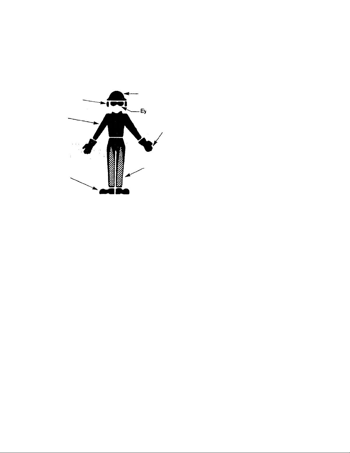
Hearing
Protection
Snug
Pitting
Clothing
Safety
Shoes
Safety Hat
'e Protection
Heavy Duty Gloves
Safety Chaps
Figure 1
KNOWYOUR SAW
• Read your operator^ manual carefully until you compietely understand and can follow all safety rules, precautions, and
operating instructions before attemptfog to operate flie unit
• Restrict the use of your saw to aduK users wiio under
stand and can follow safe^ rules, precautions, and operating
inslrudfons found in this manual.
PLAN AHEAD
• Wear protective gear. Figure 1. Always use sieel-toed safe
ty focrtwear with non-slip soles; snug-fittir^ clothing; heavy
duty, non-slip gloves; eye profectlon such as non^jgging,
vented goggles or face screen; an approved safety hard hat;
and sound barriers - ear plugs or mufflers to protect your
hiring. Renter users should have hearfag chected regular
ly as chain saw noise can damage hearing.
• Ker^ all parts of your body away from the chain when the
engine fe running.
• Keep children, by^nders, and animals a minimum of 30
feet (10 meters) away from the work area. Do not allow
other people or animate to be near the chain saw when start
ing or operating the chain saw.
• Do not handle or operate a chain saw when you are
fatigued, ill, or upset, or If you hmra taiten adcohol, drugs,
or medication. Vbu must be fa good ffaysical condition and
mentally alert. Chain saw work is strenuous. If уюи have any
concfition that m^ be aggravated by stienuous итак, check
with your doctor before operating a chain saw.
• fto not aifrempt to use your chain saw during bad weath
er condions such as strong vrfnd, rafa, snow, ice, etc., or at
night
• Carefully plan your sawing operatim in advance. Do not
start cutting until you have a clear work area, secure footyig,
and, if you are felling trees, a planned retreat path.
■ Do not operate a chain saw that is demised, improperly
adjusted, or not completety and secinely assembled.
Always r^ace the handguatd immediatdy if К becomes
damaged, brolran, or is otherwise removed.
• Keep toe handles dry, dean, and free of oil or fuel mix
ture.
• ШЬ the engine stopped, hand carry the chain saw with
the muf№r away from your body, ¿id the guide bar and
chain to the rear, prefercfoty covered a sca^id.
FUEL HANDUNG
• Eliminate all sources of sparks or ffames in 11ю areas
where fuel is mixed, poured, or stored. There should be no
smoking, open flames, or wood that could cause ^arks.
Allow engine to cool before refueling-
• Mix and pour fuel in an outcteor area on bare ground; $twe
feel in a cool, dry, well ventilated place; and use an approved,
marked container for all fuel purixises.
• Wipe up all fuel spills before starting saw.
• Move at feast 10 feet (3 meters) hem toe hiding dte
before starting toe engine.
• Do not smoke while handling fuel or white operating the
saw. .
• Turn toe engine off and let your saw cod in a non-com-
budibie area, nd on dry leaves, strav, paper, etc. Sfowty
remijve fuel cap and refoel unit
• Store the unit and fuel in an area where fuel vapors cannot
reach sparks or opwi flames from water heaters, electric'
motors or switches, furnaces, etc.
Exposure to vibrations through prolonged use of gasoline powered hand tools could cause blood vessel or nerve damage fa the fin
gers, hands, and joints erf people prone to circulation disorders or abnormal sweilings. Prolonged use in cold weather has been linked
to blood vessel damage in otherwise healthy people. i( symptoms occur such as numbness, pain, loss of strength, change in skin color
or tesdure, or loss of feelings In the fingers, trands or joints, discontinue the use of this tool and seek mecficai attention. An anti-vibra
tion system does not guarantee the avoidsmee trf these problems. Users who operate power tools on a continual and regular basis must
' monitor closely their physical condition and the condition of this unit.
SAFETYNCmCE
LOOK FOR THIS SYMBOL TO po(Nx oUT IMPORTANT SAFETY PRECAUTIONS.
A
IT MEANS - ATTENTIONiJ! BECOME ALERT!!! YOUR SAFETY IS INVOLVED.
-2-
Page 3
SAFETY RULES
OPERATE YOUR SAW SAFELY
• Do not operate a chain saw with one hand. Serious
injury to the operator, helpers, bystanders or any combina
tion of these persons rray result from one-handed opera
tion. A chain saw is intended for two-handed use.
• Oper^e flie chain saw only in well-ventifated outdoor
areas.
• Do not operate saw from a ladder or in a tree, unless
specifically trained to do so.
• Position all parts of your body to the left of cut and
away from the chain when the engine is running.
• Cut wood only. Do not use your saw to pry or shove away
limbs, roots, or other objects,
• Make sure the chain will not make contact with any
object white starting the engine. Never try to start the
saw when the guide bar is in a cut or kerf.
' Use extreme caution when cutting small size brush
and saplings. Slender material can catch the chain and
be whipped toward you or pull you off balance.
' Be alert for springback when cutting a limb that is under
tension so you will not be struck by the limb or saw when
the tension in the wood fibers is released.
Do not put pressure on the saw at the end of a cut
Aiplying pressure can cause you to lose control when the
cut is completed.
Stop ihe engine before setting the saw down.
Keep fuel and oil caps, screws, and fasteners securely
tightened.
MAINTAIN YOUR SAW IN GOOD WORKING ORDER
• Have all chain saw service performed by your Sears
Service Center with the exception of the items listed in the
“Customer Responsibilities" section of this manual. For
example, if improper tools are used to remove or hold the
flywheel when servicing the clutch, structural damage to
the flywheel can occur and cause the f^iwheel to burst.
• Make certain tiie chain stops moving when the throttle
trigger is released. For correction, refer to “Carburetor
Adjustments."
• Stop the saw if the chain strikes a foreign object
Inspect unit and repair or replace parts as necessaiy.
• Disconnect tfie spark plug before performing any
maintenance except for carburetor adjustrrwnts.
• Never modify your saw in any way. Use only SEARS '
accessories and replacement parts as recxDmrnended.
TRANSPORTING AND STORAGE
• stop the unit before transporting.
• Allow engirie to cool, cover the guide bar and chain, and
secure the unit before storing or trareporting in a trehide.
• Empty ftjel lank before storing or transporting tte unit. Use
up any fuel left in the carburetor by starting the engine and
letting ti^ engine run until it stops.
• Store unit and fuel in an area where fuel vapors cannot
reach sparks or open flames from water heaters, electric
motors or switches, furnaces, etc.
• Store unit so the chain cannot acddentally cause injury,
• Store the unit out of the reach of children.
GUARD AGAINST KICKBACK - Kickback is a dangerous reaction that can lead to serious injury.
KICKBACK WARNING;
A
KICKBACK CAN OCCUR WHEN THE MOV
ING CHAIN CONTACTS AN OBJECT AT THE
UPPER PORTION OFTHETIP OFTHE GUIDE
BAR OR WHEN THE WOOD CLOSES IN AND
PINCHES THE CHAIN IN THE CUT. CONTACT
AT THE UPPER PORTION OF THE TIP OF
THE GUIDE BAR CAN CAUSE THE CHAIN
TO DIG INTO THE OBJECT, WHICH STOPS
THE CHAIN FOR AN INSTANT.THE RESULT
IS A LIGHTNING FAST, REVERSE REACTION
WHICH KICKS THE GUIDE BAR UP AND
BACK TOWARD THE OPERATOR, IF THE
CHAIN IS PINCHED ALONG THE TOP OF
THE GUIDE BAR, THE GUIDE BAR CAN BE
DRIVEN RAPIDLY BACK TOWARD THE
OPERATOR. EITHER OFTHESE REACTIONS
CAN CAUSE LOSS OF SAW CONTROL
WHICH CAN RESULT IN SERIOUS INJURY.
DO NOT RELY ONLY ON THE SAFETY
DEVICES PROVIDED WITH YOUR SAW. AS
A CHAIN SAW USER, YOU MUST TAKE
SPECIAL SAFETY PRECAUTIONS TO HELP
KEEP YOUR CUTTING JOBS FREE FROM
ACCIDENT OR INJURY.
Figure 2
Kidtt)ack
Path
3-
Page 4
SAFETY RULES
Never Reverse
Hand Positions
Thumb On
Under Side Of
Handlebar
Elbow
Locked
Stand To
The Left
Of The Saw
Figure 4
REDUCE THE CHANCE OF KICKBACK
• Recognize ttiat kickback can happen. With a basic
understanding of kio№ack, you can reduce the element of
surprise which contributes to accidents.
• Never let the moving chain contact any object at the flp
of the guide bar. Figure 2.
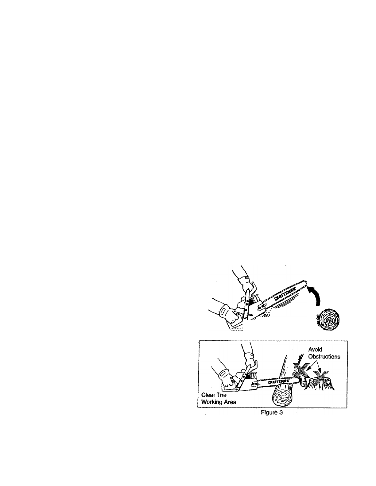
• Keep ^ woiidng area free from obstructions such as
other trees, branches, roci<s, fences, stumps, etc. Figures.
Eiitninate or avoid any obstruction that your chain could hit
v/htie you are cutting through a particular log or branch.
• Keep your chain sharp and property tensioned. A loose
or dull chain can increase the chance of kic^cback to occur.
Follow TOnufacturer’s chain sharpening and mantenance
instructions. Check tension at regular intervals with the
engine slopped, never with the engine running. Make sure
the bar clamp nuts are securely tightened after tensioning
the chain.
• Begin and continue cutting at full ttirottle. If the chain is
mowng at a slower speed, there is greater chance for kfdcback to occur.
' Cut one log at a time.
' Use extreme caution when re-entering a previous cut.
’ Do not attempt plunge cuts.
' Watdi for shifting logs or other forces that could close a
cut and pinch or fall into chain.
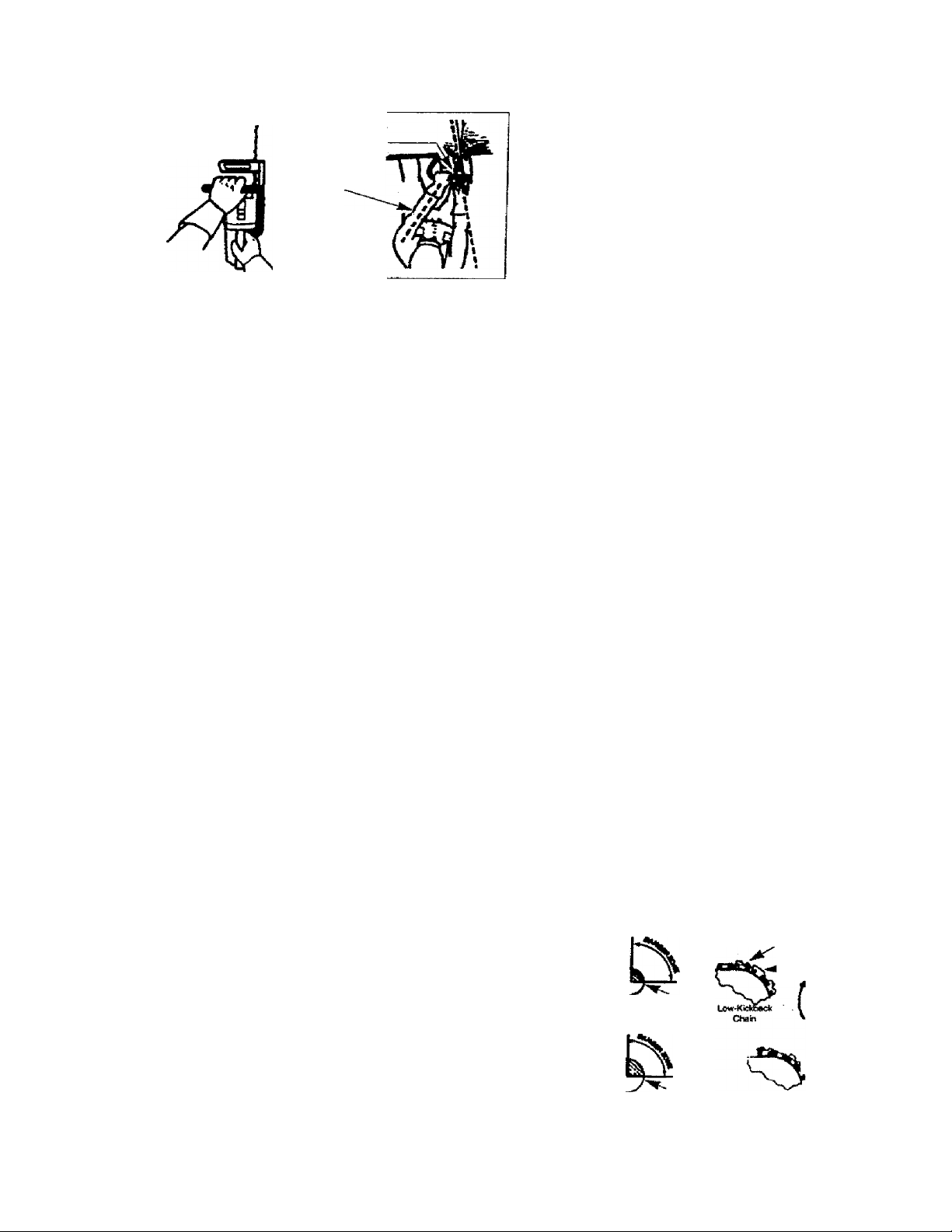
Use the Reduced-Kickback Guide Bar and LowKtckbadc Chain speeded for your saw.
KICKBACK SAFETY FEATURES
WARNING:
A
' Reduced-Kicitoack Guide Bar, designed with a small
THE FOLLOWING FEATURES ARE INCLUDED
ON YOUR SAW TO HELP REDUCE THE HAZ
ARD OF KICKBACK; HOWEVER, SUCH FEA
TURES WILL NOT TOTALLY EUMINATE THIS
DANGEROUS REACTION. AS A CHAIN SAW
USER, DO NOT RELY ONLY ON SAFETY
DEVICES. YOU MUST FOLLOW ALL SARETY
PRECAUTIONS, INSTRUCTIONS, AND MAIN
TENANCE IN THIS MANUAL TO HELP AVOID
KICKBACK AND OTHER FORCES WHICH CAN
RESULT IN SERIOUS INJURY.
radius tip which reduces the size of the' kickback danger
zorie on the guide bar tip. Rgure 5. A Reduced-Kickback
Guide Bar is one which has been demonstrated to signif
icantly reduce toe number and seriousness of kickbacks
when tested in accordance with ANSI B175.1-1991.
Low-Kickback Chain, designed with a contoured depth
gauge and guard link which deflect kickback force and
allow wood to gradually ride into the cutter. Figure S. LowKickback Chain is chain which has met kickback perfor
mance requirements of ANSI B175.1-1991 when tested
on a representative sample of chain saws below 3.8 cubic
MAINTAIN CONTROL
• Keep a good, finn grip on the saw with both hands
when the engine is running and don’t let go. Rgure 4.
A firm grip can neutralize kickback and he^ you maintain
control of the saw. Keep the fingers of your left hand encirding and your left thumb under the front handlebar. Keep
your right hand comptetety around the rear handle whether
you are right handed or left handed. Ifeep >our left arm
straight vrith the elbow locked.
• Position your left hand on the front handlebar so it is
in a sbaight line with your right hand on the rear han
dle when mafdng bucMng cuts. Figure 4. Never reverse
right and left hand positions for any tjpe of cutting.
• Stand with your weight evenly taianced on both feet
• Stand slightly to the left side of toe saw to keep your
body from being in a direct line vnth toe cutting chain.
Figure 4.
• Do not overreach. You could be drawn or thrown off bal
ance and tose control of the saw.
• Do not cut above shoulder he^ht It is difflojft to main
tain control of saw above shoulder height
UNDERSTANDING REACTIVE FORCES
Pindi-Kickback and Pull-In occur when tire chain is sud-
derdy stopped by being pinched, caught, or by contact
ing a foreign object in the wood. This stopping of the chain
results in a reversal of the chain force used to cut wood and
causes the saw to move in the opposite direction of tiie chain
rotation. Either reaction can resuit in toss of control and pos
sible serious injury.
• PindvKickbadc
- occurs when chain on lop of guide bar is suddenly
stopped.
- rap/y/y drives saw straight bad< toward operator.
• PulHn
- occurs when the chain on the bottom of the guide bar is
suddenly stopped.
- pulls the saw rapidly forward.
inch displacement specified in ANSI B175.1-1991.
’ Handguard, designed to reduce the chance of your left
hand contactiog the.chain if your hand siips off the front
handlebar.
Position of front and rear handlebars, designed with
distance between handles and “in-line" wth each other.
The spread and “iri-line" position of the hands provided
this design work together to give balance and resistance
in contioliing the pivot of the saw back toward the opera
tor if kickback occurs.
ANSI B175.1-1991 — Saiety requireinonts for gasoline powered chain
saws as set by the American Nation^ Siandands Institute, inc.,
StarKiaiT!B175.1-1991.
Contoured
fta^iuceii iGckbiick
Symmefneaf Gukde Bar
Senatr
Radius Tip
Odp№ G augo
Chain With HI01
Kk^bacfc Foter^tai
Flongat ad
^GuideU nlc
Oedect e
Kidcbadk Force
Aid Allows Wood
ToGraduaftyRkfe
tnfo Cutter
Obstruct
Material
Figure 5
Page 5

CONGRATULATIONS on your purchase of a Sears
Craftsman Gasoline Chain ^w. It has been designed,
engineered and manufactured to give you the best possi
ble dependability and performance.
Should you experience any problems you cannot easily
remedy, please contact your nearest Sears Service Cen-
ter/Department or call the 1 -800 number listed on the front
of this manual. Sears has competent, well trained techni
cians and the proper tools to service or repair this unit.
Please read and retain this manual. The instructions will
en^le you to assemble and maintain your unit properly.
Always observe the “SAFETY RULES.”
MODEL NUMBER:
358.3S1080 -18"
358.351160-16"
358.351180-18“
DATE CODE/SERIAL NO.:
DATE OF PURCHASE:
THE MODEL AND SERIAL NUMBER WILL BE
FOUND ON THE PRODUCT.
YOU SHOULD RECORD BOTH SERIAL NUMBER
AND DATE OF PURCHASE AND KEEP IN A SAFE
PLACE FOR FUTURE REFERENCE.
MAINTENANCE AGREEMENT
A Sears Maintenance Agreement is available on this prod
uct. Contact your nearest Sears Store for details.
CUSTOMER RESPONSIBILITIES
• Read and observe the safety rules.
• Follow a regular schedule in maintaining, caring for, and
r using your unit,
• Follow the instructions under “Customer Responsibi
lities” and “Storage” sections of 8iis Operator's Manual.
PRODUCT SPECrFICATlONS
GUIDE BAR:...............
. 16"
18"
CHAIN:
.......................
Low Profile 3/8" Pitch
Chrome Cutteis
DISPLACEMENT:
2.4 Cubic Inches (40cc)
.......
2.6 Cubic Inches (42cc)
ENGINE:.....................
FUEL MIX:
OILER:
IGNITION:
..................
........................
....................
2-cycle Air Cooled
40:1 (3.2 oz.oil per gallon gas)
Automatic, 6.8 oz.Tank
Solid State
(Air gap .010* to .014")
IGNITION TIMING:
SPARK PLUG TYPE:..
SPARK PLUG GAP:....
MUFFLER;
ENGINE RPM:..
Your saw Is equipped with a tenipetature limiting muf
fler and spark arresting screen which meets the require
ments of California Codes 4442 and 4443. All U.S. forest
...................
............
Non-adjustabte, fixed
.......
Champion (CJ-7Y)
.025" <.65mm)
Spark Arresting Screen
12,600 RPM Maximum
SPECIAL NOTICE
land and the states of CalHdmia, Idaho, Maine, Mtnnescrta,
New Jersey. Washington, and Oregon require many internal
combustion engines to be equip^fod with a spark arrestor
screen by law.
If you open^e a chain saw In a state or lociUe where
suc^ regulations exist, you are legally responsible for
maintaining the operating condition of these parts.
Failure to do so is a violation of the law. Refer to the
Spark Arrestor section under “Customer Responsibiiitfes”ldr maintenance.
MANUFi«CTUREO UKDER ONE OR MORE OF WE FOaOWlNG US. FOTEIiTS;
E,3S7,SS3:4.9<l0.0a8; 4,370.KS; i.30Z.87S; 4.197.640; DKS.330.0IMÊR Ü.3. AND FOR-
BQN PATENTS PENDING.
SPECIAL NOTICE
If this saw is to be used for commercial logging, must order and install a Chain Brake, to comply
with Federal QSHA Reguiations for Commercial Logging see Repair Parts List or call 1-800-235-5878.
FULL ONE YEAR WARRANTY ON CRAFTSMAN GAS CHAIN SAW
V •
For one year from the date of purchase, when this Craftsman Gas Chain Saw is maintained, lubricated and tuned-up
according to the owner’s manual, Sears will repair, free of charge, any defect in material or workmanship.
This warranty excludes the bar, chain, spark plug and air filter, which are expendable parts, and become worn during
normal use.
If this Gas Chain Saw is used for commercial or rental purposes, this warranty applies for 30 days from the date of pur
chase.
WARRANTY SERVICE fS AVAILABLE BY RETURNING THIS CHaIn SAW TO THE NEAREST SEARS SERVICE
CENTER IN THE UNITED STATES.
This warranty gives you specific legal rights, and you may also have other rights which vary from state to state.
SEARS, ROEBUCK AND CO., D/817WA, Hoffman Estates, IL 60179
-5-
Page 6
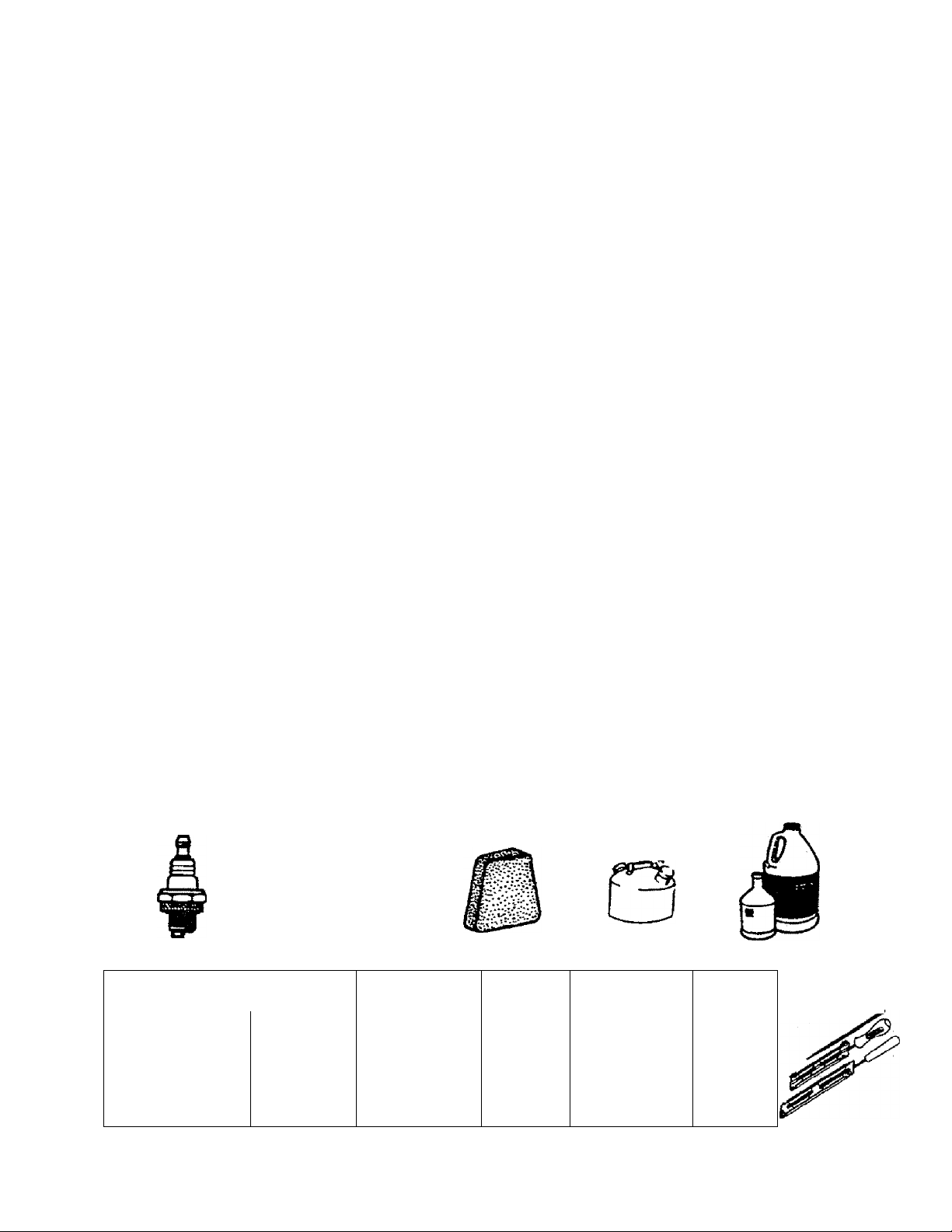
TABLE OF CONTENTS
Safety Rules....................................................................,2
Product Specifications...........................;
Warranty................................................................... 1.....5
Accessories
Operation............................................
Customer Responsibilities
Accessories.
Air Filter
Bar and Chain Oil
Bucking
^ C
Carburetor Adjustments ................................................
Carton Contents.
Chain Adjustment
Chain Oiler
Chain Sharpening
Customer Responsibilities
Spark Plug
Engine
FueVOil........................................................................10
Spark Plug
Starting
Storage....................................................................... 27
Fuel Filter
Fueling
Guide Bar and Chain Oil.,.,,............................................ ю
Guide Bar Maintenance
How To Use Your Chain Saw............................................ g
........................................
....................................
...................................................................
.......................................................................
В
...........................................................................
.................................................................
......................................................................
.................................................................
................
..................................................
.................
................................................................... 9
........................................................
.................................................................
...........................................
................................................. 19
.......................................... 10
..............
................................
E
F
G
H
.........................
„ . 6
.......17
20
.........
.......Z....1....*. З2
....Z.ZZZZZZIZIZI20
................7
ig
20
"['.'11
21
*"L...l"!lO
„5
INDEX
e
.
25
. Tree Felling
Service and Adjustments............................................
Storage......................................................................... 27
Trouble Shooting Points.................................................28
Repair Parts.................................................................. 29
Repair Parts Ordering/Service
Know Your Chain Saw..................................................... 8
Limbing......................................................................... 16
Maintenance Schedule....................................................17
Model Number
Muffler.............................................................................20
Operation
Ordering Repair Parts
Product Specifications
Pruning......................................................................... 16
Repair Parts..
Service and Adjustments
Spark Arrestor Screen......................................................20
Starter Rope................................................................. 23
Starting.........................................................................
Storage........................................................................ 27
Throttie Control Group
Trouble Shooting Points
Warranty...........................................................................S
.............................................................. 5
...........
.........
...............................................
........................................
............................................. ......5
............................................................
......................................................
...................................................... ........13
...........................
K
L
O
P
R
S
................................................
T
.............................................
W
,...22
Back Cover
..,.,.,.....,.8
Back Cover
.....29
11
28
22
9
ACCESSORIES
These accessories and attachments were available when the unit was originally purchased.They are also available at rtrast
Sears retail outlets and service centers. Most Sears stores can order these items for you when you provide the model num
ber of your unit. ^ .
PERFORMANCE
Spark Plug
MAINTENANCE
Carr^ng
Case -------------X
Я
40:1
3.2 ог
1 Gloves
2-cycle
Engine
Oil
W
3.2 oz.
80Z.
16 oz.
Guide Bar
/W
/w
Air RIfer
Ш
Safely
Goggles
Gas Can Bar Oil
Iqt.
1 gal.
Chain
Hearing
Protection
Chain
Sharpener
Ч
Page 7
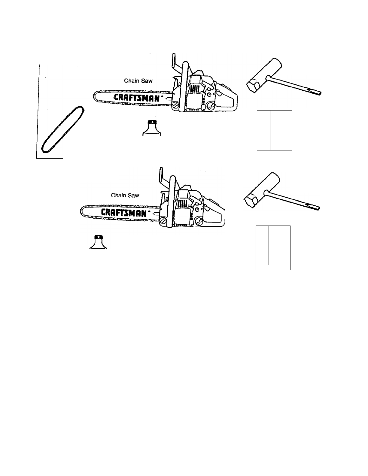
..хШ
: -:.j
MODEL 358.351080 - 18" ONLY
EXTRA CHAIN
Extra Chain
MODEL 358.351160 -16" MODEL 358.351180 -18"
CARTON CONTENTS
Fuel/Oil Mix
40:1
3J!OZ.
(Bar Oil not included)
Purchase Craftsitian Bar
and Chain Oil Separately
Bar Tool
Operator’s Manual
Bar Tool
Fuel/Oil Mix
(Bar Oil not included)
Purchase Craftsman ^r
and Chain Oil Separately
TOOLS REQUIRED FOR SERVICE
• Torque Wrench (optional) - Reference torque values are
provided throughout this manual for tightening hardware.
• Bar Tool (included)
TO REMOVE CHAIN SAW FROM CARTON
• Remove loose parts bag included with Chain Saw.
• Remove your saw from the packing material.
• You may use the opened packing material as a vwirk sur
face-
Operator’s Manual
• After removing the contents from the carton, check parte
against the Carton Contents.
• Examine the parts for damage. Do not use damaged
parts.
• ff parts are missing or damaged please cal! the 1-800
number listed on the front of this manual.
NOTE; It is norma! to hear the fuel filter rattle in an empty
fuel tank.
-7-
Page 8
OPERATION
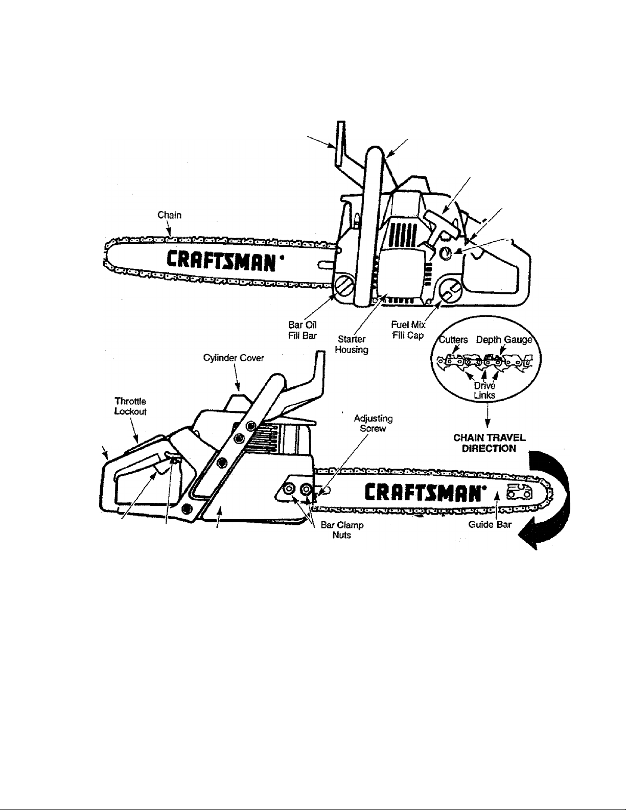
KNOW YOUR CHAIN SAW (Fig. 6)
READ THIS OPERATOR’S MANUAL AND SAFETY RULES BEFORE OPERATING YOUR CHAIN SAW. Compare the Illus
trations with your unit to familiarize yourself with the location of the various controls and adjustments. Save this manual for
future reference.
Front
Hand Guard
Handle
Starter
Rope Handle
On/Stop
Switch
. Primer
Rear
HarKJIe
TTirottle
Trigger
in accordance wiUi American National Standards for Gasoline-Powered Chain Saws Safety Requirements
___________________________________(ANSI B17S.1-1991).
The ON/STOP SWITCH is used to stop the engine.
The STARTER ROPE HANDLE Is used for starting the
engine.
The CHOKE KNOB activates the choke to provide addi
tional fuel to the engine when starting a cold engine.
The THROTTLE LOCKOUT prevents the THROTTLE
TRIGGER from being squeezed accidentally.
The THROTTLE TRIGGER controls engine speed.
Choke
Knob
Bar Clamp
Figure 6
Listed by Underwriters Laboratories, Inc.
The GUIDE BAR is designed to carry the chain.
The CUTTERS are designed to cut the wood.
The BAR CLAMP NUTS are designed to hold the guide
bar after adjustments have been completed.
The ADJUSTING SCREW is designed to tension the chain
on the guide bar.
The PRIMER BULB circulates fuel to the carburetor.
8-
Page 9
OPERATION
HOWTO USE YOUR CHAIN SAW
STOPPING YOUR ENGINE
• Move on/stop switch to the "Stop" positron.
• If engine does not slop, pull blue choke knob out fully.
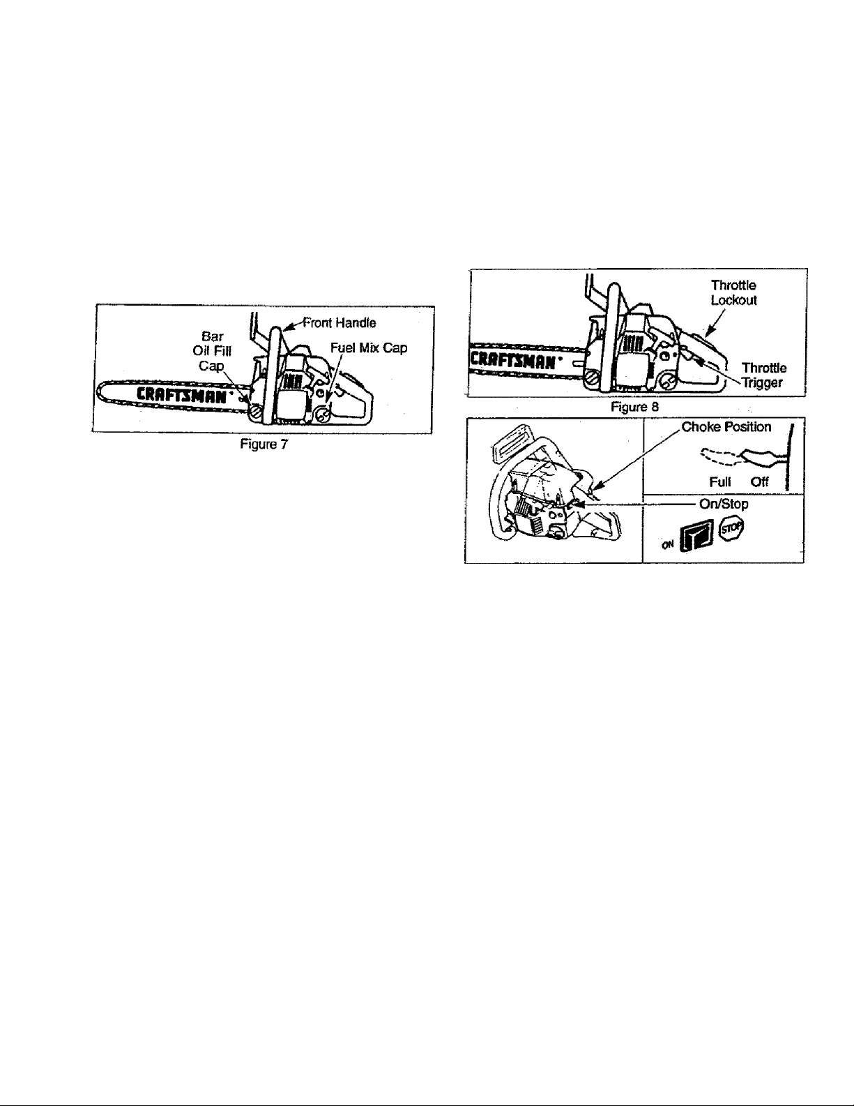
CHAIN OILER {Fig. 7)
• The chain oiler provides continuous lubrication to the
chain and guide bar. Be sure to fill the bar oil tank when
you till the fuel tank (Capacity 6.8 fl, oz.).
• Your chain saw will consume approximately one tank of
bar oil for each tank of fuel used.
Your chain oiler is automatic and requires no adjustment.
THROTTLE CONTROL GROUP (Fig. 8)
THROTTLE LOCKOUT
• The throttle lockout prevents unintentional actuation of
the throttle trigger.
• You must depress the throttle lockout with the palm of
your hand before actuating the throttle trigger,
CHOKE/FAST IDLE SPEED
• The choke and fast idle speed are set by pulling the
choke lever out fully for cold or refueled engine starts.
• Squeezing the throttle trigger will release the dioke and
fast idle settings. If the throttle trigger is squeezed acci
dentally during starting, it will be necessary to reset
throttle advance by pulling choke lever out fully.
• The choke provides additional fuel when starting a cold
engine.
• The choke is actuated by pulling the blue choke knob.
• The choke has two positions: off and full.
THROTTLE TRIGGER
• The throttle trigger allows for varicdsle control of engine
speed.
• The throttle trigger is actuated by the index finger on your
right hand. (After the throttle lodcout is depressed).
Figure 9
9-
Page 10

OPERATION
BEFORE STARTING ENGINE
WARNING:
A
GUIDE BAR AND CHAIN OIL
For maximum guide bar and chain life, we recommend you
use Craftsman chain saw bar oil. If Craftsman bar oil is hot
available, you may use a good grade SAE30 oil until you are
able to obtain Craftsman brand. The oil output is automati
cally metered during operation. Your saw wifi use approxF
rnately one tank of bar oil for every tank of fuel mix. Always
fill the bar oil lank when you fill the fuel tank.
GASOLINE
The two-cycle engine on this product requires a fuel mixture
of regular unleaded gasoline and a quality 40:1
2-cycle engine oil (AIR-COOLED) for lubrication of the bear
ings and other moving parts. The correct fuel/oit mixture is
40:1 (see Fuel Mixture Chart).Too little oil or the irxxjtrect oil
ti^e will cause poor performance and may cause the engine
to overheat and seize.
Gasoline and oil must be piemixed in a clean approved fuel
container. Always use fresh regular unleaded gasoline.
This engine is certified to operate on unieaded gasoline.
IMPORTANT: Experience indicates that alcohol blended
fuels called gasohol (or using ethanol or methanol) can
attract moisture, which leads to oil/gas separation and for
mation of acids during storage. Actdfc gas can damage the
fuel system of an engine while in storage. To avoid engine
problems, the fuel system should be emptied before storage
for 30 days or longer. Drain the gas tank, then run the fuel
out of the carburetor and fuel lines by starling the engine
and letting it run until it stops. Use fresh fuel next season.
BE SURE TO READ THE FUEL HANDLING
INFORMATION IN THE SAFETY RULES
SECTION ON PAGE 2 OF "mis MANUAL
BEFORE YOU BEGIN.
IF YOU DO NOT UNDERSTAND THE FUEL
HANDLING SECTION DO NOT ATTEMPT TO
FUEL YOUR UNIT; SEEK HELP FROM
SOMEONE THAT DOES UNDERSTAND THE
FUEL HANDLING SECTION OR CALL THE
CUSTOMER ASSISTANCE HOTLINE AT
1-800-235-5878.
FUEL STABIUZER
Fuel stabilizer is an acceptable alternative in minimizing the
formation of fuel gum deposits during storage. Add stabiliz
er to gasoline in fuel lank or storage container. Always fol
low the fuel mix ratio found on the staMlizer container. Run
eni^ne at least 5 minutes after adding stabilizer to allow the
stabilizer to reach the carburetor. Yju do not have to drain
the fuel tank for storage if you are using fuel stabilizer.
CRAFTSMAN 40:1 2-cycte engine oil (AIR-COOLED) is
specially blended with fuel stabilizers. It you do not use this
Sears oil, can add a fuel stabilizer to your fuel tank.
40:1 2-CYCLE AIR-COOLED ENGINE OIL
CRAFTSMAN 40:1 2-cycle engine oil (AIR-COOLED) is
strongly recommended. This oil is specificaily blended vwth
fuel stabilizers for increased fuel stability (extends fuel life
up to 5 times longer) and reduced smoke.
If CRAFTSMAN 40.T 2-cyde engine oil (AIR-COOLED) is
not available, use a good quality 2-cyc!e engine oil (AIR
COOLED) that has a recommended fuel mix ratio of 40:1.
IMPORTANT! Do not use:
• AUTOMOTIVE OIL
• BOAT OILS (NMMA, BIA, etc.)
These oils do not have proper additives for 2-cycle
(AIR-COOLED) engines and can cause engine damage.
GASOLINE AND OIL MIXTURE
MIX GASOLINE AND OIL AS FOLLOWS:
• Consult chart for correct quantities,
• Do not mix gasoline and oil directly in the unit’s fuel tank.
FOR ONE GALLON:
• Ffour 3.2 ounces of high quality, 40:1 2-cycie engine oil
(AIR-COOLED) into an empty, approved one gallon
gasoline rxjntainer.
• Add one gallon of regular unleaded gasoline to the gallon
container, then securely replace the cap.
• Shake the contalnerrmmentarily.
• The mixture is now ready for use. Fuel stabilizer can be
added at this tforre if desired; follow mixing instructions on
the label.
FUEL MIXTURE CHART
use engine or carburetor cleaner products in the fuel tank or
permanent damage may occur.
G.8Sfllioe
1 gallon
2.5 gallons 8.0
NOTE: Fuel containers may hold more than the ^Mcrfted
amount. If too muc^ gasoline is in the container, the result
ing gas-to-ofl fuel mixture will not be correct for proper
engine operation.
Oil ffl.oz.f
3.2
10
Page 11

3»=3S;
•У-iXSS
, ;.л
OPERATÍON
STOPPING YOUR ENGINE
• Move on/stop switch to the “Stop” position.
• if engine does not stop, pull blue choke knob out fully.
WARNING:
ALWAYS WEAR GLOVES, SAFETY FOOT
WEAR, SNUG-FITTING CLOTHING, AND
EYE, HEARING, AND HEAD PROTECTION
DEVICES WHEN OPERATING A CHAIN SAW.
THE CHAIN MUST NOT MOVE WHEN THE
ENGINE RUNS AT IDLE SPEED. REFER TO
THE "CARBURETOR ADJUSTMENTS” SEC
TION FOR CORRECTION.
AVOID ANY CONTACT WITH THE MUFFLER.
A HOT MUFFLER CAN CAUSE SERIOUS
BURNS.
NOTE: Check chain tension using insfructions in the
“Service and Adjustment” section.
• Before first use.
• After 1 minute of operation.
TO SmRT ENGINE (Fig. 10 & 11)
COLO ENGINE START AND WARM ENGINE
START AFTER RUNNING OUT OF FUEL
• Fuel engine with 40:1 fuel mix (3.2 oz. to 1 ga(. gas).
• Fil! bar oil tank with bar oil. Your saw wifi use approxi
mately one tank of bar oil for each tank of fuel mix.
• Prime engine by pressing primer bulb six times.
• Turn on ignition by moving on/stop switch to the "On”
position.
• Pufi the blue choke/fast idle control out fully to set both
the choke and fast idle for starting. Then set the saw on
the ground. Grip the front handle with your left hand and
place your right foot through the opening in the rear han
dle,
• IFTHROTTLETRIGGER IS SQUEEZED ACCIDENTAL
LY DURING STARTING IT WILL BE NECESSARY TO
RESET THE CHOKEfFAST IDLE CONTROL,
NOTE: When pufiing the starter rope, do not use the full
extent of the rope as this can cause the rope to break. Do
not let the starter rope snap back, hold the handle and let
the rope rewind slowly.
• Pull starter rope handle with your right hand until the
engine attempts to start. Then push the blue choke knob
in to the partial position. Resume puiling handle until
engine starts.
• Above 40 degrees, allow engine to run for approximate
ly 5 seconds, push the choke knob in to the “Off” posi
tion, then squeeze and release throttle trigger to allow
engine to idle.
• Below 40 degrees, allow engine to warm up 30 seconds
- 1 minute with choke at partial position. Push choke
knob in to the "Off” position, then squeeze and release
throttle trigger to allow engine to idle.
• To stop engine, move on/stop switch to the “Stop” posi
tion.
Figúrelo
STARTING A WARM ENGINE
• Move on/stop switch to the X>h* position.
• Engage the choke/feist idle by pulling out the blue choke
knob fully and pushing it back in fully.
• Be sure choke is in the “Off” position.
• With saw on ground, grip front handle with left hand and
place your right foot through opening in rear handle.
• Pull starter rope handle until engine starts.
• Squeeze and release throttle trigger to return engine to
idle speed.
DIFFICULT STARTING OR FLOODED ENGINE
The engine may be flooded with too much fuel If it has not
started after 10 pulls.
Flooded engines can be cleared of excess fuel with the fol
lowing procedure:
• Pull out the blue choke/fast idle control fully and then
push it back into the *C5ff ” position to set the fast idle con
trol to the start position.
• Verify that the on/stop switch is in the “On" position.
• Push the choke knob to the “Off” position.
• With saw on ground, grip front handle with ieft hand and
place right foot through opening in rear handle.
• Pull starter rope handle until engine starts.
Starting could require pulling starter rope handfe many
times depending on how badly unit is flooded. If engine still
fails to start, refer to “TROUBLE SHOOTING" diart or call
the 1-800 number listed on the front page of this manual.
-11 -
Page 12

OPERATION
GENERAL OPERATION TIPS
• Cut wood only. Do not cut metal; plastics; masonry; non
wood building materials; etc.
• Stop trie saw if the chain strikes a foreign object. Inspect
the saw and repair or replace parts as necessary.
• Keep the chain out of dirt and sand. Even a small amount
of dirt will quickly dull a chain and thus increase the pos
sibility of kickback.
To get the “feel” of using your saw before you begin a major
sawing operation, practice cutting a few small logs using
the following technique:
• Accelerate engine to full throttle by squeezing the throttle
trigger before entering cut.
OPERATION SAFETY
WARNING:
IF SAW BECOMES PINCHED OR HUNG IN A
LOG, DO NOT TRY TO FORCE IT OUT, YOU
CAN LOSE CONTROL OF THE SAW
RESULTING IN INJURY AND/OR DAMAGE
TO THE SAW. STOP THE SAW, DRIVE A
WEDGE OF PLASTIC OR WOOD INTO THE
CUT UNTIL THE SAW CAN BE REMOVED
EASILY. RESTARTTHE SAW AND CAREFULyr REENTER THE CUT. TO AVOID KICK-
DAMAGE, DO NOT USE A
METAL WEDGE. DO NOT ATTEMPT TO
RESTART YOUR SAW WHEN IT IS PINCHED
OR HUNG IN A LOG.
KICKBACK CAN OCCUR WHEN THE MOV
ING CHAIN CONTACTS AN OBJECT AT THE
UPPER PORTION OFTHETIP OF THE GUIDE
BAR OR WHEN THE WOOD CLOSES IN AND
PINCHES THE SAW CHAIN IN THE CUT.
CONTACT ATTHE UPPER PORTION OFTHE
TIP OF THE GUIDE BAR CAN CAUSE THE
CHAINTO DIG INTOTHE OBJECT AND STOP
THE CHAIN FOR AN INSTANT. TOE RESULT
IS A LIGHTNING FAST, REVERSE RÉACTION
WHICH KICKS TOE GUIDE BAR UP AND
BACK TOWARD THÉ OPERATOR. IF THE
SAW CHAIN IS PINCHED ALONG THE TOP
OF THE GUIDE BAR, THE GUIDE BAR CAN
BE DRIVEN RAPIDLY BACK TOWARD THE
OPERATOR. EITHER OFTHESE REACTIONS
CAN CAUSE LOSS OF SAW CONTROL
WHICH CAN RESULT IN SERIOUS INJURY.
• Never cut with engine at partial speeds.
' Begin cutting with the saw chassis against the log.
> Keep engine at full throttle during cutting procedure.
• Allow the chain to cut for you; exert only light downwrard
pressure. If you force the cut, damage to №e bar, chain,
or engine can result.
Release the throttle trigger as soon as the cut is com
pleted, allowing the engine to idle. If you run the unit at
full throttle without cutting, unnecessary wear can occur
to the chain, bar, and engine.
To avoid losing control when completing the cut, do not
put pressure on the saw during the end of the cut.
Stop engine before setting unit down after operation.
AVOID REACTIVE PINCH FORCES
Pinch-Kickback and Pufl-ln occur when the chain is sud
denly stopped by being pinched, caught, or by contacting
a foreign object in the wood. This sudden stopping of the
chain results in a reversal of the chain force used to cut
wood and causes the saw to move in the opposite direction
of the chain rotation. Pinch-Kickback drives the saw
straight back toward the operator: Pull-In pulfs the saw
away from the operator. Either reaction can result in loss of
control and possibly serious injury.
TO AVOID PfNCH-KICKBACK:
• Be extremely aware of situations or obstructions that can
cause materia! to pinch the top of or otherwise stop the
chain.
• Do not cut more than one log at a time.
• Do not twist the saw as the bar is withdrawn from an
under-cut when bucking.
TO AVOID PULL-IN:
• Always begin cutting with the engine at full throttle and
the saw housing against wood.
• Use wedgesjpadejof plastic or wood, (never of metal) to
hold the cut open.
-12
Page 13

OPERATION
TREE FELLING
WARNING:
A
DETERMINE THE NATURAL FALL DIRECTION
• Wind - A tree evenly balanced will iail in the same direc
tion the wind is blowing.
• Lean - Use a carpenter’s level or plumb bob to deter
mine if tree has a natural lean. A leaning tree will tend to
fell in direction of lean.
• Shape - A tree will tend to fail towards side that is more
heavily branched.
• Other Factors - Contacting or nearby trees, buildings, or
wires can influence the direction the tree will fell.
CUTTING PROCEDURE (Fig. 12)
After determining the Natural Fail Direction, the tree should
be cut as follows;
IMPORTANT: BEFORE FELLING A TREE, MAKE SURE
YOU HAVE AT LEAST 3 FELLING WEDGES AND A
MAUL (HAMMER) AVAILABLE FOR USE IF NEEDED.
• Use some means to visually mark the Natural Fail
Direction.
• Mark your notch cut on the Natural Fail Direction side of
the tree approximately 18-24 inches above the ground.
• Cut top of the notch first at a 45 degree angle. Saw
through of the width of the tree.
• Cut bottom of the notch at a 45 degree angle until you
meet the top notch cut Remove notch of wotxl.
• On the side of the tree opposite the notch cut, make the
felling cut. The felling cut should be 2 inches afaoira the
center point of the notch cut. Before the felling cut is
complete, use wedges to open the cut when necessary
to control the direction of the fell. Use wood or plastic
wedges, but never steel or iron, to avoid kickback and
chain damage.
» Cracking sounds, widening of the felling cut, movement
in the upper branches are all signs that the tree is ready
to fell.
' As tree begins to fell, turn off saw, and move quickly
away from direction of fall.
IF THE TRUNK OR LIMBS ARE ROTTING,
THEY CAN FALL UNEXPECTEDLY AND
CAUSE SERIOUS INJURY.
AS YOU MAKE YOUR FELLING CUT, IF THE
SAW APPEARS TO BE BINDING, THE TREE
IS STARTING TO FALL IN THE WRONG
DIRECTION. IMMEDIATELY STOP THE SAW
AND USE A FELLING WEDGE AND MAUL
(HAMMER) TO FORCE THE FELLING CUT
OPEN. THE WEDGE WILL HOLD THE
FELLING CUT OPEN ALLOWING YOU TO
REMOVE THE SAW. KEEP EVERYONE AWAY
FROM THE TREE IN ALL DIRECTIONS.
•
If your chain saw binds in the felling cut, you have three
options:
• If the wrong direction of fail is acceptable, carefully
remo\ra the felling wedge.Cut deeper in the notch side of
the tree untH tree starts to fall.
• If the wrong direction of fall is not acceptabie, attempt to
use one or more felling wedges to force the tree in the
original direction of fall. Do so by driving the wedges
deeper into the felling cut.
• Keep everyone away from the tree in all directions and
then seek professional help!
FELLING TIPS
• Clear the work area of debris where you can have secure
footing.
• Make sure there is enough room for the tree to fall.
Maintain a distance of 2 1/2 tree lengths from the near
est person or other objects. Engine noise can drown out
a warning call.
• Remove dirt, stones, loose bark, nails, staples, and wire
from the tree where cuts are to be made.
• Plan to stand on the up-hill side when cutting on a slope.
• Plan a clear retreat path to the rear and diagonal to the
line of fall,
• Large buttress roots should be removed prior to notch
cut.
• Use a wedge if there is any chance that the tree will not
fall in the desired direction.
• We recommend you cut branches below shoulder height
before felling tree. (See Limbing and Pruning).
Be alert to signs that the tree Is ready to fall:
• Cracking sounds.
• Widening of the felling cut.
• Movement in the upper branches.
-13
Page 14

FELLING SAFETY
OPERATION SAFETY
DONT PUTYOURSELF INTHESE POSITIONS
Check the wind -
Don’t cut down wind
WARNING:
A
* Lodk for decay and rot If the trunk is rotted, it can snap
and fall toward the operator.
* Check for broken or dead branches which can fall on
you while cutting.
* Be extremely cautious with partially fallen trees that may
be poorly supported. When a free doesn't fall completely,
set the saw aside and puli down the tree with a cable
wirtch, block and tackle, or tractor. To avoid Injury, do not
cut down a partially fallen tree with your saw.
DO NOT CUT:
- NEAR ELECTRICAL WIRES OR
BUILDINGS.
- IF YOU DO NOT KNOW THE DIRECTION
OF TREE FALL.
- AT NIGHT.
- DURING BAD WEATHER - RAIN, SNOW,
STRONG WIND, ETC.
:
Check the lean -
Don't cut on down side Don't cut on weighted side
Check the balance
14
Page 15

OPERATiON
vm
BUCKING
Bucking is cutting a fallen tree to the desired log si2e.
TYPES OF CUTTING (Fig. 13)
• Overcutting - begin on the top side of the log with the
bottom of the saw chassis against the log; exert light
pressure downward.
* Undercutting - begin on the underside of the log with the
top of the saw chassis against the log; exert light pres
sure upward. During undercutting, the saw will tend to
push back at you. Be prepared for this reaction and hold
the saw firmly to maintain control.
Undercut
Saw Chassis
F^ure 13
BUCKING ON THE GROUND (Fig. 14)
• Overcut with a 1/3 diameter cut.
• Roll log over and finish with an overcut.
BUCKING USING A SUPPORT (Fig. 15 & 16)
Another log or a stand, such as a sawhorse, may be used
as supports when bucking.
• Area A - Undercut 1/3 of the way through the log.
- Finish with an overcut.
• Area B - Overcut 1/3 of the way through the log.
- Finish with an undercut.
BUCKING SAFETY
WARNING:
A
Stay on uphill side of tree when cutting.
DO NOT STAND ON THE LOG BEING CUT,
ANY PORTION CAN ROLL CAUSING LOSS
OF FOOTING AND CONTROL,
NEVER TURN THE SAW UPSIDE DOWN TO
UNDERCUT. THE SAW CANNOT BE CON
TROLLED IN THIS POSITION.
BUCKING TIPS
• Cut only one log at a time.
• Cut shattered wood very carefully. Sharp pieces of wood
OiUld be flung toward the operator.
• Use a sawhorse to cut small logs. Never allow another
persott to hold the log while cutting and never hold the
log with your teg or foot.
• Do not cut in an area where logs, limbs, and roots are
tangled such as in'a blown down area. Drag the logs Into
a clear area before cutting by pulling out exposed and
cleared logs first
• Give special attention to logs under strain to prevent the
saw from pinching. Make the first cut on the pressure
side to relieve the stress on the fog.
OPERATiON SAFETY
Use Common Sense
MM
Maintain Secure Footing
-15
Page 16

OPERATfON
PRUNING AND UMBING
Pruning is removing branches from a standing tree.
Limbing is removing branches from a felfed tree.
UMBING (Fig. 17)
• Start at base of the felled tree and work toward the top.
• Leave the larger limbs underneath the felled tree to
support the tree as you work.
PRUNING {Fig. 18)
Small branches - smaller than width of guide bar.
Large branches - larger than wridth of guide bar.
• Remow small limbs with one cut.
• Remove lar^r, supporting branches with the 1/3 - 2/3
cutting techniques described in the bucking section.
PRUNfNG PROCEDURE
• Cut 1 - Undercut 1/3 of the way through the limb near
the trunk of the tree.
• Cut 2 - Finish with an overcut farther out from the trunk
untii the limb falls. Keep out of the way of the falling littfa.
• Pruning Cut - Cut the limb stump flush at the edge of
the collar.
PRUNING AND LIMBING TIPS
• Work slowly, keeping both hands firmly gripped on the
saw. Maintain secure footing and balance.
• Keep a clear work area. Frequently clear branches out of
the way to avoid topping over faem.
• Leave the larger limbs underneath the felled tree to sup
port the tree as you work.
• Start at the base of the felled tree and work toward the
top.
• Keep the tree between you and the chain. Cut from the
side of frie tree opposite the branch you are cutting.
• Limit pruning to limbs shoulder height or below.
• Keep out of the way of the falling limb.
OPERATION SAFETY
PRUNING AND UMBING SAFETY
WARNING:
A
NEVER CLIMB INTO A TREE TO LIMB OR
PRUNE UNLESS SPECIRCALLY TRAINED
TO DO SO. DO NOT STAND ON LADDERS,
PLATFORMS, A LOG, OR IN ANY POSITION
WHICH CAN CAUSE YOU TO LOSE YOUR
BALANCE OR CONTROL OF THE SAW.
BE ALERT FOR AND GUARD AGAINST
KICKBACK. DO NOT ALLOW THE MOVING
CHAIN TO CONTACT ANY OTHER BRANCH
ES OR OBJECTS AT THE NOSE OF THE
GUIDE BAR WHEN LIMBING OR PRUNING.
ALLOWING SUCH CONTACT CAN RESULT
IN SERIOUS INJURY.
DO NOT CUT IF BRANCHES ARE HIGHER
THAN YOUR SHOULDER. GET A PROFES
SIONAL TO DO THE JOB.THIS MAY RESULT
IN SERIOUS INJURY. ;
Watch out for springpoles. Use extreme caution when
cutting small giSe lirfibs. Slender material may catch the
saw chain and be whipped toward you or pull you off
balance.
Be afert for springback. Watch out for branches that are
bent Of under pressure as you are cutting to avoid being
struck by the branch or the saw when the tension in the
wood fibers is released.
16-
Page 17

CUSTOMER RESPONSIBILITIES
MAINTENANCE SCHEDULE
Fill in dates as you complete regular service
Check for damaged or worn parts
Check for loose fasteners and parts
Check chain tension
Check chain sharpness
Check guide bar condition
Check guide bar tube
Clean unit & labels
Clean air filter
Clean^nspect spark arrestor screen & inspect muffler
Replace spark plug
Replace fuel filter
GENERAL RECOMMENDATIONS
The warranty on this unit does not cover items that have
been subjected to operator abuse or negligence. To receive
full value from the warranty, the operator must maintain unit
as instructed in this manual.
Some adjustments will need to be made periodically to
properly maintain your unit.
AH adjustments in the “Service and Adjustments” section of
this manual should be checked at least once each season.
• Once a year, replace the spark plug, replace air filter ele
ment and check guide bar and chain for wear. A new
spark plug and a clean/new air filter element assures
proper air-fuel mixture and helps your engine run better
and last longer.
• Follow the maintenance schedule in this manual.
WARNING:
A
DISCONNECT THE SPARK PLUG BEFORE
PERFORMING MAINTENANCE EXCEPT FOR
CARBURETOR ADJUS™ENTS.
INSPECTTHE ENTIRE UNIT. REPLACE DAM
AGED PARTS. CHECK FOR FUEL LEAKS
AND MAKE SURE ALL FASTENERS ARE IN
PLACE AND SECURELY FASTENED.
Before
Use
✓
✓
✓
✓
After
Use
V'
Every
5 Hts.
✓
Every
25Hrs.
✓
Yearly
✓
✓
Service Dates
BEFORE USE
CHECK FOR DAMAGED OR WORN PARTS
The following damaged/worn parts should be referred to
your Sears Service Center.
NOTE: it is normal for a small amount of oil to
urider the saw after engine stops. Do not confuse this with
3 Oil tdnl(
• On/Stop Switch - ensure on/stop switch functions prc^erly by moving the switch to the “Stop” position and
assure that engine stops, then restart your engine and
continue.
• Fuel Tank - discontinue use of chain saw if fuel tank
show signs of damage or leaks.
• Oil Tank “ discontinue use of chain saw If oil tank shows
signs of damage or leaks.
• Chain Catcher - replace chain catcher if benL cut, or
damaged in any way.
CHECK FOR LOOSE FASTENERS AND PARTS
• Bar Clamp Nut
• Chain
• Muffler .
• Cylinder Shield
• Air Filter
• Clutch Drum/Sprocket
• Handle Screws
• Vibration Mounts
• Starter Housing
• Handguard
LUBRICATION CHART
® Craftsman bar sprocket lube
CHAIN TENSION (Fig. 19 & 20}
• Use the screwdriver end of the bar tool to move chain
around the guide bar.
• If chain does not rotate, it is too tight - slightly loosen bar
clamp nuts and turn adjusting screw 1/4 turn counter
clockwise. Retighten bar clamp nuts.
■ If chain is too loose, it will sag below the guide bar.
Rgure 19.
Page 18

CUSTOMER RESPONSIBILITIES
If chain is too loose, refer to “Chain Adjustment.” Loosen
bar clamp nuts; then, turn adjusting screw 1/4 turn clock
wise. Lift up tip of guide bar to check for sag. Retighten
bar clamp nuts. Figure 20.
Adjusting Screw
1/4 Turn
CRflFTSMgr
Tool H
SHARPENING CHAIN (Fig. 21,22,23,24,25,26 & 27)
WARNING:
IMPROPER’chain sharpening TECH
A
CHAIN TCRMINOLOGY & PART NAMES
Tie
NIQUES AND/OR DEPTH GAUGE MAINTE
NANCE WILL INCREASE THE CHANCE OF
KICKBACK, WHICH CAN RESULT IN SERI
OUS INJURY.
ALWAYS WEAR GLOVES WHEN HANDLING
THE CHAIN. THE CHAIN CAN BE SHARP
ENOUGH TO CUT YOU EVEN THOUGH IT IS
TOO DULL TO CUT WOOD.
FlQure 20
Preset Tie Strap
Left Hand Cutter
Tools required:
• Fiat file
• .025 depth gauge
• 4.5mm round file & file holder
Conditions which indicate the need for chain sharpening:
• Reduction in size of wood chips. The size of the wood
chip will decrease as the chain gets duller until it
becomes more like a powder than a chip. Note that dead
or rotted wood will not produce a good chip.
• Saw cuts to one side or at an angle.
• Saw requires excessive force to cut.
• Noticeable loss of cutting speed.
Sharpening instructions:
• Move on/stop switch to the “Stop” position.
• Chisck chain for proper tension. Adjust chain tension if
necessary. (See Chain Tension/Adjustment).
• Check and lower depth gauges before sharpening cutters.
• Depth gauges should be chadded every third sharpen
ing. When cutting frozen wood the depth gauges should
be checked each time you sharpen the chain.
• To check depth gauge, place gauge tool on cutter. If the
depth gauge projects above the tool, then file it level to
the top of the depth gauge tool. See Figure 21.
Depth Gauge TooL'
Depth Gauge
Figure 21
.030"
Rounded
Corner
Squared
Off Comer
Right Hand Cutter
Guard Tie Strap
CHAIN CUTTER PART NAMES
Top Plate Gullet
Side Plate -
CHAIN “PITCH”
I til«! tfistance ’
jdrvkfeíí fay
Pitch refers to chain mea
surement A chsiin's pitch is
the distance between any
three of its rivets divided by
two.
Depth Gauge
Rivet Hole
CHAIN “GAUGE”
Thit:KA«SS of bottom
s«ctiofl Of diwo ^ ~
Gauge refers to thickness
of that portion of drive link
which fits into saw bar
groove.
O O
Right Way
Figure 22
• To sharpen the cutters, position the file holder le\rai (90°)
so that it rests on the top edges of the cutter and depth
gauge. See Figure 23.
NOTE: The chain has both left and right hand cutters.
• Sharpen cutters on one side of the chain first. File from
the inside of each cutter to the outside. Then turn your
saw around and repeat the process for the other side of
the chain. See Figure 24.
• File on the forward stroke only. Use 2 or 3 strokes per
cutting edge.
• Keep the 30° line on the file holder parallel to the center
of the chain. Reverse procedure for other side. See
Figure 2S.
• Keep all cutters the same length when filing. See Figure
26.
• File enough to remove any damage to cutting edges
(side plate and top plate) of cutter. See Figure 26.
• File chain to meet the specifications shown below. See
Figure 27.
-18-
Q^O
Wrong Way
Page 19

Figure 23
CUSTOMER RESPONSIBILITIES
GUIDE BAR MAINTENANCE (Fig. 28 & 29)
Conditions which require guide bar maintenance:
• saw cuts to one side or at an angle.
• saw has to be forced through the cut.
• inadequate supply of oil to the bar and chain. .
Check the condition of the guide bar each time the chain is
sharpened. A worn guide bar wiii damage the chain and
make cutting difficirit.
• Move on/stop swKch to the “Stop” position.
• Remove bar and chain from saw.
• Clean all saw dust and any other debris from the guide
bar groove and guide bar lubrication hole. Figure 28.
• Lubricate guide bar hole sprocket after each use. Figure
• Buning of bar rails is a normal process of guide bar rail
wear. Remove these buns by filing guide bar rail side
edges square with a flat file. Figure 29.
• Restore square edges to an uneven rail top by filing with
a flat file. Rgure 29.
Outside
Remove Sawdust
From Guide Bar Groove
Cutters Same
Length
x" \
n n
Inside
Figure 24
Side Plate Top Plate
Figure 26
Remove Damage
Sprocket Hole
CRBFTSMHW »
Figure 28
Replace the gukle bar when:
• the inside groove of the guide bar rails is worn.
• the guide bar is bent or cradced.
• excess healing or burring of the rails is noted.
If replacement is necessary, use only the repiacenrent
reduced kiddDack guide bar specified for your saw In the
repair parts list or as specified on ttie replacement bar and
chain decal locatda on fhe chain saw.
i-^File
[ui m lui nil
Correct
Groove
Worn Grooves
Figure 29
File Edges
Square
19 -
Page 20

CUSTOMER RESPONSIBILITIES
AFTER USE
CLEAN UNIT AND LABELS
• Clean the unit using a damp doth with a mild detergent.
• Wipe off the unit with a clean dry doth.
EVERY 5 HOURS
CLEAN AIR FILTER (Fig. 30)
A dirty air filter decreases the life and performance of the
engine and increases fuel consumption and harmful emis
sions.
Always clean your air filter after 15 tanks of fuel or S hours
of operation, whichever is less. Clean more frequently in
dus^ conditions. A used air filter can never be completely
cleaned, (t Is advisable to replace your air filter with a new
one after every 50 hours of operation, or annually, which
ever i$ less.
• Loosen 3 screws on cylinder cover,
Ш
• Remove cylinder cover,
• Remove air filter.
• Clean the air filter using hot soapy water. Rinse with
clean cool water and air dry completely prior to rein
stalling.
• Lightly oH air filter prior to installing. Use 2-cycle engine
oil or motor oil (SAE 30). Squeeze excess oil from filter.
This will improve the efficiency of the air filter.
• Reinstall air filter.
EVERY 25 HOURS
INSPECT MUFFLER AND
SPARK ARRESTOR SCREEN (IF INSTALLED)
(Fig. 31)
As the unrt is used, carbon deposits build up on the muffler
and spark arrestor screen (if installed), and must be
removed to avoid creating a fire hazard or affecting engine
performance.
Required cleaning is every 25 hours of operation or annu
ally, whichever is less.
Replace the spark arrestor screen if breaks occur.
CLEANING THE SPARK ARRESTOR SCREEN
• Loosen and remove the 2 muffler cover screws.
• Remove the muffler cover (cover snaps into muffler
body).
• Remove muffler diffuser and spark arrestor screen
assembly. Notice the orientation of these parts for
reassembly.
• Clean the spark arrestor screen with a wire brush or
replace if breaks are found in the screen.
• Replace ariy broken or cracked parts.
• Reinstall diffuser and spark arrestor screen assembly
with round holes feeing up and towards muffler co\«r.
• Reinstall muffler cover and 2 screws (7-8 ft-lbs).
YEARLY
REPLACE SPARK PLUG (Fig. 32)
The spark plug ^ould,be replaced each year to ensure the
engine starts easier and runs better. Spark plug gap
should be .026".
• Loosen 3 screws on cylinder cover.
• Remove cylinder cover.
• Twist, then pull off the spark plug boot.
• Remove spark plug from eyfinder and discard.
• Replace with correct spark plug and tighten with a 3/4“
socket wrench (10-12 Ib-ft).
• Reinstall spark plug boot
• Reinstall cylinder cover and 3 screws (15-20 in-lb).
Page 21

CUSTOMER RESPONSIBILITIES
REPLACE FUEL FILTER (Fig. 33,34 & 35)
The fuel filter should be replaced after each season. Never
operate your saw without a fuel filter. Be careful not to
damage fuel line while removing the fuel filter.
• Run fuel tank dry of fuel before proceeding with this step.
• Remove fuel cap and allow it to hang to side of motor.
• Using a small pair of needle nose pliers, grasp fuel cap
retainer, holding it in tank opening and pull out.
• With cap out of tank, use a small section of bent wire
similar to that shown in the illustration to catch fuel line
and slowly puli from tank. When fuel filter appears in
opening, grasp with fingers and remove from tank.
• Once filter is out of tank, hold fuel line dose to fuel filter.
Remove fuel filter by twisting arid pulling at the same
time.
• Replace fuel filter.
• Reverse process for installation.
Pliers
Fuel Cap
Retainer
Fuel Line Bgrrej
Fuel RIter
Filter Neck
/
Fuel Filter
Figure 35
21
Page 22

SERVICE AND ADJUSTMENTS
CHAIN REPLACEMENT (Rg, 36,37,38 & 39)
CAirnON: Wear protective gloves when
handling chain. The chain is sharp and can cut
you even when it is not moving.
It Is nonnal for a new chain to stretch. Because
of this initial stretch during the first 15-30
minutes of operation you should recheck your
chain tension freqti«ri% aid adjust the chain
tension as required. See chain tension sectkxi.
• Move on/stop switch to the “Stop” position.
• Replace ttte old chain vrtien it becomes worn or dafnaged.
• use only the Low-Kidd)ack replacement chain specified in the
repar parte list or as specified on the replacement bar and
chan decal located on the chain saw.
• your Sears Service Center to r^ace and sharpen itKfl-
vldua! cutters for matcWng your chain.
• Loosen and remove the 2 bar damp nuts.
• Remove bar damp.
• R©nove the old diain. .
• Turn acfustir^ screw hand oounterdodcwise until acjusting
pmust touches the stop.
• Slide guide bar behirfo dutch drum urrtil gukte bar stops
a^nst dutch drum sprodiet.
• remove new chain from package. HdcJ chain vwtti the
cmvB (inks as shown in Foute 37.
• Place diain over and berand the dutdi.
• Rt tottom of drive links between teefo in sprocket nose.
• Frt chain drive links rito top of guide bar. Rgure 38.
• 9^1^ bar forward untii chain is snug in guide bar grooves.
• Now, instdi bar damp making sure the adfusling pin is posi-
toned in the lower hole in foe guide bar.
Install bar clamp nuts and linger tighten only. Do not tighten
any further at this point
Now proceed to the 'Chain Adjustmaif secfion.
CRUroMB W
'Í I Bar Ciamp Nuts
F^ure 39
■ Rdl chain around guide bar to ensure kinks cfo not ewst
(rotates fredy}.
• Assure bar damp nds are loosened (fir^r light).
• Turn adjusfing screw dockwse until chain jist barely touches
foe bottom of guide bar.
• Roil diain around guide bar to ensure all links are in bar groove.
Rgure 37
Lift up tip of guide bar to check for sag, release tip of guide bar,
Figure 40
then turn adjusting screw 1/4 turn dockvwse. Repeat fois step
until a sag does not exist
While lifting tip of guide bar. tighten bar damp nuts with foe bar
tool (provided). Torque tO-IStt-lbs.
Adjusting Screw
T/4 Turn
Figure 41
To check chain tension
• Use foe styewdiwer end of foe bar tool to move chain around
foe guide bar (Rgure 43).
• If d^n does not rotate, it is too tight - siighUy loosen bar
clamp nuts and turn adjusting screw 1/4 turn counterdockwise. Retighten bar damp nuts.
If chain is too loose, ft will sag beiow the pjíde bar (F^ure 42).
Sag
ft
JT2
kSKS;
-22
Fgure 42
Page 23

SERVICE AND ADJUSTMENTS
If chain is too loose, refer to “Chain Adjustment." Loosen
bar clamp nuts; then, turn adjusting screw 1/4 turn clock
wise. Lift up tip of guide bar to check for sag. Retighten
bar clamp huts.
Figure 43
STARTER ROPE REPLACEMENT (Fig. 44,45,46,47 & 48)
WARNING:
A
Replace a broken starter rope or one that is badly frayed.
NOTE: A recoil spring lies beneath the puliey and is under
tension. If the recoil spring is disturbed, considerable
time and effort will be required to reinstall. For this rea
son jrou may want to let your Sears Service Center handle
this repair. If you try to repair the starter rope and the fecoil
spring pops out, take the unit to your Sears Service Center.
ALWAYS WEAR EYE PROTECTION WHEN
SERVICING THE STARTER ROPE. THE
RECOIL SPRING BENEATH THE PULLEY IS
UNDER TENSION, IF THE SPRING POPS
OUT, SERIOUS INJURY CAN RESULT.
Figure 45
• Remove the rope retainer screw and remove any remain
ing rope.
' Move away from the fuel tank and melt the end of the
new rope to be installed. Allow the m^ted end to drop
once. Then, while the rope is still hot, puli the melted end
through a rag to obtain a smooth pointed end.
' FeKi rope through starter rope hole in starter housing.
' Guide the rope inside the pulley, then up through the pul
ley hole. It may be necessary to push tfte rope through
with a small Phillips screwdriver inserted into the small
hole on the underside of the pulley.
Wrap rope counterclockwise around the pulley ratchet
and tuck loose end back under rope, leaving a 1" tail
between the retainer rib and screw post.
Pull rope to lighten.
Install the rope retainer screw and tighten until snug. Do
not over-tighten.
Rewind all the rope onto the pulley in a clockwise direc
tion.
• Remove the four fan housing screws and ioosen the two
screws on the cylinder cover,
• Remove fan housing from the unit.
Cylinder Cover Screws
Fan Housing
Screw
Starter Rope Housing
{inside Fan Housing)
Figure 44
' To take out rope tension, pull out 10" of rqoe. While
holding down pulley ratchet with thumb, push several
inches of rope back into fan housing and catdi in notch.
Either hold pulley ratchet with thumb or hold starter rope
handle. Retain rope in the notch and slowiy allow pulley
to turn counterclockwise until tension is gone.
Remove the pulley screw in the center of the puliey,
Gently twist and lift pulley while rotating counterclock
wise.
Fan Housing
Screw
23-
Page 24

SERVICE AND ADJUSTMENTS
' Pull out 10" of rope and catch пэре in notch in ttie pulley.
■ Carefully turn the pulley two complete turns clockwise,
keeping the rope against the notch to wind the spring.
While holding the pulley ratchet, pull the excess rope
through the starter rope hole. While holding tension on
the rope, let rope slowly rewind into the housing.
' Reinstall (an housing by aligning the fan housing to the
chassis. Then whiie holding the fan housing against the
chassis, pull the rope handle out until you feel the fan
housing drop into place against the chassis. Slowly, let
the rope rewind into starter housing.
Reinstall the 4 fan housing screws and tighten the 2
cylinder cover screws. Figure 44.
Figure 48
-24
Page 25

SERVICE AND ADJUSTMENTS
CARBURETOR ADJUSTMENTS
Carburetor adjustment is critical and if done improper* *
ly can permanently damage the engine as welf as the
carburetor. Please read all instructions and consult the
Trouble Shooting section of this manual before begin*
nfng this process. If the engine does not operate
according to these instructions after repeating the
adjusting steps, do not use the unit. For further assis
tance, please call our customer assistance hotline at
1-800-235*5878.
WARNING:
THE CHAIN WILL BE MOVING DURING
MOST OF THIS PROCEDURE. VTCAR YOUR
PROTECTIVE EQUIPMENT AND OBSERVE
ALL SAFETY PRECAUTIONS.
IN “LOW SPEED MIXTURE ADJUSTMENT,”
RECHECK IDLE SPEED AFTER EACH
ADJUSTMENT. THE CHAIN MUST NOT
MOVE AT IDLE SPEED.
If engine does not start, if may be flooded. If in doubt, read
the section on flooded engine in the starting section of this
manual prior to beginning any adjustments.
The carburetor has been adjusted at the factory for sea
level conditions. Adjustments may become necessary if the
saw is used at significantly higher altitudes or if you notice
any of the following conditions:
CARBURETOR PRESETS (Fig, 49)
If your engine will not start due to suspected improper car
buretor adjustment, the following presete may be required.
Jf used, it is recommended that all steps within the adjust
ment procedure be completed in order to assure a properly
set carburetor. If presets are not needed, proceed to sec
tion "Idle Speed Adjustment."
When making adjustments, be careful not to force the plas
tic iimifer caps beyond the stops or damage will occur.
Very small adjustments can affect engine performance. It is
important to make slight adjustments and test perfomranc^
before proceeding. Each adjustment'should be no mote
than 1/16 of a turn,
• Turn both of the mixture adjustments clockwise until
they stop. Do not overtighten as damage to the needles
will occur,
• Turn both mixture adjustments counterclockwise one full
turn.
• Turn the idle speed adjustment clockwise until it stops.
Now turn counterclockwise 4-1/2 turns.
• It engine fails to start after performing carburetor presets,
the unit may be flooded. Review the "Difficult Starting"
section of the manual. If problems continue, call the
1-800 number listed on the front cover of this manual for
further assistance.
• Start the engine and operate for three (3) minutes to
warm up. Go to “Adjusting Procedure."
• Chain moves when the engine runs at idle speed. See
“Idle Speed Adjustment.”
• Saw wiil not idle. See “Idle Speed Adjustment" and “Low
Speed Mixture Adjustment."
• Engine dies or hesitates when it should accelerate. See
“Acceieration Adjustment."
• Loss of cutting power which is not corrected by air filter
cleaning. See “High Speed Mixture Adjustment."
NOTE - There are three adjustments on the carburetor.
• The Idle Speed Adjustment is mariced with the letter “T.”
• The two remaining adjustments on the carburetor are the
mixture adjustments. One is marked T” for low speed,
and the other “H” for high speed.
-25-
Page 26

SERVICE AND ADJUSTMENTS
ADJUSTING PROCEDURE
IDLE SPEED ADJUSTMENT “Г’
• Allow the warm engine to idle.
• Adjust the Idle Speed until the engine continues to run
without stalling and without the chain moving.
— Turn clockwise to increase engine speed if enaine
stalls or dies.
- Turn counterclockwise to slow engine down and/or to
keep the chain from turning.
• No further adjustments are necessary if chain does not
move at idle speed and if performance is satisfactory.
LOW SPEED MIXTURE ADJUSTMENT “L"
• Allow engine to idle.
• Turn the Low Speed Mixture Adjustment slowly dock-
wise until the RPM starts to drop. Note the position.
• Turn the Low Speed Mixture Adjustment slowly counter
clockwise until the RPM speeds up and starts to drop
again. Note the position.
• Set the Low Speed Mixture at the midpoint between the
two positions.
HIGH SPEED MIXTURE ADJUSTMENT“H”
IMPORTANT: DO NOT OPERATE ENGINE AT FULL
THROTTLE FOR PROLONGED PERIODS WHILE MAK
ING HIGH SPEED ADJUSTMENTS AS DAMAGE TO THE
ENGINE CAN OCCUR.
• Make a test cut.
• Based on performance of the saw while cutting, adjust
the high speed mixture in 1/16 turn increments as fol
lows:
- Clockwise if saw loses power in the cut. Do not adjust
for best power by sound or speed, but judge by how
well the saw performs in the cut.
- Counterclockwise if the saw has speed while out of the
cut, but dies in the cut or lacks power while cutting.
• Repeat the test cut.
• Continue with 1/16 turn adjustments until the saw perfor
mance is acceptable while cutting.
• After completing adjustments, check for acceleration.
ACCELERATION CHECK
• If the engine dies or hesitates instead of accelerating,
turn the Low Speed Mixture Adjustment 1/16 of a turn at
a time counterclockwise until you have smooth accelera
tion.
• Check the idle speed for stability and no chain move
ment. Adjust as necessary.
• Recheck for smooth acceleration and stable idle. Repeat
process as necessary for acceptable performance.
-26
Page 27

STORAGE
Immediately prepare your unit for storage at the end of the
season or if it will not be used for 30 days or more.
WARNING:
ALLOW THE ENGINE TO COOL, AND
SECURE THE UNIT BEFORE STORING OR
TRANSPORTING IN A VEHICLE.
STORE UNIT AND FUEL IN AN AREA
WHERE FUEL VAPORS CANNOT REACH
SPARKS OR OPEN FLAMES FROM WATER
HEATERS, ELECTRIC MOTORS OR SWITCH
ES, FURNACES, ETC.
STORE UNIT WITH ALL GUARDS IN PLACE.
POSITION SO THAT ANY SHARP OBJECT
CANNOT ACCIDENTALLY CAUSE INJURY
TO PASSERS BY.
STORE THE UNIT OUT OF THE REACH OF
CHILDREN.
GAS CHAIN SAW STORAGE INSTRUCTIONS
If your chain is to be stored for a period of time, clean if
thoroughly prior to storage. Remove any dirt, sawdust,
leaves, oil, grease, etc. Store in a dean dry area.
• Clean the entire unit.
• Clean air filter. Refer to “Customer Responsibilities."
• Inspect the bar clamp area and clean any dirt, sawdust,
grass, or debris that has collected. Inspect the guide bar
and chain: replace a guide bar that is bent, warped,
cracked, broken, or damaged in any other way. Replace
a damaged or worn chain.
• Lightly oil external metal surfaces to prevent rust from
forming.
CAUTION: Wear protective gloves when
handling chain. The chain is sharp and can
cut you even when it is not moving.
IMPORTANT: It is important to prevent gum deposits from
forming in essential fuel system parts such as the carbure
tor, fuel filter, fuel hose or tank during storage. Also, expe
rience indicates that alcohol blended fuels, those that use
ethanot or methanol (called gasohol or oxygenated fuel),
can attract moisture and form acidic gas which will damage
your engine. To avoid engine problerr®, the fuel system
should be emptied before storage of 30 days or longer.
Fuel stabilizer is an acceptable alternative in minimizing
the formation of fuel gum deposits during storage. Add sta
bilizer to the gasoline in the fuel tank or fuel storage con
tainer. Always follow the mix instructions found on stabilizer
containers. Run engine at least S ntinutes after adding sta
bilizer to allow the stabilizer to reach ttie carburetor.
CRAFTSMAN 40:1 2-cycle engine oil (AIR-COOLED) Is
specially blended with fuel stabilizer, if you do not use this
Sears oil. you can add a fuel stabilizer to your fuel tank.
INTERNAL ENGINE
• Remove spark plug and pour 1 teaspoon of 40:1 2-cycle
engine oil (AIR-COOLED) through the spark plug open
ing. Slowly puli the starter rope 8 to 10 times to distribute
oil to inner engine surfaces.
• Replace spark plug with a new one of the recommended
type and heat range. Refer to ‘Product Specifications.”
• Clean air fitter. Refer to “Customer Responsibilities."
• Re-install all covers and hatbvrare removed for access:
tighten all screws and fasteners. _
• Chedc entire unit for loose screws, nuts, and bolts.
Replace any damaged, broken, or worn parts.
• Lightly oil external metal surface to prevent rust from
forming.
. Use fresh fuel having the proper gasoline to oii ratio at
the beginning of the next season.
• Apply a coating of oil to the entire surface of the guide
bar and chain; wrap it in heavy paper or cloth.
• Be sure ail handles and guards are In place and are
securely fastened. Replace any damaged parts.
FUEL SYSTEM
Never use engine or caitiuretor cleaner products in the fuel
tank or permanent damage may occur to fuel system com
ponents. Follow these instructions:
• Drain the fuel from the unit into an approved fuel con
tainer.
• Drain the fuel lines and caiburetor by starting the engine
and letting it run until it stops.
• Allow the engine to cool before storage.
OTHER
• Do not store gasoline from one season to another.
• Replace your gasoline can if your can starts to rust. Rust
and/or dirt In your fuel ^system will cause problems.
• Store your unit in’ a well ventilated area and covered, if
possible, to prevent dust and dirt accumulation. Do not
cover with plastic. Plastic cannot breathe and will induce
condensation and eventual rust or corrosion.
IMPORTANT: NEVER COVER UNIT WHILE ENGINE
AND EXHAUST AREAS ARE STILL WARM.
27
Page 28

TROUBLE SHOOTING CHART
SYMPTOM
Engine will not start or
will only run only for a
few seconds after
starting.
Engine will not idle
properly.
Engine will not
accelerate, lacks
power, or dies
under a load.
Engine smokes
excessively.
Engine runs hot.
Oil inadequate for bar
and chain lubrication.
j Chain moves at idle
speed.
Chain does not move
when engine is
accelerated.
Chain clatters or cuts
roughly.
Chain stops within the
cut.
Chain cuts at an angle.
TROUBLE SHOOTING POINTS
CAUSE
1. Fuel tank empty.
2. Engine flooded.
3. Spark plug not firing.
4. Fuel not reaching carburetor.
5. Carburetor requires adjustment.
6. On/Stop switch in “Stop” position.
7. None of the above.
1. Idle speed set too fast or too slow.
2. Low speed mixture requires adjustment.
3. Crankshaft seals worn.
4. Compression low.
5. None of the above.
t. Air filter dirty.
2. Spark plug foulèd.
3. Carburetor requires adjustment.
4. Exhaust ports or muffler outiets plugged,
5- Compression tow.
6. None of the abo\re.
1. Air filter dirty.
2. Fue! mixture incotrecL
3. High speed mixture requires adjustment.
4. Choke partially on.
5. Crankcase leak.
1. Fuel mixture incorrect.
2. High speed mixture set too lean.
3. Spark plug incorrect.
4. Exhaust ports or muffler outfels plugged.
5. Carton build-up on muffler outlet screen.
6. Fan housing/cylinder fins dirty.
7. None of the above.
1. Oil tank empty.
2. Oil pump or oil filter clogged.
3. Guide bar oil hole block^.
1. Idle speed requires adjustment.
2. Clutch requites repair.
1. Chain tension too tight.
2. Carburetor requires adjustment.
3. Guide bar rails pinched.
4. Clutch slipping.
1. Chain tension incorrect.
2. Cutters damaged
3. Chain worn.
4. Cutters dull, improperly sharpened, or
depth gauges too high.
5. Sprocket worn.
6. Chain instailed backwards.
1. Chain cutter tops not filed flat.
2. Guide bar burred or bent; rails uneven.
■
3. Clutch slipping.
L Cutters damaged on one side.
Ï, Chain dull on one side.
3, Guide bar bent or worn.
CORRECTION
1. Fili tank with correct fuel mixture.
2. See “Starting Instructions.”
3. Install new plug/check ignition system.
4. Replace fuel filter: inspect fue! line.
5. See “Carburetor Adjustments.”
6. Move switch to the “On" position.
7. Contact your Sears Service Center/Dept.
] 1. See “Carburetor Adjustments.”
2. See ‘Carburetor Adjustments."
3. Contact your Sears Service Center/Dept.
4. Contact your Sears Service Center/Dept.
5. Contact your Sears Service Center/Dept.
1. Clean or replace air filter.
2. Ciean or replace spark plug and re-gap.
3. See “Carburetor Adjustments."
4. Contact your Sears Service Center/Dept.
5. Contact your Sears Service Center/Dept.
6. Contact your Sears Service Center/Dept.
1. Clean or replace air filter.
2. Refuel with correct fuel mixture.
3. See “Carburetor Adjustments."
4. Push blue choke knob In.
5. Contact your Sears Service Center/Dept.
1. See ‘Fueling Your Unit."
2. See ‘Carburetor Adjustments."
3. Replace with correct plug.
4. Contact your Sears Service CenterA3ept.
5. Clean spark arrestor screen.
6. Clean area.
7. Contact your Sears Service Center/Dept.
1. Fill oil tank.
2. Coniad your Sears Service Center/Dept.
3. Remove bar and clean.
1. See “Carburetor Adjustments.”
2. Contact your Sears Service Center/Dept.
1. See “Chain Tension.”
2. See “Cartxiretor Adjustments."
3. Repair or replace.
4. Contact your Sears Service Center/Dept.
1. See “Chain Tension,"
2. Corjtact your Sears Servtoe CenterA3ept
3. Resharpen or replace chain.
4. See “Sharpening Chain."
5- Contact your Sears Service Center/Dept.
6. Install chain in right direction.
1. See “Sharpening Chain."
2. Repair or replace guide bar.
3. Contact your Sears Service Center^ept.
1, See “Sharpening Chain."
2, See “Sharpening Chain."
3, Replace guide bar.
If situations occur which are not covered in this manual use care and good Judgement
if you need assistance, contact your SEAHS Service Center/Departmeni or the
CUSTOMER ASSISTANCE HOTLINE at H800-235-5878.
28-
Page 29

REPAIR PARTS
к V
SEARS CHAINSAW - MODELS 3Se.3S1(», 35845116,358.35118
flel.
3.
4.
5.
6.
7.
8.
9.
10.
11.
12.
13.
14.
15.
16,
17.
18.
19.
20.
21. 530-047061
22.
Part No.
1.
530-038988
2.
530-038987
530-015906 Screw
530-047581
530-047602
530-042082 Spring
530-047582
530-016018 Screw
530-047605
530-049005
530-047631
530-015886
530-036962
530-037692
530-015922
530-069247
S30-015917
530-037803
530-014949
530-015611
530-015907 Washer
Description RM. Part No.
Throffle Lociraut
Throttle Trigger
Oiver-Rear Напсйе
Thfottta Cable
Rear Handle
ChoireKnob
GrommebCholce Knob
Grommet-nirottie
СаЫе
Screw , 34. ■ 530-001717
Spring Assy.
Ignftkxt Switch
Nut-”U" Type 37. 530-016080 Screw
Fuel Une Kit
(Large Ola.)
Ntib&r Mounting
Clutch Cover
dutch Ass'y.
Clutch Washer
Drum Ass’y. 44. 530-069232
w^earing
23. 530-016109
24.
530-06S611 Gar AajusU^ Kit 49. 530038224 Handguard
25.
530-038238 Plate-Bar Mounting
Z5. 630-015905 Screw
27.
530-0^850 Chain Cahiher
28. 530-047600
29.
530-047192 Fuel Cap Ass'y.
30. 530-016133
31. 530-016132 Scraw
32. 530-039187
33. 530-400897
Pin-Bar Adjusting 48.
w/Screw & Retainer 50. 530016020
Ch^is Ass'y. 54. 530015875
BoK-Bar 56. 530038543 Gear Ass’y.
Rywheel Assy, 58. 530-037818 Oil FhOTp Body
Wa^er 59. ^0019206 Seal Block
Lcdwasher
35. 530-016134
530-015920
36.
38. 530-023817
530-037817
39.
530-027631
40.
41, 530-047974
42. 530-015892 Swew ■
43. 530-037485
Nut
Screw 62. Й0-О37821 Oil Filter
Spring-Starter Dog
Starter Pulley
Recoil Spring
Fan Housing
Starter Handle
RopeKH 71-36374
45. 530-010846
46.
S30-047S83
47. 530-047608
Oil Cap Ass'y. 70. 71-3629 Chan-16"
Front Handle 71-3619
Umirtir Strap 71. 630-015168
-29-
Description Ref.
51.
52.
53.
55.
57.
60.
61.
63, 530-038373 Pick-up tube j
64, liftCw 1
65. 530037820
66. 530-016138 Pin :
67. 530069698
68. 530015843 Saew i
69. 71-363$6: .Bar-ie". ■
Part No.
Description
531НШ142 isolator Sleeve r
Soaw
530-015843 Screw
530-016009 Screw
530-047934 Spring Ass'y.
Screw
530-038S46 DustPlig
530-016097 Screw
S30-033241
FitBng-Elbow
530030189 Plug^il Filter
OitetSeat
Worm Gear
Oil Pump Kit
Bar-18' .
Chairt-18' ,
Washer-Rat .
Page 30

REPAIR PARTS
SEARS CHMNSAW-MODELS 3Sa,3S108,3S8.3S116,358.35118
^gtne
Gasket
rat
Ref.
PartNo.
'' ■ 1. - 530-031163
, , Z.“’
630-037793
9.
530-016101
4- 530-047604
' ' 5.
530-019217
630-015810
7*
84
530-047824
8.
630-016094
1Ò,
Ilf
12.
13,
14,
16.
1«.
‘i
17.
18. 71-85849
13.
20.
21.
530-0161^
530047578
530-038318
630-038317
530-038340
530047566
S3Ó069216
530019210
530019208
530069607
S30-06960S Piston KS
Chain
Brake
Kit
DateripHon
Bar Wrench
Foam-Air Filer
Nut
Air FIter Housing
Carburetor Assy Kit
(Ind. 12&13)
<^ib. Gasket
Screw
Garb. Adapter Kit
(Ind. 9 & 17)
Screw
Screw
lender Shield
Lknitor Cep-High
UniiierCa(>-Low
Grommet
PnmarAss'y.
Primer Line Kt
(Smell Dta)
Air Box Seal
Spark Plug (CJ-7Y) 40.
Gasket
Cylinder Kit
24.
25.
26.
27.
28.
29.
30.
31.
32.
33.
34.
35.
36.
37,
38.
39.
41.
42.
(Ind. 22 & 23)
Ref.
22.
23.
Pitt Ho,
S30O38729
530015697
530047062
530-047179
530-037935
5i»016136
530-016090 Screw
530069608
530047603
530014362
530037652
530019221
5^0-038237
S30-047207
S30-03724S
530-036103
S30O16132
S30-039167
5300159QS
530-047442
952-706506
Description
Piston Ring
Retainer
Crankshaft Ass'y.
Seal & Bearing Assy.
Cap-Crankcase
Clip
Engine Gasket KK
(lnd-6,17.19&33)
Wire Harness Ass'y,
Fuel Rtor '
Heal insulator
Muffler Gasket
Muffler Ba3Ck Plate
Muffler Ass’y.
(ind. 33-34 & 36-38)
Muffler Oftfuser
Spark Arrestor Screen
Screw
IgnfUon Module
Screw
Ground Strap
Chain Brake Kit
1
Ref.
Noi
•>
530083^
530-038253
630031112
530031097
530031160
Pert No.
Operator Manual
Irratnjction Oecal
Qutch Ass'y. Tool
Air Gap Gauge
IrtseitTool- '
UnltarC^
30-
Page 31

REPAIR PARTS
SEARS CHAINSAW - MODELS 358.35108,3S8.35116,3S8.3S118
Ref. Part No. Description
1,
2.
S.
530-038318
530-038317
530-0^399
Limitsf Cap-High
Umiter Cap-Low
Carburetor Repair Kit
(• Indicates Contents)
-31
Page 32

CRAFTSMAN
2.4 cu. in/40cc 2-CYCLE
2.4 cu. In/40cc 2-CYCLE
2.6 cu. in/42cc 2-CYCLE
GASOLINE CHAIN SAW
Each Gasoline Chain Saw has its own model number. The model
number for your unît will be found on a decal attached to the unit.
All parts listed hereirt may be ordered from any Sears, Roebuck
and Co. Service Center and most Retail Stores.
WHEN ORDERING REPAIR PARTS, ALWAYS GIVE THE FOL
LOWING INFORMATION;
• PRODUCT - “GASOLINE CHAIN SAW"
• MODEL NUMBER - 358.351080 - 18"
358.351160- 16“
358.351180-18*
« PART NUMBER
• PART DESCRIPTION
Your Sears merchandise has added value when you œnsider that
Sears has service units nationwide staffed with Sears trained tech
nicians... professional technicians specifically trained on Sears
products, having the parts, toels and equipment to insure that we
meet our pledge to you, we service what we sell.
Sears, Roebuck and Co., Hoffman Estates, IL 60179 U.S.A.
 Loading...