

Page 1
Instruction Manual
ICRAFTSMAN°I
2.2 cu.in./36cc 2-Cycle
GASOLINE CHAIN SAW
Model No.
358.350370 - 16 in, Bar
Q
Safety
Q
Assembly
Operation
Maintenance
Parts List
Es
For Occasional Use Only
WARNING:
Read and follow all Safety Rules and Operating
Instructions before first use of this product.
For answers to your questions about this product:
Call 7 am-7 pm, Mon-Sat; Sun, 10 am-7 pm
1-800-235-5878 (Hours listed are Central Time)
Sears, Roebuck and Co., Hoffman Estates, IL 60179 U.S.A.
530086517 7/t9/01
Page 2
Warranty 2 Storage 18
Safety Rules 2 Troubleshooting Table 19
Assembly 6 Emissions Statement 20
Operation 7 Parts List 22
Maintenance 13 Spanish 25
Service and Adjustments 16 Parts & Ordering Back Cover
FULL ONE YEAR WARRANTY ON CRAFTSMAN RGAS CHAIN SAW
For one year from the date of purchase, when this Craftsman Gas Chain Saw is
maintained, lubricated and tuned up according to the instruction manual, Sears
will repair, free of charge, any defect in material or workmanship.
This warranty excludes the bar, chain, spark plug and air filter, which are
expendable parts, and become worn during normal use.
If this Gas Chain Saw is used for commercial or rental purposes, this warranty
applies for 30 days from the date of purchase.
WARRANTY SERVICE IS AVAILABLE BY RETURNING THIS CHAIN SAW TO THE
NEAREST SEARS STORE OR SERVICE CENTER IN THE UNITED STATES.
This warranty gives you specific legal rights, and you may also have other rights
which vary from state to state.
Sears, Roebuck and Co., D/817 WA, Hoffman Estates, IL 60179
A
rot, WARNING: Always disconnect
spark plug wire when making repairs
except for carburetor adjustments. Be-
cause a chain saw is a high-speed
woodcutting tool, special precautions
must be observed to reduce risk of ac-
cidents. Careless or improper use of
this tool can cause serious injury.
PLAN AHEAD
• Restrict tile use of your saw to adult
users who understand and can fol-
low the safety rules, precautions,
and operating instructions found in
this manual.
Hearing ,_L_J Safety Hat
Protection _ _ Eye
Snug Iu'ur_-_ Protection
Pitting _--_, ,_ Heavy Duty
Safety Safety Chaps
Clothing'_T Gloves
Shoes _ _
at_
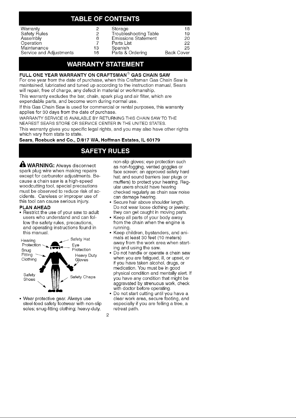
• Wear protective gear. Always use
steel-toed safety footwear with non-slip
soles; snug-fitting clothing; heavy-duty,
non-slip gloves; eye protection such
as non-fogging, vented goggles or
face screen; an approved safety hard
hat; and sound barriers (ear plugs or
mufflers) to protect your hearing. Reg-
ular users should have hearing
checked regularly as chain saw noise
can damage hearing.
• Secure hair above shoulder length.
Do not wear loose clothing or jewelry;
they can get caught in moving parts.
• Keep all parts of your body away
from the chain when the engine is
running.
• Keep children, bystanders, and ani-
mals at least 30 feet (10 meters)
away from the work area when start-
ing and using the saw.
• Do not handle or operate a chain saw
when you are fatigued, ill, or upset, or
if you have taken alcohol, drugs, or
medication. You must be in good
physical condition and mentally alert. If
you have any condition that might be
aggravated by strenuous work, check
with doctor before operating.
• Do not start cutting until you have a
clear work area, secure footing, and
especially if you are felling a tree, a
retreat path.
2
Page 3
OPERATE YOUR SAW SAFELY
• Do not operate with one hand. Seri-
ous injury to the operator, helpers, or
bystanders may result from one-
handed operation. A chain saw is in-
tended for two-handed use.
• Operate the chain saw only in a well-
ventilated outdoor area.
• Do not operate saw from a ladder or
in a tree.
• Make sure the chain will not make
contact with any object while starting
the engine. Never try to start the saw
when the guide bar is in a cut.
• Do not put pressure on the saw, es-
pecially at the end of the cut. Doing
so can cause you to lose control
when the cut is completed.
• Stop engine before setting saw down.
• Hand carry saw only when engine is
stopped. Carry with muffler away
from body; guide bar & chain project-
ing behind you; guide bar preferably
covered with a scabbard.
• Do not operate a chain saw that is
damaged, improperly adjusted, or not
completely and securely assembled.
Always replace bar, chain, hand
guard, chain brake, or other parts im-
mediately if they become damaged,
broken, or are otherwise removed.
MAINTAIN YOUR SAW IN GOOD
WORKING ORDER
• Have all chain saw service per-
formed by a qualified service dealer
except the items listed in the MAINTE-
NANCE section of this manual.
• Make certain the saw chain stops
moving when the throttle trigger is
released. For correction, refer to
CARBURETOR ADJUSTMENTS.
• Keep the handles dry, clean, and
free from oil or fuel mixture.
• Keep caps and fasteners securely
tightened.
• Nonconforming replacement compo-
nents or the removal of safety devices
may cause damage to the unit and
possible injury to the operator or by-
standers. Use only Craftsman acces-
sories and replacement parts as rec-
ommended. Never modify your saw.
• Maintain chain saw with care.
• Keep unit sharp and clean for better
and safer performance.
• Follow instructions for lubricating and
changing accessories.
• Check for damaged parts. Before fur-
ther use of the chain saw, a guard or
other part that is damaged should be
carefully checked to determine that it
will operate properly and perform its
intended function. Check for alignment
of moving parts, binding of moving
parts, breakage of parts, mounting and
any other conditions that may affect its
operation. A guard or other part that is
damaged should be properly repaired
or replaced by a Sears Service Center
unless otherwise indicated elsewhere
in the instruction manual.
• When not in use, chain saws should
be stored in a dry, high or locked-up
place out of the reach of children.
• When storing saw, use a scabbard or
carrying case.
HANDLE FUEL WITH CAUTION
• Do not smoke while handling fuel or
while operating the saw.
• Eliminate all sources of sparks or
flame in areas where fuel is mixed or
poured.
• Mix and pour fuel in an outdoor area
and use an approved, marked con-
tainer for all fuel purposes. Wipe up
all fuel spills before starting saw.
• Move at least 10 feet (3 meters) from
fueling site before starting.
• Turn the engine off and let saw cool
in a non-combustible area, not on
dry leaves, straw, paper, etc. Slowly
remove fuel cap and refuel unit.
• Store the unit and fuel in a cool, dry
well ventilated space where fuel va-
pors cannot reach sparks or open
flames from water heaters, electric
motors or switches, furnaces, etc.
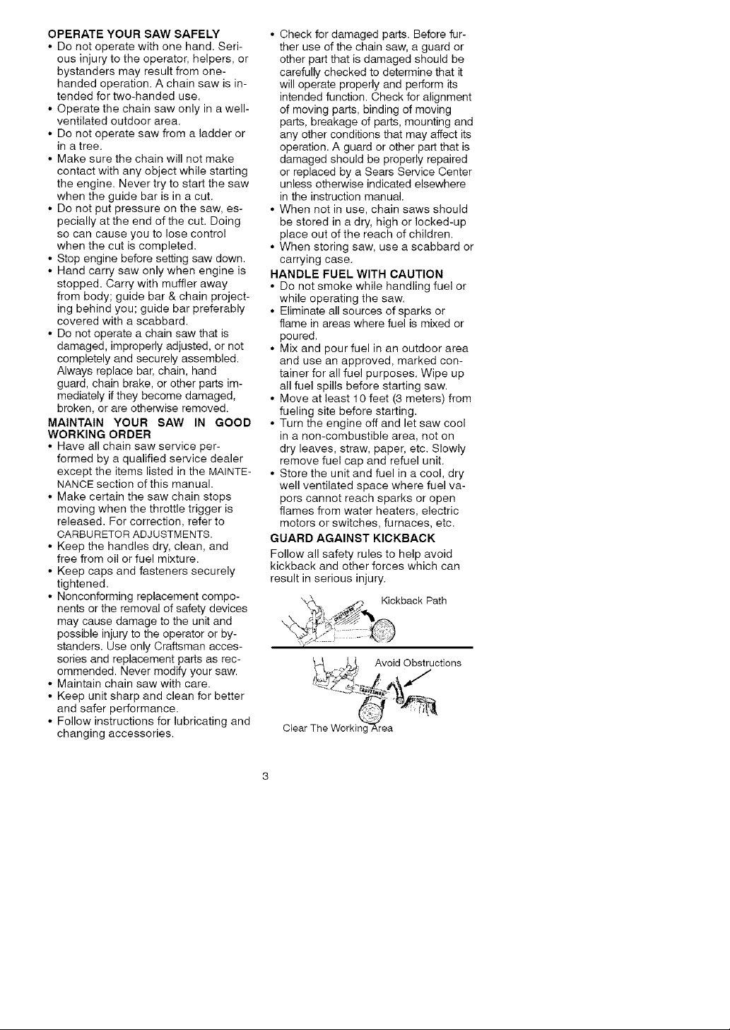
GUARD AGAINST KICKBACK
Follow all safety rules to help avoid
kickback and other forces which can
result in serious injury.
_._ _,_ Kickback Path
k_...:+j._,_ Avoid Obstructions
Clear The Worm
Page 4
A
411 WARNING: Avoid kickback which
can result in serious injury. Kickback
is the backward, upward or sudden for-
ward motion of the guide bar occurring
when the saw chain near the upper tip
of the guide bar contacts any object
such as a log or branch, or when the
wood closes in and pinches the saw
chain in the cut. Contacting a foreign
object in the wood can also result in
loss of chain saw control.
• Rotational Kickback can occur
when the moving chain contacts an
object at the upper tip of the guide
bar. This contact can cause the
chain to dig into the object, which
stops the chain for an instant. The
result is a lightning fast, reverse
reaction which kicks the guide bar up
and back toward the operator.
• Pinch-Kickback can occur when the
the wood closes in and pinches the
moving saw chain in the cut along
the top of the guide bar and the saw
chain is suddenly stopped. This sud-
den stopping of the chain results in a
reversal of the chain force used to
cut wood and causes the saw to
move in the opposite direction of the
chain rotation. The saw is driven
straight back toward the operator.
• Pull-In can occur when the moving
chain contacts a foreign object in the
wood in the cut along the bottom of
the guide bar and the saw chain is
suddenly stopped. This sudden stop-
ping pulls the saw forward and away
from the operator and could easily
cause the operator to lose control of
the saw.
REDUCE THE CHANCE OF
KICKBACK
• Recognize that kickback can happen.
With a basic understanding of kick-
back, you can reduce the element of
surprise which contributes to acci-
dents.
• Never let the moving chain contact
any object at the tip of the guide bar.
• Keep working area free from obstruc-
tions such as other trees, branches,
rocks, fences, stumps, etc. Eliminate
or avoid any obstruction that your saw
chain could hit while cutting.
• When cutting a branch, do not let the
guide bar contact another branch or
other objects around it.
• Keep saw chain sharp and properly
tensioned. A loose or dull chain can
increase the chance of kickback. Fol-
low manufacturer's chain sharpening
and maintenance instructions. Check
tension at regular intervals, but never
with engine running. Make sure chain
brake nuts are securely tightened.
• Begin and continue cutting at full
speed. If the chain is moving at a
slower speed, there is greater chance
of kickback occurring.
• Use extreme caution when reentering
a cut.
• Do not attempt cuts starting with the
tip of the bar (plunge cuts).
• Watch for shifting logs or other forces
that could close a cut and pinch or fall
into chain.
• Use the specified Reduced-Kickback
Guide Bar and Low-Kickback Chain.
Avoid Pinch-Kickback:
• Be extremely aware of situations or
obstructions that can cause material
to pinch the top of or otherwise stop
the chain.
• Do not cut more than one log at a
time.
• Do not twist saw as bar is withdrawn
from an undercut when bucking.
Avoid Pull-In:
• Always begin cutting with the engine
at full speed and the saw housing
against wood.
• Use wedges made of plastic or wood.
Never use metal to hold the cut open.
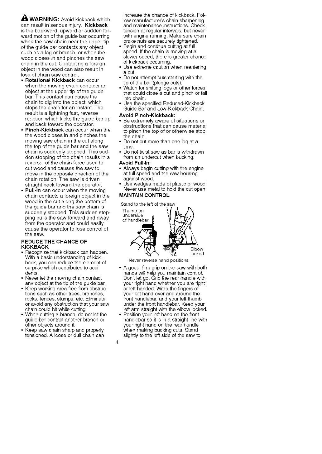
MAINTAIN CONTROL
Stand to the left of the saw
underside ,_
Thumb on \!
Elbow
locked
Never reverse hand positions
• A good, firm grip on the saw with both
hands will help you maintain control.
Don't let go. Grip the rear handle with
your right hand whether you are right
or left handed. Wrap the fingers of
your left hand over and around the
front handlebar, and your left thumb
under the front handlebar. Keep your
left arm straight with the elbow locked.
• Position your left hand on the front
handlebar so it is in a straight line with
your right hand on the rear handle
when making bucking cuts. Stand
slightly to the left side of the saw to
4
Page 5
keepyourbodyfrombeinginadirect
linewiththecuttingchain.
• Standwithyourweightevenlybal-
ancedonbothfeet.
• Donotoverreach.Youcouldbedrawn
orthrownoffbalanceandlosecontrol.
• Donotcutaboveshoulderheight.Itis
difficulttomaintaincontrolofsaw
aboveshoulderheight.
KICKBACKSAFETY FEATURES
WARNING: The following features
are included on your saw to help reduce
hazard of kickback; however, such fea-
tures will not totally eliminate this danger.
Do not rely only on safety devices. Fol-
low all safety rules to help avoid kick-
back and other forces which can result
in serious injury,
• Front Hand Guard: designed to reduce
the chance of your left hand contact-
ing the chain if your hand slips off the
front handlebar.
• Position of front and rear handlebars:
designed with distance between han-
dles and "in-line" with each other. The
spread and "in-line" position of the
hands provided by this design work
together to give balance and resis-
tance in controlling the pivot of the
saw back toward the operator if kick-
back occurs.
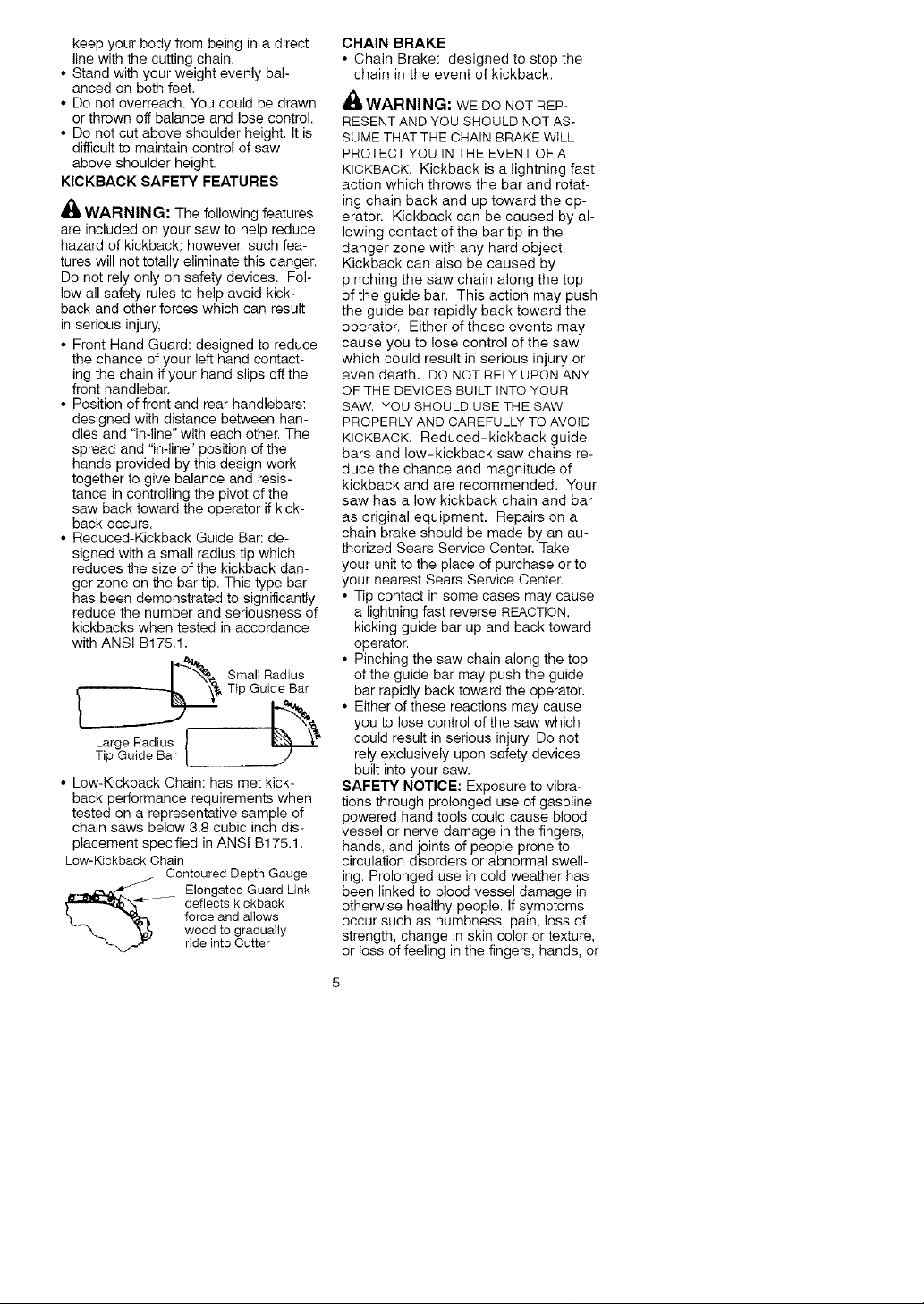
• Reduced-Kickback Guide Bar: de-
signed with a small radius tip which
reduces the size of the kickback dan-
ger zone on the bar tip. This type bar
has been demonstrated to significantly
reduce the number and seriousness of
kickbacks when tested in accordance
with ANS! B175.1.
Tip Guide Bar
____ Small Radius
Large Radius { "_
Tip Guide Bar
• Low-Kickback Chain: has met kick-
back performance requirements when
tested on a representative sample of
chain saws below 3.8 cubic inch dis-
placement specified in ANSI B175.1.
Low-Kickback Chain
__ longated Guard Link
Contoured Depth Gauge
deflects kickback
force and allows
wood to gradually
ride into Cutter
CHAIN BRAKE
• Chain Brake: designed to stop the
chain in the event of kickback.
AI_, WARNING: WE DO NOT REP-
RESENT AND YOU SHOULD NOT AS-
SUME THAT THE CHAIN BRAKE WiLL
PROTECT YOU IN THE EVENT OF A
KICKBACK. Kickback is a lightning fast
action which throws the bar and rotat-
ing chain back and up toward the op-
erator. Kickback can be caused by al-
lowing contact of the bar tip in the
danger zone with any hard object.
Kickback can also be caused by
pinching the saw chain along the top
of the guide bar. This action may push
the guide bar rapidly back toward the
operator. Either of these events may
cause you to lose control of the saw
which could result in serious injury or
even death. DO NOT RELY UPON ANY
OF THE DEVICES BUILT INTO YOUR
SAW. YOU SHOULD USE THE SAW
PROPERLY AND CAREFULLY TO AVOID
KICKBACK. Reduced-kickback guide
bars and low-kickback saw chains re-
duce the chance and magnitude of
kickback and are recommended. Your
saw has a low kickback chain and bar
as original equipment. Repairs on a
chain brake should be made by an au-
thorized Sears Service Center. Take
your unit to the place of purchase orto
your nearest Sears Service Center.
• Tip contact in some cases may cause
a lightning fast reverse REACTION,
kicking guide bar up and back toward
operator.
• Pinching the saw chain along the top
of the guide bar may push the guide
bar rapidly back toward the operator.
• Either of these reactions may cause
you to lose control of the saw which
could result in serious injury. Do not
rely exclusively upon safety devices
built into your saw.
SAFETY NOTICE: Exposure to vibra-
tions through prolonged use of gasoline
powered hand tools could cause blood
vessel or nerve damage in the fingers,
hands, and joints of people prone to
circulation disorders or abnormal swell-
ing. Prolonged use in cold weather has
been linked to blood vessel damage in
otherwise healthy people. If symptoms
occur such as numbness, pain, loss of
strength, change in skin color or texture,
or loss of feeling in the fingers, hands, or
Page 6
joints,discontinuetheuseofthistool
andseekmedicalattention.Ananti-vi-
brationsystemdoesnotguaranteethe
avoidanceoftheseproblems.Users
whooperatepowertoolsonacontinual
andregularbasismustcloselymonitor
theirphysicalconditionandthecondition
ofthistool.
CHAIN BRAKE: If this saw is to be
used for commercial logging, a chain
brake is required and shall not be re-
moved or otherwise disabled to comply
with Federal OSHA Regulations for
Commercial Logging.
SPARK ARRESTING SCREEN: Your
saw is equipped with a temperature lim-
iting muffler and spark arresting screen
which meets the requirements of Califor-
nia Codes 4442 and 4443. All U.S. for-
est land and the states of California, Ida-
ho, Maine, Minnesota, New Jersey,
Oregon, and Washington require by law
that many internal combustion engines
be equipped with a spark arresting
screen. If you operate a chain saw in a
state or locale where such regulations
exist, you are legally responsible for
maintaining the operating condition of
these parts. Failure to do so is a viola-
tion of the law. Refer to Customer Re-
sponsibilities chart in the MAINTENANCE
section.
STANDARDS: This chain saw is listed
by Underwriters Laboratories, Inc. in ac-
cordance with American National Stan-
dards for Gasoline-Powered Chain
Saws Safety Requirements (ANSI
B175.1-2000).
A
WARNING: Before using chain
saw, ensure all fasteners are secure.
CARTON CONTENTS
Check carton contents against the fol-
lowing list.
Model 358.350370
• Chain Saw (fully assembled)
• Bar tool
• 2-cycle engine oil
• Carrying case
• Extra chain
• Log carrier
Examine parts for damage. Do not use
damaged parts.
If you need assistance or find that parts
are missing or damaged, please call
1-800-235-5878.
NOTE: It is normal to hear the fuel filter
rattle in an empty fuel tank.
Your unit has been factory tested and
the carburetor precisely adjusted. As a
result you may smell gasoline or find a
drop of oil/fuel residue on the muffler
when you unpack the unit.
ASSEMBLY
Your saw is fully assembled; no
assembly is necessary.
Page 7
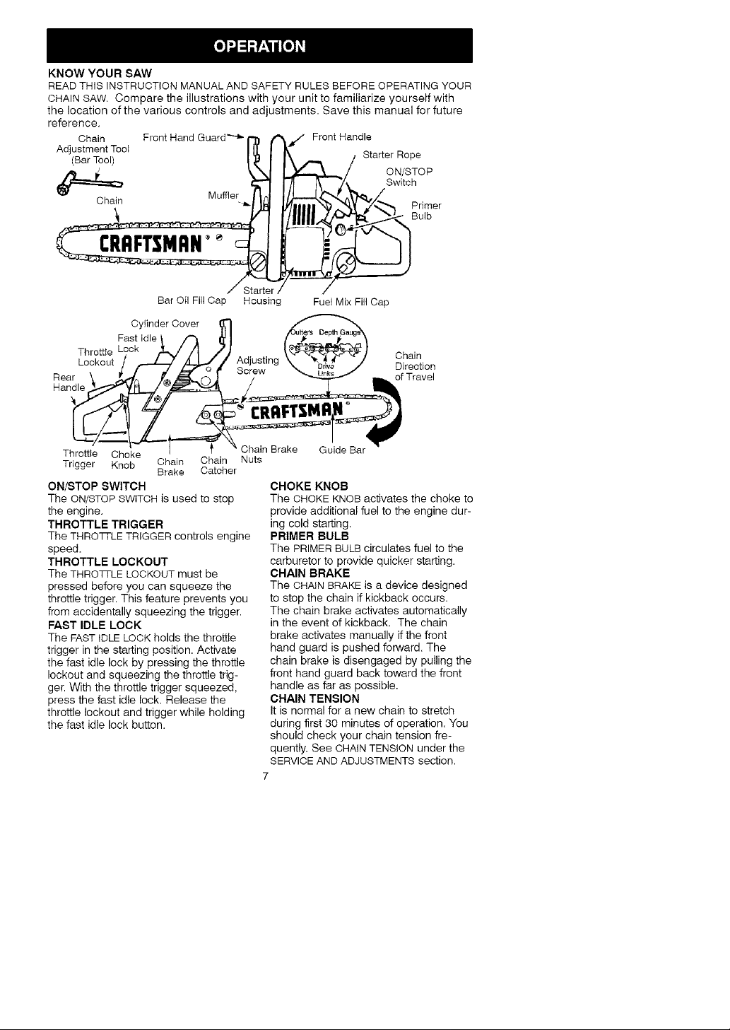
KNOWYOURSAW
READTHISINSTRUCTIONMANUALANDSAFETYRULESBEFOREOPERATINGYOUR
CHAINSAW.Comparetheillustrationswithyourunittofamiliarizeyourselfwith
thelocationofthevariouscontrolsandadjustments.Savethismanualforfuture
reference.
Chain FrontHandGuard''-_r']] /_ _/.. Front Handle
Adjustment Tool I II I It- Starter Roe
/BarToo / I: 1 I\.", f P
/9 _ k_l _/ ON/STOP
'_ -.. Muffler flJ ItL_.JP-,.P.t'_, /
Cha,n "_'IN _/| |I | |'N'_ _----'4"__7_--_"'_ Prh:qer
Bar Oil Fill Cap Housing Fuel Mix Fill Cap
Cylinder Cover
Fast Idle
Throttte Chain
Lockout Adjusting
_ F/_ R _/_ Switch
Screw Direction
of Travel
Throttle Choke
Trigger Knob Chain Chain Nuts
ON/STOP SWITCH
The ON/STOP SWITCH is used to stop
the engine.
THROTTLE TRIGGER
The THRO]q-LE TRIGGER controls engine
speed.
THROTTLE LOCKOUT
The THRO3-I-LE LOCKOUT must be
pressed before you can squeeze the
throttle trigger. This feature prevents you
from accidentally squeezing the trigger.
FAST IDLE LOCK
The FAST IDLE LOCK holds the throttle
trigger in the starting position. Activate
the fast idle lock by pressing the throttle
lockout and squeezing the throttle trig-
ger. With the throttle trigger squeezed,
press the fast idle lock. Release the
throttle lockout and trigger while holding
the fast idle lock button.
Brake Catcher
_' Chain Brake Guide Bar
CHOKE KNOB
The CHOKE KNOB activates the choke to
provide additional fuel to the engine dur-
ing cold starting.
PRIMER BULB
Tile PRIMER BULB circulates fuel to the
carburetor to provide quicker starting.
CHAIN BRAKE
Tile CHAIN BRAKE is a device designed
to stop the chain if kickback occurs.
The chain brake activates automatically
in the event of kickback. The chain
brake activates manually if the front
hand guard is pushed forward. The
chain brake is disengaged by pulling the
front hand guard back toward the front
handle as far as possible.
CHAIN TENSION
It is normal for a new chain to stretch
during first 30 minutes of operation. You
should check your chain tension fre-
quently. See CHAINTENSION under the
SERVICEAND ADJUSTMENTS section.
7
Page 8

z_
_ WARNING:Mufflerisveryhot
duringandafteruse.Donottouchthe
mufflerorallowcombustiblematerial
suchasdrygrassorfueltodoso.
BEFORESTARTING ENGINE
,_L WARNING: Be sure to read the
fuel handling information in the safety
rules section of this manual before you
begin. If you do not understand the
fuel handling information do not at-
tempt to fuel your unit. Seek help from
someone that does understand the in-
formation or call the customer assis-
tance help line at 1-800-235-5878.
GUIDE BAR AND CHAIN OIL
The bar and chain require lubrication.
The chain oiler provides continuous
lubrication to the chain and guide bar.
Be sure to fill the bar oil tank when you
fill the fuel tank (Capacity = 6.8 ft. oz.).
Lack of oil will quickly ruin the bar and
chain. Too little oil will cause overheat-
ing shown by smoke coming from the
chain and/or discoloration of the bar.
For maximum guide bar and chain life,
we recommend you use Craftsman
chain saw bar oil. If Craftsman bar oil
is not available, you may use a good
grade SAE 30 oil until you are able to
obtain Craftsman brand. The oil output
is automatically metered during opera-
tion. Your saw will use approximately
one tank of bar oil for every tank of fuel
mix. Always fill the bar oil tank when
you fill the fuel tank.
FUELING ENGINE
,_L WARNING: Remove fuel cap
slowly when refueling.
This engine is certified to operate on
unleaded gasoline. Before operation,
gasoline must be mixed with a good
quality 2-cycle air-cooled engine oil.
We recommend Craftsman brand oil.
Mix gasoline and oil at a ratio of 40:1.
A 40:1 ratio is obtained by mixing 3.2
ounces of oil with 1 gallon of unleaded
gasoline. Included with this saw is a
3.2 ounce container of Craftsman
brand oil. Pour the entire contents of
this container into 1 gallon of gasoline
to achieve the proper fuel mixture.
DO NOT USE automotive oil or boat oil.
These oils will cause engine damage.
When mixing fuel follow the instruc-
tions printed on the oil container.
Once oil is added to the gasoline,
shake container momentarily to assure
that the fuel is thoroughly mixed. Al-
ways read and follow the safety rules
relating to fuel before fueling your unit.
IMPORTANT
Experience indicates that alcohol
blended fuels (called gasohol or using
ethanol or methanol) can attract mois-
ture which leads to separation and
formation of acids during storage. Acidic
gas can damage the fuel system of an
engine while in storage. To avoid engine
problems, the fuel system should be
emptied before storage for 30 days or
longer. Drain the gas tank, start the en-
gine and let it run until the fuel lines and
carburetor are empty. Use fresh fuel
next season. See STORAGE instructions
for additional information.
Never use engine or carburetor clean-
er products in the fuel tank or perma-
nent damage may occur.
See the STORAGE section for addition-
al information.
CHAIN BRAKE
Ensure chain brake is disengaged by
pulling the front hand guard back to-
ward the front handle as far as pos-
sible. The chain brake must be disen-
gaged before cutting with the saw.
,_,WARNING: The chain must not
move when the engine runs at idle
speed. If the chain moves at idle
speed, refer to CARBURETOR ADJUST-
MENT within this manual. Avoid con-
tact with the muffler. A hot muffler can
cause serious burns.
STOPPING YOUR ENGINE
• Move ON/STOP switch to the STOP
position.
STARTING POSITION
• To start the engine, hold the saw
firmly on the ground as illustrated.
Make sure the chain is free to turn
without contacting any object.
Starter Rope Handle
!
Right'Foot Through Rear Handle
8
Page 9

IMPORTANT POINTS TO REMEMBER
When pulling the starter rope, do not
use the full extent of the rope as this
can cause the rope to break. Do not
let starter rope snap back. Hold the
handle and let the rope rewind slowly.
NOTE: DO NOT attempt to cut material
with the fast idle lock button in the
locked position.
STARTING A COLD ENGINE (or a
warm engine after running out of
fuel)
1. Move ON/STOP switch to ON posi-
tion.
2. Pull choke knob out to the full ex-
tent.
3. Slowly press the primer bulb 6
times.
Primer Bulb
Switch
ON/STOP __
Choke _[-_-' !
Knob LJ _t__,
4. Squeeze and hold throttle trigger.
With thumb press fast idle lock
down; then release throttle trigger.
5. Sharply pull the starter rope handle
5 times with your right hand. Then,
proceed to the next step.
NOTE: If the engine sounds as if it is
trying to start before the 5th pull, stop
pulling and immediately proceed to the
next step.
6. Fully push in choke knob (to the
OFF position); pull the starter rope
until the engine starts.
7. Allow the engine to run for approxi-
mately 5 seconds. Then, squeeze
and release the throttle trigger to al-
low engine to return to idle speed.
STARTING A WARM ENGINE
1. Fully push in choke knob (to the
OFF position).
2. Move ON/STOP switch to ON posi-
tion.
3. Slowly press primer bulb 6 times.
4. Squeeze and hold throttle trigger.
With thumb press fast idle lock
down; then release throttle trigger.
5. Sharply pull starter rope with your
right hand until the engine starts.
6. Squeeze and release the throttle
trigger to return engine to idle
speed.
off Full
DIFFICULT STARTING (or starting a
flooded engine)
The engine may be flooded if it has not
started after 10 pulls.
Flooded engines can be cleared of ex-
cess fuel by following the warm engine
starting procedure listed above. Ensure
the ON/STOP switch is inthe ON position.
Starting could require many pulls de-
pending on how badly unit is flooded.
If engine still fails to start, refer to the
TROUBLESHOOTING TABLE or call
1-800-235-5878.
CHAIN BRAKE
,_ WARNING: If tile brake band is
worn too thin it may break when the
chain brake is triggered. With a broken
brake band, the chain brake will not stop
the chain. The chain brake must be re-
placed if any part is worn to less than
1/32" thick. Repairs on a chain brake
should be made by your Sears Service
Center. Take your unit to the place of
purchase or to the nearest Sears Ser-
vice Center.
• This saw is equipped with a chain
brake. The brake is designed to stop
the chain if kickback occurs.
• The inertia-activated chain brake is
activated if the front hand guard is
pushed forward, either manually (by
hand) or automatically (by sudden
movement).
• If the brake is already activated, it is
disengaged by pulling the front hand
guard back toward the front handle
as far as possible.
• When cutting with the saw, the chain
brake must be disengaged.
Disengaged
: Engaged
Braking function control
CAUTION: The chain brake must be
checked several times daily. The engine
must be running when performing this
procedure. This is the only instance
when the saw should be placed on the
ground with the engine running.
Place the saw on firm ground. Grip the
rear handle with your right hand and
the front handle with your left hand.
Apply full throttle by fully depressing
the throttle trigger. Activate the chain
brake by turning your left wrist against
9
Page 10

thehandguardwithoutreleasingyour
griparoundthefronthandle.Thechain
shouldstopimmediately.
Inertiaactivating function control
_.WARNING: When performing the
following procedure, the engine must
be turned off.
Grip the rear handle with your right hand
and the front handle with your left hand.
Hold the chain saw approximately 14"
(35 cm) above a stump or other wood-
en surface. Release your grip on the
front handle and let the tip of the guide
bar fall forward and contact the stump.
When the tip of the bar hits the stump,
the brake should activate.
OPERATING TIPS
• Check chain tension before first use
and after 1 minute of operation. See
CHAIN TENSION in the MAINTENANCE
section.
• Cut wood only. Do not cut metal,
plastics, masonry, non-wood building
materials, etc.
• Stop the saw if the chain strikes a
foreign object. Inspect the saw and
repair parts as necessary.
• Keep the chain out of dirt and sand.
Even a small amount of dirt will
quickly dull a chain and increase the
possibility of kickback.
• Practice cutting a few small logs us-
ing the following steps. This will help
you get the "feel" of using your saw
before you begin a major sawing op-
eration.
• Squeeze the throttle trigger and al-
low the engine to reach full speed
before cutting.
• Begin cutting with the saw frame
against the log.
• Keep the engine at full speed the
entire time you are cutting.
• Allow the chain to cut for you. Exert
only light downward pressure.
• Release the throttle trigger as soon
as the cut is completed, allowing
the engine to idle. If you run the
saw at full throttle without a cutting
load, unnecessary wear can occur.
• To avoid losing control when cut is
complete, do not put pressure on
saw at end of cut.
• Stop engine before setting saw
down.
TREE FELLING TECHNIQUES
'_ WARNING: Check for broken or
dead branches which can fall while cut-
ting causing serious injury. Do not cut
near buildings or electrical wires if you
do not know the direction of tree fall, nor
cut at night since you will not be able to
see well, nor during bad weather such
as rain, snow, or strong winds, etc.
• Carefully plan your sawing operation
in advance.
• Clear the work area. You need a
clear area all around the tree so you
can have secure footing.
• The chain saw operator should keep
on the uphill side of the terrain as the
tree is likely to roll or slide downhill
after it is felled.
• Study the natural conditions that can
cause the tree to fall in a particular
direction. These conditions include:
• The wind direction and speed.
• The lean of the tree. The lean of a
tree might not be apparent due to
uneven or sloping terrain. Use a
plumb or level to determine the di-
rection of tree lean.
• Weight and branches on one side.
• Surrounding trees and obstacles.
• Look for decay and rot. If the trunk is
rotted, it can snap and fall toward the
operator.
• Make sure there is enough room for
the tree to fall. Maintain a distance of
2-1/2 tree lengths from the nearest
person or other objects. Engine
noise can drown out a warning call.
• Remove dirt, stones, loose bark,
nails, staples, and wire from the tree
where cuts are to be made.
'f"e Plan a clear retreat path
.... _L .,_-'_'" Direction of fall
45_ /,,..
y/e.#"
FELLING LARGE TREES
(6 inches in diameter or larger)
The notch method is used to fell large
trees. A notch is cut on the side of the
tree in the desired direction of fall. After
a felling cut is made on the opposite
side of tree, the tree will tend to fall in
the direction of the notch.
10
Page 11

NOTE:Iftreehaslargebuttressroots,
removethembeforemakingthenotch.
Ifusingsawtoremovebuttressroots,
keepsawchainfromcontacting
groundtopreventdullingofthechain.
NOTCHCUTAND FELLING TREE
• Make notch cut by cutting the top of
the notch first. Cut through 1/3 of the
diameter of the tree. Next complete
the notch by cutting the bottom. See
illustration. Once the notch is cut, re-
move the wedge of wood from tree.
Firstcut ) =,. j
Second cut_ j \ e
• After removing the wood from the
notch, make the felling cut on the op-
posite side of the notch. This is done
by making a cut about two inches
higher than the center of the notch.
This will leave enough uncut wood
between the felling cut and the notch
to form a hinge. This hinge will help
prevent the tree from falling in the
wrong direction.
Closing
of notch
NOTE: Before felling cut is complete,
use wedges to open the cut when
necessary to control the direction of
fall. To avoid kickback and chain
damage, use wood or plastic wedges,
but never steel or iron wedges.
• Be alert to signs that the tree is ready
to fall: cracking sounds, widening of
the felling cut, or movement in the up-
per branches.
• As tree starts to fall, stop saw, put it
down, and get away quickly on your
planned retreat path.
• DO NOT use your saw to cut down a
partially fallen tree. Be extremely
cautious with partially fallen trees
that may be poorly supported. When
a tree doesn't fall completely, set the
Felling cut here
Hinge holds tree on
stump and helps
control fall
Opening of
felling cut
saw aside and pull down the tree
with a cable winch, block and tackle,
or tractor.
CUTTING A FALLEN TREE
(BUCKING)
Bucking is tile term used for cutting a
fallen tree to the desired log size.
,_& WARNING: Do not stand on the
log being cut. Any portion can roll
causing loss of footing and control. Do
not stand downhill of the log being cut.
IMPORTANT POINTS
• Cut only one log at a time.
• Cut shattered wood very carefully;
sharp pieces of wood could be flung
toward operator.
• Use a sawhorse to cut small logs.
Never allow another person to hold
the log while cutting and never hold
the log with your leg or foot.
• Do not cut in an area where logs,
limbs, and roots are tangled. Drag
logs into a clear area before cutting
them by pulling out exposed and
cleared logs first.
BUCKING TECHNIQUES
_, WARNING: If saw becomes
pinched or hung in a log, don't try to
force it out. You can lose control of the
saw resulting in injury and/or damage
to the saw. Stop the saw, drive a
wedge of plastic or wood into the cut
until the saw can be removed easily.
Restart saw and carefully reenter the
cut. Do not use a metal wedge. Do not
attempt to restart your saw when it is
pinched or hung in a log.
Use a wedge to remove pinched saw
Turn saw OFF and use a plastic or
wooden wedge to force cut open.
Overcutting begins on the top side of
the log with the bottom of the saw
against the log. When overcutting use
light downward pressure.
x(XOvercutting ,i __%_
_':;Z-'_ Undercuttin_;
Undercutting involves cutting on the
underside of the log with top of saw
against the log. When undercutting
use light upward pressure. Hold saw
11
Page 12

firmlyandmaintaincontrol.Thesaw
willtendtopushbacktowardyou.
WARNING:Neverturnsawup-
sidedowntoundercut.Thesawcan-
notbecontrolledinthisposition.
Alwaysmakeyourfirstcutonthecom-
pressionsideofthelog.Thecompres-
sionsideofthelogiswherethepres-
sureofthelog'sweightis
concentrated.
Firstcutoncompressionsideoflog
Using a support stand
/ __m 2nd Cut
2nd Cut
Secondcut
First cut on compression side of log
BUCKING WITHOUT A SUPPORT
• Overcut through 1/3 of the diameter
of the log.
• Roll the log over and finish with a
second overcut.
• Watch for logs with a compression
side to prevent the saw from pinch-
ing. See illustrations above for cut-
ting logs with a compression side.
BUCKING USING A LOG OR
SUPPORT STAND
• Remember your first cut is always on
the compression side of the log. (Re-
fer to the illustrations below for your
first and second cut).
• Your first cut should extend 1/3 of the
diameter of the log.
• Finish with your second cut.
Using a log for support
2ndCut
LIMBING AND PRUNING
WARNING: Be alert for and guard
against kickback. Do not allow the mov-
ing chain to contact any other branches
or objects at the nose of the guide bar
when limbing or pruning. Allowing such
contact can result in serious injury.
WARNING: Never climb into a
tree to _imb or prune. Do not stand on
ladders, platforms, a log, or in any po-
sition which can cause you to lose
your balance or control of the saw.
IMPORTANT POINTS
• Watch out for springpoles.
Springpoles are small size limbs
which can whip toward you, or pull
you off balance. Use extreme cau-
tion when cutting small size limbs.
• Be alert for springback from any
branches that are bent or under
pressure. Avoid being struck by the
branch or the saw when the tension
in the wood fibers is released.
• Frequently clear branches out of the
way to avoid tripping over them.
LIMBING
• Limb a tree only after it is cut down.
• Leave the larger limbs underneath
the felled tree to support the tree as
you work.
• Start at the base of the felled tree
and work toward the top, cutting
branches and limbs. Remove small
limbs with one cut.
• Keep the tree between you and the
chain.
• Remove larger branches with the
cutting techniques described in
BUCKING WITHOUT A SUPPORT.
12
Page 13

• Alwaysuseanovercuttocutsmall
andfreelyhanginglimbs.Undercut-
tingcouldcauselimbstofalland
pinchthesaw.
PRUNING
_WARNING: Limit pruning to limbs
shoulder height or below. Do not cut if
branches are higher than your shoul-
der. Get a professional to do the job.
• Make your first cut 1/3 of the way
through the bottom of the limb. This
cut will make the limb sag so that it
falls easily on the second cut.
• Next make the second cut an over-
cut all the way through the limb.
• Finish the pruning operation by using
an overcut so that the stump of the
limb protrudes 1 to 2 inches from the
trunk of the tree.
/_ Third cut 1to 2inches from trunk
of tree
,_ WARNING:
except for carburetor adjustments.
CUSTOMER RESPONSIBILITIES
Fill in dates as you complete
regular service
Check for damaged/worn parts
Check for loose fasteners/parts
Check chain tension
Check chain sharpness
Check guide bar
Check fuel mixture level
Check guide bar and chain oil
Lubricate bar sprocket hole
Inspect and clean unit & decals
Check chain brake
Clean guide bar groove
Clean air filter
Clean/inspect muffler and spark
arresting screen
Replace spark plug and fuel filter
GENERAL RECOMMENDATIONS
The warranty on this unit does not cov-
er items that have been subjected to
operator abuse or negligence. To re-
ceive full value from the warranty, the
operator must maintain unit as instruct-
ed in this manual. Various adjustments
will need to be made periodically to
properly maintain your unit.
• Once a year, replace the spark plug,
air filter element, and check guide bar
Disconnect the spark plug before performing maintenance
Before After Ever Every \, ,_ Service
Use Use 5 hrs. 25 hrs. Teany Dates
v,"
v,"
v"
and chain for wear. A new spark plug
and air filter element assures proper
air-fuel mixture and helps your engine
run better and last longer.
CHECK FOR DAMAGED OR
WORN PARTS
Contact Sears Service Center for re-
placement of damaged or worn parts.
NOTE: It is normal for a small amount
of oil to appear under the saw after en-
13
Page 14

ginestops.Donotconfusethiswitha
leakingoiltank.
• ON/STOPSwitch- EnsureON/STOP
switchfunctionsproperlybymoving
theswitchtotheSTOPposition.
Makesureenginestops;thenrestart
engineandcontinue.
• FuelTank- Donotusesawiffuel
tankshowssignsofdamageor
leaks.
• OilTank- Donotusesawifoiltank
showssignsofdamageorleaks.
CHECKFORLOOSE
FASTENERS AND PARTS
• Chain Brake Nuts
• Chain
• Muffler
• Cylinder Shield
• Air Filter
• Handle Screws
• Vibration Mounts
• Starter Housing
• Front Hand Guard
CHECK CHAIN TENSION
_i WARNING: Wear protective
gloves when handling chain. The
chain is sharp and can cut you even
when it is not moving.
Chain tension is very important.
Chains stretch during use. This is es-
pecially true during the first few times
you use your saw. Always check
chain tension each time you use and
refuel your saw.
1. Use the screwdriver end of the
chain adjustment tool (bar tool) to
move chain around guide bar to
ensure kinks do not exist. The
chain should rotate freely.
f-_ zZ_o/ii_k Guide
•-_-_ I_--_"_.._Bar
Chain Brake Adjusting Tool
Nuts Screw (Bar Tool)
2. Loosen chain brake nuts until they
are finger tight against the chain
brake.
3. Turn adjusting screw clockwise un-
til chain solidly contacts bottom of
guide bar rail.
4. Using bar tool, roll chain around
guide bar to ensure all links are in
bar groove.
5. Lift up tip of guide bar to check for
sag. Release tip of guide bar, then
turn adjusting screw until sag does
not exist.
6. While lifting tip of guide bar, tighten
chain brake nuts securely with the
bar tool.
Chain Brake
7. Use the screwdriver end of the bar
tool to move chain around guide bar.
8. If chain does not rotate, it is too
tight. Slightly loosen chain brake
nuts and loosen chain by turning
the adjusting screw counterclock-
wise. Retighten chain brake nuts.
9. If chain is too loose, it will sag be-
low the guide bar. DO NOT operate
the saw if the chain is loose.
_i, WARNING: If the saw is operated
with a loose chain, the chain could
jump offthe guide bar and result in se-
rious injury.
CHECK CHAIN SHARPNESS
A sharp chain makes wood chips. A
dull chain makes a sawdust powder
and cuts slowly. See CHAIN SHARP-
ENING in the SERVICE AND ADJUST-
MENTS section.
CHECK GUIDE BAR
Conditions which require guide bar
maintenance:
• Saw cuts to one side or at an angle.
• Saw has to be forced through the cut.
• Inadequate supply of oil to bar/chain.
Check the condition of guide bar each
time chain is sharpened. A worn guide
bar will damage the chain and make
cutting difficult.
After each use, ensure ON/STOP
switch is in the STOP position, then
clean all sawdust from the guide bar
and sprocket hole.
14
Page 15

Tomaintainguidebar:
• MoveON/STOPswitchtoSTOP.
• Loosenandremovechainbrake
nutsandchainbrake.Removebar
andchainfromsaw.
• Cleantheoilholesandbargroove
aftereach5hoursofoperation.
RemoveSawdustFrom_ _
Guide Bar Groov_
_ Sprocket Hole
Oil Holes o
• Add lubricant to sprocket hole after
each use.
• Burring of guide bar rails is a normal
process of rail wear. Remove these
burrs with a flat file.
• When rail top is uneven, use a flat
file to restore square edges and
sides.
_1"__r7_ File Rail Edges_r] r}
Worn Groove Correct Groove
Replace guide bar when the groove is
worn, the guide bar is bent or cracked,
or when excess heating or burring of the
rails occurs. If replacement is necessary,
use only the guide bar specified for your
saw in the repair parts list or on the de-
cal located on the chain saw.
CHECK FUEL MIXTURE LEVEL
• See FUELING ENGINE under the OP-
ERATION section.
LUBRICATION
ha;Sprocket B_lrOilp
• See GUIDE BAR AND CHAIN OIL un-
der the OPERATION section.
• Lubricate bar sprocket hole after
each use.
INSPECT AND CLEAN UNIT AND
DECALS
• After each use, inspect complete unit
for loose or damaged parts. Clean
the unit and decals using a damp
cloth with a mild detergent.
• Wipe off unit with a clean dry cloth.
CHECK CHAIN BRAKE
• See CHAIN BRAKE in the OPERATION
section.
and Sides I U I
square [ ]
CLEAN AIR FILTER
A dirty air filter decreases the life and
performance of the engine and in-
creases fuel consumption and harmful
emissions. Always clean your air filter
after 15 tanks of fuel or 5 hours of op-
eration, whichever comes first. Clean
more frequently in dusty conditions. A
used air filter can never be completely
cleaned. It is advisable to replace your
air filter with a new one after every 50
hours of operation, or annually, which-
ever comes first. To clean filter:
1. Loosen 3 screws on cylinder cover.
2. Remove cylinder cover.
3. Remove air filter.
4. Clean the air filter using hot soapy
water. Rinse with clean cool water.
Air dry completely before reinstalling.
5. Lightly oil air filter before installing to
improve the efficiency of air filter.
Use 2-cycle engine oil or motor oil
(SAE 30). Squeeze excess oil from
filter.
6. Reinstall air filter.
7. Reinstall cylinder cover and 3
screws. Tighten securely.
- _ Cylinder Cover
Air Filter_
P-.€
-,_' Screws
J X
/'_ ylinder
_ver
INSPECT MUFFLER AND SPARKAR-
RESTING SCREEN
As the unit is used, carbon deposits
build up on the muffler and spark ar-
resting screen, and must be removed
to avoid creating a fire hazard or af-
fecting engine performance.
Replace the spark arresting screen if
breaks occur.
Muffler iffuser
Spark
Arresting
_F"_/_-"d_---- _ /_ I/ Screen
\//\1 I / off,er
-'k Cover
Body -- _ Muffler
15
Cover
Page 16

CLEANINGTHE SPARK
ARRESTING SCREEN
Cleaning is required every 25 hours of
operation or annually, whichever
comes first.
1. Loosen and remove the 2 muffler
cover screws.
2. Remove the muffler cover (cover
snaps off muffler body).
3. Remove muffler diffuser and spark
arresting screen assembly. Notice
the orientation of these parts for
reassembling.
4. Clean the spark arresting screen
with a wire brush. Replace screen
if breaks are found.
5. Replace any broken or cracked
muffler parts.
6. Reinstall diffuser and spark arrest-
ing screen assembly with round
holes facing up.
7. Reinstall muffler cover and 2
screws. Tighten securely.
REPLACE SPARK PLUG
The spark plug should be replaced
each year to ensure the engine starts
easier and runs better. Ignition timing
is fixed and nonadjustable.
1. Loosen 3 screws on cylinder
cover.
2. Remove the cylinder cover.
3. Pull offthe spark plug boot.
4. Remove spark plug from cylinder
and discard.
5. Replace with Champion CJ-7Y
spark plug and tighten securely
with a 3/4 inch socket wrench.
Spark plug gap should be 0=025 in.
6. Reinstall the spark plug boot.
7. Reinstall the cylinder cover and 3
screws. Tighten securely.
'linder
Spark
Plug Boot
Spark
Plug
Cover
REPLACE FUEL FILTER
To replace fuel filter, drain your unit by
running it dry of fuel. Remove fuel cap
and its connected retainer from tank.
Pull filter from tank and remove from
line= Replace and reassemble=
,it
WARNING: Disconnect the spark
plug before performing maintenance,
service, or adjustments except for car-
buretor adjustments.
CHAIN SHARPENING
Chain sharpening requires special
tools. You can purchase sharpening
tools at Sears or go to a professional
chain sharpener.
CHAIN REPLACEMENT
WARNING: Wear protective
gloves when handling chain. The
chain is sharp and can cut you even
when it is not moving.
It is normal for a new chain to stretch
during the first 15 minutes of operation.
You should recheck your chain tension
frequently and adjust the chain tension
as required. See CHAIN TENSION sec-
tion.
Replace the old chain when it be-
comes worn or damaged. Use only
the Low-Kickback replacement chain
specified in the repair parts list. The
correct replacement bar and chain is
also specified on a decal located on
the chain saw.
See your Sears Service Center to re-
place and sharpen individual cutters
on your chain.
TO REPLACE CHAIN:
1. Move ON/STOP switch to tile STOP
position.
2. Remove chain brake nuts.
3. Remove chain brake.
Chain
Brake
16
Page 17

4. Turnadjustingscrewonbarcoun-
terclockwisetomovethetension-
ingrackasfarasitwillgotoward
thefrontofthebar.
TensioningRL_ac_
5. Slideguidebarbehindclutchdrum
untilguidebarstopsagainstclutch
drumsprocket.
6. Removetheoldchain.
7. Carefullyremovenewchainfrom
package.Holdchainwiththedrive
linksasshown.
Cutters DepthGauge
DriveLinks
8. Placechainoverandbehind
clutch,fittingthedrivelinksinthe
clutchdrumsprocket.
9. Fitbottomofdrivelinksbetween
theteethinthesprocketinthe
noseoftheguidebar.
10.Fitchaindrivelinksintobargroove.
11.Pullguidebarforwarduntilchainis
snuginguidebargroove.Ensure
alldrivelinksareinthebargroove.
12.Installchainbrake.
13.Installchainbrakenutsandfinger
tightenonly.Donottightenanyfur-
theratthispoint.Proceedto
CHAINADJUSTMENT.
CHAIN ADJUSTMENT
See CHAIN TENSION in MAINTENANCE
section.
CARBURETOR ADJUSTMENT
_IWARNING: The chain will be
moving during most of this procedure.
Wear your protective equipment and ob-
serve all safety precautions. During the
low speed mixture adjustment recheck
idle speed after each turn of the screw.
The chain must not move at idle speed.
Carburetor adjustment is critical and if
done improperly can permanently dam-
age the engine as well as the carbure-
tor. If you require further assistance or
are unsure about performing this proce-
dure, call our customer assistance help
line at 1-800-235-5878.
Old fuel, a dirty air filter, dirty fuel filter, or
flooding may give the impression of an
improperly adjusted carburetor. Check
these conditions before adjusting the
carburetor.
The carburetor has been carefully set at
the factory. Adjustments may be neces-
sary if you notice any of the following
conditions:
• Chain moves at idle. See IDLE
SPEED-T under adjusting procedure.
• Saw will not idle. See IDLE SPEED-T
and LOW SPEED MIXTURE-L under
adjusting procedure.
• Engine dies or hesitates when it
should accelerate. See ACCELERA-
TION CHECK under adjusting
procedure.
• Loss of cutting power. See HIGH
SPEED MIXTURE - H under adjusting
procedure.
There are three adjustment screws on
the carburetor. They are labeled H, L,
and T. They are located in the area just
above the primer bulb.
ADJUSTING PROCEDURE
CAUTION: Do not force plastic limiter
caps on screws beyond the built-in
stops or damage will occur.
Initial Settings
1. Turn both mixture screws (L and H)
counterclockwise until they stop.
2. Turn the idle speed screw (T)
clockwise until it stops. Then turn it
counterclockwise 4 and 1/2 turns.
3. Start engine and let it run for 3 min-
utes, then proceed to adjust
screws according to the instruc-
tions below. If engine performance
at initial settings is acceptable, no
further adjustments are necessary.
If engine does not start, refer to the
TROUBLESHOOTING TABLE.
If still unable to remedy situation,
call 1-800-235-5878.
Idle Speed-T
Allow engine to idle. If the chain
moves, idle is too fast. If the engine
stalls, idle is too slow. Adjust speed
until engine runs without chain move-
ment (idle too fast) or stalling (idle too
slow).
• Turn idle screw (T) clockwise to in-
crease engine speed.
• Turn idle screw (T) counterclockwise
to decrease engine speed,
17
Page 18

Low Speed Mixture-L
Allow engine to idle. Then accelerate
the engine and note performance. If
engine hesitates, bogs down, or
smokes during acceleration, turn low
speed mixture screw (L) clockwise in
1/16-turn increments until performance
is satisfactory. Repeat this procedure
as necessary for proper adjustment.
After completing adjustments, check
for acceleration and chain movement
at idle. Reset if necessary.
High Speed Mixture-H
DO NOT operate engine at full throttle
for prolonged periods while making ad-
justments. Damage to the engine can
occur. Make a test cut. Based on per-
formance of the saw while cutting, ad-
just the high speed mixture setting in
1/16-turn increments as follows:
• Turn the high speed mixture screw (H)
clockwise until saw has good power in
the cut with no hesitation. Do not ad-
just by sound or speed, but judge by
how well the saw performs in the cut.
• Turn the high speed mixture screw (H)
counterclockwise if the saw has
speed, but dies in the cut or lacks
power in the cut.
After completing adjustments, check
for acceleration and chain movement
at idle. Reset if necessary.
Acceleration Check
If the engine dies or hesitates instead of
accelerating, turn the low speed mixture
screw (L) counterclockwise until you
have smooth acceleration with no chain
movement at idle.
WARNING: Perform the following
steps after each use:
• Allow the engine to cool, and secure
the unit before storing or transport-
ing.
• Store chain saw and fuel in a well
ventilated area where fuel vapors
cannot reach sparks or open flames
from water heaters, electric motors or
switches, furnaces, etc.
• Store chain saw with all guards in
place and position chain saw so that
any sharp object cannot accidentally
cause injury.
• Store chain saw well out of the reach
of children.
SEASONAL STORAGE
Prepare your unit for storage at the
end of the season or if it will not be
used for 30 days or more.
If your chain saw is to be stored for a
period of time:
• Clean saw thoroughly before stor-
age.
• Store in a clean dry area.
• Lightly oil external metal surfaces
and guide bar.
• Oil the chain and wrap it in heavy pa-
per or cloth.
FUEL SYSTEM
Under FUELING ENGINE in the OPERA-
TION section of this manual, see mes-
sage labeled IMPORTANT regarding
the use of gasohol in your chain saw.
Fuel stabilizer is an acceptable alter-
native in minimizing the formation of
fuel gum deposits during storage. Add
stabilizer to the gasoline in the fuel
tank or fuel storage container. Follow
the mix instructions found on stabilizer
containers. Run engine at least 5 min-
utes after adding stabilizer.
Craftsman 40:1,2-cycle engine oil (air
cooled) is blended with fuel stabilizer. If
you do not use this Sears oil, you can
add a fuel stabilizer to your fuel tank.
ENGINE
• Remove spark plug and pour 1 tea-
spoon of 40:1,2-cycle engine oil (air
cooled) through the spark plug open-
ing. Slowly pull the starter rope 8 to
10 times to distribute oil.
• Replace spark plug with new one of
recommended type and heat range.
• Clean air filter.
• Check entire unit for loose screws,
nuts, and bolts. Replace any dam-
aged, broken, or worn parts.
• At the beginning of the next season,
use only fresh fuel having the proper
gasoline to oil ratio.
OTHER
• Do not store gasoline from one sea-
son to another.
• Replace your gasoline can if it starts
to rust.
18
Page 19

TROUBLESHOOTING TABLE
_, WARNING: Always stop unit and disconnect spark plug before perform-
ing all of the recommended remedies below except remedies that require
operation of the unit.
TROUBLE REMEDY
Engine will not
start or will run
only a few
seconds after
starting.
Engine will
not idle
properly.
Engh_e will not
accelerate,
lacks power.
or dies under
a load.
Engine
smokes
excessively.
Engine runs
hot.
CAUSE
1. ON/STOP switch in
STOP position.
2. Engine flooded.
3. Fuel tank empty.
4. Spark plug not firing.
5. Fuel not reaching
carburetor.
6. Carburetor requires
adjustment.
7. None of the above.
1. Idle speed set too high
or too low.
2. Low Speed Mixture
requires adjustment.
3. Crankshaft seals worn.
4. Compression _ow.
5. None of the above.
1. Air filter dirty.
2. Spark plug fouled.
3. Carburetor requires
adjustment.
4. Exhaust ports or muf-
fler outlets plugged.
5. Compression low.
6. Chain brake engaged.
7. None of the above.
1. Choke partially on.
2. Fuel mixture incorrect.
3. Air filter dirty.
4. High Speed Mixture
requires adjustment.
5. Crankcase leak.
1. Fuel mixture incorrect.
2. Spark plug incorrect.
3. High Speed Mixture
set too lean.
4. Exhaust ports or muf-
fler outlets plugged.
5. Carbon build-up on
spark arresting screen.
6. Starter housing dirty
7. None of the above.
1. Move ON/STOP switch to ON.
2. See "Difficult Starting" in the
Operation Section.
3. Fill tank with correct fuel mixture.
4. Instatl new spark plug.
5. Check for dirty fuel filter; replace.
Check for kinked or split fuel line;
repair or replace.
6. See "Carburetor Adjustment" in the
Service and Adjustments Section.
7. Contact Sears Service.
1. See "Carburetor Adjustment" in the
Service and Adjustments Section.
2. See "Carburetor Adjustment" in the
Service and Adjustments Section.
3. Contact Sears Service.
4. Contact Sears Service.
5. Contact Sears Service.
1. Clean or replace air filter.
2. Clean or replace plug
and regap.
3. See "Carburetor Adjustment" in the
Service and Adjustments Section.
4. Contact Sears Service.
5,
Contact Sears Service.
6.
Disengage chain brake.
7.
Contact Sears Service.
1.
Adjust choke.
2.
Empty fuel tank and refill with
correct fuel mixture.
Clean or replace air filter.
See "Carburetor Adjustment" in the
Service and Adjustments Section.
Contact Sears Service.5,
1. See "Fueling Engine" in the Operation
section.
2. Replace with correct plug.
3. See "Carburetor Adjustment" in the
Service and Adjustments Section.
4. Contact Sears Service.
5. Clean spark arresting screen.
6. Clean starter housing area.
7. Contact Sears Service.
19
Page 20

TROUBLESHOOTING TABLE - Continued
TROUBLE CAUSE REMEDY
Oil inadequate 1. Oil tank empty. 11 Fill oil tank.
for bar and 2. Oil pump or oil filter 2. Contact Sears Service.
chain clogged.
lubrication. 3. Guide bar oil hole 3. Remove bar and clean.
Chain moves at 1. See "Carburetor Adjustment" in the
idle speed. Service and Adjustments Section.
Chain does not
move when en-
gine is acceler-
ated.
Chain clatters
or cuts roughly.
Chain stops
within the cut.
Chain cuts at
an angle.
blocked.
1. Idle speed requires
adjustment.
2. Clutch requires repair.
1. Chain tension too
tight.
2. Carburetor requires
adjustment.
3. Guide bar rails
pinched.
4. Clutch slipping.
5. Chain brake engaged.
1. Chain tension incorrect.
2. Cutters damaged.
3. Chain worn.
4. Cutters dull. improperly
sharpened, or depth
gauges too high.
5. Sprocket worn.
6. Chain installed
backwards.
1. Chain cutter tops not
flied flat.
2. Guide bar burred or
bent; rails uneven.
3. Clutch slipping.
1. Cutters damaged on
one side.
2. Chain dull on one side.
3. Guide bar bent or worn.
2. Contact Sears Service.
1. See "Check Chain Tension" in the
Maintenance Section.
2. See "Carburetor Adjustment" in the
Service and Adjustments Section.
3. Repair or replace.
4. Contact Sears Service.
5. Disengage chain brake.
1. See "Check Chain Tension" in the
Maintenance Section.
2. Contact Sears Service.
3. Resharpen or replace chain.
4. See "Chain Sharpening" in the
Service and Adjustments Section.
5. Contact Sears Service.
6. Install chain in right direction.
1. See "Chain Sharpening" in the
Service and Adjustments Section.
2. Repair or replace guide bar.
3. Contact Sears Service.
1. See "Chain Sharpening" in the
Service and Adjustments Section.
2. See "Chain Sharpening" in the
Service and Adjustments Section.
3. Replace guide bar.
If situations occur which are not covered in this manual, use care and good
judgement. If you need assistance, contact Sears Service or the CUSTOMER
ASSISTANCE HELPLINE at 1-800-235-5878.
YOUR WARRANTY RIGHTS AND
OBLIGATIONS: The U. S. Environ-
mental Protection Agency and Sears,
Roebuck and Co. U.S.A., are pleased
to explain the emissions control sys-
tem warranty on your lawn and garden
equipment engine. All new utility and
lawn and garden equipment engines
must be designed, built, and equipped
to meet the stringent anti-smog stan-
dards. Sears must warrant the emis-
sion control system on your lawn and
garden equipment engine for the peri-
ods of time listed below provided there
has been no abuse, neglect, or im-
proper maintenance of your lawn and
garden equipment engine. Your emis-
sion control system includes parts
such as the carburetor and the ignition
system. Where a warrantable condition
exits, Sears will repair your lawn and
garden equipment engine at no cost to
you. Expenses covered under warran-
ty include diagnosis, parts and labor.
20
Page 21

MANUFACTURER'S WARRANTY
COVERAGE: If any emissions related
part on your engine (as listed under
Emissions Control Warranty Parts List)
is defective or a defect in the materials
or workmanship of the engine causes
the failure of such an emission related
part, the part will be repaired or re-
placed by Sears. OWNER'S WAR-
RANTY RESPONSIBILITIES: As the
lawn and garden equipment engine
owner, you are responsible for the per-
formance of the required maintenance
listed in your instruction manual. Sears
recommends that you retain all re-
ceipts covering maintenance on your
lawn and garden equipment engine,
but Sears cannot deny warranty solely
for the lack of receipts or for your fail-
ure to ensure the performance of all
scheduled maintenance. As the lawn
and garden equipment engine owner,
you should be aware that Sears may
deny you warranty coverage if your
lawn and garden equipment engine or
a part of it has failed due to abuse, ne-
glect, improper maintenance, unap-
proved modifications, or the use of
parts not made or approved by the
original equipment manufacturer. You
are responsible for presenting your
lawn and garden equipment engine to
a Sears authorized repair center as
soon as a problem exists. Warranty
repairs should be completed in a rea-
sonable amount of time, not to exceed
30 days. If you have any questions
regarding your warranty rights and re-
sponsibilities, you should contact your
nearest authorized service center or
call Sears at 1-800-469-4663 WAR-
RANTY COMMENCEMENT DATE:
The warranty period begins on the
date the lawn and garden equipment
engine is purchased. LENGTH OF
COVERAGE: This warranty shall be
for a period of two years from the initial
date of purchase. WHAT IS COV-
ERED: REPAIR OR REPLACEMENT
OF PARTS. Repair or replacement of
any warranted part will be performed at
no charge to the owner at an approved
Sears servicing center. If you have any
questions regarding your warranty
rights and responsibilities, you should
contact your nearest authorized ser-
vice center or call Sears at
1-800-469-4663. WARRANTY PE-
RIOD: Any warranted part which is not
scheduled for replacement as required
maintenance, or which is scheduled
only for regular inspection to the effect
of "repair or replace as necessary"
shall be warranted for 2 years. Any
warranted part which is scheduled for
replacement as required maintenance
shall be warranted for the period of
time up to the first scheduled replace-
ment point for that part. DIAGNOSIS:
The owner shall not be charged for
diagnostic labor which leads to the de-
termination that a warranted part is de-
fective if the diagnostic work is per-
formed at an approved Sears servicing
center. CONSEQUENTIAL DAM-
AGES: Sears may be liable for dam-
ages to other engine components
caused by the failure of a warranted
part still under warranty. WHAT IS
NOT COVERED: All failures caused
by abuse, neglect, or improper mainte-
nance are not covered. ADD-ON OR
MODIFIED PARTS: The use of add-on
or modified parts can be grounds for dis-
allowing a warranty claim. Sears is not
liable to cover failures of warranted
parts caused by the use of add-on or
modified parts. HOW TO FILE A
CLAIM: Ifyou have any questions re-
garding your warranty rights and re-
sponsibilities, you should contact your
nearest authorized service center or
call Sears at 1-800-469-4663. WHERE
TO GET WARRANTY SERVICE: War-
ranty services or repairs shall be pro-
vided at all Sears service centers, call:
1-800-469-4663. MAINTENANCE, RE-
PLACEMENT AND REPAIR OF EMIS-
SION RELATED PARTS: Any Sears
approved replacement part used in the
performance of any warranty mainte-
nance or repair on emission related
parts will be provided without charge to
the owner if the part is under warranty.
EMISSION CONTROL WARRANTY
PARTS LIST: Carburetor, Ignition Sys-
tem: Spark Plug (covered up to main-
tenance schedule), Ignition Module.
MAINTENANCE STATEMENT: The
owner is responsible for the perfor-
mance of all required maintenance as
defined in the instruction manual.
21
 Loading...