

Craftsman 35328640 Owner’s Manual

I PROFESSIO NAL I
RECiPROCATiNG SAW
Variable Angme
Doubme lnsumated
ModeJ No.
353°28640
CAUTION: Read the Safety
GuideHines and AH instructions
Carefully Before Operating this tool
Sears, Roebuck and Co., Hoffman Estates, mL(}0179 U.S.A.
Visit our Craftsman website: <www.sears.com!craftsman>
A03284- 08-16-04 Espahol, p. 21
o Safety Guidelines
o
o Maintenance
o Service
o Repair Parts

WARRANTY ................................................ 2
SPECiFiCATiON CHART ..................................... 2
SAFETY GUiDELiNES ...................................... 3-7
FUNCTIONAL DESCRiPTiON ................................. 7
BLADE iNSTALLATiON ..................................... 7-9
ADJUSTMENTS .......................................... 9-11
OPERATION ........................................... t 1-15
MAINTENANCE ............................................ t 6
ACCESSORIES ............................................ 16
SERVICE ................................................. 17
TROUBLESHOOTING ...................................... 17
REPLACEMENT PARTS .................................. t 8-19
NOTES .................................................. 20
ESPA_IOL .............................................. 21-35
HOW TO ORDER REPAIR PARTS ...................... back cover
ONE YEAR FULL WARRANTY ON CRAFTSMAN PROFESSIONAL TOOL
this Craftsman Professional tool fails to give complete satisfaction
within one year from date of purchase, RETURN IT TO THE NEAREST SEARS
STORE OR SEARS PARTS & REPAIR CENTER IN THE UNITED STATES, and
Sears will repair it, free of charge=
This warranty gives you specific legal rights, and you may also have other
rights which vary from state to state.
Scars, Roebuck and Co., Dept. 817WA, Noffman Estates, IL 60179
Model Number .................................................................. 353°28640
Voltage supply .............................................................................. 120V
Power consumption .................................................................. 1200W
Power output .............................................................................. 670W
Frequency ..................................................................................... 60Hz
Strokes per minute .......................................................... 0-2900 SPM
Working ranges (max.)
Wood .................................................................................. 30.5 cm
Metal .................................................................................... 19 mm
A-weighted levels:
sound pressure level ............................................................. 88 dB
sound power level ............................................................... 101 dB
Typical Mean effective Acceleration ......................................... 20 m/s_
6) Sears, Roebuck and Co.
A03284 2- ENG

Thismanualcontainsinformationthatisimportantforyoutoknowandunder-
stand.ThisinformationrelatestoprotectingYOURSAFETYandPREVENTING
EQUIPMENTPROBLEMS.Tohelpyourecognizethisinformation,weusethe
symbolsbelow.Pleasereadthemanualandpayattentiontothesesections.
indicatesanimminentlyhazardoussituationwhich,ifnot
avoided,willresultindeathorseriousinjury.
indicatesapotentiallyhazardoussituationwhich,ifnot
avoided,couldresultindeathorseriousinjury.
indicatesapotentiallyhazardoussituationwhich,ifnot
avoided,mayresultinminorormoderateinjury.
usedwithoutthesafetyalertsymbolindicatespotentially
hazardoussituationwhich,if notavoided,mayresultin
propertydamage.
Somedustcreatedbypowersanding,sawing,grinding,drilling,
andotherconstructionactivitiescontainschemicalsknown(to
theStateofCalifornia)tocausecancer,birthdefectsorotherreproductiveharm.
Someexamplesofthesechemicalsare:
leadfromIead-basedpaints
crystallinesilicafrombricksandcementandothermasonryproducts
® arsenicandchromiumfromchemically-treatedlumber
Yourriskfromtheseexposuresvaries,dependingonhowoftenyoudothis
typeofwork.Toreduceyourexposuretothesechemicals:workinawetI
ventilatedarea,andworkwithapprovedsafetyequipment,alwayswear
MSHA/NIOSHapproved,properlyfittingfacemaskorrespiratorwhenusing
suchtools.
ReadandunderstandaHinstructions,Failureto
allinstructionslistedbelow,mayresultinelectricshock,fire
and/orseriouspersonalinjury.
SAVETHESEINSTRUCTIONS,
WORK AREA
1o Keep your work area clean and well mit.Cluttered benches and dark
areas invite accidents.
2, Do not operate power tooms in expmosive atmospheres, such as in
the presence of flammable liquids, gases, or dust, Power tools
create sparks which may ignite the dust or fumes.
3, Keep bystanders, children, and visitors away while operating a
power tool Distractions can cause you to lose control.
ELECTRICAL SAFETY
1, Double insulated tooms are equipped with a polarized pBug (one
bmade is wider than the other}, This plug will fit in a polarized outmet
only one way, If the plug does not fit fully in the outlet, reverse the
pmug, If it still does not fit, contact a qualified emectrician to install a
poBarized outBet, Do not change the plug in any way, Double
Insulation [] eliminates the need for the three wire grounded power
cord and grounded power supply system.
2, Avoid body contact with grounded surfaces such as pipes,
radiators, ranges and refrigerators, There is an increased risk of
electric shock if your body is grounded.
3- ENG A03284
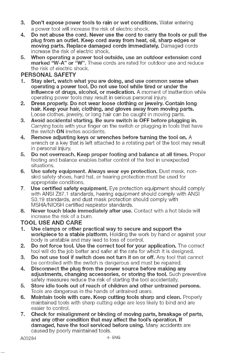
3, Don't expose power tooms to rain or wet conditions, Water entering
a power tool will increase the risk of electric shock.
4, Do not abuse the cord, Never use the cord to carry the rooms or pull the
plug from an outmet, Keep cord away from heat, oil, sharp edges or
moving parts, Replace damaged cords immediately,. Damaged cords
increase the risk of electric shock.
5, When operating a power too_ outside, use an outdoor extension cord
marked "W-A" or "W", These cords are rated for outdoor use and reduce
the risk of electric shock.
PERSONAL SAFETY
1, Stay alert, watch what you are doing, and use common sense when
operating a power tool, Do not use tool while tired or under the
influence of drugs, alcohom, or medication, A moment of inattention while
operating power tools may result in serious personal injury.
2, Dress proper{y. Do not wear loose c_otHng or jewemry. Contain mong
hair. Keep your hair, cmothing, and gloves away from moving parts,
Loose clothes, ]eweIry, or long hair can be caught in moving parts.
3, Avoid accidental starting, Be sure switch is OFF before pgugging in,
Carrying tools with your finger on the switch or plugging in tools that have
the switch ON invites accidents.
4, Remove adjusting keys or wrenches before turning the tool on, A
wrench or a key that is left attached to a rotating part of the tool may result
in personal injury:
5, Do not overreach, Keep proper footing and balance at aH times, Proper
footing and batance enables better control of the tool in unexpected
situations.
6, Use safety equipment. ABways wear eye protection, Dust mask, non-
skid safety shoes, hard hat, or hearing protection must be used for
appropriate conditions.
7. Use certified safety equipment, Eye protection equipment shouid comply
with ANSI Z87.1 standards, hearing equipment should comply with ANSI
$3.19 standards, and dust mask protection should comply with
MSHA/NIOSH certified respirator standards.
8, Never touch blade immediatemy after use, Contact with a hot blade will
increase the risk of a bum.
TOOL USE AND CARE
1, Use cmamps or other practicaB way to secure and support the
workpiece to a stable platform, Holding the work by hand or against your
body is unstable and may lead to Ioss of control
2, Do net force tool, Use the correct toomfor your appBication, The correct
tool will do the job better and safer at the rate for which it is designed.
3, Do not use toot if switch does not turn it on or off, Any toot that cannot
be controlled with the switch is dangerous and must be repaired.
4, Disconnect the plug from the power source before making any
adjustments, changing accessories, or storing the tool, Such preventive
safety measures reduce the risk of starting the toot accidentally.
5, Store idBetoo{s out of reach of children and other untrained persons,
Tools are dangerous in the hands of untrained users.
6, Maintain tooms with care, Keep cutting tooms sharp and cmean, Properly
maintained tools with sharp cutting edge are less likely to bind and are
easier to control
7, Check for misamignment or binding of moving parts, breakage of parts,
and any other condition that may affect the tool's operation, If
damaged, have the toomserviced before using, Many accidents are
caused by poorly maintained tools.
A03284
4- ENG
8, Use only accessories that are recommended by the manufacturer for
your model Accessories that may be suitable for one tool may become
hazardous when used on another tool.
9, Use only accessories recommended for this toomthat are sold by Sears
or a Craftsman outlet, Use of any accessories purchased elsewhere may
be hazardous.
SERVICE
1, Tool service must be performed only by qualified repair personnel
Service or maintenance performed by unqualified personnel could result
in a risk of injury.
2, When servicing a tool, use onmyidenticam replacement parts, Folmow
instructions in the Maintenance Section of this manual Use of
unauthorized parts or failure to follow Maintenance Instructions may
create a risk of shock or injury.
1, Hold toomby insulated gripping surfaces when performing an
operation where the cutting tooB may contact hidden wiring or its
own cord, Contact with a "live" wire will make exposed metal parts of
the tool "live" and shock the operator.
2, Keep blades sharp, Sharp blades will do the iob better and safer.
3, Keep hands away from cutting area. When sawing never reach
underneath or behind the material being cut for any reason.
4, When you have finished a cut be careful not to come into contact
with the Made, Turn off the motor immediately.
5. Never homdwork in your hand, lap, or against other parts of your
body when sawing, The saw may slip and the blade could contact the
body, causing injury.
Exercise extreme caution when bBind cutting, Blade
contact with foreign objects such as electrical wire, conduit,
ptumbing pipes, etc., could result in a risk of shock or serious
injury.
Some wood contains preservatives which can be toxic,
Take extra care to prevent inhamation and skin contact when
working with these materiaBs, Dust or fumes from this
operation could cause breathing problems, skin irritation or
other injuries.
This tool was designed for certain applications mikethose
described in this manual Incorrect use of this tool
could result in death or serious injury. DO NOT modify or use
this tool for any application for which it was NOT designed.
5-ENG A03284
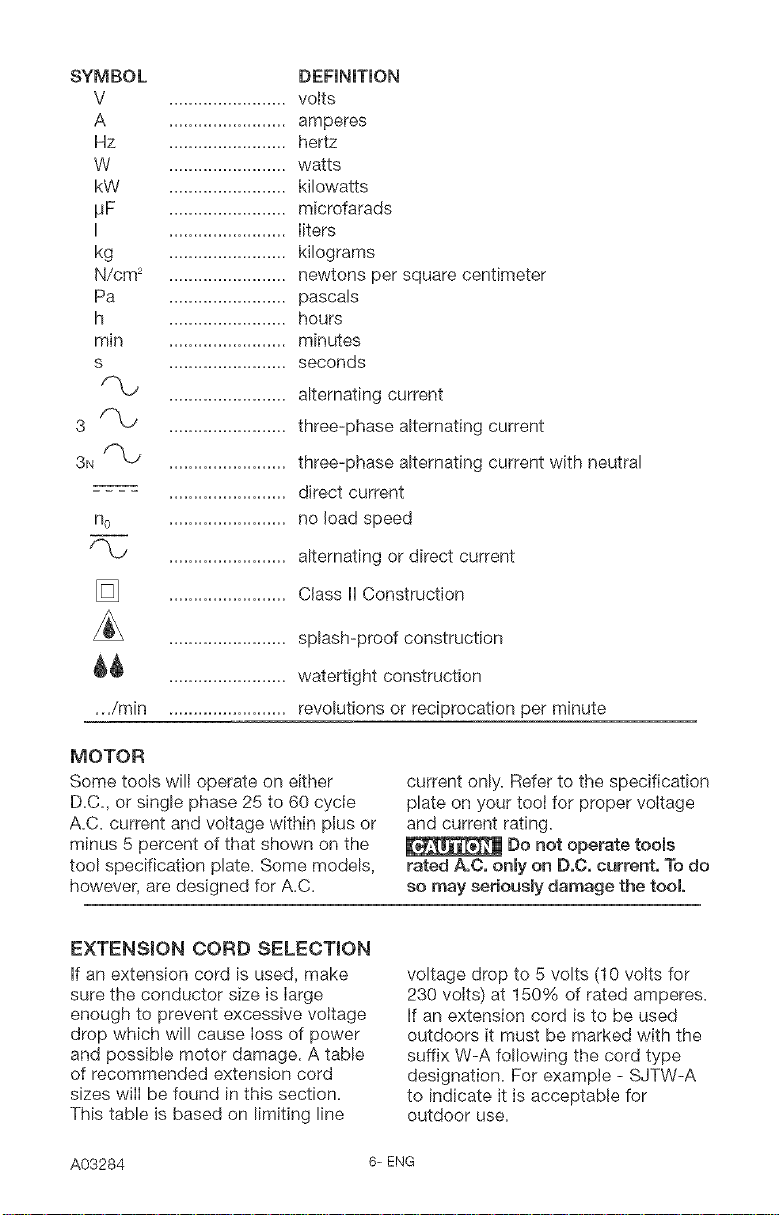
SYMBOL
V
A
Hz
W
kW
_F
........................ volts
........................ amperes
........................ hertz
........................ watts
........................ kilowatts
........................ microfarads
DEFINITION
........................ liters
kg
N/cm 2
Pa
h
min
s
........................ kilograms
........................ newtons per square centimeter
........................ pascals
........................ hours
........................ minutes
........................ seconds
........................ alternating current
3F'_
3N f-'LJ
........................ three-phase alternating current
........................ three-phase alternating current with neutral
........................ direct current
n o
........................ no load speed
........................ alternating or direct current
........................ Class li Construction
........................ splash-proof construction
_ ........................ watertight construction
._/min ........................ revolutions or reciprocation per minute
MOTOR
Some tools will operate on either
D.C. or single phase 25 to 60 cycle
A.C. current and voltage within plus or
minus 5 percent of that shown on the
tool specification plate. Some models,
however, are designed for A.C.
current only. Refer to the specification
plate on your tool for proper voltage
and current rating.
Do not operate tools
rated A,C. onmyon D,C, current, To do
so may seriously damage the tool
EXTENSION CORD SELECTmON
if an extension cord is used, make
sure the conductor size is large
enough to prevent excessive voltage
drop which will cause loss of power
and possible motor damage. A table
of recommended extension cord
sizes will be found in this section.
This table is based on limiting line
A03284 6= ENG
voltage drop to 5 volts (10 volts for
230 volts) at 150% of rated amperes.
if an extension cord is to be used
outdoors it must be marked with the
suffix W-A following the cord type
designation. For example - SJTW-A
to indicate it is acceptable for
outdoor use.

RECOMMENDEDEXTENSIONCORDSIZESFORUSEW_THPORTABLEELECTRICTOOLS
LengthofCordinFeet
115V25Ft_ 50Ft_100Ft, 150Ft_200Ft. 250Ft,300Ft_400Ft_500Ft,
230V50Ft_100Ft_200Ft. 300Ft_400Ft, 500Ft.600Ft_800Ft_1000Ft.
0-2 18 18 18 16 16 14 14 12 12
2-3 18 18 16 14 14 12 12 10 10
._ 3-4 18 18 16 14 12 12 10 10 8
4-5 18 18 14 12 12 10 10 8 8
8-6 18 16 14 12 10 10 8 8 6
6-8 18 16 12 10 10 8 6 6 6
8-10 18 14 12 10 8 8 6 6 4
®
10-12 16 14 10 8 8 6 6 4 4
z 2-14 16 12 10 8 6 6 6 4 2
14-16 16 12 10 8 6 6 4 4 2
16-18 14 12 8 8 6 4 4 2 2
18-20 14 12 8 6 6 4 4 2 2
FOREWORD
The variable angle reciprocating saw various other materials, such as
is designed for cutting wood up to plastics, fiberglass, hard rubber, etc.
12" thick, metal up to 3/4" thick and
INSTALLING THE BLADE
1. The reciprocating shaft must be
fully extended to permit access to
the keyless quick-change blade
release collar (A) Fig. 1. If
necessary, gently squeeze the
trigger switch to move the
reciprocating shaft to its
outermost position (as shown in
Fig.1).
Fig. I
Disconnect teem
from power source,
Pivot the guide shoe (B) Fig. 1,
forward to improve access to the
blade clamp.
To open the blade clamp, rotate
and hold the blade retease collar
(A) Fig, 2 or Fig, 3 counter-
clockwise (as viewed from the front
of the saw).
Fig. 2
7- ENG A03284
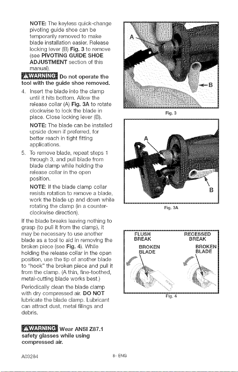
NOTE: The keytess quick-change
pivoting guide shoe can be
temporarily removed to make
blade installation easier. Release
locking lever (B) Fig. 3 to remove
(see PIVOTING GUIDE SHOE
ADJUSTMENT section of this
manual).
Do not operate the
roomwith the guide shoe removed.
4. insert the blade into the clamp
until it hits bottom. Allow the
release collar (A) Fig. 3A to rotate
clockwise to lock the blade in
place. Close locking lever (B).
NOTE: The blade can be installed
upside down if preferred, for
better reach in tight fitting
applications.
5. To remove blade, repeat steps 1
through 3, and pull blade from
blade clamp while holding the
release collar in the open
position.
NOTE: if the blade clamp collar
resists rotation to remove a blade,
work the blade up and down while
rotating the clamp (in a counter-
clockwise direction).
if the blade breaks leaving nothing to
grasp (to pull it from the clamp), it
may be necessary to use another
blade as a tool to aid in removing the
broken piece (see Fig. 4). While
holding the release collar in the open
position, use the tip of another blade
to "hook" the broken piece and pull it
from the clamp. (A thin, fine-toothed,
metal-cutting blade works best.)
Periodically clean the blade clamp
with dry compressed air. DO NOT
lubricate the blade clamp. Lubricant
can attract dust, metal filings and
debris.
A
FLUSH
BREAK
BROKEN
BLADE
Fig. 3
B
Fig. 3A
RECESSED
BREAK
BROKEN
BLADE
Fig. 4
Wear ANSI Z87,1
safety glasses while using
compressed air.
A03284 8- ENG
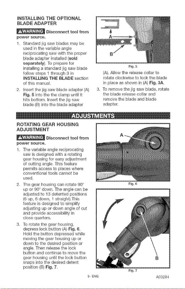
INSTALLING THE OPTmONAL
BLADE ADAPTER
Disconnect tool from
power source,
1, Standard jig saw blades may be
used in the vadabIe angle
reciprocating saw with the proper
blade adapter installed (sold
separately), To prepare for
installing a standard jig saw blade
follow steps 1 through 3 in
INSTALLING THE BLADE section
of this manual,
2, Insert the jig saw blade adapter (A)
Fig. 5 into the the clamp untiI it
hits bottom, Insert the jig saw
blade (B) into the blade adapter
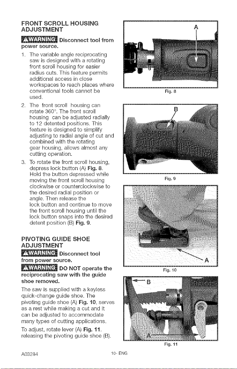
ROTATING GEAR HOUSING
ADJUSTMENT
Disconnect tool from
power source,
1, The variable angIe reciprocating
saw is designed with a rotating
gear housing for easy adjustment
of cutting angle. This feature
permits access to places where
conventional tools cannot be
used,
The gear housing can rotate 90°
up or 90 ° down, The angle can be
adjusted to 13 detented positions
(6 up, 6 down, 1 straight),This
feature is designed to simplify
adjusting up or down angle of cut
and provide accessibility in
close quarters,
To rotate the gear housing,
depress lock button (A) Fig. 6,
Hotd the button depressed while
moving the gear housing up or
down to the desired position or
angle, Then reIease the lock
button and continue to move the
gear housing until the Iock button
snaps into the desired detent
position (B) Fig. 7,
A'
Fig, 5
(A)_Allow the release collar to
rotate clockwise to lock the blade
in place as shown in (A) Fig. 3A.
3, To remove the jig saw blade, rotate
the blade release collar and
remove the blade and blade
adapter,
Fig. 6
Fig. 7
9- ENG
A03284
FRONT SCROLL HOUSING
ADJUSTMENT
Disconnect tool from
power source,
1. The variable angle reciprocating
saw is designed with a rotating
front scroll housing for easier
radius cuts. This feature permits
additional access in close
workspaces to reach places where
conventional tools cannot be
used.
The front scroll housing can
rotate 360°. The front scroll
housing can be adjusted radially
to 12 detented positions. This
feature is designed to simplify
adjusting to radial angle of cut and
combined with the rotating
gear housing, allows almost any
cutting operation.
To rotate the front scroll housing,
depress lock button (A) Fig, 8.
Hold the button depressed while
moving the front scroll housing
clockwise or counterclockwise to
the desired radial position or
angle. Then release the
lock button and continue to move
the front scroll housing until the
lock button snaps into the desired
detent position (B) Fig, 9.
A
Fig, 8
B
Fig. 9
PIVOTING GUIDE SHOE
ADJUSTMENT
Disconnect tool
from power source,
DO NOT operate the
reciprocating saw with the guide
shoe removed,
The saw is supplied with a keyiess
quick-change guide shoe. The
pivoting guide shoe (A) Fig, f0, serves
as a rest while making a cut and it
can be adjusted to accommodate
many types of cutting applications.
To adjust, rotate lever (A) Fig, 11.
releasing the pivoting guide shoe (B).
A03284 10-ENG
Fig. 10
Fig. 11
Adjust to one of the four positions
and close lever (A) Fig. 12. After
adjusting, make sure the locking lever
is completely closed in the locked
position (A) Fig. 12.
NOTE: DO NOT force the locking
lever closed. Adjust shoe enough to
allow the lever to lock in position
without force.
Fig. 12
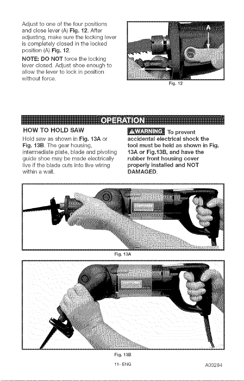
HOW TO HOLD SAW
Hold saw as shown in Fig. 13A or
Fig. 13Ba The gear housing,
intermediate plate, blade and pivoting
guide shoe may be made electrically
live if the blade cuts into live wiring
within a wail
To prevent
accidental electricaB shock the
tooB must be held as shown in Fig,
i3A or Fig.i3B, and have the
rubber front housing cover
properly installed and NOT
DAMAGED=
Fig. 13A
Fig, 13B
11- ENG A03284
 Loading...