

Craftsman 351249520, 351249510 Owner’s Manual
Operator's Manual
COPY CRAFTER
Model No.
351.249510
351.249520
CAUTION:
Read and follow all Safety
Rules and Operating
Instructions before First
Use of this Product.
Sears, Roebuck and Co., Hoffman Estates, IL 60179 U.S.A.
www.seaPs.co_c_+,_man
18234,01 Draft (09/03/03)
• Safety
• Assembly
• Operation
• Maintenance
• Parts List
• EspaRol
Warranty ......................................... 2
Safety Rules .................................... 2-3
Unpacking ....................................... 3
Assembly ...................................... 4-6
Operation ...................................... 6-7
Maintenance ..................................... 7
Troubleshooting ................................... 8
Parts Illustration and List ........................ '10-13
Espariol ...................................... 14-23
FULL ONE YEAR WARRANTY
If this product fails due to a defect in material or workmanship
within one year from the date of purchase, Sears will at its
option repair or replace it free of charge. Contact your nearest
Sears Service Center (1-80O-4-MY-HOME) to arrange for
product repair, or return this product to place of purchase for
replacement.
If this product is used for commercialor rental purposes, this
warranty will apply for 90 days from the date of purchase.
This warranty applies only while this product isused in the
United States.
This warranty gives youspecific legal rights and you may also
have other rightswhichvary from state to state.
Sears, Roebuck and Co., Dept. 817WA, Hoffman
Estates, IL 60179
CAUTION: Always follow proper operating procedures as
defined in this manual -- even if you are familiar withuse of
this or similartools. Remember that being careless for even a
fraction of a second can result insevere personal injury.
BE PREPARED FOR JOB
• Wear proper apparel. Do not wear loose clothing,gloves,
neckties, rings, bracelets or other jewelry which may get
caught in moving parts of machine.
• Wear protective hair covering to contain long hair.
• Wear safety shoes with non-slip soles.
• Wear safety glasses complying with United States ANSI
Z87.1. Everyday glasses have only impact resistant lenses.
They are NOT safety glasses.
• Wear face mask or dust mask if operation is dusty.
• Be alert and think clearly Never operate power tools when
tired, intoxicated or when taking medications that cause
drowsiness.
PREPARE WORK AREA FOR JOB
Keepwork area clean, Clutteredworkareas inviteaccidents,
Do notuse powertools in dangerous environments, Do not
use power toolsin damp or wet locations,Do not expose
powertools to rain,
Work area shouldbe properlylighted.
• Keep visitors at a safe distance from work area.
• Keep childrenout ofworkplace. Make workshop childproof.
Use padlocks, master switches or remove switch keys to
prevent any unintentional use of power tools.
TOOL SHOULD BE MAINTAINED
• Always unpluglathe prior to inspection.
• Consult manual for specific maintaining and adjustingpro-
cedures.
• Keep tool lubricated and clean for safest operation.
• Keep all parts in workingorder.Check to determine that
the guard or other parts willoperate properly and perform
their intended function.
• Check for damaged parts. Check for alignmentof moving
parts, binding,breakage, mounting and any other condition
that may affect a tool'soperation.
• A guard or otherpart that is damaged should be properly
repaired or replaced. Do not perform makeshift repairs.
(Use parts list providedto order replacement parts.)
• Never adjustcopy crafter while lathe is running. Disconnect
powerto avoidaccidental start-up.
Keep cuttingtools sharp for efficientand safest operation.
KNOW HOWTO USE TOOL
Use righttoolforjob. Do notforce tool or attachment to do
ajob for which it was not designed.
Avoid accidental start-up. Make sure that the tool is in the
"off" positionbefore pluggingin,turning on safety discon-
nect or activating breakers.
Do notforce tool. It willwork most efficientlyat the rate for
whichit was designed.
Keephandsaway from chuck,centersand othermovingparts.
Never leave tool running unattended. Turn the power off
and do not leave tool until it comes toa complete stop.
Do not overreach. Keep properfooting and balance.
Never stand on tool. Serious injurycouldoccur iftool is
tipped or if centers are unintentionallycontacted.
Knowyourtool. Learn the tool'soperation, application and
specificlimitations.
Handle workpiece correctly.Mount firmly in holding
devices. Protect handsfrom possible injury.
Turn machine off if workplace splitsor becomes loose.
Use cuttingtools as recommended in "Operation."
WARNING: Foryourown safety,do notoperateyourcopy
crafteruntilit is completelyassembledand installedaccordingto
instructions.
PROTECTION: EYES, HANDS, FACE, BODY, EARS
If any part ofyour copycrafter is missing,malfunctioning,
or has been damaged or broken, cease operating immedi-
ately untilthe particular part is properlyrepaired or
replaced.
• Wear safetygogglesthat comply with UnitedStatesANSI
Z87.1 and a face shieldordustmask ifoperationisdusty.
Wear ear plugsor muffsduringextendedpedodsofoperation.
Small loose pieces of wood or other objects that contact a
spinningworkpieca can be propelledat very high speed.
This can be avoided by keeping the work area clean.
• Clean copycrafterand la_e ofalltools,wood scraps,etc.,
exceptworkpiecaand necessarytoolsbeforestartingopera-
tJon.
Never place your face or body in line with the chuck or
faceplate.
© Seam,Roebuckand Co.
2
• Never place your fingersor hands in path of cutting tools.
• Never reach in back of the workpiece witheither hand to
support the piece, remove wood scraps, or for any other
reason.Avoid awkward operations and hand positions
where a sudden slip could cause fingers or hand to move
intoa spinning workpiece.
• If the workplace splitsor isdamaged in any way, turn lathe
OFF and removethe workplace from the holders. Discard
damaged workpiece and start with a new piece of wood.
• Use extra care when turningwood withtwisted grain or
wood that is twisted or bowed -- it may cut unevenlyor
wobbleexcessively.
KNOWYOUR CUTrlNG TOOLS
• Dull, gummy, improperly sharpened or set cutting tools can
cause vibration and chatterduring cutting operations.
Minimize potential injuryby proper care of tools and regu-
lar machine maintenance.
THINK SAFETY
Safety is a combination of operator common sense and alert-
ness at all times when the lathe is being used.
• For your own safety, read all rules and precautions inthe
operator's manual before using this tool.
For eye protection,wear safety glasses complyingwith
United States ANSI Z87.1.
Do notwear loose clothing, gloves, neckties, rings,
bracelets or other jewelry that could get caught in moving
parts ofmachine or workpiece.Wear protective hair cover-
ing to contain long hair.
• Tighten all clamps, fixtures and tailstock before applying
power. Check to make sure that all tools andwrenches
have been removed.
With switchoff, rotate workplace by hand to make sure
that there is adequate clearance. Start the machine on
lowest speed settingto verify that the workplace is secure.
Do not mount any workpieces that have splits or knots.
Never attemptto remounta between-centersturningifthe
originalcenters on theturning have been altered or removed.
When remounting a between-centers turningthat has non-
altered original centers, make sure that the speed is at the
lowest settingfor start-up.
• Use extra cautionwhen mounting a between-cantere turn-
ing to the faceplate, or a faceplate turning to between-cen-
ters, forsecondary operations. Make sure that the speed is
at the lowest settingfor start-up.
• Never perform any operation with this tool where the work-
piece is hand-held. Do not mount a reamer, milling cutter,
drillbit, wire wheel or buffingwheel to the headstockspin-
dle.
• Never run the spindlein the wrong direction.The cutting
tool couldbe pulled from your hands. The workplace
should always turn towards the operator.
• For spindleturning, ALWAYS positionthe tool rest abovethe
centedine ofthe workpieceand spindle (approximately_k").
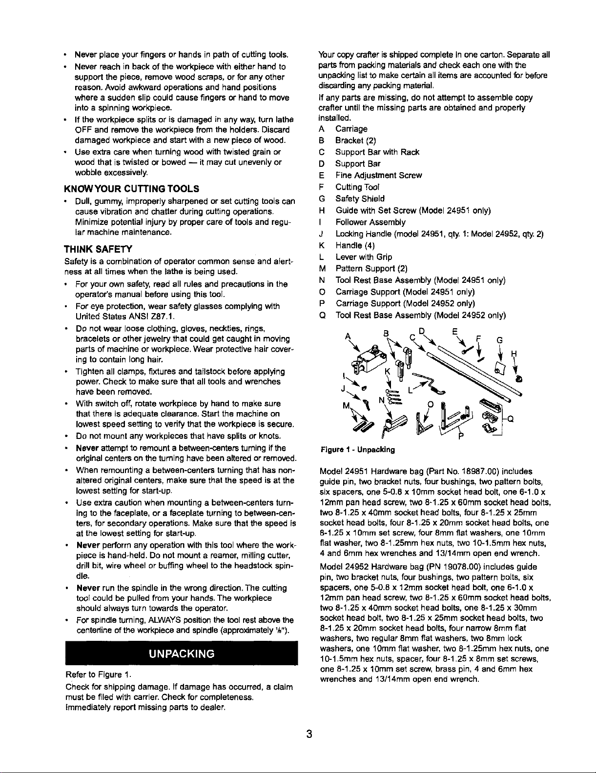
Refer to Figure 1.
Check for shipping damage. If damage has occurred,a claim
must be filed with carrier.Check forcompleteness.
immediately report missingparts to dealer.
Your copycrafteris shippedcomplete inone carton.Separate all
partsfrom packingmaterialsand check each onewiththe
unpackinglistto make certain all itemsare accountedfor before
discardingany packingmaterial,
if any parts are missing, do not attempt to assemble copy
crafter untilthe missing parts are obtained and properly
installed.
A Carriage
B Bracket (2)
C Support Bar with Rack
D Support Bar
E Fine Adjustment Screw
F Cutting Tool
G Safety Shield
H Guide with Set Screw (Model 24951 only)
I Follower Assembly
J Locking Handle (model 24951, qty 1: Model 24952, qty. 2)
K Handle (4)
L Lever with Grip
M Pattern Support (2)
N Tool Rest Base Assembly (Model 24951 only)
O Carriage Support (Model 24951 only)
P Carriage Support (Model 24952 only)
Q Tool Rest Base Assembly (Model 24952 only)
A B D E
I
Figure1 - Unpacking
Model 24951 Hardware bag (Part No. 18987.00) includes
guide pin, two bracket nuts,four bushings,two pattern bolts,
six spacers, one 5-0.8 x 10mm socket head bolt, one 6-1.0 x
12mm pan head screw,two 8-1.25 x 60ram sockethead bolts,
two 8-1.25 x 40mm sockethead bolts,four 8-1.25 x 25ram
socket head bolts,four 8-1,25 x 20mm socket head bolts,one
8-1.25 x 10ram set screw,four 8mm fiat washers, one 10ram
fiat washer, two 8-1.25mm hex nuts, two 10-1.5mm hex nuts,
4 and 6ram hexwrenches and 13/14mm open end wrench.
Model 24952 Hardware bag (PN 19078.00) includesguide
pin, two bracketnuts, four bushings, two pattern bolts, six
spacers, one 5-0.8 x 12ram socket head bolt, one 6-1.0 x
12mm pan head screw, two 8-1.25 x 60mm socket head bolts,
two 8-1.25 x 40ram socket head bolts, one 8-1.25 x 30mm
socket head bolt, two 8-1.25 x 25mm socket head bolts, two
8-1.25 x 20mm socket head bolts, four narrow 8ram fiat
washers, two regular 8mm flat washers, two 8ram lock
washers, one 10mm fiat washer, two 8-1.25mm hex nuts, one
10-1.5mm hex nuts, spacer, four 8-1.25 x 8ram set screws,
one 8-1.25 x 10mm set screw, brass pin, 4 and 6ram hex
wrenches and 13/14mm open end wrench.
RefertoFigures1-9.
CAUTION:Donotattemptassemblyifpartsaremissing.
Usethismanualtoorderreplacementparts.
• Removeallcomponentsfromtheshippingcartonandverify
againstthepartslistabove.Cleaneachcomponentand
removeshippingpreservatives(coatings)asrequired.
NOTE: Before assembling copy crafter, make sure that lathe
is secured to a suitableworkbench or stand.
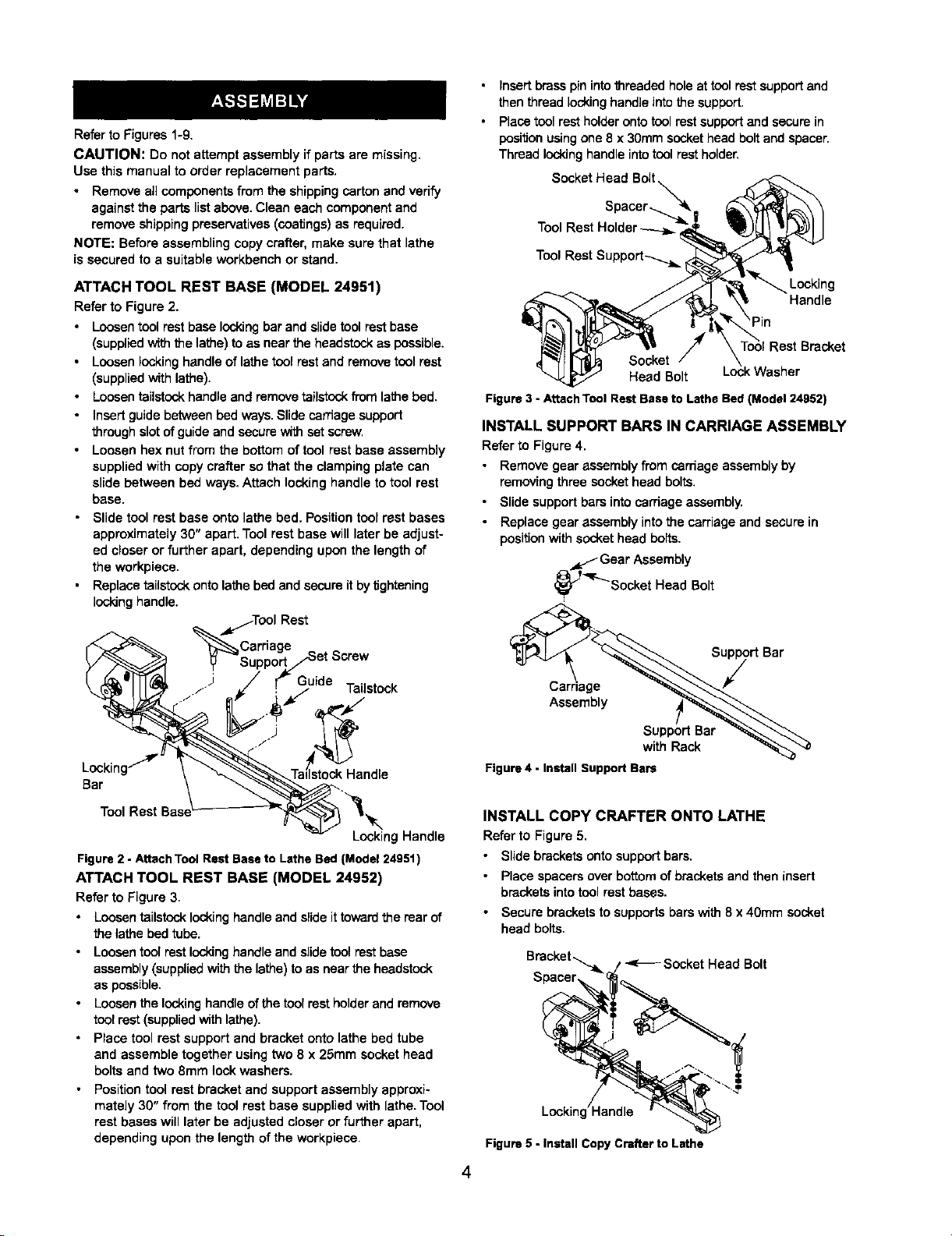
ATTACH TOOL REST BASE {MODEL 24951)
Refer to Figure 2.
• Loosentool rest base lockingbarand slidetoolrest base
(suppliedwith the lathe)to as nearthe headstockas possible,
• Loosen locking handleof lathe tool rest and remove tool rest
(suppliedwithlathe).
• Loosentailstookhandleand remove tailstookfrom lathe bed.
• Insert guide between bedways.Slide carnage support
through slotof guideand secure with set screw.
• Loosen hex nut from the bottom of tool restbase assembly
suppliedwith copycrafter so that the clamping plate can
slide between bed ways, Attach locking handle to tool rest
base.
• Slide tool rest base onto lathe bed, Positiontool rest bases
approximately 30" apart, Tool rest base will later be adjust-
ed closer or further apart, depending upon the length of
the workpieca.
• Replace tsilstock onto lathe bed and secureitby tightening
lockinghandle.
_/TOOl Rest
_Carriage Screw
J Guide
:" Tailstock
Insertbrasspin intothreaded hole at toolrest supportand
then thread locking handleinto the support.
Placetool rest holderontotool rest supportand securein
positionusingone 8 x 30ram sockethead boltand spacer.
Thread lockinghandle intotool restholder.
Socket H::dac::J_.
Tool Rest Holder_
_'_ Looking
t, Handle
\Pin
ToolRest Bracket
Head Bolt
Figure3 - AttachTool RestBaseto Lathe Bed(Model 24952)
INSTALL SUPPORT BARS IN CARRIAGE ASSEMBLY
Refer to Figure 4,
• Remove gear assembly from carriage assemblyby
removingthree sockethead bolts.
• Slide supportbars intocarriage assembly.
• Replace gear assembly intothe carriage and securein
positionwith socket head bolts,
_L.f Gear Assembly
'_'_Socket Heed Belt
Loc_kWasher
Bar
sT.
Assembly
Lockin,
Bar
Tool Rest
Figure2 - AttachTool RestBaseto Lathe Bed(Model24951)
ATTACH TOOL REST BASE (MODEL 24952)
Refer to Figure 3.
Loosentailstocklockinghandleand slide ittowardthe rear of
the lathe bed tube.
Loosentool rest lockinghandle and slidetool rest base
assembly(suppliedwith the lathe)to as near the headstock
as possible.
Loosenthe lockinghandle ofthetoolrestholder and remove
toolrest (suppliedwith lathe).
Place tool rest supportand bracket onto lathe bed tube
and assemble together usingtwo 8 x 25mm sockethead
bolts and two 8ram lockwashers.
Positiontool rest bracketand support assembly approxi-
mately 30" from the tool rest base suppliedwith lathe. Tool
rest bases will later be adjusted closer or further apart,
depending upon the lengthof the workpiece.
/J _to_H_a
Ta ndle
LockingHandle
Support Bar
with Rack
Figure 4 - Install Support Bars
INSTALL COPY CRAFTER ONTO LATHE
Refer to Figure 5,
• Slide bracketsonto supportbars,
• Place spacersover bottomof bracketsand then insert
bracketsinto tool rest bases,
• Secure bracketsto supportsbarswith 8 x 40ram socket
head bolts,
BsmpCkce_r_!_ d Bolt
Figure5 - Install CopyCrafterto Lathe
4
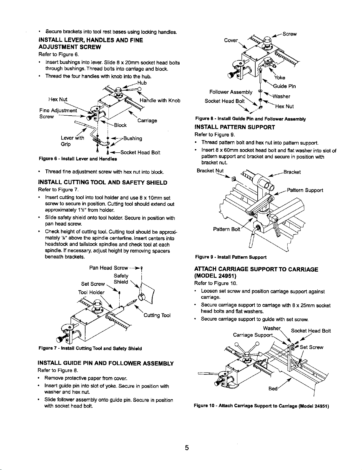
• ,Secure bracketsinto tool rest bases using lockinghandles.
INSTALL LEVER, HANDLES AND FINE
ADJUSTMENT SCREW
Refer to Figure 6.
• Insert bushingsinto lever. Slide 8 x 20mm sockethead bolts
through bushings.Thread boltsinto carriage and block.
• Thread the four handles withknob intothe hub.
Hex Nut
Fine Adj
Screw
Leverwitch i
Grip
Figure6 - Install Leverand Handles
• Thread fine adjustment screw with hex nut into block.
INSTALL CUTTING TOOL AND SAFETY SHIELD
Refer to Figure 7.
Insert cuttingtoolinto tool holder and use 8 x 10mm set
screwto secure in position.Cuttingtool shouldextendout
approximately1W' from holder.
Slide safety shieldonto tool holder.Secure in positionwith
pan head screw.
Check height ofcuttingtool Cuffingtoot shouldbe approxi-
mately ',_"above the spindlecentedine.Insertcanters into
headstockand tailstockspindlesand check tool at each
spindle.If necessary,adjust heightby removingspacers
beneath brackets.
L
,-<_Socket Head Bolt
Carriage
C_ _ Scre_
Yoke
"_'N3uide Pin
FollowerAssembly _,,_
.L "_-Washer
Socket Head Bolt _ _'_r-_
",_ "_,_-- Hex Nut
Figure8 - Install GuidePin and FollowerAssembly
INSTALL PATTERN SUPPORT
Refer to Figure 9.
• Thread pattern boltand hex nut into pattern support.
Insert8 x 60mm socket head boltand fiatwasher intoslotof
pattern support and bracket and secure in position with
bracketnut.
Bracket Nut _Bracket
Support
Figure 9 - Install Pattern Support
Pan Head Screw--->T
Safety i
ToSoo:tHSo_rd';_'-_ hield "_k_
'_r'_"Cutting Tool
Figure7 - InstallCuttingTooland SafetyShield
INSTALL GUIDE PIN AND FOLLOWER ASSEMBLY
Refer to Figure 8.
Remove protectivepaper from cover.
Insert guidepin intoslot of yoke. Secure in positionwith
washer and hex nut.
• Slide follower assembly onto guide pin.Secure in position
withsocket head bolt.
ATTACH CARRIAGE SUPPORT TO CARRIAGE
(MODEL 24951)
Refer to Figure 10.
• Loosen set screw and position carriagesupportagainst
carriage.
• Secure carriage supportto carriage with8 x 25mm socket
head boltsand fiat washers.
• Secure carriage supportto guide with set screw.
Washer Socket Head Bolt
Carriage Support_ _,_
Bed
Figure 10 - Attach Carriage Support to Carriage (Model 24951)
5
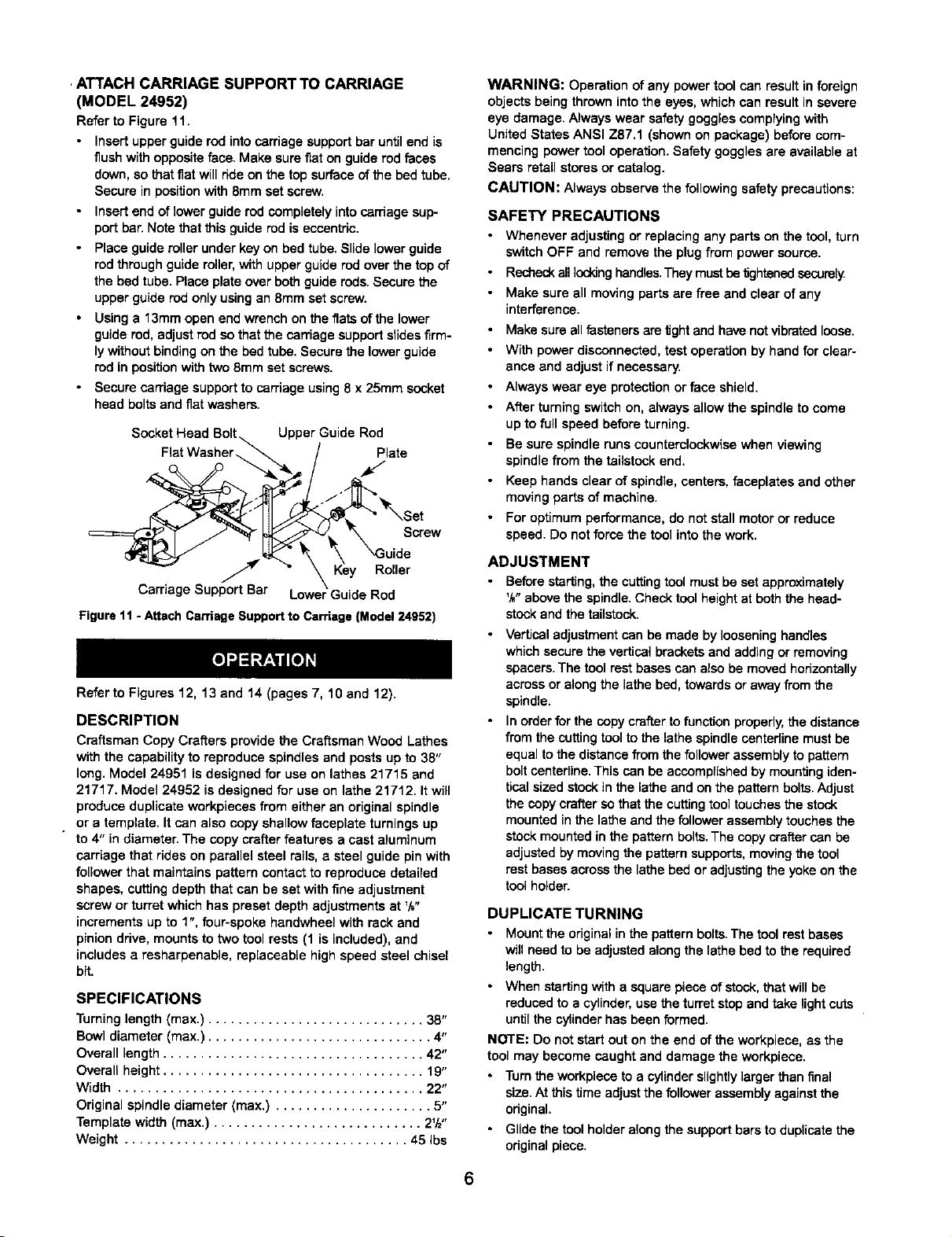
, ATTACH CARRIAGE SUPPORT TO CARRIAGE
(MODEL 24952)
Refer to Figure 11.
Insert upperguide rod intocarriage supportbar untilend is
flushwith oppositeface, Make surefiat on guide rod faces
down,so that flat will ride on the top surfaceof the bed tube,
Secure in positionwith 8ramset screw,
Insertend of lower guide rod completelyinto carriage sup-
portbar.Note that this guide rod is eccentric.
Place guideroller under key on bed tube.Slide lowerguide
rodthroughguide roller,with upper guide rod overthe top of
the bed tube.Race plateover bothguide rods.Secure the
upper guide rod only usingan 8mm set screw.
Using a 13mm open end wrench on the fiatsof the lower
guide red, adjust rod so thatthe carriage supportslidesfirm-
lywithoutbinding on the bed tube. Secure the lowerguide
rodin positionwith two 8mm set screws.
• Secure carriage supportto carriage using8 x 25ram socket
head boltsand flatwashers.
Socket Head Upper Guide Rod
Fiat Washer Plate
Screw
Key Roller
Carriage Support Bar Lower Guide Rod
Figure11- Attach Caniage Supportto Carriage (Model24952)
Refar to Figures 12, 13 and 14 (pages 7, 10 and 12).
DESCRIPTION
Craftsman Copy Crefters provide the Craftsman Wood Lathes
with the capabilityto reproduce spindles and posts up to 38"
long. Model 24951 is designed for use on lathes 21715 end
21717. Model 24952 is designed for use on lathe 21712. It will
produce duplicate workpieces from either an original spindle
or a template. It can also copyshallow faceplate turningsup
to 4" in diameter. The copy crafterfeatures a cast aluminum
carriage that rides on parallel steel rails, a steel guide pinwith
followerthat maintains pattern contactto reproduce detailed
shapes, cutting depth that can be set withfine adjustment
screw or turret which has preset depth adjustments at V_"
increments up to 1", four-spoke handwheel with reckand
pinion drive, mounts to two tool rests(1 is included), and
includesa resharpenable, replaceable high speed steel chisel
bit.
SPECIFICATIONS
Turninglength (max.) ............................. 38"
Bowl diameter (max.) .............................. 4"
Overall length ................................... 42"
Overall height ................................... 19"
Width ......................................... 22"
Original spindlediameter (max.) ..................... 5"
Template width (max.) ............................ 2W'
Weight ...................................... 45 Ibs
WARNING: Operation of any power tool can resultin foreign
objects being thrown intothe eyes, which can result in severe
eye damage. Always wear safety goggles complyingwith
United States ANSI Z87.1 (shown on package) before com-
mencing powertool operation.Safety goggles are availableat
Sears retail stores or catalog.
CAUTION: Always observe the following safety precautions:
SAFETY PRECAUTIONS
• Whenever adjusting or replacing any parts on the tool, turn
switchOFF and remove the plugfrom power source.
• Recheckall lockinghandles.They must betightened secarely
• Make sure all moving partsare free and clear of any
interference.
• Make sure allfasteners are tightand havenot vibratedloose.
• With power disconnected,test operation by hand for clear-
ance and adjust if necessary.
• Always wear eye protectionor face shield.
• After turningswitchon, always allow the spindleto come
up to full speed before turning.
• Be sure spindle runs counterclockwisewhen viewing
spindle from the tailstockend.
• Keep hands clearof spindle, centers,faceplatas and other
movingparts of machine.
• For optimum performance, do not stall motoror reduce
speed. Do not force the tool intothe work.
ADJUSTMENT
• Before starting,the cuffingtool must be set approximately
%"above the spindle.Check tool heightat both the head-
stockand the tailstock.
Verticaladjustment can be made by looseninghandles
whichsecure the verticalbrackets and adding or removing
spacers.The tool restbases canalso be moved horizontally
acrossor along the lathebed, towardsor away fromthe
spindle.
In orderfor the copy crafter to function properly,the distance
fromthe cuttingtool tothe lathe spindlecentadine must be
equal tothe distancefrom the follower assembly to pattern
boltcentedine.This can be accomplishedby mountingiden-
ticalsized stockin the lathe and on the patternbolts.Adjust
the copy crafter so that the cuffingtool touches the stock
mounted inthe latheand the follower assemblytouchesthe
stockmounted in the patternbolts.The copycrafter can be
adjusted bymoving the pattern supports,movingthe tool
rest basesacross the lathe bedor adjustingthe yokeon the
toolholder.
DUPLICATE TURNING
• Mount the originalinthe pattern bolts.The tool rest bases
will need to be adjustedalong the lathe bed to the required
length.
• When startingwitha squarepiece of stock,that willbe
reduced to a cylinder, use the turretstopand take light cuts
untilthe cylinderhas beenformed.
NOTE: Do not startout on the end of the workpiece,as the
tool may become caught and damage the workpiece.
• Turn the workpieca to a cylinderslightlylarger than final
size. At this time adjust the follower assembly against the
odginal.
• Glide the tool holder along the supportbars to duplicate the
odginal piece.
6
NOTE: Sharp corners and small grooves will only be partially
duplicated by the copy crafter.The follower assembly will
need to be removed. Usingcalipers, transfermeasurements
from originalto duplicate, and clean up grooves and corners
using fine adjustment screw on carriage.
MISCELLANEOUS OPERATIONS
• The copy craftercan also be used to taper workpieces.To
dothis, offsetthe tool rest bases.
• The copy craftercan be mounted acrossthe bed for copying
ofbowls,cups, etc. byrepositioningtoolrest bases.
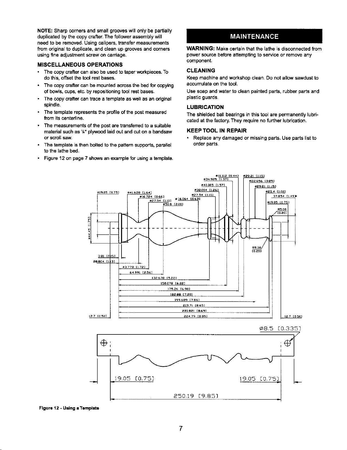
• The copy craftercan trace a template as well as an original
spindle.
• The template representsthe profileof the postmeasured
from itscentedine.
• The measurements of the post are transferredto a suitable
material such as '/," plywood laid out and cuton a band,saw
or scrollsaw.
• The template is then bolted to the pattern supports,parellel
tothe lathe bed.
• Figure 12 on page 7 showsan example br usinga template.
=19.05 [07'5] _4L628 [1.641
¢I6 724 COGG]
_2794 _110_
WARNING: Make certain that the lathe is disconnectedfrom
power source before attemptingto service or removeany
component.
CLEANING
Keep machine and workshop clean. Do not allowsawdustto
accumulate on the tool.
Use soap and water to clean painted parts, rubberparts and
plastic guards.
LUBRICATION
The shielded ball bearings in thistoolare permanently lubri-
cated at the factory. They require no further lubrication.
KEEP TOOL IN REPAIR
Replace any damaged or missingparts. Use parts list to
order parts.
¢,11112 [0441 ,_292] [115]
¢34 '925 [1373
_ 16064 [063]
'a40005 C157]
_32.004 [1.26]
,1,27 94 [1¸101
,_29.2_ It 1_3
m254 c]oo]
37.8_4 C149_
=190_ [0751
28 8134
t2.7 [0.50_
\
/-
[020]
[1 3]
43778 [172]
64991 [2.561
132 678 [5_2]
156.078 [(= 22]
] 75.26 [6903
182_8 [720]
199¸689 [786_
2197t [865]
Z268_t [869J
224 79 [8853
127 C0503
_8.5 [0.335]
.19.05[0.75] 19.05C0.7 I W [.,_
Figure 12 - Using a Template
250.19 [9,85]
7
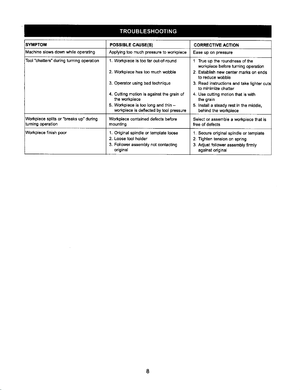
SYMPTOM CORRECTIVE ACTION
Machine slows down while operating Ease up on pressure
Tool =chatters" duringturningoperation
Workpiece splitsor "breaks up"during Select or assemble a workpiece that is
turningoperation free of defects
POSSIBLE CAUSE(S)
Applying too much pressureto workpiece
1. Workpiece is too far out-of-round
2. Workpiece has too muchwobble
3. Operator usingbad technique
4. Cutting motion is against the grain of
the workpiece
5. Workpiece is too longand thin-
work-pieceisdeflected bytool pressure
Workpiece contained defects before
mounting
1 True up the roundness of the
workpiece before turning operation
2. Establishnew center marks on ends
to reduce wobble
3. Read instructionsand take lightercut.,
to minimize chatter
4. Use cutting motionthat iswith
the grain
5. Install a steady rest in the middle,
behind the workpiece
Workpiece finish poor 1. Secure original spindleor template
1. Original spindleor template loose
2. Loose tool holder
3. Follower assembly notcontacting
original
2. Tighten tension on spring
3. Adjust follower assembly firmly
against original
8
 Loading...