

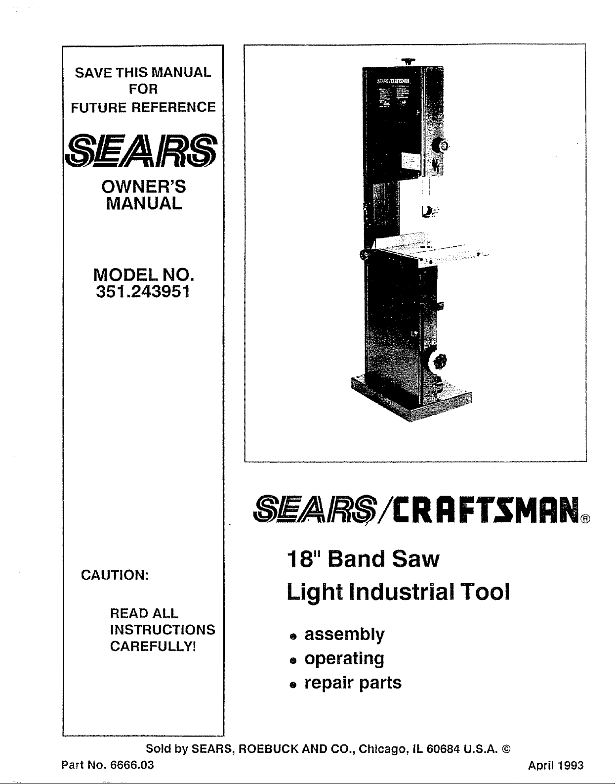
Craftsman 351243951 Owner’s Manual
SAVE THIS MANUAL
FOR
FUTURE REFERENCE
IS_EA/R8
OWNER'S
MANUAL
MODEL NO.
351.243951
8_A/,_,_/I: RI:1FTSMI:1N®
18" Band Saw
CAUTION:
Light Industrial Tool
READ ALL
INSTRUCTIONS
CAREFU LLY!
Sold by SEARS, ROEBUCK AND CO., Chicago, IL 60684 U.S.A. ©
Part Noo 6666.03 April 1993
o assembly
• operating
. repair parts
FULL ONE-YEAR WARRANTY ON SEARS/CRAFTSMAN 18" Band Saw
If, within one full year from the date of purchase this Sears Craftsman 18" Band Saw fails due to a
defect in material or workmanship, Sears will repair it free of charge.
WARRANTY SERVICE 1SAVAILABLE BY SIMPLY RETURNING THE BAND SAW TO THE
NEAREST SEARS STORE OR SERVICE CENTER THROUGHOUT THE UNITED STATES.
This warranty gives you specific legal rights, and you may have other rights which vary from state
to state.
SEARS, ROEBUCK AND CO., D/817 WA, 3333 Beverly Road, Hofman Estates, IL 60179
GENERAL SAFETY INSTRUCTIONS FOR POWER TOOLS
BEFORE ANY WORK IS DONE READ THE CAU-
TIONS LISTED BELOW CAREFULLY. WORKING
SAFELY PREVENTS ACCIDENTS.
OPERATOR SHOULD BE PREPARED FOR JOB:
a. Wear proper apparel. Do not wear loose clothing,
gloves, neckties, rings, bracelets or other jewelry
which may get caught in moving parts of the saw,
b Wear protective hair covering to contain long hair
c. Wear safety shoes with non-slip sole&
d, Wear safety glasses. Everyday glasses have only
impact resistant lenses. They are not safety glasses°
e Wear face mask or dust mask if ct_ing operation
is dusty°
f. Be alert and think clearly. Never operate power
tools when tired, intoxicated or when taking
medications that cause drowsiness,,
WORK AREA SHOULD BE READY FOR JOB:
a Keep work area clean. Cluttered work areas and
workbenches invite accidents,
b Do not use power tools in dangerous environ-
ments. Do not use power tools in damp or wet
location& Do not expose power tools to rain.
c Work area should be properly lighted,
d. The proper electrical outlet should beavailabIefor
the logic A three-prong plug should be plugged
directly into a properly grounded, three-prong
receptacle.
e Extension cords should have a grounding prong
and the three wires of the extension cord should be
the correct gauge,
f Keep visitors a safe distance from work area.
g. Keep children out of workplace° Make workshop
childproof,, Use padlocks, master switches and
remove starter keys to prevent any unintentional
use of power tools
SAW SHOULD BE MAINTAINED:
a, Always unplug band saw prior to inspection,
b Consult the owner's manual for specific maintain-
ing and adjusting procedures
c Keep band saw lubricated.,
d Use sharp blades and keep the saw clean for safest
operation.
e., Remove adjusting keys and wrenches. Form
habit of checking to see that keys and adjusting
wrenches are removed before turning on saw_
f Keep all guards in place and in working order.
g, Keep all parts in working order. Check to deter-
mine that the guard or other parts will operate
properly and perform their intended function_
ho Check for damaged parts. Check for alignment of
moving parts, binding of moving parts, breakage of
parts, mounting and any other condition that may
affect a tool's operation.
i, A guard or other part that is damaged should be
properly repaired or replaced. Do not perform
makeshift repairs., (Use the parts list provided with
owner's manual to order replacement parts,,)
OPERATOR SHOULD KNOW HOW TO USE SAW:
a Use the right tool for the job, Do not force atool
or attachment to do a job for which it was not
designed.
b, Disconnect saw from power when changing
blade°
c, Avoid accidental start-up. Make surethat the saw
is in the "off" position before plugging in,
d Do not force a tool It wilt work most efficiently at
the rate for which it was designed.
e, Use recommended accessories, Consult the
owner's manual for recommended accessories.
The use of improper accessories may cause risk of
injuryto persons.
f Handle the workpiece correctly,, Use push sticks
or push blocks when required Protect hands from
possible injury°
g Turn the saw off if it jams. A blade jams when it
digs too deeply into the workpiece. (The motor
force keeps it stuck in the workplace.)
h Never leave saw running unattended, Turn the
power off and do not leave saw until it comes to a
complete stop.
i, Do not overreach. Keep proper footing and
balance.
j. Never stand on saw, Serious injury could occur if
saw istipped or ifblade isunintentionally contacted
k Keep hands away from moving parts and blade
I, Know your saw. Learn its operation, application
and specific limitations.
-2-
CONTENTS
Warranty ............................................. 2
General Safety Instructions
for Power Tools .................................. 2
Safety Instructions for Sand Saw ................. 3
Motor and Electrical Specifications ................. 4
Unpacking ....................................... 4
Assembly ............................................. 5
Electrical Connections .......................... 5
Operating Instructions ........................... 5 - 9
Maintenance ........................................... 9
WARNING LABEL
The 18" band saw has been marked with a warning label
that needs to be observed for' safe operation, The
operator should be aware of the location and contents
of this label.
FOR YOUR OWN SAFETY
[] Read and understand owner's manual before
[] operating band saw
_ _ways wear eye protection
m Do not wear gloves, neckties, jewelry or loose
] clothing,
Mount saw securely to floor,
[] Maintain proper adjustment of blade tension,
]blade guides and thrust bearings
Adjust upper guide to just clear workpfeoe,
Recommended Accessories ........................ 9
Troubleshooting ............................... 10
Parts Illustration and Listfor Motor' +............... 12
Parts Illustrationand Listfor Switch ................ 13
Parts Illustration for Blade Drive ................... 14
Parts Listfor Blade Drive .............................. 15
Parts Illustration for Table .......................... 16
Parts List for Table .............................. 17
Parts illustration for Blade Guides ................. 18
Parts List for Blade Guides ...................... 19
This warning label is placed in a specific location so it is
visible to the operator when starting and operating the
saw,,
WARNING
i Handle workpiece correctly Hold workpiece
against table, Use push sticks or push blocks
m when required
Guards should be in place and used at all times
[] Keep fingers out of path of blade
[] Turn machine off if it jams. Do not remove
jammed or cutoff pieces until the saw is turned
off, unplugged and the blade has stopped
SAFETY INSTRUCTIONS FOR 18" BAND SAW
Think safetyl Safety is a combination of operator
common sense and alertness at all times when the
band saw is being used.
WARNING: DO NOT ATTEMPT TO OPERATE THE
BAND SAW UNTIL IT IS COMPLETELY
ASSEMBLED ACCORDING TO THE IN-
STRUCTIONS.
1,+ KNOW GENERAL POWER TOOL SAFETY, Make
sure all precautions are understood and provided
for (page 2)+
2. SECURE ALL FASTENERS. Frequently check that
nuts and bolts are tight and have not vibrated loose
3,. FOLLOW OPERATING INSTRUCTIONS, Operate
the band saw as described in the manual,
4+ BE SURE MOTOR RUNS CLOCKWISE facing
shaft end+Blade must travel down toward the table+
5, USE THE CORRECT SPEED. The proper speed
will produce the optimum cut
6,. DO NOT FORCE THE CUT+ Slowing or stalling the
motor will overheat it+
7, DO NOT OVERHEAT THE WORKPIECE Excess
heat at the cut can damage the blade and reduce
the quality of the cut
8 AVOID DEFLECTING THE BLADE, Adjust the
blade guides to hold the blade properly, (See
"Upper and Lower Blade Guides," pages 6 and 7)
9, AVOID SHOCKING THE BLADE+ Do not start a cut
on a sharp comer',, (See "Blade Pitch." page 7+)
I0+ KEEP BAND SAW MAINTAINED, Follow "Main-
tenance" instructions (page 9)
11+ DISCONNECT POWER Turn switch off and dis-
connect the powerwhenever band saw is not in use
Caution; Be certain to follow proper operating pro-
cedures despite familiarity gained from fre-
quent use of your band saw+ Always
remember that being careless for even a
fraction of a second is sufficient time to
inflict severe injury.
The operation of any power tool can result in foreign
objects being thrown into the eyes. which can result in
severe eye damage,
Always wear safety goggles complying with ANSI Z87+1
(shown on package) before commencing saw opera-
tion+ Safety goggles are available at Sears retail or
catalog stores
-3-
MOTOR
MOTOR
The band saw is supplied with a motor° The 120 volt AC
capacitor start motor has the following specifications:
Max° Developed Horsepower ....................... 2
Voltage .......................................... 120
Amperes .......................................... 7
Hertz ........... .................................... 60
Phase ........................................ Single
RPM ............................................... 1725
Rotation (viewed from shaft end) ........... Clockwise
POWER SOURCE
1_ The motor is designed for operation on the voltage
and frequency specified on motor nameplate_
2. Normal loads will be handled safely on voltages not
more than 10% above or below nameplate voltage
3. Running unit on voltages which are not within this
range may cause overheating and motor burnout.
GROUNDING iNSTRUCTIONS
WARNING: CHECK WITH A QUALIFIED
ELECTRICIAN OR SERVICE PERSON-
NEL IF GROUNDING INSTRUCTIONS
ARE NOT UNDERSTOOD OR IF IN
DOUBT AS TO WHETHER BAND SAW
IS PROPERLY GROUNDED.
DO NOT PERMIT FINGERS TO TOUCH
TERMINALS OF PLUGS WHEN IN-
STALLING OR REMOVING PLUG,
The band saw is provided with a 3-conductor cord and
ground type plug which has a grounding prong ap-
proved by Underwriters Laboratories and the Canadian
Standards Association
AND ELECTRICAL SPECIFICATIONS
Do not remove or alter grounding prong in any manner_
In the event of a malfunction or breakdown, grounding
provides a path of least resistance for electrical current
to reduce risk of electrical shock.
The plug must be plugged into a matching outlet that is
properly installed and grounded in accordance'with all
local codes and ordinances_
Do not modify plug provided. If itwitl not fit in the outlet,
have the proper outlet installed by aqualified electrician°
Improper connection of the equipment-grounding con-
ductor can result in a risk of electrical shock.
The conductor with insulation having an outer surface
which is green or yellow with green stripe isthe equip-
ment-grounding conductor,,
If repair or replacement of the electrical cord or plug is
necessary, make sure the equipment-grounding con-
ductor is not connected to a line terminal,
EXTENSION CORDS
I. The useof any extension cord wilt cause some drop
in the voltage and loss of power,
2. Wires of the extension cord must be sufficient in size
to carry the current and maintain adequate voltage.
3. Use the table below to determine the minimum wire
size (AWoG.) extension cord.
4_ Use only 3-wire extension cords having 3-prong
grounding type plugs and 3-pole receptacles which
accept the tool plug.
5, If power cord is worn, cut or damaged in any way,
have it replaced immediately.,
Extension Cord Length Wire Size A.W.G,
Upto50 ft........................................... t6
50 - 100 ft........................................... 14
NOTE: Using extension cords over 100 ft. long is
not recommended.
UNPACKING
Check for shipping damage_ tf any damage or loss has
occurred, immediately fife a claim with the carrier°
IMPORTANT: TABLE AND RIP FENCE ARE COATED
WITH A PROTECTIVE COATING WHICH MUST BE
REMOVED FOR PROPER FIT AND OPERATION,
Remove coating with mild solvents such as mineral
spirits and a soft cloth, Nonflammable solvents are
recommended. After cleaning, cover all exposed sur-
faces with a light coating of oil, Paste ,wax is recom-
mended for table tops
Caution:Never use highly volatile solvents, Avoid
getting cleaning solution on paint, rubber or
plastic parts as it may tend to deteriorate
these 1inishes, Use soap and water on paint,
plastic or rubber components.
Band saw comes assembled except for following parts:
1 Table is shipped in a box next to saw
2, Motor is shipped in a box next to saw
3. Motor pulley V-belts are shipped behind upper
cabinet door
Parts shipped in a separate box within crate:
4. Rip fence and rip fence knob
5, 120 Volt plug, 2 each wire nuts, and strain relief
6, 2 Each band saw mounting brackets
7, Motor mount bracket
8 Standard and wide table inserts
9 Miter gauge assembly
10_ Handwheel, handle, 6-1,0 x 8ram set screw and
extra long 3mm hex wrench
11_ Hex pin for table
12, 4 Each 5/16-18 x 3/4", 8 each 5/16-18 x 1" and 1
each 5/16_18 x 1 1/8" hex head bolts
13, 20 Each 5/16" and 4 each 8mm flat washers
14 12 Each 5/16" and 4 each 8ram lock washers
15 4 Each 8mm-1.25 x 25ram hex head bolts
16, 9 Each 5/16"-18 hex nuts
-4-
ASSEMBLY
MOUNT MOTOR
Refer to Figure 2
NOTE: Do not mount motor pulley to motor until
motor is mounted to sawn
! Mount motor (Key No 1) to motor mount bracket
(Key No 2) using four each 5/16-18 x 1" he× head
bolts (Key NOr,6), eight each flat washers (Key
No. 7) and four each lock washers (Key No, 8), Be
sure to mount motor to bracket using holes in
motor base as shown inFigure 2
2 Mount motor mount bracket to band saw base
using four each 8ram-1,25 x 25mm hex head bolts
(Key Noo 3), four each 8ram lock washers (Key
No 4) and four' each 8mm flat washers (Key No 5).
Refer to Figure 4
3 Slide motor pulley (Key NQ 38) onto motor' shaft
with motor key in motor' shaft groove and motor
pulley groove° Align motor pulley with step pulley
(Key No_ 32) using a straight edge so that V-
grooves in motor pulley are aligned with V-grooves
in step pulley. Secure motor pulley with two set
screws (Key No. 40),
4 Slide belt tension handwheel (Key No..51) onto belt
tension shaft (Key No_52) and secure handwheel
with setscrew (Key No. 55) using 3mm hexwrench
Thread handle (Key Nov53) into handwheeL
5 Mount motor V-belt (Key No, 38) on motor pulley
and step pulley. Tension V-belts by rotating tension
handwheel
Refer to Figure 5._
6 Mount table usingfour each 5/16-18 x3/4" hex head
bolts (Key No 12), four each lock washers (Key
No, 13) and four eachflatwashers (KeyNo 14). Do
not tighten bolts Press the standard insert (Key
No. 2) into hole on top of table with beveled slot
aligned parallel with slot in table. Position table so
that blade is centered with insert slot and blade is
parallel with miter gauge slot Secure table by
tightening four each 5/16-18 x 3/4" hex head bolts
7 Thread 5/16"_18 hex nut (Key No. 16) onto 5/16-18
x I 1/8" hex head bolt (Key No,_15).Thread bolt into
threaded hole on bottom left side of table. Adjust
table perpendicular to blade using a square and
rotate 5/16-t8 x 1 1/8" bolt so that it holds table in
perpendicular position. Rotate hex nut against
table to secure bolt,
8 Mount two each mounting brackets (Key No.,24) to
holes on front side of band saw base using four
each 5/!64 8× 1"hex head bolts (Key No, 25), eight
each flat washers (Key No. 14), four each lock
washers (Key No_ 13) and four each 5/16_'-18hex
nuts (Key No 16). Secure mounting brackets to
floor using two each anchor bolts (not supplied).
ELECTRICAL CON NECTIONS
WIRING MOTOR
WARNING: ALL ELECTRICAL CONNECTIONS
MUST BE PERFORMED BY A
QUALIFIED ELECTRICIAN.
Refer to Figure 2
The motor (Key No, 1) should be wired for 120 volts and
clockwise rotation as viewed from shaft end of motor
A schematic supplied with motor will describe proper
wiring procedures
Refer to Figure 3
Wire motor tine cord (Key No,.6) to motor using strain
relief (Key No, 8) and two wire nuts (not shown),
OPERATING INSTRUCTIONS
The 18"Band Saw isaversatile cutting tool and provides
four different cutting speeds so the saw can be used to
cut a variety of materials. The band saw offers con-
venient tensioning and tracking so changing blades is
not cumbersome The band saw can accommodate
blade widths up to 1"for many types of cuts
WARNING: ALWAYS OBSERVE THE FOLLOWING
SAFETY PRECAUTIONS.
Use proper blade for workpiece. Make sure blade
guides are positioned and adjusted correctly
Mount strain relief to motor connection box by removing
a "knock-out" on connection box and locking the strain
relief through "knock-out" hole with strain relief nut
Pass motor cord through strain relief and secure cord
with screw and nut on strain relief.
Wire motor with wire nuts provided Be sure to ground
motor with green grounding wire in motor cord
INSTALL PLUG
Refer to Figure 3
Wire line cord to plug (Key No, 9) provided Be sure to
ground plug using green grounding wire in line cord
Check to make sure blade is tensioned correctly_ Be
sure blade istracking correctly Align table to blade
Choose the proper speed for cutting operation
After turning on saw. allow blade to come to full speed
before attempting any cutting operation
Support workpiece properly Use a smooth steady feed
to guide work through cut
Keep hands away and out of line with moving parts
Always wear eye protection
-5-
OPERATING iNSTRUCTiONS (Continued)
REMOVING BLADE
Refer to Figure 4,.
The 18" Band Saw is designed for convenient blade
changing. The table is provided with a slot which allows
the blade to be removed without disturbing the table.
Remove the stud so it will not obstruct removal of blade.
Loosen lever (Key Noo 17) which locks tracking knob
(Key No. t6).
Loosen blade tension by rotating handwheel (Key
No. 15)o
When removing blade be careful because blade may
spring from saw when tension is released. The released
blade can be removed and replaced with another blade,,
INSTALLING BLADE
To replace the blade, the table stud must be removed as
described in "Removing Blade" above.
Although many of the adjustments may not be altered
when the blade is removed, every adjustment should be
checked prior to using a newly installed blade,
Follow safety precautions which should be observed
every time the band saw isturned on,
Make sure the blade teeth are pointing in the correct
direction. Blade teeth must point down° Turn blade in-
side out if necessaryH
Center the blade on the blade wheel. Tension and track
the blade as described in the following sections.
NOTE: Do not use a new blade to complete a
previously started cut,
TENSIONING BLADE
Refer to Figure 4.
Tension blade by turning the handwheel (Key No. 15).
Be sure blade guides are not interfering with the path of
the blade.
Tighten blade until it is properly tensioned, A properly
tensioned blade will ring slightly when back of blade is
plucked, (Like a string on an instrument ,)
NOTE: CHECK THE TENSION OF A NEW BLADE.
ADDITIONAL TENSION MAY BE RE-
QUIRED AFTER A FEW MINUTES OF
OPERATION.
TRACKING BLADE
Refer To Figure 6.
Track the blade after it has been tensioned°
Proper tracking is achieved when drive wheel and idler
wheels are aligned,
The knob (Key No, 16) is used to tilt tracking bracket
(Key No. 6) and align blade wheels,
A change intension of blade will affect wheel alignment
Turn idler wheel (Key No 4) by hand and observe how
blade rides on the wheels
If blade tends to ride out of the cabinet, turn knob
clockwise to tilt idler wheel up.
If blade tends to ride into the cabinet, turn tracking knob
counterclockwise to tilt idler wheel down,
When blade is tracking properly, lock the position by
holding the knob and tightening the lever (Key No,, 17)
against the cabinet.
ALIGNMENT OF DRIVE WHEEL
Refer to Figure 4.
A blade under high tension may also pull drive wheel out
of alignment.
Alignment of drive wheel can be adjusted with hex bolts
(Key No, 27),
Lock position with nuts (Key No. 28).
NOTE: Only attempt adjusting drive wheel align-
ment if blade cannot be properly tracked
with tracking adjustment alone.
BLADE GUIDES
Refer to Figure &
Blade guides support the band saw blade at sides and
the rear of blade. The blade guides should be adjusted
to prevent twisting and deflection of blade,
Blade guides should not touch blade when no material
or workpiece is in contact with the blade,. Guides need
to be adjusted as described below,,
UPPER BLADE GUIDES
Refer to Figure 6
The upper blade guides employ two ball bearing sets on
adjusting pins for side support and a thrust bearing on
an adjusting pin at the rear.
The guide depth bracket (Key No. 26) should be posi-
tioned so bearing on either side of blade will support as
much of blade width as possible without interfering with
the tooth set.,
Adjust guide depth bracket by loosening bolt (Key No,
11) and sliding bracket into position.
Secure position of upper guide casting by tightening
bolt, Adjust guide bearings to the side of the blade with
a hex wrench.
Use a feeler gauge to check that the bearing is about
0°002" away from the blade
Lock the adjustment by tightening the bolt and nut (Key
Nos,, 34 and 13).
Loosen handle (Key No. 23) and push adjusting pin to
set thrust bearings 04002"away from back of the blade,
Secure the position of the rear bearing by tightening
handle,
Adjust height of the upper guide bearings to clear the
workpiece by 1/4"
Loosen knob (Key No, !) and reposition rack within
guides,
Tighten knob to secure position on height adjustment
-6-
 Loading...