

Craftsman 351241300 Owner’s Manual
Operator's Manual
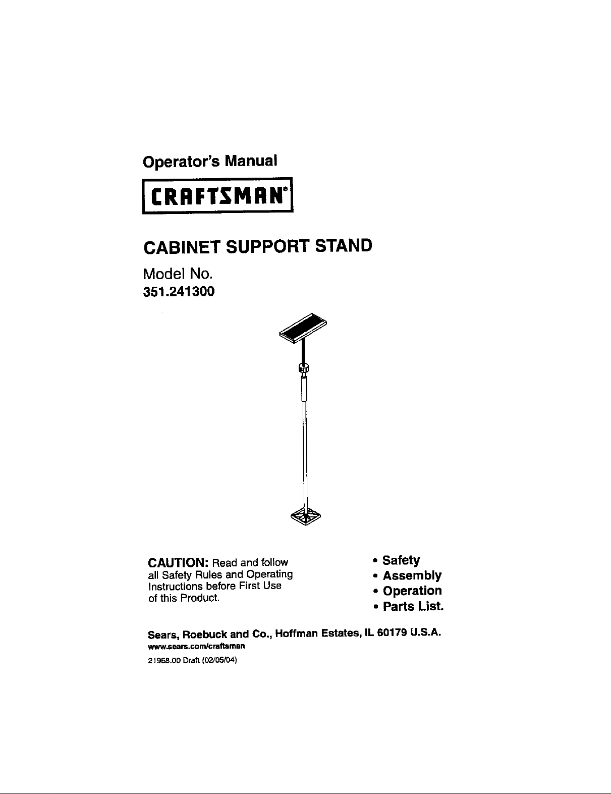
CABINET SUPPORT STAND
Model No.
351.241300
CAUTION: Read and follow
all Safety Rules and Operating
Instructions before First Use
of this Product,
• Safety
• Assembly
• Operation
• Parts List.
Sears, Roebuck and Co., Hoffman Estates, IL 60179 U.S.A.
www.sears.€o m/craftsman
21968,00 Draft (02/05/04)
Warranty....................... 2 Operation ...................... 3
Safety Rules .................... 2 Parts Illustretion and List ........ 4-5
Assembly ..................... 2-3
FULL ONE YEAR WARRANTY
If this product fails due to a defect in material or workmanship within one year from
the date of purchase, Sears willat its option repair or replace it free of charge.
Contact your nearest Sears Service Center (1-800-4-MY-HOME) to arrange for
productrepair, or returnthis product to place of purchase for replacement.
This warranty appliesonly while this productis used in the United States.
This warranty gives you specific legal rightsand you may also have other rights
which vary from state to state.
Sears, Roebuck and Co., Dept. 617WA, Hoffman Estates, IL 60179
• Lockadjustmentsecurely.Adjusting
nutthreads must engage threaded
rod for supportstandto work properly.
• Never overload or over-extend sup-
port stand. Severe personal injury
may result.
Referto Figure 1.
• Check for shipping damage. If dam-
age has occurred, a claim must be
filed with carrier for fastest action.
Check for completeness. Locate all
parts before attempting assembly.
CAUTION: Do not attempt assembly if
parts are missing. Followassembly
instructions.Use parts list to order
replacement parts.
© Sears, Roebuck and Co, 2
• Use good judgement. Do not
attempt to install large, bulky objects
by yourself. Have a second person
help balance the object.
• Only use cabinet support stand on a
level surface.
• Thread base (Key No. 1) unto the
upright(Key No. 3).
• Thread support plate (Key No. 5)
onto the threaded rod (Key No.4).
DESCRIPTION
The Craftsman Cabinet Support Stand,
Model 241300, isa lightweight verstatile
tool,To install cabinets, dry wall ceilings
and many other applications, The
adjustable nut allowspreciseadjustment
to any heightwithinthe specified range,
SPECIFICATIONS
Weight Capacity ............ 400 Ibs
Height Range ............. 50 - 85"
CAUTION: Althoughthe operation of
this tool is simple, the operator must
use this tool carefully.The cabinet sup-
port stand can handle heavy loads, but
if not used correctly,could result in
severe, personal injury.
HEIGHT ADJUSTMENT
Refer to Figure t.
• The height of the support plate is
adjusted by positioningthe threaded
rod (Key No. 5) relative to the
upright(Key No. 3).
Depress buttonon the adjusting nut.
Slide the support plate to near the
desiredsupportheight.
Release button so that adjustingnut
engages thread. Turn adjustingnutto
finely adjustsupport plate to final
height.
Forlarge objects,attach a 2 x 4 to
the supportplate to increase stability.
Other uses of the Cabinet
Support Stand:
Drywall ceilings, duct work, light
fixtures, crown molding,drapery
tracks, beams, headers, rafters,
soffitand decks.
3
 Loading...