

Craftsman 351240950, 351240930 Owner’s Manual
Operator's Manual
CRRFT.TMRN°
4" DRILL PRESS VISE
6" DRILL PRESS VISE
Model No.
351.240930
351.240950
CAUTION:
Read and follow all Safety
_uies and Operating
Instructions before First Use
of this Product.
Sears, Roebuck and Co., Hoffman Estates, IL 60179 U.S.A.
15066.01 Draft (01/16/02)
• Safety
• Assembly
• Operation
• Maintenance
• Parts List
• Espahol
Warranty ...................... 2
Safety Rules ................... 2
Operation ..................... 3
Maintenance ................... 3
Parts Illustration and List ........ 4-5
Espahol ..................... 6-7
FULL ONEYEAR WARRANTY ON CRAFTSMAN 4" AND 6" DRILL PRESS
VISES
If withinone full year from the date of purchase, this Craftsman Drill Press
Vise fails due to a defect in material or workmanship, Seers will repair it free
of charge.
Warranty service is available by simply returning the vise to the nearest Sears
Store or Service Center throughout the United States.
This warranty gives you specific legal rights and you may have other rights
which vary from state to state.
Sears, Roebuck and Co., Dept 817WA, Hoffman Estates, IL 60179
• Understand and obey all safety
instructions supplied with drill press,
mill, or other machines on which
vise is used.
• Clamp vise to work surface in at
least two mounting locations using
mounting grooves provided on base.
• Besure workpiece is clamped
securely between jaws before start-
ing machining operation.
Do not over tighten--vise can devel-
op a large clamping force. Use only
force which is needed.
Do not pound or hammer on work-
piece. This vise is designed to clamp
the workpiece in a desired position
for machining operations only.
2
DESCRIPTION
Craftsman 4" and 6" Drill Press Vises
provide accurate clamping and position-
ing for milling, drilling and other machin-
ing operations. Left and right sides and
back of vise are precision machined
perpendicular to base for precise posi-
tioning. All jaw sliding surfaces and
leadscrew are ground for smooth opera-
tion. Stationary jaw plate is grooved in
cross pattern for clamping round stock
in horizontal and vertical positions.
Grooves on left and right sides of base
are provided to allow for secure mount-
ing of vise to table.
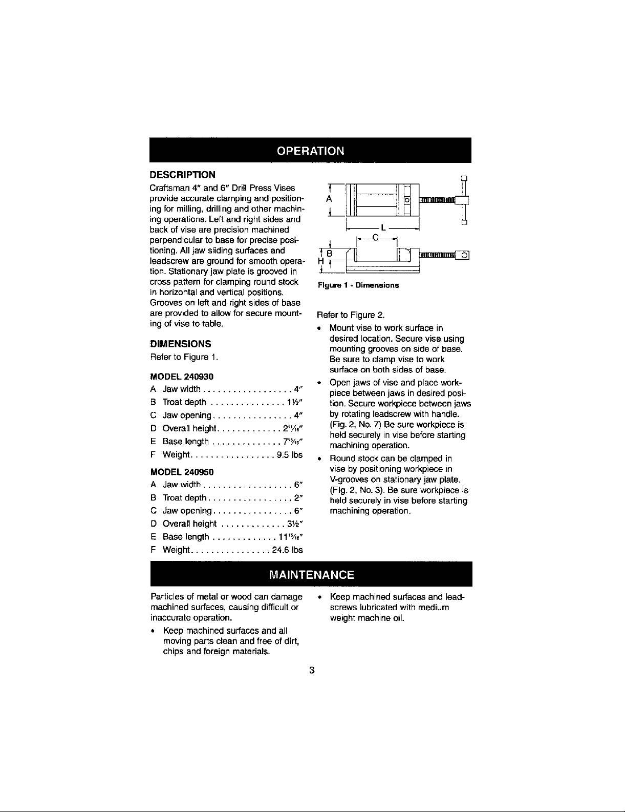
DIMENSIONS
Referto Figure 1.
MODEL 240930
A Jaw width .................. 4"
B Treat depth ............... 1½"
C Jaw opening................ 4"
D Overall height............. 2_¼B"
E Base length .............. 7_5/,6"
F Weight ................. 9.5 Ibs
MODEL 240950
A Jaw width .................. 6"
B Treat depth................. 2"
C Jaw opening................ 6"
D Overallheight ............. 3V2"
E Base length ............. 11_5/;_"
F Weight................ 24.6 Ibs
Figure 1 - Dimensions
Refer to Figure 2.
• Mount vise to work surface in
desired location. Secure vise using
mounting grooves on side of base.
Be sure to clamp vise to work
surface on both sides of base.
• Open jaws of vise and place work-
piece between jaws in desired posi-
tion. Secure workpiece between jaws
by rotating leadscrew with handle.
(Fig. 2, No. 7) Be sure workpiece is
held securely in vise before starting
machining operation.
• Round stock can be clamped in
vise by positioning workpiece in
V-grooves on stationary jaw plate.
(Fig. 2, No. 3). Be sure workpiece is
held securely in vise before starting
machining operation.
Particles of metal or wood can damage
machined surfaces, causing difficult or
inaccurate operation.
• Keep machined surfaces and all
moving parts clean and free of dirt,
chips and foreign materials.
• Keep machined surfaces and lead-
screws lubricated with medium
weight machine oil.
 Loading...