

Craftsman 351240910, 351240890, 351240870 Owner’s Manual
Operator's Manual
£RRFTSMRNo
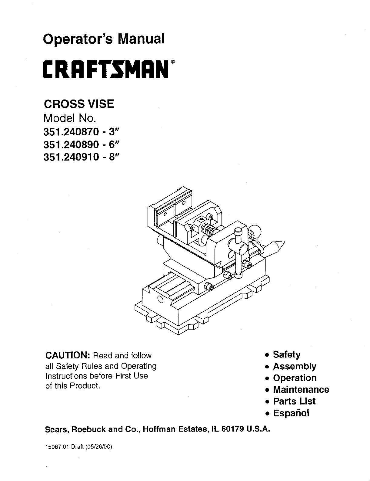
CROSS VISE
Model No.
351.240870 - 3"
351.240890 - 6"
351.240910 - 8"
CAUTION: Read and follow
all Safety Rules and Operating
Instructions before First Use
of this Product.
Sears, Roebuck and Co., Hoffman Estates, IL 60179 U.S.A.
15067.01 Draft (05/26/00)
• Safety
• Assembly
• Operation
• Maintenance
• Parts List
• EspaSol
Warranty ....................................... 2
Safety Ru_es .................................... 2
Assembly ...................................... 2
Operation ...................................... 2
Maintenance ........................... ......... 3
Parts Illustration and List ......................... 4-5
Espa6ol ...................................... 6-7
FULL ONE YEAR WARRANTY ON CRAFTSMAN
CROSS VISES
If within one full year from the date of purchase, this
Craftsman Cross Vise fails due to a defect in material or
workmanship, Sears will repair it free of charge.
Warranty service is available by simply returning the Cross
Vise to the nearest Sears Store or Service Center throughout
the United States,
This warranty gives you specific legal rights and you may
have other rights which vary from state to state.
Beam, Roebuck and Co., Dept 817WA, Hoffman Estates, IL
60179
• Understand and obey all safety instructions supplied with
drill press, mill, or other machines on which vise is used.
• Bolt or clamp vise to work surface in at least two mounting
locations using mounting flanges provided on base.
• Be sure workpiece is clamped securely between jaws
before starting machining operation,
• Do not over tighten---vise can develop a large clamping
force, Use only force which is needed.
• Do not pound or hammer on workpiece. This vise is
designed to clamp the workplace in a desired position for
machining operations only.
MODEL 240870, 3n VISE
Refer to Figure 1.
* Mount crank handles (Fig. 1, No. 12) to longitudinal and
cross feed screws (Fig. 1, Nos. 8and 9) using acorn nuts
(Fig. 1, No. 13).
• This vise is shipped with a protective coating.This coating
should be removed before operation. Remove protective
coating with penetrating oil.
MODELS 240890 AND 240910, 6" AND 8" VISES
Refer to Figure 1.
• Thread movable jaw Isadscrew (Fig. 1, No. 14) through end
of body (Fig. 1, No. 16) and into hole in movable jaw (Fig. 1,
No. 18).
• Secure with dog point set screw (Fig. 1, No, 19)
• Mount crank handles (Fig. 1, No. 12) to longitudinal and
cross feed screws (Fig. 1, Nee. 8 and 9) using acorn nuts
(Fig. 1, No. 13),
• This vise is shipped with a protective coating. This coating
should be removed before operation. Remove protective
coating with penetrating oil
DESCRIPTION
Cross Vises travel on two separate axes---longitudinal and
cross, to permit accurate positioning of workplace. Body, sad-
dle, base and jaws are made of high strength cast iron, Vise
leadscrew, longitudinal and cross feed screws are precision
ground carbon steel.
• Mount vise to work surface in desired location by secudng at
least two mounting flanges located on base (Fig, 1, No, 1).
• Move saddle (Fig, 1, No. 3) by rotating longitudinal crank
handle (Fig. 1, No. 12).lqghtan center set screw (Fig. 1,
No.6) to secure position.
• Move body (Fig. 1, No. 16) to desired position by rotating
crossroad crank handle (Fig. 1, No. 12). Tighten center set
screw (Pig. 1, No. 6) to secure position.
• Open jaws of vise. Place workpiece between jaws in
desired position. Rotate movable jaw leadserew (Fig. 1, No.
14) to secure workpiece between jaws. Be sure workpiece
is secure in vise before starting machining operation.
SPECIFICATIONS
Longitudinal travel (left to right) .............. 5" (240870)
..................................... 8" (240890)
..................................... 8_ (240910)
Cross travel (front to back) ................. 5" (240870)
..................................... 6" (240890)
..................................... 8" (240910)
Jaw Width .............................. 3" (240870)
..................................... 6_ (240890)
..................................... 8" (240910)
Maximum Jaw Opening ................... 3" (240870)
..................................... 6"(240890)
..................................... 6"(240910)
Value el One Divimon ................ 0.0039"(240870)
................................. 0.0039 _ (240890)
................................. 0.0039"(240910)
Cross Travel per One Revolution ........ 0.1181" (240870)
................................. 0.1575" (240890)
................................. 0.1575" (240910)
Longitudinal Travel per One Revolution ... 0.1181" (240870)
................................. 0.1575"(240890)
................................. 0.1575" (240910)
2
Particles of metal or wood can damage machined surfaces,
causing difficult or inaccurate operation.
,* Keep machined surfaces a_ndall moving parts clean and
free of dirt, chips and foreign materials.
• Keep machined surfaces and.leadscrews lubricated with
medium weight machine oil
GIB AD3USTMENT
Refer to Figure 1.
• Adjust gibs (Fig. 1, No.4) by tightening the set screws (Fig.
1, Nos. 6 and 23) at each end of the g[bs.
• Adjust the screws until a slight drag is felt when rotating the
crank handles (Fig. 1, No. 12). Secure screws by tightening
nuts (Fig. 1, No. 5).
 Loading...