

Craftsman 351233731 Owner’s Manual
SAVE THiS MANUAL
FOR
FUTURE REFERENCE
MODEL NO.
351.23373!
CAUTION:
READ ALL
INSTRUCTIONS
CAREFU LLY!
12 1/2" PLANER
o safety instructions
o operating instructions
o replacement parts
Sold by SEARS: ROEBUCK AND CO.: Chicago: RL60684 U.S.A. ©
_art No. 4290.01 October 1991

FULL ONE YEAR WARRANTY ON SEARS/CRAFTSMAN 12 1/2" Thickness Planer
if within one full yeer from the date of purchase, this Sears Craftsmen 12 1/2" Thickness
Planer fails due to a defect in material or workmanship, Sears will repair it, free of charge.
WARRANTY SERVICE IS AVAILABLE BY SIMPLY CONTACTING THE NEAREST SEARS STORE
OR SERVICE CENTER THROUGHOUT THE UNITED STATES.
This warranty gives you specific lega_ rights, and you may have other rights which vary
from state to state.
SEARS, ROEBUCK AND CO., DEPT.698/731A SEARS TOWER, CHICAGO, IL 60684
GENERAL SAFETY INSTRUCTIONS FOR POWER TOOLS
BEFORE ANY WORK IS DONE, READ THE CAU=
TIONS LISTED BELOW CAREFULLY. WORKING
SAFELY PREVENTS ACCIDENTS.
OPERATOR SHOULD BE PREPARED FOR THE JOB
a. Wear proper apparel Do not wear loose clothing,
gloves, neckties, rings, bracelets or other jewelry
which may get caught in moving parts of the
machine.
b. Wear protective hair coveringto contain long hair.
c. Wear safety shoeswith non-slip soles.
d. Wear safety glasses. Everyday glasses have
only impact resistant lenses. They are not safety
glasses.
e. Wear face mask or dust mask if cutting operation
is dusty.
f. Be alert and think dearly. Never operate power
tools when tired, intoxicated or when taking
medications that cause drowsiness.
WORK AREA SHOULD BE READY FOR THE JOB:
a. Keep work area dean. Cluttered work areas and
workbenches invite accidents.
b. Do not use power tools in dangerous environ-
ments. Do not use power tools indamp or wet loca-
tions. Do not expose power tools to rain.
c. Work area should be properly Hghted.
d. The proper electrical outlet should be available
for the tool, A three-prong plug should be plugged
directly into a properly grounded three-prong
receptacle.
e. Extension cords shouBd have a ground prong and
the three wires of the extension cord should be the
correct gauge.
f. Keep visitors a safe distance from work area.
g. Keep chiHdren out of workplace. Make workshop
children-proof. Use padlocks, master switches and
remove starter keys to prevent any unintentional
use of power tools.
TOOL SHOULD BE MAINTAKNED:
a. Always unplug power tool prior to inspection.
b. Consult the owner's manualfor specific maintain-
ing and adjusting procedures.
c. Keep machine lubricated.
d. Use sharp bKadesand keepthetool clean for safest
operation.
e. Remove adjusting keys and wrenches. Form
habit of checking to see that keys and adjusting
wrenches are removed from tool before turning on.
f. Keep aH guards in place and inworking order.
g. Keep all parts in working order. Check to deter-
mine that the guard or other parts will operate
properly and perform their intended function.
h. Check for damaged parts. Check for alignment of
moving parts, binding of moving parts, breakage of
parts, mounting and any other condition that may
affect a tool's operation.
i. A guard or other part that is damaged should be
properly repaired or replaced. Do not perform
makeshift repairs (use the parts list provided with
owner's manual to order replacement parts).
OPERATOR SHOULD KNOW HOW TO USE TOOL:
a. Use the right tooa for the job. Do not force a tool
or attachment to do a job for which it was not
designed.
b. Disconnect tool when changing accessories,
such as blades, bits, cutters and the like.
c. Avoid accidental start-up. Make sure that the
machine is in the "off" position before plugging in.
d. Do not force a tool. _twill work most efficiently
at the rate for which it was designed.
e. Use recommended accessories. Consult the
owner's manual for recommended accessories.
The use of improper accessories may cause risk of
injury to persons,
f. Handle the workpiece correctly. Use push sticks
or push blocks when required; protect hands from
possible injury.
g. Direction of feed. Feed work into a blade or cutter
against direction of rotation of the blade or cutter.
h. Turn the machine off if it jams. A blade jams when
digs too deeply into the work (the motor force
keeps it stuck in the work).
i. Never leave a tooJ running unattended. Turn the
power off and do not leave too! until it comes to a
complete stop:
j. Do not overreach. Keep proper footing and
balance.
k. Never stand on tool. Serious injury could occur if
the tool istipped or if the cutting too! is unintention-
ally contacted.
I. Keep hands away from moving parts and cutting
surfaces.
m. Know your power tool. Learn its operation, ap-
plication and specific limitations.

CONTENTS
Warranty ................................ 2
General Safety instructions
for Power Tools ....................... 2
Safety instructions for Planer ................ 3
Motor Specifications
and Electrical Requirements ............ 4
Electrical Connections ..................... 5
Unpacking and Checking Contents ........... 5
Assembly ................................ 5
WARNING LABELS
The 12 1/2" thickness planer has been marked with Thesawarning labels are placed in specific locations so
warning labels that need to be observed for safe opera- they are visible to the operator when starting and
tion. The operator should be aware of the location and operating the tool.
contents of these labels.
Operation ................................ 6
Maintenance ............................. 8
Trouble Shooting .......................... 9
Parts Illustration for Base .................. 10
Parts List for Base ........................ 11
Parts IHustra_ion for Roller Case ............. 12
Parts List for Roller Case .................. 13
Parts Illustration for Motor ................. 14
Parts List for Motor ....................... 15
LABEL ON FRONT OF UNIT
WARNING;
FOR SAFE OPERATION SEE OWNER'S MANUAL
Keep hands away during operation.
Allow the automatic feed to function properly.
Do not push or pull workpiece through machine.
Cutterhead must be at a complete stop before
freeing the workplace or making any adjustments.
Do not cut deeper than 1/16".
Wear eye protection.
LABEL ON SIDE OF UNIT
WARNING:
Always use planer with cutterhead guard.
Cutterhead must be at a complete stop
before freeing the workpiece or making
any adjustments.
Use only identical replacement parts,
SAFETY INSTRUCTIONS FOR 1
WARNING: DO NOT ATTEMPT TO OPERATE
PLANER UNTIL IT IS COMPLETELY ASSEMBLED
ACCORDING TO INSTRUCTIONS.
1, KNOW GENERAL POWER TOOL SAFETY. Make
sure all precautions are understood and provided
for (see page 2),
2. SECURE ALL FASTENERS. Frequently check that
nuts and bolts are tight and have not vibrated loose.
3, FOLLOW OPERATION INSTRUCTIONS. Operate
the planer as described in the manual.
4. DO NOT FORCE THE CUT. Slowing or stalling the
motor will overheat it. Allow the automatic feed to
function properly.
5. SUPPORT WORKPIECE. Do not allow the board
to hang from the planer. Use support rollers,
& USE QUALITY LUMBER. Blades last longer and
cuts go smoother on good wood.
7. DO NOT PLANE UNDERSIZED WOOD. Boards
which are too thin or too short could split while
being planed.
8. TAKE PRECAUTIONS AGAINST KICKBACK. Do
not permit anyone to stand or cross inline with the
cutterhead's rotation. A kickback or thrown debris
will travel in this direction.
9. KEEP PLANER MAINTAINED. Follow main-
tenance instructions (see page 8).
LABEL ON CUTTERHEAD GUARD
WARNING
® TO REDUCE RISK OF INJURY,
ATTACH THE SAFETY COVER BEFORE
OPERATING.
2 1/2" THICKNESS PLANER
10. DISCONNECT POWER. Turn switch "OFF" and
disconnect power whenever planer is not in use.
CAUTION: DO NOT ALLOW FAMILIARITY (GAINED
FROM FREQUENT USE OF YOUR PLANER) TO BE-
COME COMMON PLACE. ALWAYS REMEMBER THAT
A CARELESS FRACTION OF A SECOND IS SUFF!-
CIENT TO INFLICT SEVERE INJURY.
The operation of any power tool can result in foreign ob-
jects being thrown into the eyes, which can result in
severe eye damage.
Always wear safety goggles complying with ANSI Z87.1
(shown on package) before commencing power tool
operation. Safety goggles are available at Sears retail or
catalog stores.
"THINK SAFETY: Safety is a combination of operator
common sense and alertness at all times when the
planer is being used.
MOTOR SPECIFICATIONS & ELECTRICAL REQUIREMENTS
MOTOR
The 12 1/2"thickness planer is supplied with a motor and
with the wiring installed.
The 120 Volt AC universal motor has the following
specifications:
Max. Developed Horsepower ................... 2
Voltage ................................... 120
Amperes .................................. 14
Hertz ..................................... 60
Phase .................................. Single
RPM .................................... 8000
POWER SOURCE
1. The motor is designed for operation on the voltage
and frequency specified above.
2. Normal loads will be handled safely on voltages not
more than 10% above or below the specified volt-
age.
3. Running the unit on voltages which are not within
the range may cause overheating and motor burn-
out.
4. Heaw loads require the voltage at motor terminals
be not less than the voltage specified.
GROUNDING INSTRUCTIONS
This tool is equipped with a three-conductor cord and
ground type plug which has a grounding prong, ap-
proved by Underwriters Laboratories and the Canadian
Standards Association.
Do not remove or alter the grounding prong in any man-
ner.
In the event of a malfunction or breakdown grounding
prov des a path of least resistance for electrical current
to reduce the risk of electrical shock.
The plug must be plugged into a matching outlet that is
properly installed and grounded in accordance with all
local codes and ordinances.
Do not modify the plug provided. If itwill not fit inthe out-
let, have the proper outlet installed by a qualified
electrician.
Improper connection of the equipment-grounding
conductor can result in a risk of e_ectrical shock.
The conductor with insulation having a green outer sur-
face is the equipment-grounding conductor.
If repair or replacement of the electrical cord or plug is
necessary, make sure the equipment-grounding con-
ductor is not connected to a line terminal.
Check with a qualified electrician or service person-
nel if the grounding instructions are not understood,
or if in doubt as to whether the tool is properly
grounded.
The tool has a three-prong plug, such as the one il-
lustrated.
This tool is intended for use on a circuit having anominal
rating less than 150 volts which has an outlet that looks
like the outlet illustrated.
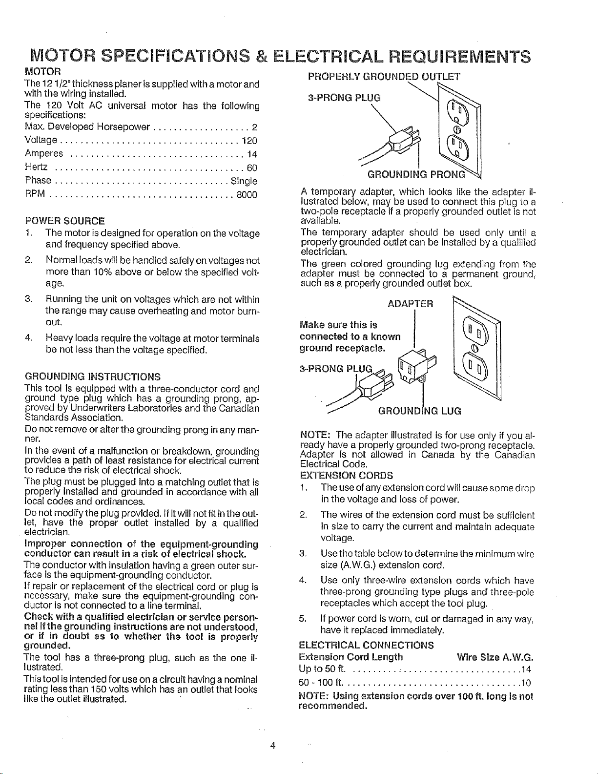
PROPERLY GROUNDED OUTLET
3-PRONG PLUG_I __ 1
GROUNDING PRONG
A temporary adapter, which looks like the adapter il-
lustrated below, may be used to connect this plug to a
two-pole receptacle if a properly grounded outlet is not
available.
The temporary adapter should be used only until a
properly grounded outlet can be installed by a qualified
electrician.
The green colored grounding lug extending from the
adapter must be connected to a permanent ground,
such as a properly grounded outlet box.
Make sure this is I
connected to a known
ADAPTERI __
3-PRON__gr°undreceptacle. I_
/ GROUNDING LUG
NOTE: The adapter illustrated is for use only if you al-
ready have a properly grounded two-prong receptacle.
Adapter is not allowed in Canada by the Canadian
Electrical Code.
EXTENSION CORDS
1. The use of any extension cord will cause some drop
in the voltage and loss of power.
2. The wires of the extension cord must be sufficient
in size to carry the current and maintain adequate
voltage.
3. Use the table below to determine the minimum wire
size (A.W.G.) extension cord.
4. Use only three-wire extension cords which have
three-prong grounding type plugs and three-pole
receptacles which accept the tool plug.
5. If power cord is worn, cut or damaged in any way,
have it replaced immediately.
ELECTRICAL CONNECTIONS
Extension Cord Length Wire Size A,W.G.
Upto 50 ft.................................. 14
50 - 100 ff................................... 10
NOTE: Using extension cords over 100 ft. long is not
recommended,
ELECTRmCAL CONNECTIONS
WARNING: MAKE SURE THE UNIT IS "OFF" AND
DISCONNECTED FROM THE POWER SOURCE
BEFORE INSPECTING ANY WIRING.
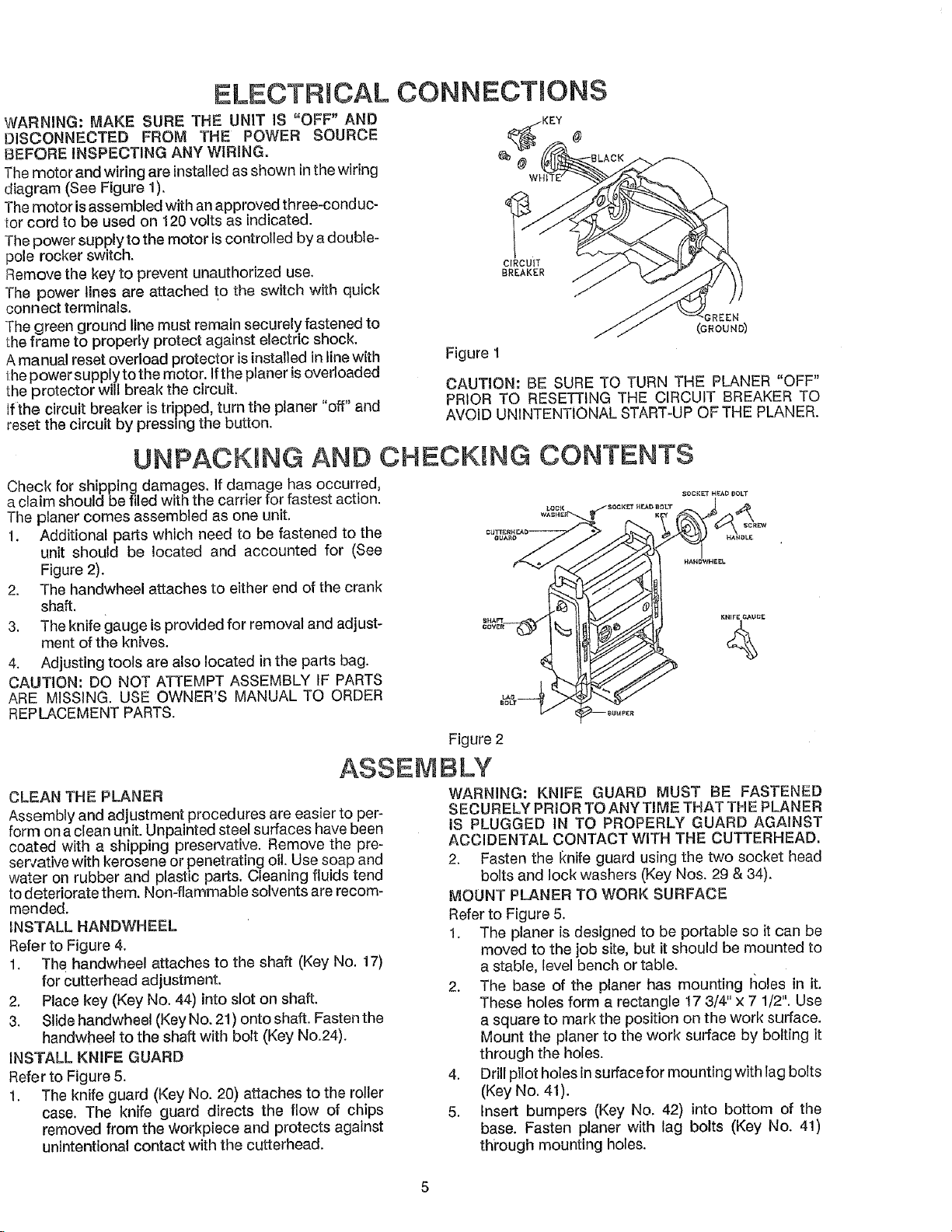
Themotor and wiring are installed as shown inthe wiring
diagram (See Figure 1).
Themotor isassembled with an approved three-conduc-
tor cord to be used on 120 volts as indicated.
The power supply to the motor iscontrolled by a double-
pole rocker switch.
Remove the key to prevent unauthorized use.
The power lines are attached to the switch with quick
connect terminals.
The green ground line must remain securely fastened to
the frame to properly protect against electric shock.
A manual reset overload protector isinstalled in linewith
the power supply to the motor. If the planer isoverloaded
the protector will break the circuit.
tf the circuit breaker istripped, turn the planer "off" and
reset the circuit by pressing the button.
CIRCUIT
BREAKER
Figure 1
CAUTION: BE SURE TO TURN THE PLANER "OFF"
PRIOR TO RESEN'ING THE CIRCUIT BREAKER TO
AVOID UNINTENTIONAL START-UP OF THE PLANER.
@
REEN
(GROUND)
UNPACKING AND CHECKING CONTENTS
Check for shipping damages. If damage has occurred,
a claim should be filed with the carrier for fastest action. _oo,,_...... _T
The planer comes assembled as one unit.
1. Additional parts which need to be fastened to the
unit should be located and accounted for (See
Figure 2),
2. The handwheel attaches to either end of the crank
shaft.
3. The knife gauge isprovided for removal and adjust- *.........!
ment of the knives. _
4. Adjusting tools are also !ocated in the parts bag.
CAUTION: DO NOT ATTEMPT ASSEMBLY IF PARTS
ARE MISSING. USE OWNER'S MANUAL TO ORDER
REPLACEMENT PARTS.
ASSEMBLY
CLEAN THE PLANER
Assembly and adjustment procedures are easier to per-
form on aclean unit. Unpainted steel surfaces have been
coated with a shipping preservative. Remove the pre-
ser,,ative with kerosene or penetrating oil. Use soap and
water on ruboer and plastic parts. Cleaning fluids tend
to deteriorate them. Non-flammable solvents are recom-
mended.
INSTALL HANDWHEEL
Refer to Figure 4.
1. The handwheel attaches to the shaft (Key No. 17)
for cutterhead adjustment.
2. Place key (Key No. 44) into slot on shaft.
3. Slide handwheel (Key No. 21) onto shaft. Fasten the
handwheel to the shaft with bolt (Key N0.24).
INSTALL KNIFE GUARD
Refer to Figure 5.
1. The knife guard (Key No. 20) attaches to the roller
case. The knife guard directs the flow of chips
removed from the Workpiece and protects against
unintentional contact with the cutterhead.
Figure 2
WARNING: KNIFE GUARD MUST BE FASTENED
SECURELY PRIOR TO ANY TIME THAT THE PLANER
IS PLUGGED IN TO PROPERLY GUARD AGAINST
ACCIDENTAL CONTACT WITH THE CUTTERHEAD,
2. Fasten the I_nife guard using the two socket head
bolts and lock washers (Key Nos, 29 & 34).
MOUNT PLANER TO WORK SURFACE
Refer to Figure 5.
1. The planer is designed to be portable so it can be
moved to the job site, but it should be mounted to
a stable, level bench or table.
2. The base of the planer has mounting I_oles in it.
These holes form a rectangle 17 3/4" x 7 1/2". Use
a square to mark the position on the work surface.
Mount the planer to the work surface by bolting it
through the holes.
4. Drill pilot holes in suffacefor mounting with lag bolts
(Key No. 41).
5. Insert bumpers (Key No. 42) into bottom of the
base. Fasten planer with lag bolts (Key No. 41)
thi'ough mounting holes.
 Loading...