

Craftsman 351231060 Owner’s Manual
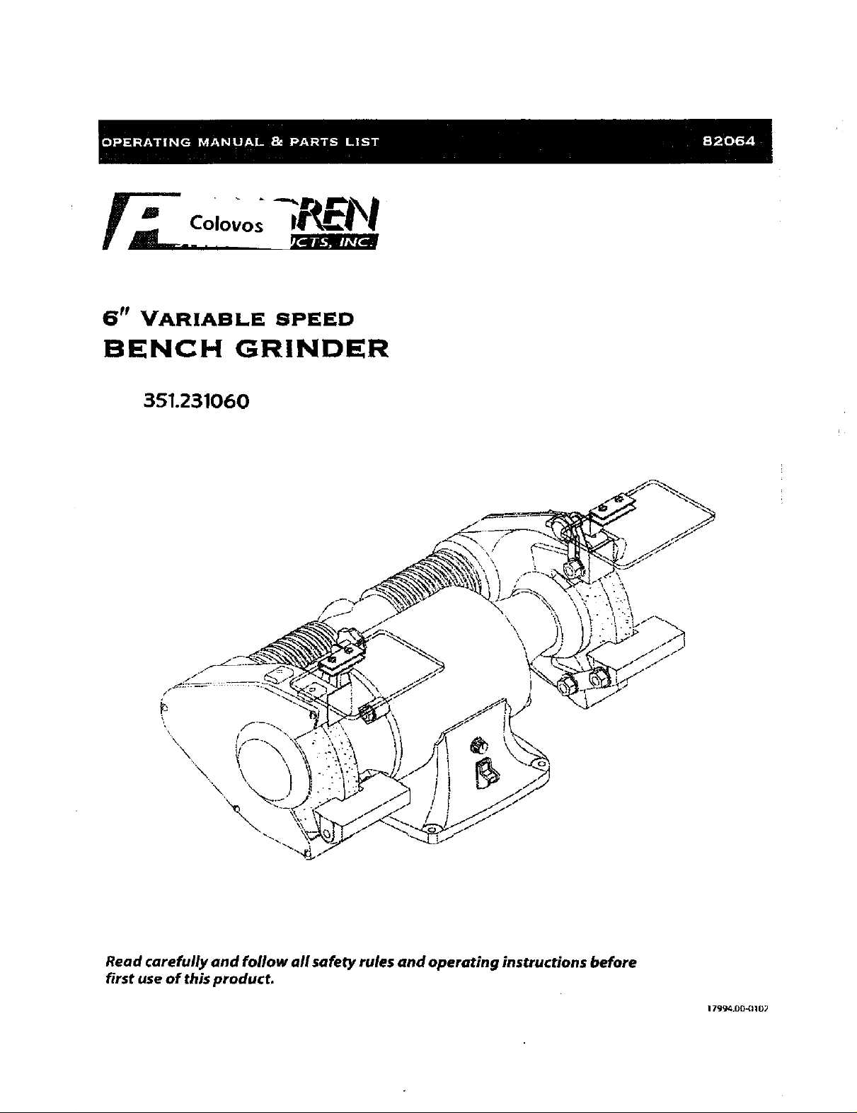
6 r_ VARIABLE SPEED
BENCH GRINDER
351.231060
Read carefully and foflow all safety rules and operating instructions before
first use of this product.
179_4.00_110_
Palmgren Operating Manual & Parts Ust 82064
• Extension cords should have a grounding prong and the three
wires of the extension cord should be of the correct gauge.
This Palmgren Bench Grinder is equipped wiSh a totally endosed
ball bearing motor. Armature assembly is dynamically balanced for
smooth operation. Motor housing is compact so long pieces of
work can press against both wheels without touching the motor
frame, Grinder operates at 3450 rpm for gdnding and also at 2000-
3300 rpm for sharpening. Removable wheel guards allow for easy
changing of wheels.Two-way tool rests are adjustable for wheel
wear and angle grinding.Grinder comes complete with spark
guards, safety eyeshields and dust collection hose.
Check for shipping damage. If damage has occurred, a claim must
be filed with the carrier immediately. Check for co¢_pleteness.
Immediately report missing parts to dealer.
SPECIFICATIONS
Horsepower ................................................. _1_
Voltage .................................................... 120
Amperes ................................................... 3,5
Hertz ...................................................... .60
Phase ................................................... Single
RPM ........................................... 20OQ-3300, 3450
Rotation (viewed from left side) ....................... .L"_ockw|se
Wheel diameter ............................................. .6"
Wheel bore ................................................. Yz"
WARNING: For your own safety, read operating instructions man-
ual before operating tool.
BE PREPARED FOR JOB
• Wear proper apparel Do not wear foose dothlng, gloves, neck-
ties, rings, bracelets or other jewelry which may get caught in
moving parts of machine.
• Wear protective hair covering to contain fong hair.
• Wear sa|ety shoes with non-slip soles.
• Wear _afety glasses complying with United States ANSI Z87.1.
Everyday glasses have only impact resistant lenses.They are
NOT safety glasses.
• Wear face mask or dust mask if operation is dust7.
Be alert and think cleady. Never operate power tools when
tired, intoxicated or when taking medications that cause
drowsiness.
PREPARE WORK AREA FOR JOB
Keep work area dean. Cluttered work areas and work benches
invite accidents.
Do not use power tools in dangerous environments.Do not use
power tools in damp or wet locations. Do not expose power
tools to rain.
• Work area should be proporly lighted.
• Proper efectdcal plug should be plugged directly into propody
grounded, three-prong receptacfe.
Keep v_sitors at a safe distance from work area.
Keep children out of the wot_ace. Make workshop chitdprooE
Use padlocks, master switches or remove switch keys to pm
vent any unintentiona( use of power tobls.
TOOL SHOULD BE MAINTAINED
• Always unplug tool prior to inspection.
• Consult manual for specificmalntalning and adjusting proce-
dures.
Keep tool clean for safest operation
• Remove adjusting tools. Form habit of checking to see that
adjusting tools are removed before turning machine on
• Keep air parts in working order.Check to determine that the
guard or other parts w_IIoperate pl"opedy and pe_orm their
intended function.
• Check for damaged parts. Check for alignment of moving parts,
binding of moving parts, breakage of parts, mounting and any
other condition that may affect a todi's operation.
• A guard or other part that is damaged should be properly
repaired or replaced, Do not perform makeshift repairs. (Use
the parts list to order replacement parts.)
KNOW HOW TO USE TOOL
• Use dght too_ for )o_ Do not force tobl or attachment to do a
job for which it was not designed.
* Disconnect tool from power when changing accessories such
as grinding wheels, buffing wheels and the like.
• Avoid accidental start-up.Make sure that the switch is in the off
position before plugging in.
• Do not force tool, It will work most effic]enBy at the rate for
which it was designed.
• Keep hands away from moving parts and grinding surfaces.
• Never reave a tool running unattended.Turn the power _ff and
do not leave tool unt(I it comes to a complete stop.
• Do not overreadm Keep proper footing and balance.
• Never stand on tool.Serious injury could occur if tool is tipped
ovel_.
• Know your tool. Learn the todi's operation, application and spe-
cific limifaEons.
• Use recommended accessories.Understand and obey all safety
instructions supplied with accessories,The useof improper
accessoriesmay causeriskof injury topersons.
• Do not over tighten wheel nut. Replacecracked wheel immedi.
arely.Useonlyflanges suppliedwith the gdnder.
• Adjust distance between wheel and tool rest to maintain '/,," or
lessgap,
• Handlesheworkpiececorrectly.Wheneverpossible, usetool
restto support workpiece during g_inding operation.Turn tool
off if it jams.
• Alwaysuseguards and eyeshfelds,
• Qean grinding dust from beneath tool fTequentJy.
2
9almgren Operating Manua_ & Parts Us,t 82964
EYESHIELD ASSEMBLY
• Remove %" hex nut (D_ and %" fiat washer (C) from '/,- 16 x l ¼_
Parts to be fastened to the unitshould be located and accounted
for (See List and Figure 1).
IMPORTANT: Do not attempt assembly if parts are missing. Use
thls manual to order replacement parts.
A '/,_ 18 x 1%" Carriage bolt, 2 each
B Tool rest bracket, 2 each
C *%" Rat washer, 4 each
D *'/."-16 Hex nut,4each
E Tool rest. 2each
F V_r,"Flat washer, 2 each
G s/_"- 18, Hex nut, 2 each
H *_/rl 6 x 1¼" Hex bolt, 4 each
I Knob, 2 each
J Spark guard. 2each
K Eyeshield, 2 each
L Lower eyeshieid bracket,2 each
M Upper eyeshield bracket, 2 each (left and right)
N #10-24 x 'J_"_an head scTew, 4 each
O % 20 x 'A" Flange screw, 2 each
P '//' Flat washer, 2 eadn
Q Spacer. 2 each
R Dust collector hose (not shown)
NOTE; Parts marked with an asterisk (*) are mounted to the
grinder at the factory.
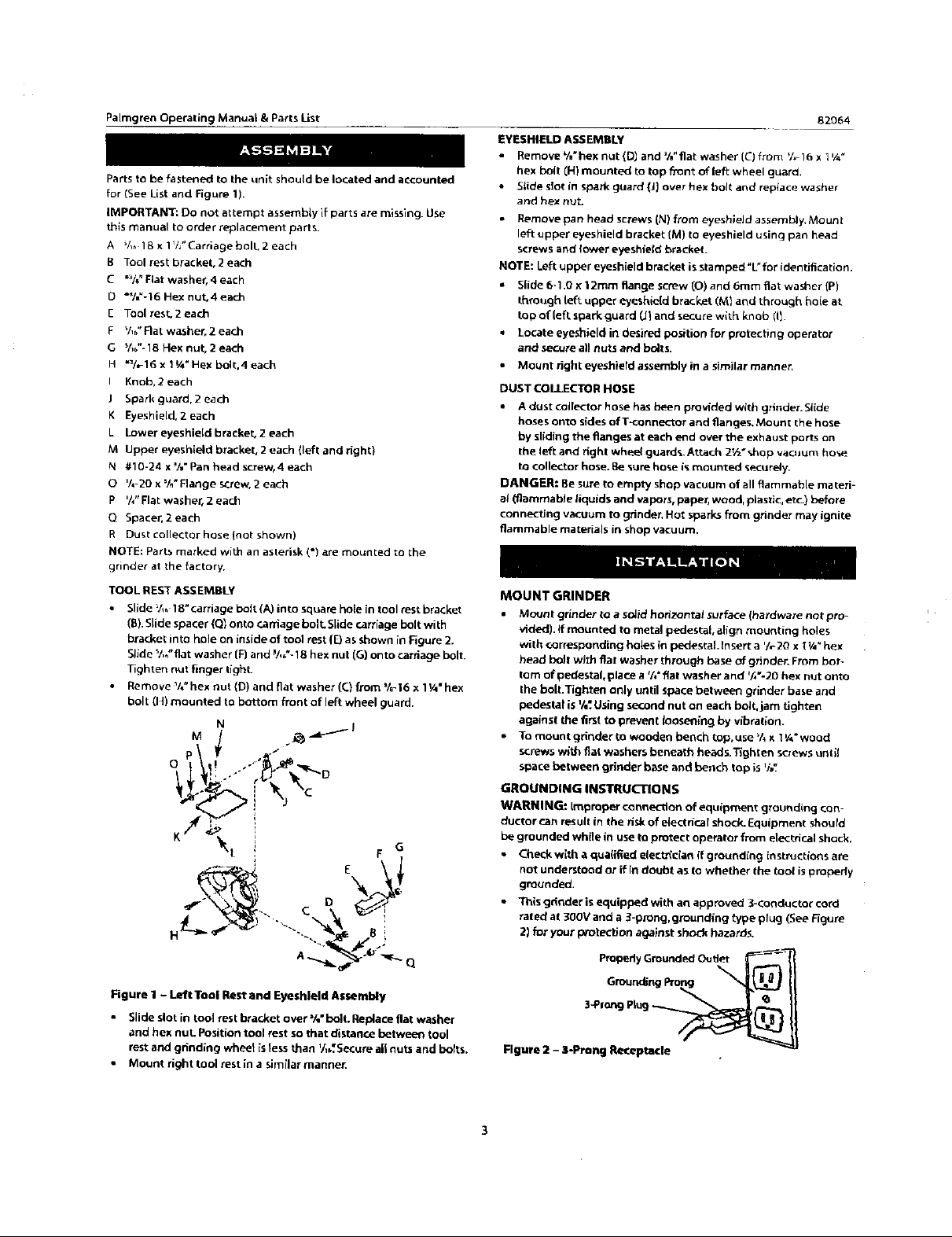
TOOL REST ASSEMBLY
• Slide V,_ 18" carriage bolt (A) into square hole in tool rest bracket
(E). Slide spacer (Q] onto r.arriage boll SLide can'iage bolt with
bt_et into hole on inside of t`ool rest (_ as SfnOW_in _gure 2.
SEde %_"flat washer [F) and _/,,"-18 hex nut (G) onto caniage bolt.
Tighten nut finger tighL
• Remove%"hexnut(D)andflatwasher(C}from%_16x1¼"hex
bolt (HI mounted to bottom front of left wheel guard.
hex bolt (H) mounted to top fi'ont of left wheel guard.
• Slide slot in spark guard (J) over hex holt and reptace washer
and hex nut.
• Remove pan head screws (N) from eyeshieJd assembly, Mount
left upper eyes hield bracket (M) to eyeshield using pan head
screws and lower eyeshield bracket.
NOTE: Left upper eyesh[eld bracket is stamped "L" for identification.
• Slide 6-1.0 x t 2mm flange screw (0) and 6ram flat waslqer (P)
through left upper eyeshie[d bracket (M} and through hole at.
top of(eftspark guard (J_and secure with knob (11.
Locate eyeshield in desired position for protecting operator
and secure all nuts and bolts.
• Mount right eyeshiefd assembly in a similar manner,
DUST COLLECTOR HOSE
• A dust collector hose has been provided with grinder. Slide
hoses onto sides ofT-connector and flanges. Mount the hose
by sliding the flanges at each end over the exhaust ports on
the left and right whee( guard% Attach 2t_ * shop vacuum hose
to colle_r hose. Be _ure hose is mounted securely,
DANGER: Be sure to empty shop vacuum of all flammable ma teri-
a_ (flammable _iquids and vapors, paper, wood, plastic, etc.) before
connecting vacuum to grinder, Hot sparks from grinder may ignite
flammable materials in shop vacuum.
MOUNT GRINDER
• Mount grinder to a soJidhorizontal surface(hardware not pro-
vided), if mounted to metal pede_;tal,align mounting holes
with corresponding bok==sin pedestal tnsett a _h-2Ox t¼"hex
head bolt with fiat washer through base ofgrinder. From bot-
tom ofpedestal,placea %"fiatwasherand %'-20hex nutonto
thebolt.Tightenonlyuntilspacebetween grinderbaseand
pedestalisV,_.U_ingsecondnuton eachbolt,jam tighten
againstthefirsttopreventlooseningby vib_afion.
• To mount grindertowooden bench top.use_/_x 1¼" wood
screw_w_thflat washersbeneath head_.Tighten screws unlit
spacebetween grinderbaseand bench topis'/,_
GROUNDING INSTRUCTIONS
WARNING: Improper connection of equipment grounding con-
ductor can result in the risk of electrical shock_ Equipment should
be grounded while in use to protect operator from electrical shock,
• Check with a qua(ified eleet_c{a_ {f grounding instructions are
not understood or if in doubt as to whether the tool is propedy
grounded,
• This gdnder is equipped with an approved 3-conductor cord
rated' at 300V and a 3-prong, grounding _ype plug (See Figure
2) for your protection against shock hazards,
Figure I - Left Tool Rest and Eyeshleld Assembly
• Slide slot in too] rest bracket over %" bolt. Replace flat washer
and hex nut Position tool rest so that distanr.e between tool
rest and grinding whee_ )s less _an '/,b'.Secure a|t nuts and bolts.
• Mount right tool rest in a similar manner.
3*Pf_'_J P_ug_
Rgu_e 11- 3-Pro_ Re_eptatle
 Loading...