

Craftsman 351228051, 351228031 Owner’s Manual

Operator's Manual
®
10" and 12"
LEFT-TILTING ARBOR SAW
Model No.
351.228051
351.228031
CAUTION:
Read and follow all Safety
Rules and Operating
Instructions before First
Use of this Product. Keep
this Manual with Tool.
• Safety
• Assembly
• Operation
• Maintenance
• Parts List
• Espa5ol
Sears Brands Management Corporation, Hoffman Estates, IL 60179 U.S.A.
www.craftsman.com
32243.00 Draft (07/30/10)
Warranty ......................................... 2
Safety Rules .................................... 2-5
Unpacking ...................................... 5-6
Assembly ...................................... 6-8
Installation ..................................... 8-10
Operation .................................... 10-14
Maintenance .................................... 14
Troubleshooting ............................... 15-16
Parts Illustration and List ........................ 17-27
Espa_ol ...................................... 30-47
CRAFTSMAN PROFESSIONAL ONE YEAR FULL
WARRANTY
FOR ONE YEAR from the date of purchase, this product is
warranted against any defects in material or workmanship.
Defective product will receive free repair or free replacement
if repair is unavailable.
For warranty coverage details to obtain repair or replace-
ment, visit the web site: www.craftsman.com
This warranty does not cover blades, which is an expendable
part that can wear out from normal use within the warranty
period.
This warranty gives you specific legal rights and you may also
have other rights which vary from state to state.
Sears Brands Management Corporation, Hoffman Estates, IL
60179
WARNING: For your own safety, read all of the instructions
and precautions before operating tool.
PROPOSITION 65 WARNING: Some dust created by
using power tools contain chemicals known to the state of
California to cause cancer, birth defects or other reproductive
harm.
Some examples of these chemicals are:
• Lead from lead-based paints.
• Crystalline silica from bricks and cement and other
masonry products.
• Arsenic and chromium from chemically-treated lumber.
Your risk from these exposures vary, depending on how often
you do this type of work. To reduce your exposure to these
chemicals: work in a well ventilated area and work with
approved safety equipment. Always wear OSHA/NIOSH
approved, properly fitting face mask or respirator when
using such tools.
CAUTION: Always follow proper operating procedures as
defined in this manual i even if you are familiar with use of
this or similar tools. Remember that being careless for even
a fraction of a second can result in severe personal injury.
BE PREPARED FOR JOB
• Wear proper apparel. Do not wear loose clothing, gloves,
neckties, rings, bracelets or other jewelry which may
get caught in moving parts of machine.
Sears Brands Management Corporation
• Wear protective hair covering to contain long hair.
• Wear safety shoes with non-slip soles.
• Wear safety glasses complying with United States ANSI
Z87.1. Everyday glasses have only impact resistant
lenses. They are NOT safety glasses.
• Wear face mask or dust mask if operation is dusty.
• Be alert and think clearly. Never operate power tools when
tired, intoxicated or when taking medications that cause
drowsiness.
PREPARE WORK AREA FOR JOB
• Keep work area clean. Cluttered work areas invite
accidents.
• Do not use power tools in dangerous environments. Do
not use power tools in damp or wet locations. Do not
expose power tools to rain.
• Work area should be properly lighted.
• Keep visitors at a safe distance from work area.
• Keep children out of workplace. Make workshop childproof.
Use padlocks, master switches or remove switch keys
to prevent any unintentional use of power tools.
• Keep power cords from coming in contact with sharp
objects, oil, grease and hot surfaces.
TOOL SHOULD BE MAINTAINED
• Always unplug tool prior to inspection.
• Consult manual for specific maintaining and adjusting
procedures.
• Keep tool lubricated and clean for safest operation.
• Remove adjusting tools. Form habit of checking to see that
adjusting tools are removed before switching machine on.
• Keep all parts in working order. Check to determine that
the guard or other parts will operate properly and perform
their intended function.
• Check for damaged parts. Check for alignment of moving
parts, binding, breakage, mounting and any other condi-
tion that may affect a tool's operation.
• A guard or other part that is damaged should be properly
repaired or replaced. Do not perform makeshift repairs.
(Use parts list provided to order replacement parts.)
• Maintain proper adjustment of rip fence and blade guard.
• Never adjust saw while running. Disconnect power to
avoid accidental start-up.
• Have damaged or worn power cords replaced immediately.
• Keep blade sharp for efficient and safest operation.
KNOW HOW TO USE TOOL
• Use right tool for job. Do not force tool or attachment to
do a job for which it was not designed.
• Disconnect tool when changing blade.
• Avoid accidental start-up. Make sure that the tool is in
the "off" position before plugging in, turning on safety
disconnect or activating breakers.
• Do not force tool. It will work most efficiently at the rate
for which it was designed.
• Keep hands away from blade and moving parts and
cutting surfaces.
• Never leave tool running unattended. Turn the power off
and do not leave tool until it comes to a complete stop.
• Do not overreach. Keep proper footing and balance.
2
• Neverstandontool.Seriousinjurycouldoccuriftoolis
tippedorifbladeisunintentionallycontacted.
• Knowyourtool.Learnthetool'soperation,application
andspecificlimitations.
• Handleworkpiececorrectly.Pressfirmlyagainsttable.
Protecthandsfrompossibleinjury.
• Turnmachineoffifitjams.Bladejamswhenitdigstoo
deeplyintoworkpiece.(Motorforcekeepsitstuckin
thework.)
• Feedworkintothebladeagainstthedirectionofrotation
ofthebladeonlyasrecommendedin"Operation".
• Securework.Useclampsoravisetoholdworkwhen
practical.It'ssaferthanusingyourhandanditfrees
bothhandstooperatetool.
WARNING:Foryourownsafety,donotoperateyoursawuntilit
iscompletelyassembledandinstalledaccordingtoinstructions.
STABILITYOFSAW
Ifthereisanytendencyforthesawtotipoverormoveduring
certaincuttingoperations,suchascuttingextremelyheavy
panelsorlongheavyboards,thesawshouldbebolteddown.
Ifyouattachanykindofextensionsover24"widetoeither
endofthesaw,makesureyoueitherboltthesawtothefloor,
asappropriate,orsupporttheouterendoftheextension
fromthebenchorfloor,asappropriate.
LOCATION
The saw should be positionedso neither the operator nora
casual observer isforced to stand in line with the saw blade.
KICKBACKS
A kickback occurs during a rip-type operation when a part
or all of workpiece is thrown back violently toward operator.
Keep your face and body to one side of the saw blade, out
of line with a possible kickback.
Kickbacks and possible injury from them can usually be
avoided by:
• Maintaining rip fence parallel to saw blade.
• Keeping saw blade sharp. Replace or sharpen antikick-
back pawls when points become dull.
• Keeping saw blade guard, spreader, and antikickback
pawls in place and operating properly. The spreader must
be in alignment with the saw blade and the pawls must
stop a kickback once it has started. Check their action
before ripping.
• Not ripping work that is twisted or warped or does not
have a straight edge to guide along the rip fence.
• Not releasing work until you have pushed it all the way
past the saw blade.
• Using a push stick for ripping widths less than 6 inches.
• Not confining the cutoff piece when ripping or crosscutting.
PROTECTION: EYES, HANDS, FACE, BODY, EARS
• If any part of your saw is missing, malfunctioning, or has
been damaged or broken (such as the motor switch, elec-
tronic controls, other operating control, a safety device or
power cord), cease operating immediately until the partic-
ular part is properly repaired or replaced.
• Wear safety goggles that comply with United States ANSI
Z87.1 and a face shield or dust mask if operation is dusty.
Wear ear plugs or muffs during extended periods of
operation.
• Small loose pieces of wood or other objects that contact
the rear of the revolving blade can be thrown back at the
operator at excessive speed. This can usually be avoided
by keeping the guard and spreader in place for all thru-
sawing operations (sawing entirely thru work) and by
removing all loose pieces from the table with a long
stick of wood immediately after they are cut off.
• Use extra caution when the guard assembly is removed for
resawing, dadoing, or rabbetingireplace guard as soon
as that operation is completed.
• Never turn the saw ON before clearing the table of all
tools, wood scraps, etc., except the workpiece and related
feed or support devices for the operation planned.
• Never place your face or body in line with the cutting tool.
• Never place your fingers or hands in path of saw blade
or other cutting tool.
• For rip or rip-type cuts, the following end of a workpiece
to which a push stick or push board is applied must be
square (perpendicular to the fence) in order that feed
pressure applied to the workpiece by the push stick
or block does not cause the workpiece to come away
from the fence, and possibly cause a kickback.
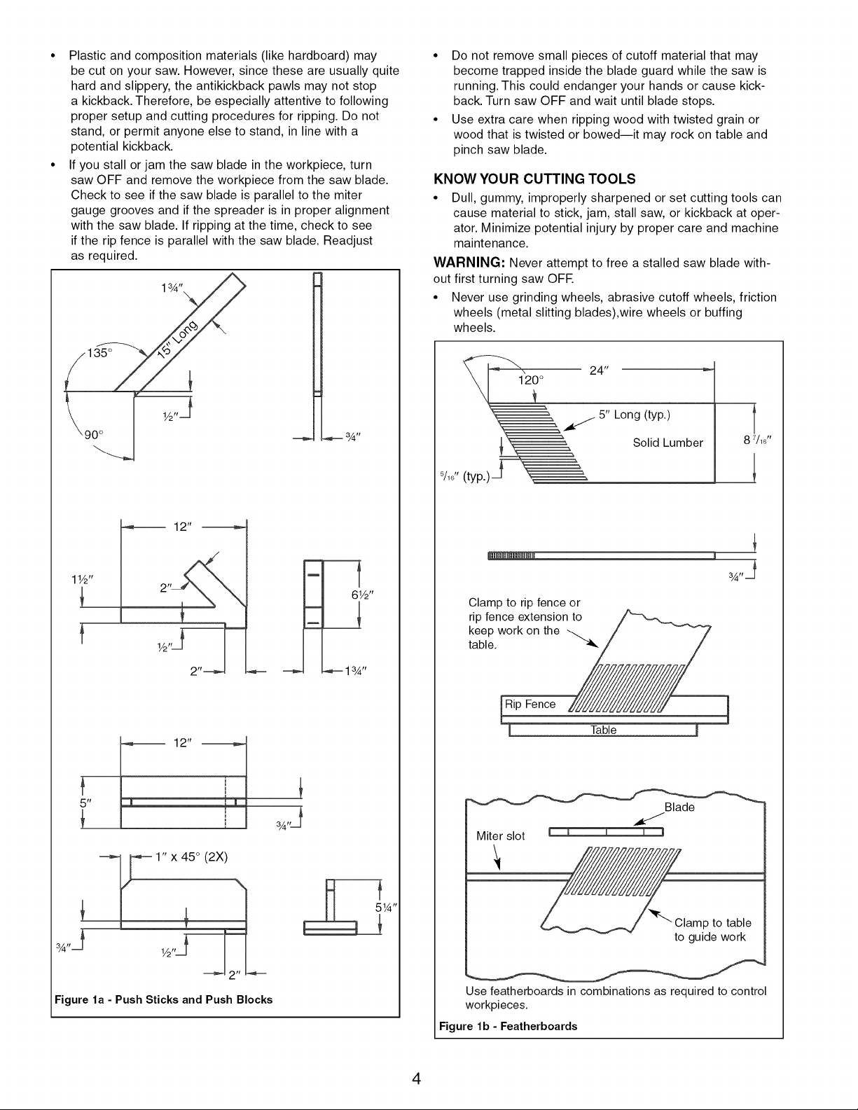
• During rip and rip-type cuts, workpiece must be held down
on table and against fence with a push stick, push block,
or featherboards, as applicable (see Figures la and lb,
page 4).
Push Stick: A safety device used to push the workpiece
through a cutting operation. Used most often when rip cutting
thin workpieces.
The push stick and push block examples shown are useful for
keeping hands and fingers away from saw blade during ripping,
rabbeting and dadoing. Apply downward pressure and push
workpiece through the cut and past the blades. Several other
configurations may be suitable for safe operation.
Featherboards are used to keep the work in contact with the rip
fence or table during the cutting operation. Use of featherboards
can help to prevent kickbacks and binding. Featherboards
should be used for all "non thru-sawing" operations.
• Never reach in back of the cutting tool with either hand to
hold down or support the workpiece, remove wood scraps,
or for any other reason. Avoid awkward operations and
hand positions where a sudden slip could cause fingers
or hand to move into a saw blade or other cutting tool.
• Do not perform layout, assembly, or setup work on the
table while the cutting tool is rotating.
• Do not perform any operation freehandialways use either
rip fence or miter gauge to position and guide the work.
• Never use the rip fence when cross-cutting or the miter gauge
when ripping. Do not use rip fence as a length stop. Never
hold onto or touch free-end of workpiece or a free-piece that
is cut off, while power is ON and/or saw blade is rotating.
• Shut the saw OFF and disconnect power source when
removing the table insert, changing the cutting tool,
removing or replacing the blade guard, or making
adjustments.
• To prevent unauthorized use, lock the start switch using
provided padlock.
• Provide adequate support to the rear and sides of the
saw table for wide or long workpieces.
3
• Plastic and composition materials (like hardboard) may
be cut on your saw. However, since these are usually quite
hard and slippery, the antikickback pawls may not stop
a kickback. Therefore, be especially attentive to following
proper setup and cutting procedures for ripping. Do not
stand, or permit anyone else to stand, in line with a
potential kickback.
• If you stall or jam the saw blade in the workpiece, turn
saw OFF and remove the workpiece from the saw blade.
Check to see if the saw blade is parallel to the miter
gauge grooves and if the spreader is in proper alignment
with the saw blade. If ripping at the time, check to see
if the rip fence is parallel with the saw blade. Readjust
as required.
• Do not remove small pieces of cutoff material that may
become trapped inside the blade guard while the saw is
running. This could endanger your hands or cause kick-
back. Turn saw OFF and wait until blade stops.
• Use extra care when ripping wood with twisted grain or
wood that is twisted or bowediit may rock on table and
pinch saw blade.
KNOW YOUR CUTTING TOOLS
• Dull, gummy, improperly sharpened or set cutting tools can
cause material to stick, jam, stall saw, or kickback at oper-
ator. Minimize potential injury by proper care and machine
maintenance.
WARNING: Never attempt to free a stalled saw blade with-
out first turning saw OFE
• Never use grinding wheels, abrasive cutoff wheels, friction
wheels (metal slitting blades),wire wheels or buffing
wheels.
24 ,r
5" Long (typ.)
Solid Lumber
1 1/2'r
5/16 't (typ.) _,__
12"
Clamp to rip fence or
rip fence extension to
keep work on the
table.
2
Rip Fence
l Table
5 'r
Blade
Miter slot
1" x 45 ° (2X)
¾,,j
Figure la - Push Sticks and Push Blocks
V2"J--
p to table
to guide work
Use featherboards in combinations as required to control
workpieces.
Figure lb - Featherboards
4
USE ONLY ACCESSORIES DESIGNED FOR SAW
• Crosscutting operations are worked more conveniently and
with greater safety if an auxiliary wood facing is attached
to miter gauge using holes provided. However, facing must
not interfere with proper functioning of saw blade guard.
• Make sure the top of the arbor or cutting tool rotates
toward you when standing in normal operating position.
Also make sure the cutting tool, blade flange and arbor
nut are installed properly. Keep the cutting tool as low
as possible for the operation being performed. Keep all
guards in place whenever possible.
• Do not use any blade or other cutting tool marked for oper-
ating speed less than 4000 RPM. Never use a cutting tool
larger in diameter than diameter for which saw was
designed. For greatest safety and efficiency when ripping,
use maximum diameter blade for which saw is designed,
since under these conditions spreader is nearest the
blade.
• Adjust table inserts flush with table top. Never operate saw
unless proper insert is installed.
• Never feed material into the cutting tool from the rear of
the saw. An accident and serious injury could result.
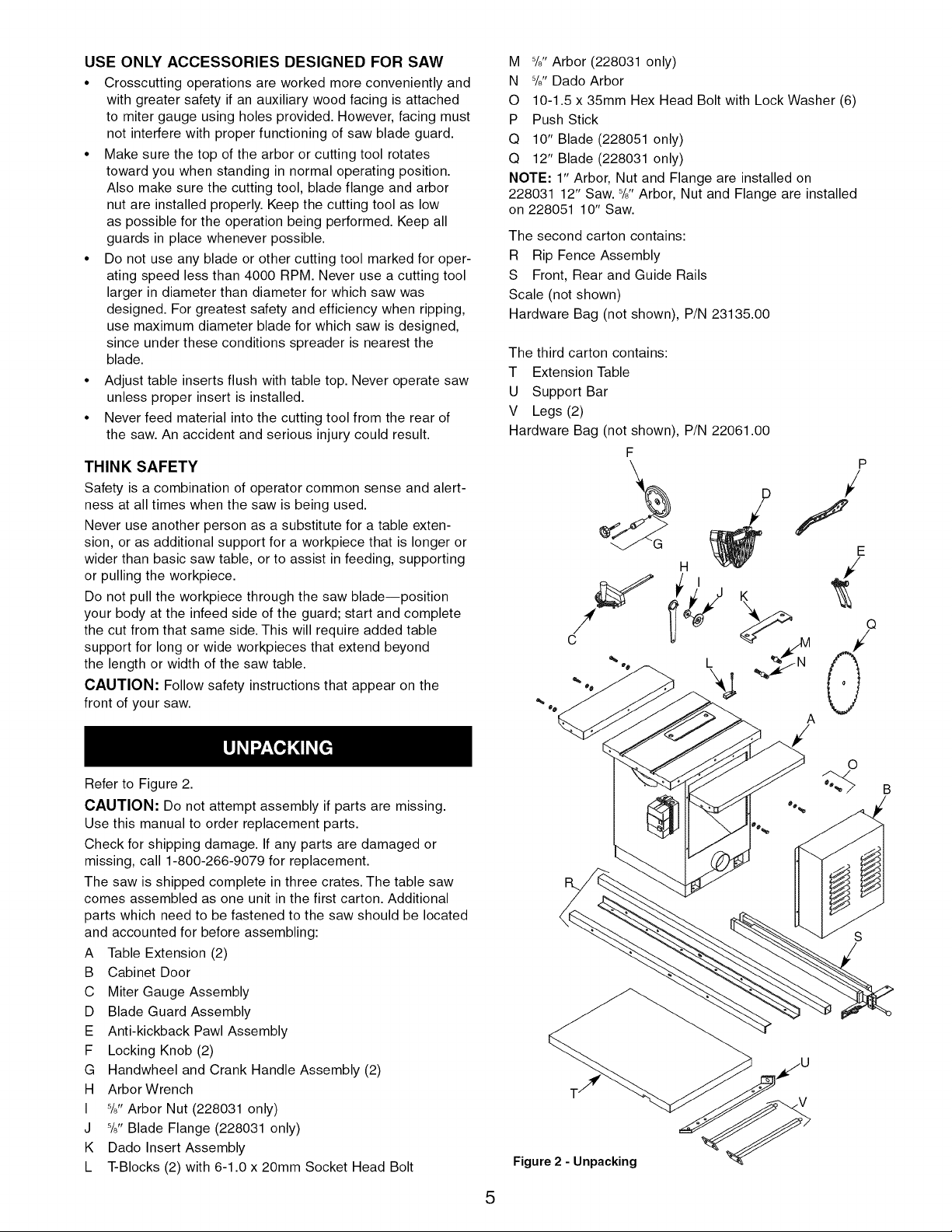
M %" Arbor (228031 only)
N 5/8"Dado Arbor
O 10-1.5 x 35mm Hex Head Bolt with Lock Washer (6)
P Push Stick
Q 10" Blade (228051 only)
Q 12" Blade (228031 only)
NOTE: 1" Arbor, Nut and Flange are installed on
228031 12" Saw. %" Arbor, Nut and Flange are installed
on 228051 10" Saw.
The second carton contains:
R Rip Fence Assembly
S Front, Rear and Guide Rails
Scale (not shown)
Hardware Bag (not shown), P/N 23135.00
The third carton contains:
T Extension Table
U Support Bar
V Legs (2)
Hardware Bag (not shown), P/N 22061.00
THINK SAFETY
Safety is a combination of operator common sense and alert-
ness at all times when the saw is being used.
Never use another person as a substitute for a table exten-
sion, or as additional support for a workpiece that is longer or
wider than basic saw table, or to assist in feeding, supporting
or pulling the workpiece.
Do not pull the workpiece through the saw blade--position
your body at the infeed side of the guard; start and complete
the cut from that same side. This will require added table
support for long or wide workpieces that extend beyond
the length or width of the saw table.
CAUTION: Follow safety instructions that appear on the
front of your saw.
Refer to Figure 2.
CAUTION: Do not attempt assembly if parts are missing.
Use this manual to order replacement parts.
Check for shipping damage. If any parts are damaged or
missing, call 1-800-266-9079 for replacement.
The saw is shipped complete in three crates. The table saw
comes assembled as one unit in the first carton. Additional
parts which need to be fastened to the saw should be located
and accounted for before assembling:
A Table Extension (2)
B Cabinet Door
C Miter Gauge Assembly
D Blade Guard Assembly
E Anti-kickback Pawl Assembly
F Locking Knob (2)
G Handwheel and Crank Handle Assembly (2)
H Arbor Wrench
I 5/8"Arbor Nut (228031 only)
J 5/8"Blade Flange (228031 only)
K Dado Insert Assembly
L T-Blocks (2) with 6-1.0 x 20mm Socket Head Bolt
P
/
f
E
A
o
B
Figure 2 - Unpacking
5
IMPORTANT:Tableiscoatedwithaprotectant.Toensure
properfitandoperation,removecoating.Coatingiseasily
removedwithmildsolvents,suchasmineralspirits,anda
softcloth.Avoidgettingsolutiononpaintoranyoftherubber
orplasticparts.Solventsmaydeterioratethesefinishes.Use
soapandwateronpaint,plasticorrubbercomponents.After
cleaning,coverallexposedsurfaceswithalightcoatingofoil.
Pastewaxisrecommendedfortabletop.
WARNING:Neverusehighlyvolatilesolvents.Nonflamma-
blesolventsarerecommendedtoavoidpossiblefirehazard.
RefertoFigures3-12,pages6,9and16-27.
CAUTION:Donotattemptassemblyifpartsaremissing.
Usethismanualtoorderreplacementparts.
Becertainallpartsarecleanandfreeofshippingpreserva-
tive.Also,completelyremoveallpartsofcrateandpacking.
Sawcabinetshouldbedirectlyonthefloor.
SAWINSTALLATION
Positioningthesawonalevelsurface(shimmingmaybe
required)willimprovestabilityandaccuracyandprevent
warpageandfailureofcastcomponentsandwelds.Levelthe
sawusingshimsormachinemounts.Thestationarysaw's
baseisfittedwithfourmountingholes.Theholesarelocated
withinanorangerecess.Usetheseholestosecurestationary
sawtothefloor.Thissawshouldbepermanentlyfastenedto
thefloor.Thiswilldecreasevibrationandincreasestability.
DANGER:Thedrivepulleyandmotorpulleyfurnished,will
runthebladeatapproximately4000RPMwhenusedwith
3500RPMmotor.Neversubstitutethesepulleystoincrease
thisspeedbecauseitcouldbedangerous.
ARBOR EXTENSION INSTALLATION
Refer to Figure 9, page 20.
° Wipe clean taper and threads of arbor extension (No. 36).
It is recommended when installing that a dry lubricant be
used on taper end of arbor extension.
• Install arbor extension (No. 36) into arbor (No. 35).
Standard arbor extension for 12" saw (228031) is 1" O.D.
x 3" long. By hand, thread arbor extension by inserting
8mm hex wrench (not shown) into 8mm socket at outboard
end of extension and tighten. Arbor itself is held in place
with spanner wrench (No. 39). Place spanner wrench on
inside blade flange with two prongs on spanner wrench
inserted into two holes in flange. Seat arbor extension
firmly. However, it is not necessary to excessively tighten.
NOTE: To remove an arbor extension, follow the preceding
steps in reverse order.
BLADE INSTALLATION
Refer to Figure 9, page 20.
NOTE: 228031 is supplied with a 12" x 1" 40T blade. 228051
is supplied with a 10" x %" 40T blade.
WARNING: Turn the power switch OFF and unplug the power
cord from its power source when changing the saw blade.
WARNING: When replacing blades, check the thickness
stamped onto the riving knife. You must select a blade with
a kerr width larger than the thickness of the riving knife. The
kerr width should be marked on the blade or blade package.
Thinner blades may cause the workpiece to bind during cutting.
228051 -2.5mm thick riving knife. Only use for 10" diameter
blade with 3.0mm min. kerf width and 2.0mm max. body
thickness.
228031 -2.5mm thick riving knife. Only use for 12" diameter
blade with 3.0mm min. kerf width and 2.0mm max. body
thickness.
• Remove arbor nut and blade flange (Nos. 37 and 38)
from the arbor.
• Check that arbor diameter matches mounting hole of
blade. 12" saw, 228031, is supplied with a 1" standard
arbor extension. 10" saw, 228051, is supplied with a 5/8"
standard arbor extension. If necessary, remove incorrect
arbor extension using spanner wrench (No. 39) and hex
wrench supplied.
• Mount required arbor extension to arbor; be sure that
arbor and arbor extension are clean and free of dirt,
chips, etc. Tighten arbor extension securely in arbor.
• Mount blade onto the arbor extension. Be sure blade is
mounted so that it spins in proper direction. Replace
arbor flange and nut. Tighten nut securely.
IMPORTANT: Blade rotates towards front of saw. When
installing blade, make sure teeth are pointing towards front
of the saw.
NOTE: Do not over tighten arbor nut. Use the arbor wrench
to just "snug" it.
ASSEMBLE HANDWHEELS
Refer to Figures 10 and 11, pages 22 and 24.
• Both handwheels are identical. Attach crank handles
(Fig. 11, No. 13) securely to handwheels (Fig. 11, No. 27).
• Handwheels are attached to tilt adjustment shaft (Fig. 10,
No. 4) and height adjustment shaft (Fig. 10, No. 24).
• Place key (Fig. 10, No. 6) in keyway. Assemble handwheel
to shaft engaging set screw (Fig. 11, No. 28) with key in
shaft. Position handwheel onto shaft as far as possible
without interfering with movement. Tighten set screw.
• Install locking knobs (Fig. 11, No. 23). Insert threaded por-
tion of knobs into end of shafts. Gently hand tighten until
it stops. This is locked position. To unlock, back out knob
three complete turns. For now, leave handwheels unlocked.
NOTE: Do not over tighten locking knobs.
CHECK TABLE ALIGNMENT
Refer to Figures 3 and 11, pages 6 and 24.
• Saws are shipped from the factory with the table adjusted
so the miter gauge slots are parallel to the saw blade.
However, in order to obtain the best results from the saw, it
is suggested this adjustment be checked before operating.
• A simple method of checking alignment is as follows: Bolt
or clamp a dowel rod or similar object to miter gauge (a
combination square can be substituted).Pick out a tooth
on front of blade and set the dowel to it so it is just touch-
ing. Move same tooth to back of blade.
• Gauge this tooth with the dowel rod. If the tooth is in the
same position, relative to the miter gauge, the table is par-
allel with the blade. In short, the miter gauge slots must be
parallel with the blade. This means that when measuring
distance between blade and slot at the front and rear of the
blade, the distances will be equal (see Figure 3, page 7).
6
NOTE: Be positive to measure the distance or make the test
on the same tooth of the saw blade in both front and rear
positions.
• If an adjustment is necessary, proceed as follows: (Refer
to Figures 3 and 11). Loosen the hex head bolts and lock
washers (Fig. 11, Nos. 4 and 10) to the cabinet (Fig. 11,
No. 11). Shift the table until a position is found where
the saw blade is parallel to the miter gauge slots.
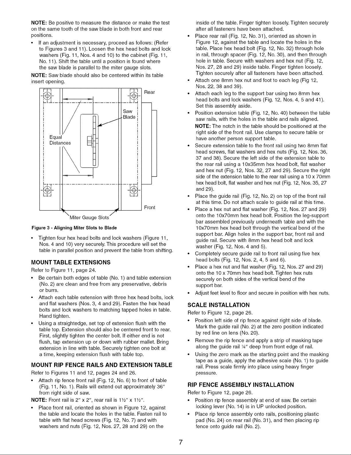
NOTE: Saw blade should also be centered within its table
insert opening.
_=_._
Rear
,-- =J= J=q
,
_aw ',
Blade ',
,
I
,
I
,
I
,
I
,
I
,
I
I
,
I
,
L.Y,3
Front
l_Miter Gauge Slots "_1_
Figure 3 - Aligning Miter Slots to Blade
Tighten four hex head bolts and lock washers (Figure 11,
Nos. 4 and 10) very securely. This procedure will set the
table in parallel position and prevent the table from shifting.
MOUNT TABLE EXTENSIONS
Refer to Figure 11, page 24.
• Be certain both edges of table (No. 1) and table extension
(No. 2) are clean and free from any preservative, debris
or burrs.
• Attach each table extension with three hex head bolts, lock
and flat washers (Nos. 3, 4 and 29). Fasten the hex head
bolts and lock washers to matching tapped holes in table.
Hand tighten.
• Using a straightedge, set top of extension flush with the
table top. Extension should also be centered front to rear.
First, slightly tighten the center bolt. If either end is not
flush, tap extension up or down with rubber mallet. Bring
extension in line with table. Securely tighten one bolt at
a time, keeping extension flush with table top.
MOUNT RIP FENCE RAILS AND EXTENSION TABLE
Refer to Figures 11 and 12, pages 24 and 26.
• Attach rip fence front rail (Fig. 12, No. 6) to front of table
(Fig. 11, No. 1). Rails will extend out approximately 36"
from right side of saw.
NOTE: Front rail is 2" x 2", rear rail is 1W' x 1Y#'.
• Place front rail, oriented as shown in Figure 12, against
the table and locate the holes in the table. Fasten rail to
table with flat head screws (Fig. 12, No. 7) and with
washers and nuts (Fig. 12, Nos. 27, 28 and 29) on the
inside of the table. Finger tighten loosely. Tighten securely
after all fasteners have been attached.
• Place rear rail (Fig. 12, No. 31), oriented as shown in
Figure 12, against the table and locate the holes in the
table. Place hex head bolt (Fig. 12, No. 32) through hole
in rail, through spacer (Fig. 12, No. 30), and then through
hole in table. Secure with washers and hex nut (Fig. 12,
Nos. 27, 28 and 29) inside table. Finger tighten loosely.
Tighten securely after all fasteners have been attached.
• Attach one 8mm hex nut and foot to each leg (Fig 12,
Nos. 22, 38 and 39).
• Attach each leg to the support bar using two 8mm hex
head bolts and lock washers (Fig. 12, Nos. 4, 5 and 41).
Set this assembly aside.
• Position extension table (Fig. 12, No. 40) between the table
saw rails, with the holes in the table and rails aligned.
NOTE: The notch in the table should be positioned at the
right side of the front rail. Use clamps to secure table or
have another person support table.
• Secure extension table to the front rail using two 8mm flat
head screws, flat washers and hex nuts (Fig. 12, Nos. 36,
37 and 38). Secure the left side of the extension table to
the rear rail using a 10x35mm hex head bolt, flat washer
and hex nut (Fig. 12, Nos. 32, 27 and 29). Secure the right
side of the extension table to the rear rail using a 10 x 70mm
hex head bolt, flat washer and hex nut (Fig. 12, Nos. 35, 27
and 29).
• Place the guide rail (Fig. 12, No. 2) on top of the front rail
at this time. Do not attach scale to guide rail at this time.
• Place a hex nut and flat washer (Fig. 12, Nos. 27 and 29)
onto the lOx7Omm hex head bolt. Position the leg-support
bar assembled previously underneath table and with the
lOx7Omm hex head bolt through the vertical bend of the
support bar. Align holes in the support bar, front rail and
guide rail. Secure with 8mm hex head bolt and lock
washer (Fig. 12, Nos. 4 and 5).
• Completely secure guide rail to front rail using five hex
head bolts (Fig. 12, Nos. 2, 4, 5 and 6).
• Place a hex nut and flat washer (Fig. 12, Nos. 27 and 29)
onto the 10 x 70mm hex head bolt. Tighten hex nuts
securely on both sides of the vertical bend of the
support bar.
• Adjust feet level to floor and secure in position with hex nuts.
SCALE INSTALLATION
Refer to Figure 12, page 26.
• Position left side of rip fence against right side of blade.
Mark the guide rail (No. 2) at the zero position indicated
by red line on lens (No. 20).
• Remove the rip fence and apply a strip of masking tape
along the guide rail 1/4"deep from front edge of rail.
• Using the zero mark as the starting point and the masking
tape as a guide, apply the adhesive scale (No. 1) to guide
rail. Press scale firmly into place using heavy finger
pressure.
RIP FENCE ASSEMBLY INSTALLATION
Refer to Figure 12, page 26.
• Position rip fence assembly at end of saw. Be certain
locking lever (No. 14) is in UP unlocked position.
• Place rip fence assembly onto rails, positioning plastic
pad (No. 24) on rear rail (No. 31), and then placing rip
fence onto guide rail (No. 2).
7
• Rip fence should now ride freely on rip fence rails. Once
rip fence is completely installed, it should be thoroughly
adjusted. (See Operation, page 12, Rip fence adjustment.)
POSITION AND ADJUST RIVING KNIFE
Refer to Figure 9, page 20.
• Riving knife is installed on the saw. Raise the blade com-
pletely to access the riving knife.
• Loosen the wing nut (Key No. 26) and raise the riving knife
to its highest position. Riving knife has two holes for two
positions. The highest position is for all thru cuts. The
lowest position is for dado cuts.
• Make sure locking pin (Key No. 19) is aligned with riving
knife hole and secure in position by tightening wing nut.
• Riving knife must be in line with blade. Make sure riving
knife sits flat against mounting bracket and lock plate
(Key Nos. 21 and 27).
RIVING KNIFE TO BLADE ADJUSTMENT
Refer to Figure 9, page 20.
• Riving knife to blade clearance: the gap between the riving
knife and the saw blade should be an even distance
across the entire radius.
• The riving knife should also be in line with the saw blade.
If adjustment is necessary:
1. Locate the riving knife bracket (Key No. 21).
2. Loosen the two socket head cap screws (Key No. 13)
slightly enough to move the bracket, bringing the riving
knife in line with the saw blade. Make sure the gap
between the blade and knife is even and from 1/4to 5/16"
in distance.
3. Once the riving knife is aligned with the blade, tighten
the socket head cap screws.
TABLE INSERTS INSTALLATION
Refer to Figure 11, page 24.
• Be certain standard insert (No. 5) and Dado Insert (No. 6)
are clean. Lower blade below table. Place standard insert
into position with cut-out on blade side.
• Surface of insert should be flush with table surface. Using
a straightedge, check insert to see if it is flush with table.
To adjust insert, remove insert from table and turn it
upside down on work bench.
• Each corner of table insert is fitted with an adjusting
setscrew. Adjust each corner of insert up or down to
bring insert flush with table top. Be certain all four
setscrews are firmly seated on table casting.
• Repeat procedure for dado insert (No. 6). Replace stan-
dard table insert (No. 5).
CAUTION: Only use dado insert (Fig. 11, No. 6) with dado
blade set. Only use standard insert (Fig. 11, No. 5) with stan-
dard blade. Never attempt to interchange; only use table
insert with the blade it was intended to be used with.
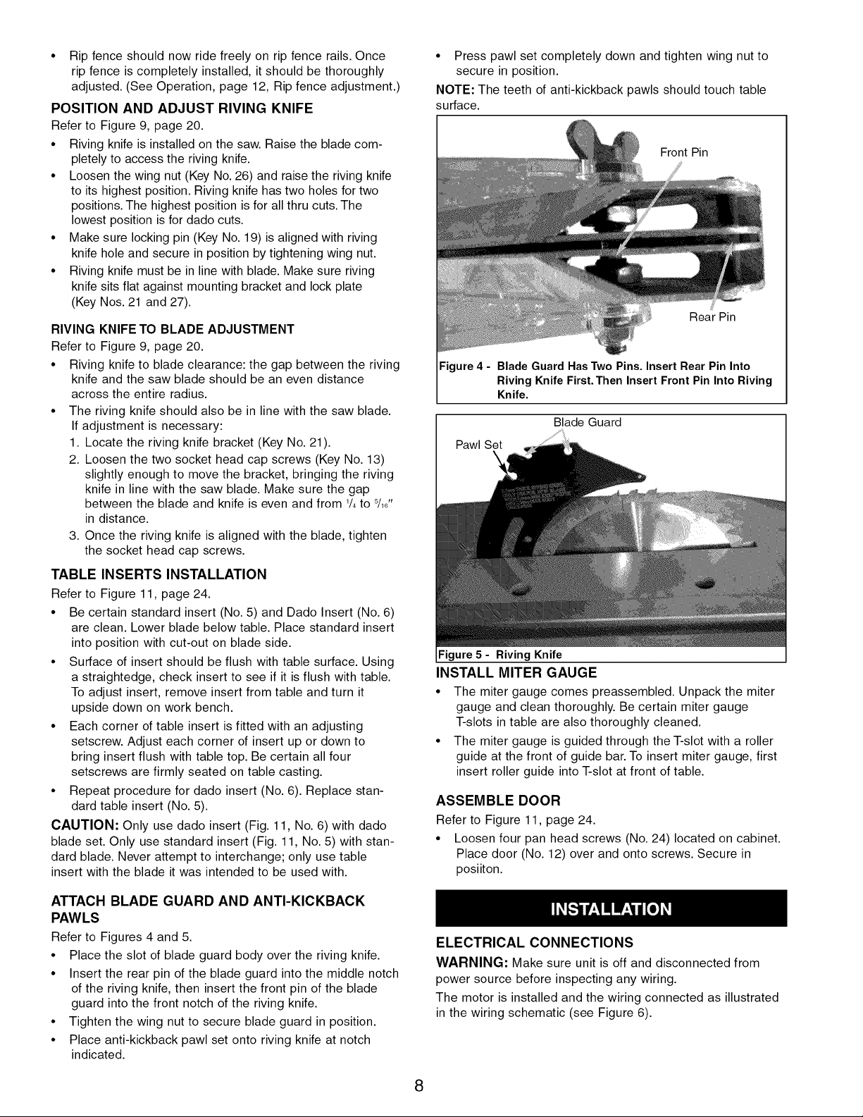
• Press pawl set completely down and tighten wing nut to
secure in position.
NOTE: The teeth of anti-kickback pawls should touch table
surface.
Front Pin
Rear Pin
Figure 4 - Blade Guard Has Two Pins. Insert Rear Pin Into
Riving Knife First. Then Insert Front Pin Into Riving
Knife.
Blade Guard
Pawl Set
Figure5 - Riving Knife
INSTALL MITER GAUGE
• The miter gauge comes preassembled. Unpack the miter
gauge and clean thoroughly. Be certain miter gauge
T-slots in table are also thoroughly cleaned.
• The miter gauge is guided through the T-slot with a roller
guide at the front of guide bar. To insert miter gauge, first
insert roller guide into T-slot at front of table.
ASSEMBLE DOOR
Refer to Figure 11, page 24.
• Loosen four pan head screws (No. 24) located on cabinet.
Place door (No. 12) over and onto screws. Secure in
posiiton.
ATTACH BLADE GUARD AND ANTI-KICKBACK
PAWLS
Refer to Figures 4 and 5.
• Place the slot of blade guard body over the riving knife.
• Insert the rear pin of the blade guard into the middle notch
of the riving knife, then insert the front pin of the blade
guard into the front notch of the riving knife.
• Tighten the wing nut to secure blade guard in position.
• Place anti-kickback pawl set onto riving knife at notch
indicated.
ELECTRICAL CONNECTIONS
WARNING: Make sure unit is off and disconnected from
power source before inspecting any wiring.
The motor is installed and the wiring connected as illustrated
in the wiring schematic (see Figure 6).
8
WIRE MOTOR TO CONTACTOR
• See wiring schematic supplied with motor and wire motor
for 230 volt operation, clockwise rotation as viewed from
shaft end of motor.
• Wire motor to motor cord which is connected to terminals
2 and 6 on the contactor thermal overload.
• Be sure to use strain relief supplied to secure motor cord
in motor junction box knock-out. Be sure green ground
wire on motor cord is properly grounded to motor inside
junction box. Use wire nuts and electrical tape to connect
and insulate wires.
NOTE: Motor must run in a clockwise rotation. (Viewing top of
blade, teeth must rotate from rear to front of saw.) If saw does
not rotate in proper direction, wiring and all connections must
be checked and corrected.
WARNING: Once rotation is checked, disconnect power
before working with motor or tool.
WIRE MAGNETIC STARTER TO SOURCE
Refer to Figure 6.
The saw should be connected to power source with perma-
nent wiring (hard wired). Power leads are to be supplied and
connected by a qualified electrician.
IMPORTANT: Motor and magnetic starter must be properly
grounded. Wiring should be performed by a qualified electri-
cian according to all local codes and ordinances.
• Be certain power leads are sufficient in size to adequately
carry the saw's voltage and amp load.
• Ground the magnetic starter. Connect the ground lead to
magnetic starter's ground screw. The ground lead will be
green or green with yellow stripe. Fasten securely.
• Power leads are connected to magnetic starter terminals
L1 and L3.
WARNING: Do not connect power leads to any other
terminal or fastener.
• Wire power supply cord into junction box (Figure 11, Ref.
No. 37) on rear of cabinet.
• When wiring the saw to the source, install a fused safety
disconnect switch between the saw and the circuit break-
er. Be certain the safety disconnect switch is capable of
being locked in the OFF position. The safety disconnect
switch is a safety precaution which allows the operator to
lock the saw OFF so it is unable to receive power. This
feature is intended to prevent accidental start-up when
maintaining or servicing saw. In addition, it is intended to
prevent unauthorized and possible hazardous use by oth-
ers. A key lock switch is provided on the tool for the same
reasons.
• The safety disconnect switch is fused. Protect the saw with
a 20 amp time-delay fuse or 20 amp manual reset circuit
breaker. Do not use fuses or breakers with a greater
amperage rating.
• Wire the saw to a breaker box or fuse box with adequate
capacity wire to accommodate the stationary saw's volt-
age and amp load.
IMPORTANT: Be certain saw is wired to a circuit protected by
a 20 amp breaker or fuse.
• Wire the saw to a breaker box or fuse box with adequate
capacity wire to accommodate the stationary saw's volt-
age and amp load.
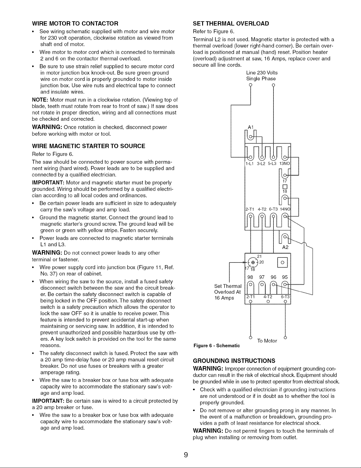
SET THERMAL OVERLOAD
Refer to Figure 6.
Terminal L2 is not used. Magnetic starter is protected with a
thermal overload (lower right-hand corner). Be certain over-
load is positioned at manual (hand) reset. Position heater
(overload) adjustment at saw, 16 Amps, replace cover and
secure all line cords.
Line 230 Volts
Single Phase
_l
A]
]-k] 3-L2 5-1_3 ]3NO m
_J
2-T] 4-T2 6-T3 ]4NQ
Set Thermal
Overload At
16 Amps
4-T2
lOT
Figure 6 - Schematic
GROUNDING INSTRUCTIONS
WARNING: Improper connection of equipment grounding con-
ductor can result in the risk of electrical shock. Equipment should
be grounded while in use to protect operator from electrical shock.
• Check with a qualified electrician if grounding instructions
are not understood or if in doubt as to whether the tool is
properly grounded.
• Do not remove or alter grounding prong in any manner. In
the event of a malfunction or breakdown, grounding pro-
vides a path of least resistance for electrical shock.
WARNING: Do not permit fingers to touch the terminals of
plug when installing or removing from outlet.
To Motor
9
• Plug must be plugged into matching outlet that is properly
installed and grounded in accordance with all local codes and
ordinances. Do not modify plug provided. If it will not fit in
outlet, have proper outlet installed by a qualified electrician.
• Inspect tool cords periodically and if damaged, have them
repaired by an authorized service facility.
• Green (or green and yellow) conductor in cord is the
grounding wire. If repair or replacement of the electric cord
or plug is necessary, do not connect the green (or green
and yellow) wire to a live terminal.
• Many cover plate screws, water pipes and outlet boxes are
not properly grounded. To ensure proper ground, grounding
means must be tested by a qualified electrician.
EXTENSION CORDS
The use of any extension cord will cause some drop in
voltage and loss of power.
Wires of the extension cord must be of sufficient size to
carry the current and maintain adequate voltage.
Use the table to determine the minimum wire size (A.W.G.)
extension cord.
Use only 3-wire extension cords having 3-prong grounding
type plugs and 3-pole receptacles which accept the tool plug.
If the extension cord is worn, cut, or damaged in any way,
replace it immediately.
Extension Cord Length (230V Operation)
Wire Size A.W.G.
Up to 50 ft....................................... 14
50 to 100 ft ....................................... 12
NOTE: Using extension cords over 100 ft. long is not
recommended.
Refer to Figures 7-12, pages 17-27.
DESCRIPTION
The Craftsman 10" Model Number 228051 and 12" Model
Number 228031 tilting arbor saws, offer precise cutting perfor-
mance for all woods up to 3" thick (10" saw) and 4" thick (12"
Saw). The saws are designed for the professional user and
are ruggedly constructed for continuous service. The saws are
designed to be permanently located in a shop or plant. The
10" Saw is recommended for use with a 10" blade and the
12"Saw is recommended for use with a 10" or 12" blade.
The saws feature an extra large solid cast-iron table. A unique
system of T-slots incorporates the cast iron miter gauge as
well as two rip fence alignment T-blocks. Saws are equipped
with a clear acrylic blade guard and antikickback feature.
Cabinet is constructed of heaw gauge welded steel, totally
enclosed and is ported for a 4" vacuum hose.
Saws include: 5/8"dia. arbor, %" dia. dado arbor, 1" dia. arbor
(12" saw only), dado table insert, and a three V-belt drive sys-
tem.
Rip Fence Assemblies, feature heavy-duty precision rip
fences that are designed for simple and one-hand maneuver-
ability. They include a front rail calibrated in inches and mil-
limeters with a magnified window for close tolerances.
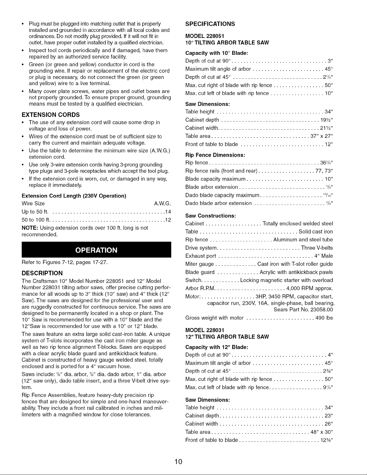
SPECIFICATIONS
MODEL 228051
10" TILTING ARBOR TABLE SAW
Capacity with 10" Blade:
Depth of cut at 90 ° . ............................... 3"
Maximum tilt angle of arbor ........................ 45 °
Depth of cut at 45 ° . ............................. 21/8''
Max. cut right of blade with rip fence ................. 50"
Max. cut left of blade with rip fence .................. 10"
Saw Dimensions:
Table height .................................... 34"
Cabinet depth ................................. 191/2''
Cabinet width .................................. 211/2"
Table area ................................. 37" x 27"
Front of table to blade ............................ 12"
Rip Fence Dimensions:
Rip fence ..................................... 36%"
Rip fence rails (front and rear) ................... 77, 73"
Blade capacity maximum .......................... 10"
Blade arbor extension ............................. 8/8"
Dado blade capacity maximum ..................... 13/18"
Dado blade arbor extension ........................ 8/8"
Saw Constructions:
Cabinet ................... Totally enclosed welded steel
Table ................................. Solid cast iron
Rip fence ..................... Aluminum and steel tube
Drive system ............................ Three V-belts
Exhaust port ................................ 4" Male
Miter gauge .............. Cast iron with T-slot roller guide
Blade guard .............. Acrylic with antikickback pawls
Switch ............. Locking magnetic starter with overload
Arbor R.P.M........................ 4,000 RPM approx.
Motor: .................. 3HP, 3450 RPM, capacitor start,
capacitor run, 230V, 16A, single-phase, ball bearing,
Sears Part No. 23058.00
Gross weight with motor ....................... 490 Ibs
MODEL 228031
12" TILTING ARBOR TABLE SAW
Capacity with 12" Blade:
Depth of cut at 90 ° . ............................... 4"
Maximum tilt angle of arbor ........................ 45 °
Depth of cut at 45 ° . ............................. 23/4"
Max. cut right of blade with rip fence ................. 50"
Max. cut left of blade with rip fence .................. 91/8',
Saw Dimensions:
Table height .................................... 34"
Cabinet depth ................................... 23"
Cabinet width ................................... 26"
Table area ................................. 48" x 30"
Front of table to blade ........................... 123/4''
10
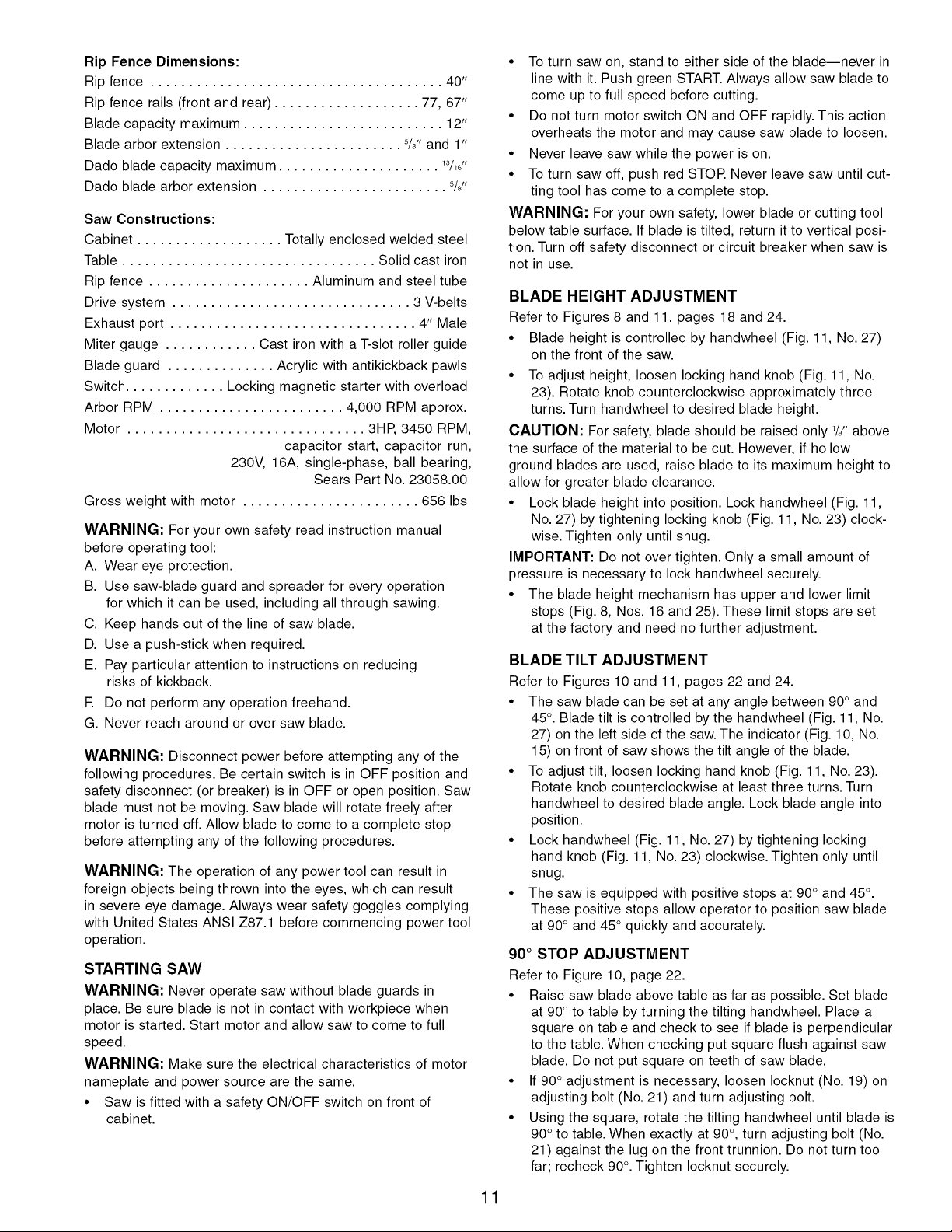
Rip Fence Dimensions:
Rip fence ...................................... 40"
Rip fence rails (front and rear) ................... 77, 67"
Blade capacity maximum .......................... 12"
Blade arbor extension ....................... 5/8"and 1"
Dado blade capacity maximum ..................... 13/18"
Dado blade arbor extension ........................ 8/8"
Saw Constructions:
Cabinet ................... Totally enclosed welded steel
Table ................................. Solid cast iron
Rip fence ..................... Aluminum and steel tube
Drive system ............................... 3 V-belts
Exhaust port ................................ 4" Male
Miter gauge ............ Cast iron with a T-slot roller guide
Blade guard .............. Acrylic with antikickback pawls
Switch ............. Locking magnetic starter with overload
Arbor RPM ........................ 4,000 RPM approx.
Motor ............................... 3HP, 3450 RPM,
capacitor start, capacitor run,
230V, 16A, single-phase, ball bearing,
Sears Part No. 23058.00
Gross weight with motor ....................... 656 Ibs
WARNING: For your own safety read instruction manual
before operating tool:
A. Wear eye protection.
B. Use saw-blade guard and spreader for every operation
for which it can be used, including all through sawing.
C. Keep hands out of the line of saw blade.
D. Use a push-stick when required.
E. Pay particular attention to instructions on reducing
risks of kickback.
E Do not perform any operation freehand.
G. Never reach around or over saw blade.
WARNING: Disconnect power before attempting any of the
following procedures. Be certain switch is in OFF position and
safety disconnect (or breaker) is in OFF or open position. Saw
blade must not be moving. Saw blade will rotate freely after
motor is turned off. Allow blade to come to a complete stop
before attempting any of the following procedures.
WARNING: The operation of any power tool can result in
foreign objects being thrown into the eyes, which can result
in severe eye damage. Always wear safety goggles complying
with United States ANSI Z87.1 before commencing power tool
operation.
STARTING SAW
WARNING: Never operate saw without blade guards in
place. Be sure blade is not in contact with workpiece when
motor is started. Start motor and allow saw to come to full
speed.
WARNING: Make sure the electrical characteristics of motor
nameplate and power source are the same.
• Saw is fitted with a safety ON/OFF switch on front of
cabinet.
• To turn saw on, stand to either side of the blade--never in
line with it. Push green START. Always allow saw blade to
come up to full speed before cutting.
• Do not turn motor switch ON and OFF rapidly. This action
overheats the motor and may cause saw blade to loosen.
• Never leave saw while the power is on.
• To turn saw off, push red STOP. Never leave saw until cut-
ting tool has come to a complete stop.
WARNING: For your own safety, lower blade or cutting tool
below table surface. If blade is tilted, return it to vertical posi-
tion. Turn off safety disconnect or circuit breaker when saw is
not in use.
BLADE HEIGHT ADJUSTMENT
Refer to Figures 8 and 11, pages 18 and 24.
• Blade height is controlled by handwheel (Fig. 11, No. 27)
on the front of the saw.
• To adjust height, loosen locking hand knob (Fig. 11, No.
23). Rotate knob counterclockwise approximately three
turns. Turn handwheel to desired blade height.
CAUTION: For safety, blade should be raised only 1/3"above
the surface of the material to be cut. However, if hollow
ground blades are used, raise blade to its maximum height to
allow for greater blade clearance.
• Lock blade height into position. Lock handwheel (Fig. 11,
No. 27) by tightening locking knob (Fig. 11, No. 23) clock-
wise. Tighten only until snug.
IMPORTANT: Do not over tighten. Only a small amount of
pressure is necessary to lock handwheel securely.
• The blade height mechanism has upper and lower limit
stops (Fig. 8, Nos. 16 and 25). These limit stops are set
at the factory and need no further adjustment.
BLADE TILT ADJUSTMENT
Refer to Figures 10 and 11, pages 22 and 24.
• The saw blade can be set at any angle between 90° and
45°. Blade tilt is controlled by the handwheel (Fig. 11, No.
27) on the left side of the saw. The indicator (Fig. 10, No.
15) on front of saw shows the tilt angle of the blade.
• To adjust tilt, loosen locking hand knob (Fig. 11, No. 23).
Rotate knob counterclockwise at least three turns. Turn
handwheel to desired blade angle. Lock blade angle into
position.
• Lock handwheel (Fig. 11, No. 27) by tightening locking
hand knob (Fig. 11, No. 23) clockwise. Tighten only until
snug.
• The saw is equipped with positive stops at 90° and 45°.
These positive stops allow operator to position saw blade
at 90° and 45 ° quickly and accurately.
90 ° STOP ADJUSTMENT
Refer to Figure 10, page 22.
• Raise saw blade above table as far as possible. Set blade
at 90° to table by turning the tilting handwheel. Place a
square on table and check to see if blade is perpendicular
to the table. When checking put square flush against saw
blade. Do not put square on teeth of saw blade.
• If 90 ° adjustment is necessary, loosen Iocknut (No. 19) on
adjusting bolt (No. 21) and turn adjusting bolt.
• Using the square, rotate the tilting handwheel until blade is
90° to table. When exactly at 90°, turn adjusting bolt (No.
21) against the lug on the front trunnion. Do not turn too
far; recheck 90°.Tighten Iocknut securely.
11
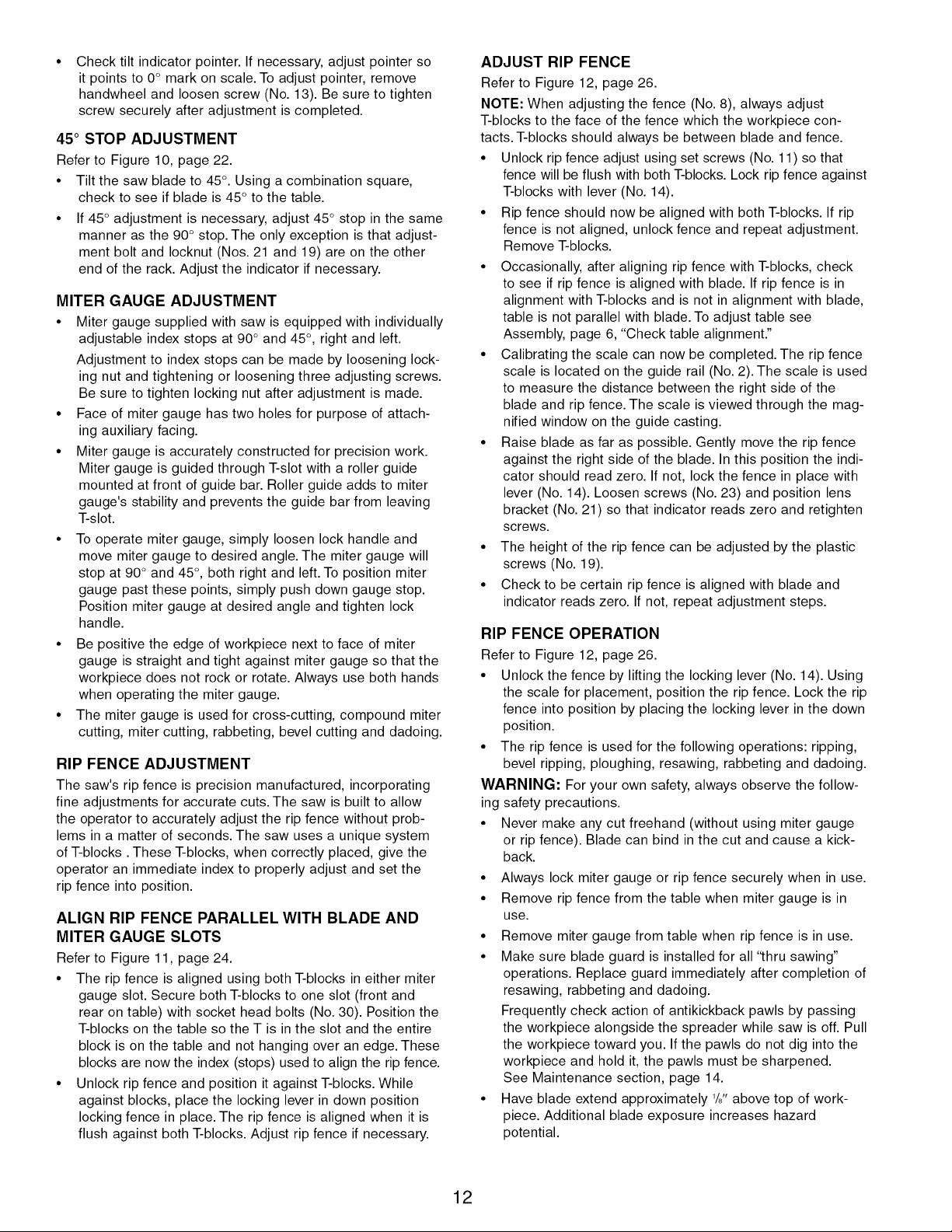
Checktiltindicatorpointer.Ifnecessary,adjustpointerso
itpointsto0°markonscale.Toadjustpointer,remove
handwheelandloosenscrew(No.13).Besuretotighten
screwsecurelyafteradjustmentiscompleted.
45 ° STOP ADJUSTMENT
Refer to Figure 10, page 22.
• Tilt the saw blade to 45°. Using a combination square,
check to see if blade is 45° to the table.
• If 45 ° adjustment is necessary, adjust 45° stop in the same
manner as the 90° stop. The only exception is that adjust-
ment bolt and Iocknut (Nos. 21 and 19) are on the other
end of the rack. Adjust the indicator if necessary.
MITER GAUGE ADJUSTMENT
• Miter gauge supplied with saw is equipped with individually
adjustable index stops at 90° and 45 °, right and left.
Adjustment to index stops can be made by loosening lock-
ing nut and tightening or loosening three adjusting screws.
Be sure to tighten locking nut after adjustment is made.
• Face of miter gauge has two holes for purpose of attach-
ing auxiliary facing.
• Miter gauge is accurately constructed for precision work.
Miter gauge is guided through T-slot with a roller guide
mounted at front of guide bar. Roller guide adds to miter
gauge's stability and prevents the guide bar from leaving
T-slot.
• To operate miter gauge, simply loosen lock handle and
move miter gauge to desired angle. The miter gauge will
stop at 90° and 45 °, both right and left. To position miter
gauge past these points, simply push down gauge stop.
Position miter gauge at desired angle and tighten lock
handle.
• Be positive the edge of workpiece next to face of miter
gauge is straight and tight against miter gauge so that the
workpiece does not rock or rotate. Always use both hands
when operating the miter gauge.
• The miter gauge is used for cross-cutting, compound miter
cutting, miter cutting, rabbeting, bevel cutting and dadoing.
RIP FENCE ADJUSTMENT
The saw's rip fence is precision manufactured, incorporating
fine adjustments for accurate cuts. The saw is built to allow
the operator to accurately adjust the rip fence without prob-
lems in a matter of seconds. The saw uses a unique system
of T-blocks. These T-blocks, when correctly placed, give the
operator an immediate index to properly adjust and set the
rip fence into position.
ALIGN RIP FENCE PARALLEL WITH BLADE AND
MITER GAUGE SLOTS
Refer to Figure 11, page 24.
• The rip fence is aligned using both T-blocks in either miter
gauge slot. Secure both T-blocks to one slot (front and
rear on table) with socket head bolts (No. 30). Position the
T-blocks on the table so the T is in the slot and the entire
block is on the table and not hanging over an edge. These
blocks are now the index (stops) used to align the rip fence.
• Unlock rip fence and position it against T-blocks. While
against blocks, place the locking lever in down position
locking fence in place. The rip fence is aligned when it is
flush against both T-blocks. Adjust rip fence if necessary.
ADJUST RIP FENCE
Refer to Figure 12, page 26.
NOTE: When adjusting the fence (No. 8), always adjust
T-blocks to the face of the fence which the workpiece con-
tacts. T-blocks should always be between blade and fence.
• Unlock rip fence adjust using set screws (No. 11) so that
fence will be flush with both T-blocks. Lock rip fence against
T-blocks with lever (No. 14).
• Rip fence should now be aligned with both T-blocks. If rip
fence is not aligned, unlock fence and repeat adjustment.
Remove T-blocks.
• Occasionally, after aligning rip fence with T-blocks, check
to see if rip fence is aligned with blade. If rip fence is in
alignment with T-blocks and is not in alignment with blade,
table is not parallel with blade. To adjust table see
Assembly, page 6, "Check table alignment."
• Calibrating the scale can now be completed. The rip fence
scale is located on the guide rail (No. 2). The scale is used
to measure the distance between the right side of the
blade and rip fence. The scale is viewed through the mag-
nified window on the guide casting.
• Raise blade as far as possible. Gently move the rip fence
against the right side of the blade. In this position the indi-
cator should read zero. If not, lock the fence in place with
lever (No. 14). Loosen screws (No. 23) and position lens
bracket (No. 21) so that indicator reads zero and retighten
screws.
• The height of the rip fence can be adjusted by the plastic
screws (No. 19).
• Check to be certain rip fence is aligned with blade and
indicator reads zero. If not, repeat adjustment steps.
RIP FENCE OPERATION
Refer to Figure 12, page 26.
• Unlock the fence by lifting the locking lever (No. 14). Using
the scale for placement, position the rip fence. Lock the rip
fence into position by placing the locking lever in the down
position.
• The rip fence is used for the following operations: ripping,
bevel ripping, ploughing, resawing, rabbeting and dadoing.
WARNING: For your own safety, always observe the follow-
ing safety precautions.
• Never make any cut freehand (without using miter gauge
or rip fence). Blade can bind in the cut and cause a kick-
back.
• Always lock miter gauge or rip fence securely when in use.
• Remove rip fence from the table when miter gauge is in
use.
• Remove miter gauge from table when rip fence is in use.
• Make sure blade guard is installed for all '_hru sawing"
operations. Replace guard immediately after completion of
resawing, rabbeting and dadoing.
Frequently check action of antikickback pawls by passing
the workpiece alongside the spreader while saw is off. Pull
the workpiece toward you. If the pawls do not dig into the
workpiece and hold it, the pawls must be sharpened.
See Maintenance section, page 14.
• Have blade extend approximately 1/81tabove top of work-
piece. Additional blade exposure increases hazard
potential.
12
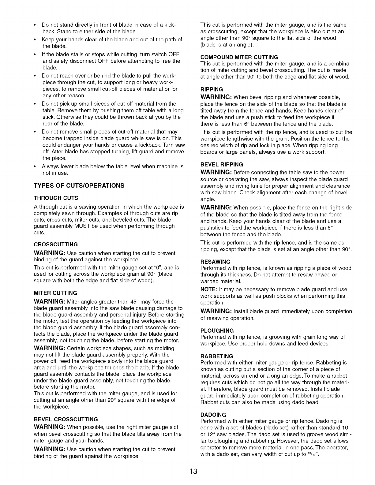
• Do not stand directly in front of blade in case of a kick-
back. Stand to either side of the blade.
• Keep your hands clear of the blade and out of the path of
the blade.
• If the blade stalls or stops while cutting, turn switch OFF
and safety disconnect OFF before attempting to free the
blade.
• Do not reach over or behind the blade to pull the work-
piece through the cut, to support long or heavy work-
pieces, to remove small cut-off pieces of material or for
any other reason.
• Do not pick up small pieces of cut-off material from the
table. Remove them by pushing them off table with a long
stick. Otherwise they could be thrown back at you by the
rear of the blade.
• Do not remove small pieces of cut-off material that may
become trapped inside blade guard while saw is on. This
could endanger your hands or cause a kickback. Turn saw
off. After blade has stopped turning, lift guard and remove
the piece.
• Always lower blade below the table level when machine is
not in use.
TYPES OF CUTS/OPERATIONS
THROUGH CUTS
A through cut is a sawing operation in which the workpiece is
completely sawn through. Examples of through cuts are rip
cuts, cross cuts, miter cuts, and beveled cuts. The blade
guard assembly MUST be used when performing through
cuts.
CROSSCUTTING
WARNING: Use caution when starting the cut to prevent
binding of the guard against the workpiece.
This cut is performed with the miter gauge set at "0", and is
used for cutting across the workpiece grain at 90° (blade
square with both the edge and flat side of wood).
MITER CUTTING
WARNING: Miter angles greater than 45" may force the
blade guard assembly into the saw blade causing damage to
the blade guard assembly and personal injury. Before starting
the motor, test the operation by feeding the workpiece into
the blade guard assembly. If the blade guard assembly con-
tacts the blade, place the workpiece under the blade guard
assembly, not touching the blade, before starting the motor.
WARNING: Certain workpiece shapes, such as molding
may not lift the blade guard assembly properly. With the
power off, feed the workpiece slowly into the blade guard
area and until the workpiece touches the blade. If the blade
guard assembly contacts the blade, place the workpiece
under the blade guard assembly, not touching the blade,
before starting the motor.
This cut is performed with the miter gauge, and is used for
cutting at an angle other than 90 ° square with the edge of
the workpiece.
BEVEL CROSSCUTTING
WARNING: When possible, use the right miter gauge slot
when bevel crosscutting so that the blade tilts away from the
miter gauge and your hands.
WARNING: Use caution when starting the cut to prevent
binding of the guard against the workpiece.
This cut is performed with the miter gauge, and is the same
as crosscutting, except that the workpiece is also cut at an
angle other than 90° square to the flat side of the wood
(blade is at an angle).
COMPOUND MITER CUTTING
This cut is performed with the miter gauge, and is a combina-
tion of miter cutting and bevel crosscutting. The cut is made
at angle other than 90° to both the edge and flat side of wood.
RIPPING
WARNING: When bevel ripping and whenever possible,
place the fence on the side of the blade so that the blade is
tilted away from the fence and hands. Keep hands clear of
the blade and use a push stick to feed the workpiece if
there is less than 6" between the fence and the blade.
This cut is performed with the rip fence, and is used to cut the
workpiece lengthwise with the grain. Position the fence to the
desired width of rip and lock in place. When ripping long
boards or large panels, always use a work support.
BEVEL RIPPING
WARNING: Before connecting the table saw to the power
source or operating the saw, always inspect the blade guard
assembly and riving knife for proper alignment and clearance
with saw blade. Check alignment after each change of bevel
angle.
WARNING: When possible, place the fence on the right side
of the blade so that the blade is tilted away from the fence
and hands. Keep your hands clear of the blade and use a
pushstick to feed the workpiece if there is less than 6"
between the fence and the blade.
This cut is performed with the rip fence, and is the same as
ripping, except that the blade is set at an angle other than 90°.
RESAWING
Performed with rip fence, is known as ripping a piece of wood
through its thickness. Do not attempt to resaw bowed or
warped material.
NOTE: It may be necessary to remove blade guard and use
work supports as well as push blocks when performing this
operation.
WARNING: Install blade guard immediately upon completion
of resawing operation.
PLOUGHING
Performed with rip fence, is grooving with grain long way of
workpiece. Use proper hold downs and feed devices.
RABBETING
Performed with either miter gauge or rip fence. Rabbeting is
known as cutting out a section of the corner of a piece of
material, across an end or along an edge. To make a rabbet
requires cuts which do not go all the way through the materi-
al. Therefore, blade guard must be removed. Install blade
guard immediately upon completion of rabbeting operation.
Rabbet cuts can also be made using dado head.
DADOING
Performed with either miter gauge or rip fence. Dadoing is
done with a set of blades (dado set) rather than standard 10
or 12" saw blades. The dado set is used to groove wood simi-
lar to ploughing and rabbeting. However, the dado set allows
operator to remove more material in one pass. The operator,
with a dado set, can vary width of cut up to 13/16".
13
Instructions for operating dado set are contained in owner's
manual furnished with dado set. Dadoing requires cuts which
do not go all the way through material. Therefore, blade guard
must be removed. Dado sets have different characteristics
than saw blades. As a result, saw must be fitted with special
parts that are furnished with saw.
The Craftsman stationary saw dado set maximum capacity is
5/8I.D. x 8" O.D. x 13/18"width.
When using a dado set, the following parts must be substitut-
ed (see Figure 9 and 11): 8/8"dado arbor extension (Fig. 9, No.
40) and dado table insert (Fig. 11, No. 6). (See Assembly.)
IMPORTANT: Always use correct insert. When using the dado
set, use caution. Use featherboards and push sticks
as applicable.
WARNING: Always immediately replace the standard blade
arbor, standard blade, blade guard and blade insert when you
are finished dadoing.
NOTE: 12" Saw only. To replace blade, the standard 1" arbor
extension (not shown) should be used.
CUTTING OVERSIZED WORKPIECES
When cutting long workpieces or large panels, always support
workpiece that is not on table. Use adjustable roller stand or
make simple support by clamping a piece of plywood to saw
horse. Add facings to miter gauge or rip fence as needed.
IMPORTANT: Do not allow facings to interfere with operation
of blade guard.
DUST COLLECTING
• Saw is fitted with a 4" male exhaust port. When a dust col-
lector is used, cover louvers on door. This will create a
better vacuum within cabinet and result in more efficient
sawdust removal. It is recommended to tape louvers
closed or seal with a sheet of plastic.
IMPORTANT: If dust collector is NOT used when saw is run-
ning, be sure louvers are open (for good air circulation to
keep motor from overheating).
• Before starting saw, see that all adjustments are properly
made and guards in place. With power disconnected, turn
pulley by hand to make sure everything is correct before
connecting power and starting saw.
BLADE SELECTION
Blade selection is based on type of material being cut and
how it will be cut. There are three general types of saw
blades: rip saw blades cut with grain of wood, cut-off saw
blades cut across grain, and combination saw blades cut with
grain, across grain and any angle to grain.
Blades vary in many aspects. When selecting a blade, the fol-
lowing blade characteristics should match up with operation to
be performed and type of material to be cut: type of steel;
quality of steel; tooth style; tooth set; carbide tipped; grind;
number of teeth and size.
IMPORTANT: Your saw is only as accurate and efficient as
blade or cutting tool used.
First, be certain to use the appropriate type of cutting tool for
the operation to be performed. Second, it is strongly recom-
mended that high-quality blades and cutting tools be used. Be
certain blades and cutting tools are kept sharp and in good
working order. Check blades periodically and replace or
sharpen if necessary.
WARNING: Do not attempt under any circumstances, to
service, repair, dismantle, or disassemble any mechanical
or electrical components without physically disconnecting all
power sources.
CLEANING
• Clean off any preservative on bright (machined) parts with
appropriate solvent (mineral spirits). Avoid getting cleaning
fluid on any rubber parts as they tend to deteriorate rub-
ber.
• Use soap and soft water on rubber and plastic parts.
• After cleaning, lubricate unpainted surfaces with a light
application of medium consistency machine oil. This lubri-
cation should be repeated at least once every six months.
NOTE: Instead of oil, a good quality paste wax can be applied
to rip fence and table surface. Paste wax will enhance move-
ment of workpieces. In addition to providing lubrication, paste
wax will help prevent rusting.
• Keep your machine and your workshop clean. Do not allow
sawdust to accumulate on saw or inside cabinet.
Frequently vacuum or blow out any sawdust that may
accumulate within cabinet.
• Be certain motor and internal mechanisms are clean and
are frequently vacuumed or blown free of any dirt.
• For motor maintenance, follow instructions provided with
motor.
LUBRICATION
All bearings on the arbor are shielded ball bearings. These
bearings are permanently lubricated at the factory.
• As needed, clean the grease off the rack and worm gears
of height and tilt mechanism. Lubricate rack and gears
with a medium viscosity machine oil.
• Be sure to lubricate trunnion ways and all bushings.
• Occasionally oil all other bearing points, including blade
guard assembly, miter gauge and rip fence.
• For motor lubrication, follow instructions provided with the
motor.
SERVICE
• Replace belts and worn parts as needed. If power cords
are worn, cut, or damaged in any way, have them
replaced immediately.
• Make sure teeth of antikickback pawls are always sharp.
• Sharpen dull teeth using a few light strokes of a smooth
cut flat file.
• Service motor according to the instructions provided. The
motor should be serviced only by a qualified electrician.
CHANGING THE SAW BLADE
See "Blade Installation", page 6.
14

SYMPTOM
Saw stops or will not start
Excessive vibration
Cannot make square cut Adjust miter gauge
when crosscutting
Blade stalls (however, motor turns) 1. Drive belts not tight 1.
Blade does not come up to speed
Cut binds, burns or stalls when ripping
Cut not true at 45 or 90° positions
Tilt and elevating handwheel
difficult to turn
Rip fence binds on guide tube
Frequent opening of fuses or
circuit breakers
Material kicked back from blade
POSSIBLE CAUSE(S)
1. Overload tripped
2,
Saw unplugged from wall or motor 2.
3.
Fuse blown or circuit breaker tripped 3.
4.
Cord damaged 4.
5.
Defective capacitor 5.
1.
Stand on uneven floor
2.
Damaged saw blade
3.
Bad drive V-belts
4.
Bent pulley
5.
Improper motor mounting
6. Loose hardware
7. Loose set screw in pulley
Miter gauge not adjusted properly
2. Drive belts worn
1. Extension cord too light or too long
2. Low shop voltage
3. Motor not wired for correct voltage
1. Dull blade with improper tooth set
2. Blade is binding at one end of cut
(heeling)
3. Warped board
4. Rip fence not parallel to blade
5. Riving knife out of alignment
6. Excessive feed rate
Positive stops not properly adjusted
1. Sawdust on rack and worm gears
2. Bushings and bearing surfaces dirty
1. Guide rails or extension wing not
properly installed
2. Guide of rip fence not adjusted
properly
1. Motor overloaded
2. Fuses or circuit breakers do not have
sufficient capacity
1. Rip fence out of alignment
2. Riving knife not aligned with blade
3. Feeding stock without rip fence
4. Riving knife not in place
5. Dull blade
6. Letting go of material before it is past
blade
7. Anti-kickback fingers dull
CORRECTIVE ACTION
1.
Allow motor to cool and reset by
pushing reset switch
Check all plug connections
Replace fuse or reset circuit breaker
Replace cord
Replace capacitor
1,
Reposition on flat, level surface
2.
Replace saw blade
3.
Replace drive V-belts
4.
Replace pulley
5.
Check and adjust motor
6.
Tighten hardware
7.
Tighten set screw
Adjust drive belt tension. Refer to Fig.
8, page 18. Loosen bolt (Key No. 11),
push motor down with pry bar and
tighten bolt to secure motor position.
2. Replace drive belts
1. Replace with adequate size cord
2. Contact your local electric company
3. Refer to motor junction box
1. Sharpen or replace blade
2. Adjust table and rip fence
parallel to blade
3. Make sure concave or hollow side is
facing down; feed slowly
4. Adjust rip fence
5. Adjust riving knife to fall in line with
blade
6. Reduce feed rate
Adjust blade tilt
1. Clean and relubricate
2. Clean thoroughly and lubricate
1. Reassemble guide rails
2. Adjust guides
1. Feed work slower into blade
2. Install proper size fuses or circuit
breakers
1. Align rip fence with miter slot
2. Align riving knife with blade
3. Always use rip fence or miter gauge
4. Install riving knife
5. Replace blade
6. Push material all the way past blade
before releasing work
7. Replace or sharpen anti-kickback
fingers
15
 Loading...