

Craftsman 351227240 Owner’s Manual

Oper_ator's _ManUal
CRRFTSMRN°
61/8-
JOINTER/PLANER
Model No.
351.227240
CAUTION: Read and follow
all Safety Rul_'sand Operating
Instructionsbefore First Use
of this Product.
Sears, Roebuck and Co., Hoffman Estates, IL 60179 U.S.A.
'3155.00 Draft (04103/98)

Warranty...... : ........................... 2
Safety Rules... ........................... 2-3
Unpacking.. ............................... 3
Assembly ................................ 4-7
Installation ............................... 7-8
Operation ............................... 8-13
Maintenance .............................. 13
Troubleshooting ......................... 14-15
Parts Illustrationand List .................. 16-20
--FULL ONE YEAR WARRANTY ON
CRAFTSMAN 61/8"JOINTEPJPLANER
If this Craftsman Jointer/Planer fails due to a defect in
material or workmanship within one year from the date
of purchase, contact the nearest Sears in-home major
brand repair service in the United States, and Sears will
repair it, free of charge.
If this jointer/planer is used for commercial or rental
purposes, this warranty willapply for90 days from the
date of purchase.
This warranty applies only while the product is in the
United States. This warranty givesyou specific legal
rights and you may also have other rightswhich vary
from state to state.
Sears, Roebuck and Co., Dept. 817WA, Hoffman
Estates, IL 60179
WARNING: For your own safety, read all of the rules
and precautions before operating tool.
CAUTION: Always follow proper operating procedures
as defined in this manual even if you are familiar with
use of this or similar tools.Remember that being care-
less for even a fraction of a second can result in severe
personal injTury.
BE PREPARED FOR JOB
• Wear proper apparel. Do not wear loose clothing,
gloves, neckties, rings, bracelets or other jewelry
which may gentcaught in moving parts of machine.
• Wear protective haircovering to contain long hair.
• Wear safety shoes with non-slipsoles.
• Wear safety glasses complyingwith United States
ANSI Z87.1. Everyday glasses have only impact
resistant lenses. They are NOT safety glasses.
• Wear face mask or dust mask if operation is dusty.
• Be alert and think clearly. Never operate power tools
when tired, intoxicated or when taking medications
that cause drowsiness.
PREPARE WORK AREA FOR JOB
• Keep work area clean. Cluttered work areas invite
accidents.
• Do not use power tools in dangerous environments.
• Do not use power tools in damp or wet locations. Do
not expose power tools to rain.
• Work area should be properly lighted.
• Proper electrical receptacle should be available for
tool. Three prong plug should be plugged directly
into properly grounded, three-prong receptacle.
• Extension cords should have a grounding prong and
the three wires of the extension cord should be of
the correct gauge.
• Keep visitors at a safe distance from work area.
• Keep childrenout of workplace.Make workshopchild-
proof.Use padlocks,masterswitchesor remove switch
keys to preventany unintentionaluse of power tools.
TOOL SHOULD BE MAINTAINED
• Always unplug tool priorto inspection.
• Consult manual for specific maintaining and adjust-
ing procedures.
• Keep tool lubricatedand clean forsafest operation.
• Remove adjusting tools. Form habit of checking to
see that adjustingtools are removed before switch-
ing machine on.
• Keep all parts in workingorder. Check to determine
that the guard or other parts will operate properly
and perform their intended function.
• Check for damaged parts. Check for alignment of
moving parts, binding, breakage, mounting and any
other condition that may affect a tool's operation.
• A guard or other part that is damaged should be
properly repaired or replaced. Do not perform
makeshift repairs. (Use parts list provided to order
replacement parts.)
KNOW HOW TO USE TOOL
• Use right toolfor job. Do not force tool or attachment
to do a job for which it was not designed.
• Disconnect tool when changing blades.
• Avoid accidental start-up. Make sure that the switch
is in the OFF positionbefore plugging in.
• Do not forcetool. It willwork most efficiently at the
rate for which it was designed.
• Keep handsaway from movingparts add cutting
surfaces.
• Never leave tool running unattended. Turn the power
off and do not leave tool until it comes to a complete
stop.
• Do not overreach. Keep proper footing and balance.
• Never stand on tool. Serious injury could occur if tool is
tipped or if blade is unintentionally contacted.
• Know your tool. Learn the tool's operation, applica-
tion and specific limitations.
2

• Us_ recommended accessodes (refer to page 17).
Use of improper accossodes may cause risk of
injuryto persons.
• Handle workpiece correctly.Protect hands from pos-
sibleinjury. ....
• Turn machine off if it jams. Blade jams when it digs
too deeply into workpiece. (Motor force keeps it
stuck in the work.)
• Always keep drive, cutterhead and blade guards in
place and in proper operating condition.
• Feed work into blade or cutter against direction of
rotation.
CAUTION: Think safety! Safety is a combination of
operator common sense and alertness at all times
when tool is being used.
_-WARNING: Do not attempt to operate tool until it is
completely assembled according to the instructions.
Refer to Figure 1 below.
Check for shipping damage. If damage has occurred, a
claim must be filed with carder. Check for complete-
ness. Immediately report missing parts to dealer.
The jointer/planer is shipped complete in one carton
and includes steel legs. Additional parts which need to
be fastened to jointer/planer should be located and
accounted for before assembling.
NOTE: Although compact, the jointerlplaner is heavy. At
least two people are required to liftthe tool.
A Jointer Bed Assembly
B Fence
C Motor
D Rear Guard
E V-Belt
F _ush S_ (2) __.
G Top Panel
H Stand Front Panel
I Stand Rear Panel
J Stiffners (2)
K Lower Motor Bracket
L Upper Motor Bracket
M Vertical Motor Bracket
N Knife Guard
O Pulley Guard
P Handwheel (2)
Q Cover (2)
Hardware bag includes:
• Motor Pulley with Set Screws
• Knife gauge (2)
• Knife gauge rod (1)
• Leveling feet (4)
• 3 CMI-10 Retaining ring (4)
• #8 Serrated washer (2)
• '/," Flatwasher (6)
• 3Is"Lockwasher (3)
• "1="Flat washer (34)
• %" Lockwasher (30)
,, #8-32 x % Pan head screw (2)
• 11,-20 x 1/=Pan head screw (6)
• %"-16 Hex nut (8)
• s/16"-18Hex nut (30)
• 3/r16 x 3/,"Hex head bolt (3)
• %-18 x 31,"Carriage bolt (30)
Rgure I - Unpacking ,
3
- i ....
WARNING: Do notattempt assembly if parts are
missing.Use this manual to order replacement parts.
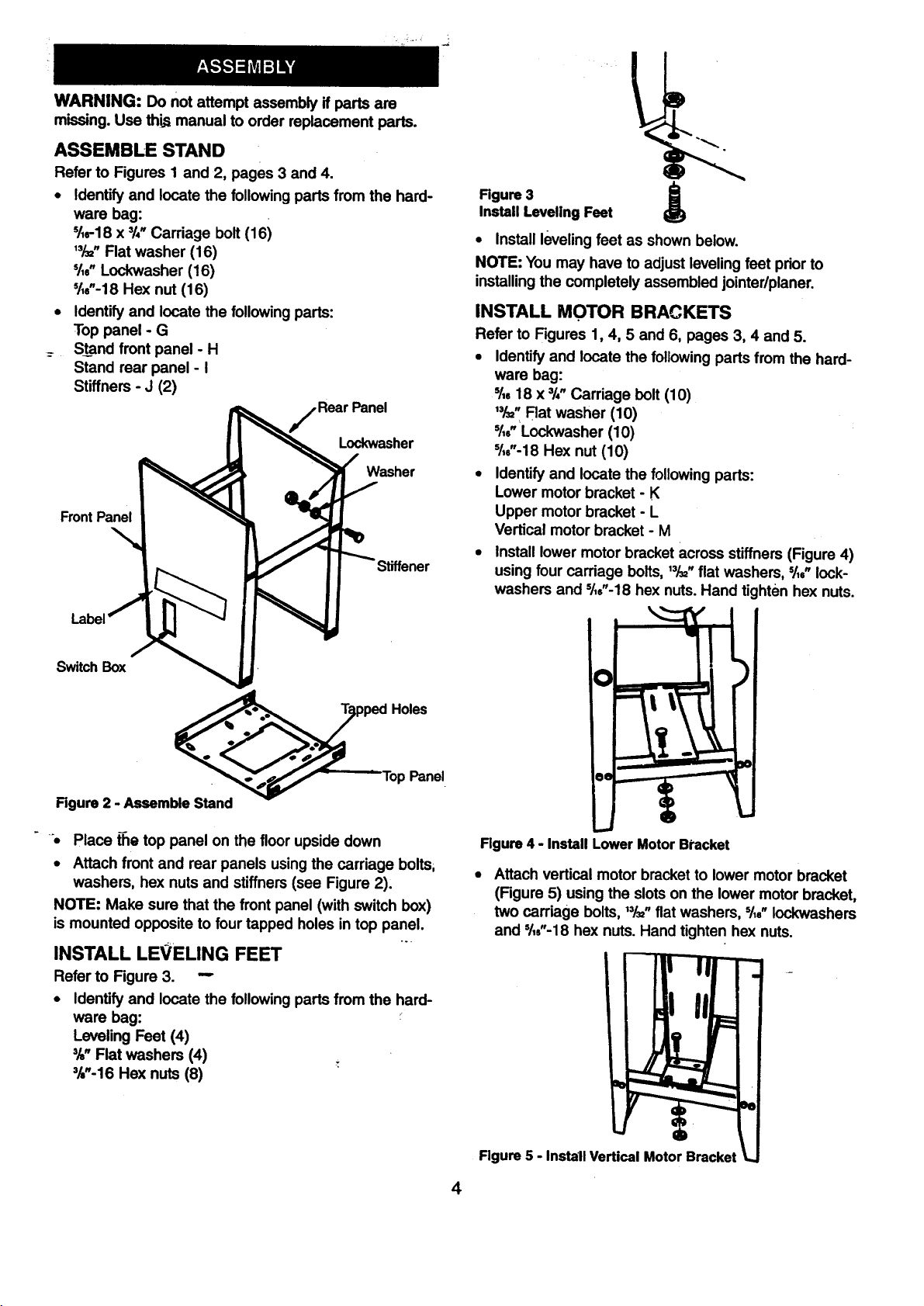
ASSEMBLE STAND
Refer to Figures I and 2, pages 3 and 4.
• Identify and locate the followingparts from the hard-
ware bag:
%-18 x 3/4.Carriage bolt (16)
,3/=. Flat washer (16)
%" Lockwasher (16)
51,6"-18Hex nut (16)
• Identify and locate the following parts:
Top panel ° G
_ Stand front panel - H
Stand rear panel - I
Stiffners - J (2)
Panel
Lockwasher
Washer
FrontPanel
Rgure 3
Install Leveling Feet
• Install leveling feet as shown below.
NOTE: You may have to adjust leveling feet priorto
installingthe completely assembled jointer/planer.
INSTALL MOTOR BRACKETS
Refer to Figures 1, 4, 5 and 6, pages 3, 4 and 5.
• Identify and locate the followingparts from the hard-
ware bag:
% 18 x 3/,"Carriage bolt (10)
,3/=. Rat washer (10)
'/=" Lockwasher (10)
s/,6"-18Hex nut (10)
• Identify and locate the followingparts:
Lower motor bracket - K
Upper motor bracket - L
Vertical motor bracket - M
• Install lower motor bracket across stiffners (Figure 4)
using four carriage bolts, ,3/=,flat washers, %" lock-
washers and 5/,6"-18hex nuts.Hand tighten hex nuts.
Switch Box
ped Holes
' Top Panel
Rgure 2 - Assemble Stand
_- Place the top panel on the floor upside down
• Attach front and rear panels usingthe carriage bolts,
washers, hex nuts and stiffners (see Figure 2).
NOTE: Make sure that the front panel (with switchbox)
is mounted opposite to four tapped holes in top panel.
INSTALL LEVELING FEET
Refer to Figure 3. -"
• Identify and locate the following parts from the hard-
ware bag: :
Leveling Feet (4)
3/s"Flat washers (4)
3/,"-16Hex nuts (8)
Figure 4 - Install Lower Motor Bracket
Attach vertical motor bracket to lower motor bracket
(Figure 5) using the slots on the lower motor bracket,
two carriage bolts,,3/=, flat washers, %" Iockwashers
and 3113"-18hex nuts. Hand tighten hex nuts.
Figure 5 - Install Vertical Motor Bracket
4
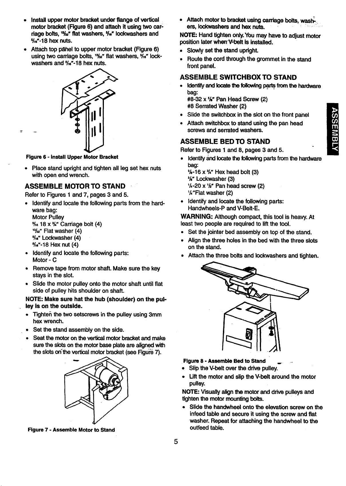
• Install upper motor bracket under flange of vertical
motor bracket (Figure 6) and attach it using two car-
dage bolts, "/=_'fiat washers, =/_,"Iockwashers and
s/,,'-18 hex nuts.
. Attach top pahel to upper motor bracket (Figure 6)
using twocarriage bolts, '¥=" fiat washers, '/,," lock-
washers and %"-18 he)( nuts.
Rgure 6 - Install Upper Motor Bracket
• Place stand upright and tighten all leg set hex nuts
with open end wrench.
ASSEMBLE MOTOR TO STAND
Refer to Figures 1 and 7, pages 3 and 5.
• Identify and locate the following parts from the hard-
ware bag:
Motor Pulley
Sl, 18 x 31,"Carriage bolt (4)
"/3="Flat washer (4)
Sl,..Lockwasher (4)
'/,.'-18 Hex nut (4)
• Identify and locate the following parts:
Motor - C
• Remove tape from motor shaft. Make sure the key
stays in the slot.
• Slide the motor pulley onto the motor shaft untilflat
side of pulley hits shoulder on shaft.
NOTE: Make sure hat the hub (shoulder) on the pul-
ley Is on the outside.
• Tighte_ the two setscrews inthe pulley using 3mm
hex wrench,
• Set the stand assembly on the side.
• Seat the motoron the vertical motorbracket and make
surethe slotson the motorbase plate are aligned with
the slotson'the verticalmotor bracket (see Figu;'_7).
Rgure 7 - Assemble Motor to Stand
• Attach motor to bracket using cardage bolts, wash_-
ers, IodoNashersand hex nuts.
NOTE: Hand tighten only.You may have to adjust motor
position later when-V=belt is installed.
• Slowly set the stand upright.
• Route the cord through the grommet in the stand
front panel.
ASSEMBLE SWlTCHBOX TO STAND
• Identifyand locate the following_ fromthe hardware
bag:
#8-32 x s/=.Pan Head Screw (2)
#8 Serrated Washer (2)
• Slide the switchboxin the slot on the front panel
• Attach switchboxto stand using the pan head
screws and serrated washers.
ASSEMBLE BED TO STAND
Refer to Figures 1 and 8, pages 3 and 5.
• Identify_ locatethe followingpartsfrom the hardware
bag:
3/8-16x 3/,, Hex head bolt (3)
%" Lockwasher (3)
'/,-20 x '/="Pan head screw (2)
'/,"Flat washer (2)
• Identify and locate the following parts:
Handwheels-P and V-Belt-E,
WARNING: Although compact, this tool is heavy. At
least two people are required to liftthe tool.
Set the jointer bed assembly on top of the stand.
• Align the three holes in the bed with the three slots
on the stand.
• Attach the three bolts and Iockwashers and tighten.
Figure 8 - Assemble Bed to Stand
• Slip the V-belt over the drive pulley.
• Liftthe motor and slip the V-belt around the motor
pulley.
NOTE: Visually align the motor and drive pulleys and
tighten the motor mounting bolts.
• Slide the handwheel onto the elevation screw on the
infeed table and secure it using the screw and flat
washer. Repeat for attaching the handwheel to the
ouffeed table.
5
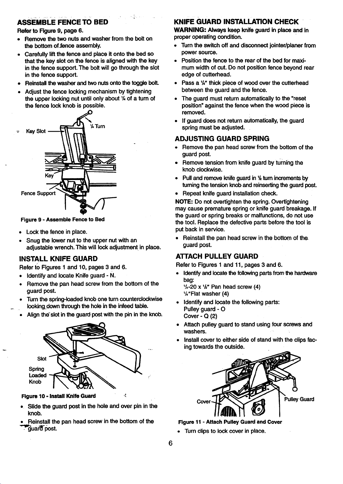
ASSEMBLE FENCE TO BED
Refer to Rgure 9, page 6.
• Remove the two nuts and washer from the bolt on
the bottom of.fence assembly.
• Carefully lift the fence and place it onto the bed so
that the key slot on the fence is aligned with the key
in the fence support. The boltwill go through the slot
in the fence support.
• Reinstall the washer and two nutsonto the toggle bolt.
• Adjust the fence locking mechanism by tightening
the upper locking nut until only about 1/,of a tum of
the fence lock knob is possible.
'/, Turn
-- Key Slot
Fence Support
Figure 9 - Assemble Fence to Bed
• Lock the fence in place.
• Snug the lower nut to the upper nutwith an
adjustable wrench. This will lock adjustment in place.
INSTALL KNIFE GUARD
Refer to Figures 1 and 10, pages 3 and 6.
• Identify and locate Knife guard - N.
• Remove the pan head screw from the bottom of the
guard post.
• Turn the spring-loadedknob one turn counterclockwise
Iookingdown throughthe holein the infeed table.
• Align the-slot in the guard postwith the pin in the knob.
KNIFE GUARD INSTALLATION CHECK
WARNING: Always keep knife guard in place and in
proper operating condition.
• Turn the switch off and disconnect jointer/planer from
power source.
• Positionthe fence to the rear of the bed for maXi-
mum width of cut. Do not position fence beyond rear
edge of cutterhead.
• Pass a '/," thick piece of wood overthe cutterhead
between the guard and the fence.
• The guard must return automatically to the "reset
position"against the fence when the wood piece is
removed.
• If guard does not return automatically,the guard
spring must be adjusted.
ADJUSTING GUARD SPRING
• Remove the pan head screw from the bottom of the
guard post.
• Remove tension from knife guard by turning the
knob clockwise.
• Pulland remove knifeguard in '/=turnincrementsby
turningthe tension knoband reinsertingthe guard post.
• Repeat knife guard installationcheck.
NOTE: Do not overtighten the spring. Overtightening
may cause premature spring or knifeguard breakage. If
the guard or spring breaks or malfunctions, do not use
the tool. Replace the defective parts before the tool is
put back inservice.
• Reinstall the pan head screw inthe bottom of the
guard post.
A'I-I'ACH PULLEY GUARD
Refer to Figures 1 and 11, pages 3 and 6.
• Identifyand locatethe following partsfromthe hardware
bag:
V,-20 x '/="Pan head screw (4)
V4"Flatwasher (4)
• Identify and locate the following parts:
Pulley guard - 0
Cover - Q (2)
• Attach pulley guard to stand using four screws and
washers.
• Install cover to either side of stand with the clips fac-
ing towards the outside.
Slot
Spdng
Loaded
Knob
Figure 10 - Install Knife Guard
, Slide the guard post in the hole and over pin in the
knob.
• Reinstall the pan head screw in the bottom of the
._uar=_-i::)ost.
Cover uard
Rgure 11 - Attach Pulley Guard and Cover
• Turn clips to lock cover in place.
6
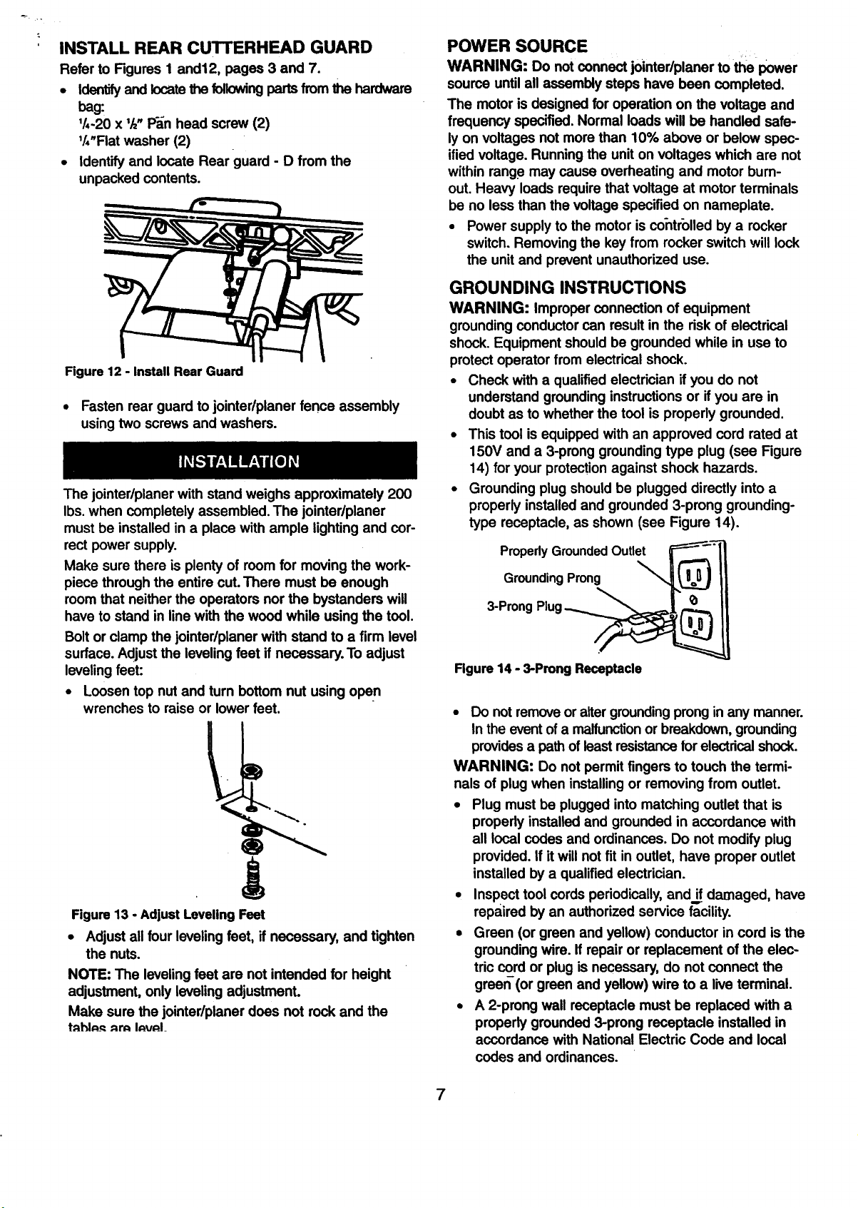
INSTALL REAR CUTTERHEAD GUARD
Refer to Figures I and12, pages 3 and 7.
• Identifyand locatethe followingparts from the hardware
bag:
'/,-20 x 'h" PEn head screw (2)
'/,'Flat washer (2)
• Identify and locate Rear guard - D from the
unpacked contents.
Figure 12 - Install Rear Guard
• Fasten rear guard to jointedplaner fence assembly
using two screws and washers.
The jointer/planer with stand weighs approximately 200
Ibs. when completely assembled. The jointer/planer
must be installed in a place with ample lighting and cor-
rect power supply.
Make sure there is plenty of room for moving the work-
piece through the entire cut. There must be enough
room that neitherthe operators nor the bystanders will
have to stand in line with the wood while using the tool.
Bolt or clamp the jointedplaner with stand to a firm level
surface. Adjust the leveling feet if necessary. To adjust
leveling feet:
• Loosen top nut and turn bottom nut using open
wrenches to raise or lower feet.
Figure 13 - Adjust Leveling Feet
• Adjust all four leveling feet, if necessary, and tighten
the nuts.
NOTE: The leveling feet are not intended for height
adjustment, only leveling adjustment.
Make sure the jointer/planer does not rock and the
tAhlA._ArA IAVAI_
POWER SOURCE
WARNING: Do notconnect jointer/planer to the power
source until all assembly steps have been completed.
The motor is designed for operation on the voltage and
frequency specified. Normal loads will be handled safe-
ly on voltages not more than 10% above or below spec-
ified voltage. Running the unit on voltages which are not
within range may cause overheating and motor burn-
out. Heavy loads require that voltage at motor terminals
be no less than the voltage specified on nameplate.
• Power supply to the motor is co-ntr'olledby a rocker
switch. Removing the key from rocker switch will lock
the unit and prevent unauthorized use.
GROUNDING INSTRUCTIONS
WARNING: Improper connection of equipment
grounding conductor can result in the dsk of electrical
shock. Equipment should be grounded while in use to
protect operator from electrical shock.
• Check with a qualified electrician if you do not
understand groundinginstructions or if you are in
doubt as to whether the tool is properly grounded.
• This tool is equipped with an approved cord rated at
150V and a 3-prong grounding type plug (see Figure
14) for your protectionagainst shock hazards.
• Grounding plug should be plugged directly into a
properly installed and grounded 3-prong grounding-
type receptacle, as shown (see Figure 14).
PropedyGroundedOutlet
GroundingProng
3-Prong
Figure14 - 3-Prong Receptacle
• Do not removeor altergroundingprong in any manner.
In the event of a malfunctionor breakdown, grounding
providesa pathof least resistancefor electrical shock.
WARNING: Do not permit fingers to touch the termi-
nals of plugwhen installingor removing from outlet.
• Plug must be plugged into matching outlet that is
propedy installed and grounded in accordance with
all local codes and ordinances. Do not modify plug
provided. If it will not fit in outlet, have proper outlet
installed by a qualified electrician.
• Inspect tool cords periodically, andif damaged, have
repaired by an authorized service facility.
• Green (or green and yellow) conductor in cord is the
grounding wire. If repair or replacement of the elec-
tric cord or plug is necessary, do not connect the
greer_'(orgreen and yellow) wire to a live terminal.
• A 2-prong wall receptacle must be replaced with a
properly grounded 3-prong receptacle installed in
accordance with National Electric Code and local
codes and ordinances.
7
WARNING: Any receptacle replacement s_uid be _
performed by a qualified electrician.
A temporary 3-prong to 2-prong groundingadapter (see
Figure 15) is available for connecting plugsto a two
pole outlet if it_s-properly grounded.
GroundingLug MakeSureThis
3-Prong To A Known
Rgure 15 - 2-Prong Receptacle with Adapter
• Do not use a 3-prong to 2-prong grounding adapter
unless permitted by localand national codes and
--- Ordinances. (A 3-prong to 2-prong grounding adapter
is not permitted inCanada.)
Where a 3-prong to 2-prong groundingadapter is
permitted, the rigid green tab or terminal on the side
of the adapter must be securely connected to a
permanent electrical ground such as a properly
grounded water pipe, a properly grounded outlet box
or a properly grounded wire system.
• Many cover plate screws, water pipes and outlet
boxes are not properly grounded.To ensure proper
ground, grounding means must be tested by a quali-
fied electrician.
EXTENSION CORDS
• The use of any extension cord will cause some drop
in voltage and loss of power.
• Wires of the extension cord must be of sufficient size
to carry the current and maintain adequate voltage.
• Use the table to determine the minimum wire size
(A.W.G.) extension cord.
• Use only 3-wire extension cords having 3-prong
grounding type plugs and 3-pole receptacles which
accept the tool plug.
• If the extension cord is worn, cut or damaged inany
way, replace it immediately.
EXTENSION CORD LENGTH
Wire Size A.W.G.
Upto 50 ft................................ 16
50-100 ft.................................. 14
NOTE: Using extension cords over 100 ft. long is not
recommended. .-.-
Is Connected
Ground
2-Prong Receptacle
MOTOR
Jointer/planer is supplied with a 2 HP (max developed)
motor.
The 120 Volt AC universal motor has the:following
specifications:
Horsepower (Maximum Developed) .............. 2
Voltage .... : ............................ 120
_e re_.. .............................. 10.8
Hertz.. i....:.:.... _:,i... ..... .... !.. :,._60
Phase ....... ......................... Single
RPM .................................. 5000
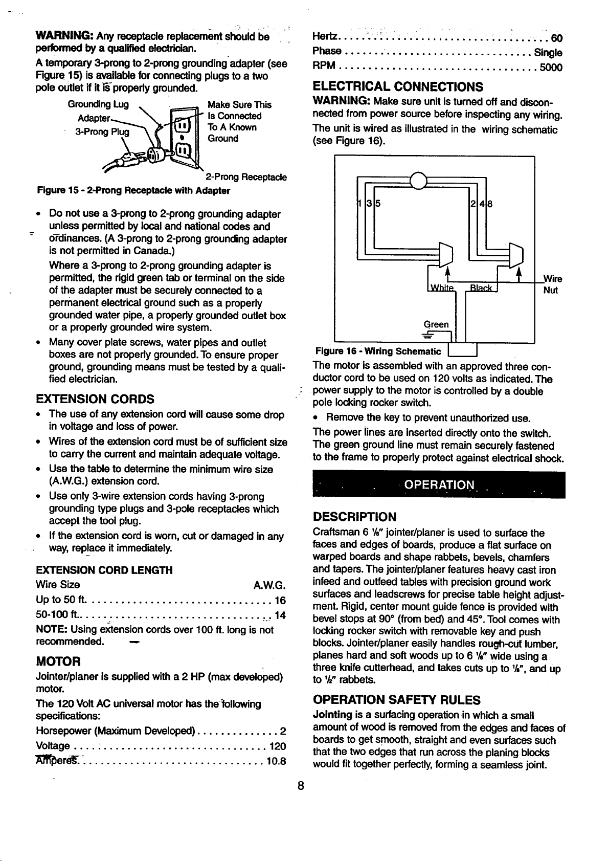
ELECTRICAL CONNECTIONS
WARNING: Make sure unit is turned off and discon-
nected from power source before inspecting any wiring.
The unit iswired as illustratedin the wiring schematic
(see Figure 16).
]31° ]28
Wire
Nut
Figure 16 ' WiringSchematic I I
The motor is assembled with an approved three con-
ductor cord to be used on 120 volts as indicated.The
power supply to the motor is controlled by a double
pole locking rocker switch.
• Remove the key to prevent unauthorized use.
The power lines are inserted directly onto the switch.
The green ground line must remain securely fastened
to the frame to propedy protect against electrical shock.
DESCRIPTION
Craftsman 6 %" jointer/planer is used to surface the
faces and edges of boards, produce a fiat surface on
warped boards and shape rabbets, bevels, chamfers
and tapers. The jointer/planer features heavy cast iron
infeed and outfeed tables with precisionground work
surfaces and leadscrews for precise table height adjust-
ment. Rigid, center mount guide fence is provided with
bevel stops at 90° (from bed) and 45°.Tool comes with
locking rocker switch with removable key and push
blocks.Jointer/planer easily handles rough-cut lumber,
planes hard and soft woods up to 6 %" wide using a
three knife cutterhead, and takes cuts up to l/s",and up
to 1/=,rabbets.
OPERATION SAFETY RULES
Jointing is a surfacingoperationin which a small
amount of wood is removed from the edges and faces of
boards to get smooth, straightand even surfaces such
that the two edges that runacross the planing blocks
would fit together perfectly,forming a seamless joint.
8
 Loading...