

Craftsman 351226712 Owner’s Manual

SAVE THIS MANUAL
FOR
FUTURE REFERENCE
OWNER'S
MANUAL
MODEL NO.
351.226712
/£RRFrSHRN®
l x 6" Belt & Disc Sander
CAUTION:
READ ALL
INSTRUCTIONS
CAREFULLY!
Sold by SEARS, ROEBUCK AND CO., Chicago, IL 60684 U.S.A. ©
Part No. 3899.01 AUGUST 1993
• safety instructions
= operating instructions
• replacement parts

FULL ONE YEAR WARRANTY ON SEARS/CRAFTSMAN 1x 6" BELT & DISC SANDER
if within one full year from tile date of purchase, this Sears Craftsman 1x 6" Belt & Disc Sander fails due to a
defect in material or workmanship, Sears will repair it, free of charge.
WARRANTY SERVICE iS AVAILABLE BY SIMPLY CONTACTING THE NEAREST SEARS STORE OR SERVICE
CENTER THROUGHOUT THE UNITED STATES.
This warranty gives you specific legal rights, and you may have other rights whictl vary from state to state,
SEARS, ROEBUCK AND CO., D817/WA, HOFFMAN ESTATES, IL 60179
GENERAL SAFETY INSTRUCTIONS FOR POWER TOOLS
BEFORE ANY WORK IS DONE READ THE CAUTIONS
LISTED BELOW CAREFULLY, WORKING SAFELY
PREVENTS ACCIDENTS,
OPERATOR SHOULD BE PREPARED FOR JOB:
a+ Wear proper apparel+ Do not wear loose clothing,
gloves, neckties, rings, bracelets or other jewelry
which may get caught in moving parts of machine
b. Wear protective hair covering to contain long hair.
c Wear safety shoeswith non-slip soles+
d.. Wear safety glasses+ Everyday glasses have only
impact resistant lenses+They are not safety glasses
e. Wear face mask or dust mask if sanding operation
isdusty+
f Be alert and think clearly. Never operate power
tools when tired, intoxicated or when taking med-
ications that cause drowsiness.
WORK AREA SHOULD BE READY FOR JOB:
a+ Keep work area clean+ Cluttered work areas and
workbenches invite accidents,,
b+ Do not use power tools in dangerous environ-
merits+ Do not use power' tools in damp or. wet
locations. Do not expose power tools to rain.
c+ Work area should be properly lighted.
d+ Proper electrical outlet should beavailablefortooL
Three-prong plug should be plugged directly into
properly grounded, three-prong receptacle+
e+ Extension cords should have a grounding prong
and the three wires of the extension cord should be
the correct gauge+
f+ Keep visitors a safe distance from work area+
g+ Keep children out of workplace+ Make workshop
child-proof. Use padlocks, master' switches and
remove starter' keys to prevent any unintentional use
of power tools,
TOOL SHOULD BE MAINTAINED:
a+ Always unplug power tool prior,to inspection.
b+ Consult owner's manual for specific maintainirlg
and adjusting pr.ocedureso
c+ Use clean belts and keep the tool clean for safest
operation+
d. Remove adjusting keys and wrenches. Form
habit of checking to see that keys and adjusting
wrenches are removed before turning tool on.
e+ Keep all guards in place and in workingorder.
f+ Keep all parts in working order. Check to deter-
mine that the guard or other parts will operate
propedy and perform their' intendedfunction+
g Check for damaged parts+ Check for atignment of
moving parts, binding of moving parts, breakage of
parts, mounting and any other condition that may
affect a tool's operation
h+ A guard or other part that is damaged should be
properly repaired or replaced. Do not perform
makeshift repairs_ (Use the parts list provided to
+ order replacement parts+)
OPERATOR SHOULD KNOW HOW TO USE TOOL:
a+ Use right tool for the job. Do not force tool or'
attachment to do a job for which it was not de+
signed.
b. Disconnect tool when changing accessories,
such as belt, disc, miter gauge and the like.
c Avoid accidental start-up. Make sure that the
machine is in the "off" position before plugging in+
d° Do not force a tool It will work most efficiently at
the rate for which it was designed
e+ Use recommended accessories, Referto page 11.
Use of improper accessories may cause risk of injury
to persons
f+ Handle the workpiece correctly. Use m_tergauge
when required, Protect hands from possibleinjury+
g+ Direction of feed. Feed work into a belt or disc
against direction of rotation of the belt or+disc.
h+ Turn the machine off if it jams. Disconnect plug
from power' source before servicing tool.,
L Never leave a tool running unattended+ Turn the
power off and do not leave sander until it comes to
a complete stop+
j+ Do not overreach. Keep proper footing and
balance,
k+ Never stand on tool Serious injury could occur if
tool is tipped or'if abrasive belt or disc is unintention-
ally contacted+
I+ Keep hands away from moving parts and sanding
surfaces+
m+ Know your power tool. Learn itsoperation, applica-
tion and specific limitations+
-2-

CONTENTS
Warranty ................................ 2
General Safety Instructions
for Power Tools ...................... 2
Safety Instructions
for Belt & Disc Sander ................. 3
Motor Specifications
and Electrical Requirements ............ 4
Electrical Connections .................. 4 & 5
WARNING LABEL
The belt and disc sander has been marked with awarning
label that needs to be observed for safe operation. The
operator should be aware of the location and contents
of thts label
WARNING
FOR SAFE OPERATION SEE OWNER'S MANUAL
1_ Always wear safety gog_le_ complying with ANSI Z871
II When soMctng use anty Identlca, I replacement pads
M Suppottwo;kplecewIlhbacksloporwoTklable
H Maintain 1116" max clearance beM,een table and sanding belt ot d_ec
Im Mount securely to workbench
SAFETY INSTRUCTIONS FOR
Unpacking and Checking Contents ........... 5
Tools Needed ............................ 5
Assembly ............................... 6
Operation ............................... 6
Maintenance .......................... 8 & 9
Trouble Shooting ......................... 9
Replacement Parts Illustration .............. 10
Replacement Parts List .................... 11
This warning label is placed in a specific location so it is
visible to the operator when starting and operating the
belt and disc sander.
l"x 6" BELT & DISC SANDER
WARNING: DO NOT ATTEMPT TO OPERATE BELT
& DISC SANDER UNTIL IT IS COM-
PLETELY ASSEMBLED ACCORDING
TO THE INSTRUCTIONS.
t Know general power tool safety, Make sure all
precautions are understood and provlded for (page
2. Secure all fasteners. Frequently check that nuts
and bolts are tight and have not vibrated loose,
3. Follow operation instructions. Operate the belt
and disc sander as described in this manual (pages
6 through 8).
4,, Be sure motor runs clockwise on disc side.
Abrasive belt must traveldown
,,
Perform disc sanding on down side (rightside).
The disc should pull work towards the table°
6_
Support workpiece. Use backstop or work table
The backstop for the abrasive belt isthe belt platen
(Key No. 25) as described in "Operating Instruc-
tions" (page 7),,
,
Do not force work° Slowing or stalling the motor
will overheat it,
8_
Do not overheat work. Move metal across the
abrasive and cool itwhen itbecomes hot.
9,
Do not wet grind or polish. Never use a steady
stream of water on the workpieceo Only quench the
workpiece in water to cool it.
10o Do not grind or polish magnesium. Itcould catch
on fire.
11_ Keep sander maintained. Follow "Maintenance
instructions" (page 9).
12 Disconnect power, Turn :switch off and disconnect
power whenever sander is not in use.
CAUTION: Be certain to follow proper operating
procedures despite familiarity gained
from frequent use of your belt and disc
sander. Always remember that being
careless for even a fraction of a second
is sufficient time to inflict severe injury.
The operation of any power tool can result In foreign
objects being thrown into the eyes, which can result in
severe eye damage,
Always wear safety goggles complying with ANSI Z87ot
(shown on package) before commencing power tool
operation° Safety goggles are available at Sears retail or
catalog stores.
THINK SAFETY: Safety is a combination of operator
common sense and alertness at alt
times when the belt & disc sander is
being used_
-3-
MOTOR SPECIFICATIONS AND ELECTRICAL REQUIREMENTS
PROPERLY
GROUNDED
MOTOR
The belt and disc sander is assembled with motor and
wiring insta!led as an integral part of the tool..
The 120 Volt AC permanent split capacitor motor' has the
following specifications:
Max..Developed Horsepower ...................... 1/2
Voltage ................................................. 120
Amperes .............................................. 4
Hertz .............................................. 60
Phase ...........................................Single
RPM ..........................................3450
Rotation(viewedfromleftside)..........Clockwise
POWER SOURCE
CAUTION: Do not connect the belt and disc sander
to the power source until all assembly
steps have been completedo
1. The motor is designed for operation on the voltage
and frequency specified on motor nameptatev
2_ Normal loads will be handled safely on voltages not
more than 10% above or below nameplate voltage.
3. Running the unit on voltages which are not within
range may cause overheating and motor-burn-ouL
4. Heavy loads require that voltage at motor terminals
be not lessthan voltage specified on nameplate.
GROUNDING INSTRUCTIONS
This tool is equipped with a 3-conductor cord and
ground type plug which has a grounding prong ap-
proved by Underwriters Laboratories and the Canadian
Standards Association.
Do not remove or' alter' the grounding prong in any
manner° In the event of a malfunction or breakdown,
grounding provides a path of least resistance for electri-
cal current to reduce the risk of electrical shock
The plug must be plugged into a matching outlet that is
properly installed and grounded in accordance with all
local codes and ordinances,.
Do not modify the plug provided° If it will not fit In the
outlet, have the proper' outlet installed by a qualified
electrictan_ improper connection of equipment-ground-
ing conductor can result in a rlsk of electrical shock.
The conductor with insulation having an outer surface
which is green tsthe equipment grounding conductor.
If repair or replacement of the electrical cord or plug is
necessary, make sure the equipment grounding con-
ductor is not connected to a line terminal.
WARNING: CHECK WITH A QUALIFIED ELECTRI-
CIAN OR SERVICE PERSONNEL IF THE
GROUNDING INSTRUCTIONS ARE NOT
UNDERSTOOD OR IF IN DOUBT AS TO
WHETHER TOOL IS PROPERLY
GROUNDED,
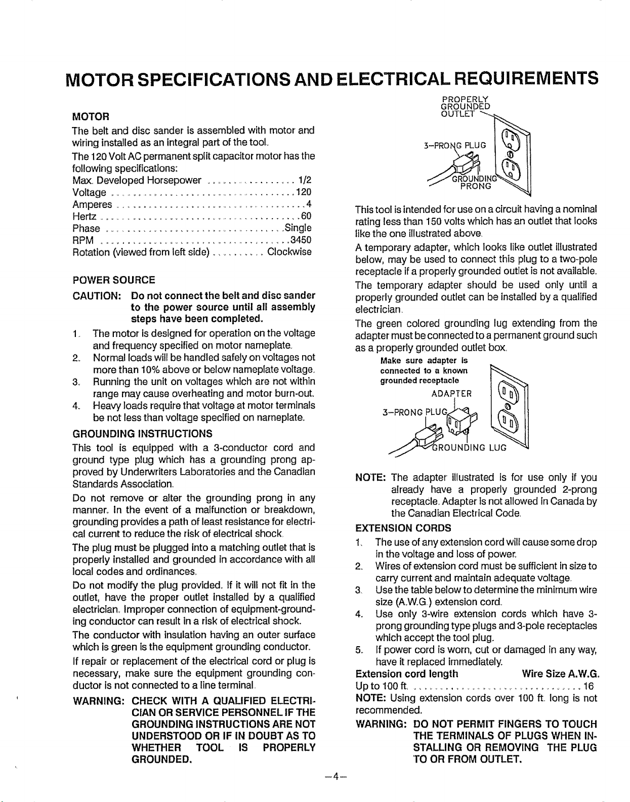
This toot is intended for'use on a circuit having a nominal
rating tess than I50 volts which has an outlet that looks
tike the one illustrated above.
A temporary adapter', which looks like outlet illustrated
below, may be used to connect this plug to a two-pole
receptacle if a properly grounded outlet isnot available.
The temporary adapter should be used only until a
properly grounded outlet can be installed by a qualified
electrician,
The green colored grounding lug extending from the
adapter must be connected to a permanent ground such
as a properly grounded outlet box.
Make sure adapter ts
connectedto a known
grounded receptacle
3-PRONG PLUG_
NOTE: The adapter illustrated is for use onIy if you
already have a properly grounded 2-prong
receptacle. Adapter ts not allowed in Canada by
the Canadian Electrical Code.
EXTENSION CORDS
1_ The use of any extension cord wilt cause some drop
in the voltage and loss of power.
2. Wires of extension cord must be sufficient in size to
carry current and maintain adequate voltage
3, Use the table below to determine the minimum wire
size (A.W.G) extension cord°
4. Use only 3-wire extension cords which have 3-
prong grounding type plugs and 3-pole receptacles
which accept the tool plug.
5. If power cord is worn, cut or damaged in any way,
have it replaced immediately.
Extension cord length Wire Size A.W.Go
Upto 100ft ..............................................16
NOTE: Using extensioncords over'100 ft.,longisnot
recommended°
WARNING: DO NOT PERMIT FINGERS TO TOUCH
-4-
OUTLET "_
"" PRONG "_
ADAPTER
THE TERMINALS OF PLUGS WHEN IN-
STALLING OR REMOVING THE PLUG
TO OR FROM OUTLET.
 Loading...