

Craftsman 351226321, 35122632 Owner’s Manual

MANUAL,
MODEL N@o
351 °22532
and MITER
CAUTION:
READ ALL
gNSTRUCTgONS
CAREFULLy!
i . i,,
Sold by SEARS, ROEBUCK AND CO., Chicago, 0L60684 U.S.A.
Part No, 138000 Copyrighted
oassembly'
ooperating
, repair parts

FULL ONE YEAR WARRANTY ON SEARS CRAFTSMAN
If within one year from the date of purchase, this Sears Craftsman Belt & Disc Sander fails due
_=< to a defect in material or workmanship, Sears will repair it, free of charge
WARRANTY SERVICE IS AVAILABLE BY SIMPLY CONTACTING THE NEAREST SEARS ==_
c_<
STORE OR SERVICE CENTER THROUGHOUT THE UNITED STATES.
This warranty gives you specific legal rights, and you may also have other rights which vary from
state to state.
SEARS, ROEBUCK AND CO., DEPT.698/731A SEARS TOWER, CHICAGO, IL 60684
GENERAL SAFETY INSTRUCTIONS FOR POWER TOOLS
BEFORE ANY WORK IS DONE, READ THE
CAUTIONS LISTED BELOW CAREFULLY.
WORKING SAFELY PREVENTS ACCIDENTS°
1 OPERATOR SHOULD BE PREPARED FOR THE
JOB:
a Do not wear loose clothing, jewelry or gloves
that will get caught in moving parts of the
machine_
b, Wear safety shoes with non-slip soles.
c Wear safety glasses.
d. Wear face mask or dust mask when needed.
e. Be alert, and think clearly.
f. Never operate power tools when tired,
intoxicated, or when taking medications that
cause drowsiness.
2. WORK AREA SHOULD BE READY FOR THE JOB:
a, An uncluttered work area ensures that the oper-
ator has ample room for movement and place-
ment of the work_ Clean floors ensure good
footing
b, Environment should be suitable for tool; Power
tools should not be used in damp locations, or
gaseous, explosive atmospheres.
c. Area should be properly lighted_
d Proper electrical outlet should be available for
the tool.
1. Three-prong plug should be plugged directly
into a properly grounded three-prong
receptacle
2. If work area is not grounded, a qualified elec-
trician should install the proper electrical
system.
e_ Extension cords should have a grounding prong,
and the three wires of the extension cord should
be the correct gauge.
f Keep visitors a safe distance away from work
area_
3 TOOL SHOULD BE MAINTAINED:
a. Always unplug power tool prior to inspection
or maintenance.
b. Consult the owner's manual for specific main-
taining and adjusting procedures,
c, Keep machine lubricated
d. Use sharp blades, and keep the tool clean for
best, and safest operation,
e. Never leave adjusting keys and wrenches on
machine; remove them
L Workbed of power tool should only be used to
support the workpiece and necessary
accessories_
g Use recommended accessories only, and follow
manufacturer's instructions.
h, Keep all guards in place.
i Keep all parts in working order; do not perform
makeshift repairs (Use the Parts List provided
with the owner's manual to order replacement
parts.)
j. Make sure the machine is mounted correctly;
never attempt to stabilize a floor or benchtop tool
by standing on it, or by holding it in position
4, OPERATOR SHOULD KNOW HOW TO USE THE
TOOL:
a_
Use the right tool for the job.
b.
Avoid accidental start-up; make sure that the
machine is in the OFF position before plugging
it in.
c Do not force a tool; it will work most efficiently
at the rate for which it was designed
d. Turn the machine OFF if it jams: A blade jams
when it digs too deeply into the work. (The motor
force keeps it stuck in the work.)
e. Handle the work piece correctly.
1. Secure the work with clamps, or a vise when-
ever possible; leave hands free to operate the
machine
2 Use push sticks or push blockswhen required;
protect hands from possible injury.
f Do not overreach: Keep the proper footing and
balance_
g. Keep hands away from moving parts and cutting
surfaces
h Know your power tool: learn its operation,
applications and specific limitations.

CONTENTS
Warranty ......................................................... 2
General Safety Instructions
for Power Tools ........................................ 2
Safety Instructions
for Belt & Disc Sander ............................... 3
Motor Specifications
and Electrical Requirements ....................... 4
Electrical Connections ..................................... 5
Unpacking and Checking Contents ................... 5
Tools Needed .................................................. 6
Assembly ........................................................ 6
Operation ........................................................ 8
Maintenance ................................................. 10
Trouble Shooting ........................................... 11
Replacement Parts List.................................. 12
Replacement Parts Illustration ........................ 14
SAFETY BNSTRUCTnONS FOR l in. BELT & 8in. DiSC SANDER
WARN|NG-" DO NOT ATTEMPT TO OPERATE
BELT & DISC SANDER UNTIL IT IS COMPLETELY
ASSEMBLED ACCORDING TO THE INSTRUCTIONS.
1 KNOW GENERAL POWER TOOL SAFETY. Make
sure all precautions are understood and provided
for (page 2)
2 SECURE ALL FASTENERS, Frequently check
that nuts and bolts are tight and have not vibrated
loose
3 FOLLOW OPERATION INSTRUCTIONS. Operate
the belt and disc sander as described in this
manual (page 8)
4 BE SURE MOTOR RUNS CLOCKWISE. Abrasive
belt must travel down
5 DISC SAND ON DOWN SIDE (RIGHT SIDE). The
disc should pull work towards the table_
11. KEEP SANDER MAINTAINED. Follow
maintenance instuctions (page 10)
12. DISCONNECT POWER, Turn switch "off" and
diconnect the power whenever sander is not be-
ing used
CAUTION: DO NOT ALLOW FAMILIARITY (GAINED)
FROM FREQUENT USE OF YOUR BELT AND DISC
SANDER TO BECOME COMMONPLACE ALWAYS
REMEMBER THAT A CARELESS FRACTION OF A
SECOND IS SUFFICIENT TO INFLICT SEVERE
INJURY
The operation of any power tool can result in foreign
objects being thrown into the eyes. which can result
in severe eye damage. Always wear safety goggles
complying with ANSI Z87.1 (shown on package) before
commencing power tool operation Safety Goggles are
available at Sears retail or catalog stores
6 SUPPORT WORKPIECE. Maintain control of
workpiece at all times
7. DO NOT FORCE WORK, Slowing or stalling the
motor will overheat it
8, DO NOT OVERHEAT WORK_ Move metal across
the abrasive and cool it when it becomes hot
9 DO NOT WET GRIND OR POLISH. Never use a
steady stream of water on the workpiece Only
quench the workpiece in water to cool it,
10 DO NOT GRIND OR POLISH MAGNESIUM. It
could catch on fire
THINK SAFETY: Safety is a combination of operator
common sense and alertness at all times when the Belt
& Disc Sander is being used.

MOTOR SPECIFICATOONS AND ELECTRICAL REQUIREMENTS
MOTOR
The Belt and Disc Sander is assembled with motor and
wiring installe&
The 120 Volt AC capacitor start motor has the follow-
ing specifications:
Horsepower ................................................................. 1/3
Voltage ................................................................. 120
Amperes .............,......................................................... 7
Hertz ......................................................................... 60
Phase ................................................................ Single
RPM .......................................................................... 1725
Rotation (viewed from pulley end) ............. clockwise
Frame size .................................................. NEMA 56Z
Use Sears Craftsman _912037C motor if a replace.
ment motor is needed
POWER SOURCE
CAUTION: DO NOT CONNECT THE BELT AND D)SC
SANDER TO ITS POWER SOURCE UNTIL ALL
ASSEMBLY STEPS HAVE BEEN COMPLETED
The motor is designed for operation on the voltage and
frequency specified on motor nameplate,
Normal loads will be handled safely on voltages not
more than 10% above or below the nameplate voltage.
Running the unit on voltages which are not within the
range may cause over-heating and motor burn-out
PROPERLY GROUNDED OUTLET
GROUNDING PRONG
3-PRONG PLUG
This unit is for use on less than 150V, it has a plug as
illustrated above.
If the outlet you are planning to use for this power tool
is of the two prong type, use an adapter as shown
below,
The green grounding lug extending from the adapter
must be connected to a permanent ground, such as
to a properly grounded outlet box.
Having a qualified electrician replace the two prong
outlet with a properly grounded three prong outlet is
recommended
GROUNDING LUG
A...... _ ;f=:_MAKE SURE THIS
u_r'rcn_ "_'_l IS CONNECTED
3-PRONGPLUG \ _ If_IITOAKNOWN
/."_"_'- "_"_ 2-PRONG
_" RECEPTACLE
NOTE: The adapter illustrated is for use only if you
already have a properly grounded 2-prong receptacle
Adapter is not allowed in Canada by the Canadian
Electrical Code.
EXTENSION CORDS
Heavy loads require that voltage at motor terminals be
not less than the voltage specified on narneplate,
This machine must be grounded while in use to pro-
tect the operator from electric shock
This power tool is equipped with a 3-conductor cord and
grounding type plug which has a grounding prong,
approved by Underwriters Laboratories and the
Canadian Standards Association,
Do not remove or alter the grounding prong in any
manner.
This plug requires a mating 3-conductor grounded type
outlet as shown.
Use a 110-120V properly grounded type outlet protect-
ed by a 15-amp. time delay fuse or circuit breaker
WARNaNG: BE SURE THAT THE OUTLET IS
PROPERLY GROUNDED, HAVEIT CHECKED BY A
QUALIFIED ELECTRICIAN°
The use of any extension cord will cause some drop
in the voltage and loss of power
The wires of the extension cord must be sufficient in
size to carry the current and maintain adequate voltage.
Use the table below to determine the minimum wire size
(A WG,) extension cord.
Use only 3 wire extension cords which have 3 prong
grounding type plugs and 3-pole' receptacles which
accept the tool plug
If power cord is worn; cut, or damaged in any way, have
it replaced immediately_
Extension cord Length Wire Size A.W.G.
Up to 50 ft ................................................................. 16
50 - 100 ft................................................................ 14
NOTE: Using extension cords over 100 fL long is not
recommended.
WARNBNG: DO NOT PERMIT FINGERS TO
TOUCH THE TERMINALS OF PLUGS WHEN IN-
STALLING OR REMOVING THE PLUG TO OR FROM
ELECTRICAL CONNECTIONS
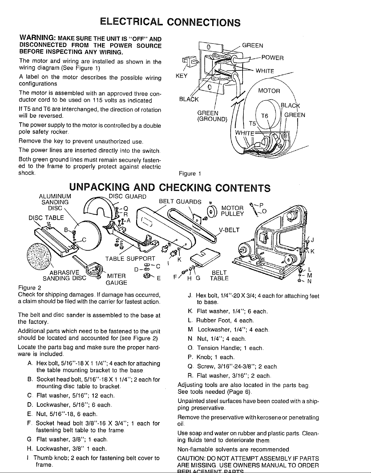
WARNING: MAKE SURE THE UNIT IS "OFF" AND
DISCONNECTED FROM THE POWER SOURCE
BEFORE INSPECTING ANY WIRING.
The motor and wiring are installed as shown in the
wiring diagram(See Figure 1)
A label on the motor describes the possible wiring
configurations
The motor is assembled with an approved three con-
ductor cord to be used on 115 volts as indicated
If T5 and T6 are interchanged, the direction of rotation
will be reversed
The power supply to the motor is controlled by a double
pole safety rocker
Remove the key to prevent unauthorized use_
The power lines are inserted directly into the switch.
Both green ground lines must remain securely fasten-
ed to the frame to properly protect against electric
shock
Figure 1
GREEN
(GROUND)
UNPACKING AND CHECKING CONTENTS
ALUMINUM DISC GUARD
SANDING BELT GUARDS
o,sc
DISC TABLE PULLEY
GREEN
_.-.----- POWER
WHITE
ILACK
1
GREEN
TABLE SUPPORT 114_...___4_"_)
ABRASIVE t£._ ..... u'- BELT L
SANDING DISC _ IVH/CH _"" E H G TABLE M
GAUGE N
Figure 2
Check for shipping damages If damage has occurred,
a claim should be filed with the carrier for fastest action.
The belt and disc sander is assembled to the base at
the factory.
Additional parts which need to be fastened to the unit
should be located and accounted for (see Figure 2)
Locate the parts bag and make sure the proper hard-
ware is included.
A Hex bolt, 5/16"-18 X 1 1/4"; 4 each for attaching
the table mounting bracket to the base
B. Socket head bolt, 5/16"-18 X 1 1/4"; 2 each for
mounting disc table to bracket.
C Flat washer, 5/16"; 12 each+
D Lockwasher, 5/16"; 6 each.
E Nut, 5/16"-18, 6 each
F Socket head bolt 3/8"-16 X 3/4"; 1 each for
fastening belt table to the frame
G Flat washer, 3/8"; 1 each.
H Lockwasher, 3/8" 1 each.
I Thumb knob; 2 each for fastening belt cover to
frame
V-BE LT _l i/'"_:"_'_'-_- I!_
J. Hex bolt, 1/4"-20 X 3/4; 4 each for attaching feet
to base.
K Flat washer, 1/4"; 6 each.
L. Rubber Foot, 4 each.
M Lockwasher, 1/4"; 4 each.
N. Nut, 1/4"; 4 each.
O. Tension Handle; 1 each_
P. Knob; 1 each.
Q. Screw, 3/16"-24-3/8"; 2 each
R. Flat washer, 3/16"; 2 each
Adjusting tools are also located in the parts bag
See tools needed (Page 6)
Unpainted steel surfaces have been coated with a ship-
ping preservative.
Remove the preservative with kerosene or penetrating
oil.
Use soap and water on rubber and plastic parts Clean-
ing fluids tend to deteriorate them
Non41amable solvents are recommended
CAUTION: DO NOT ATTEMPT ASSEMBLY iF PARTS
ARE MISSING USE OWNERS MANUAL TO ORDER
 Loading...