

Craftsman 351226250 Owner’s Manual

Operator's Manual
CRRFW HRH°
6" and 8"
BUFFER
Model No.
351.226250
351.211812
CAUTION: Read and follow
all Safety Rules and Operating
Instructions before First Use
of this Product. Keep this
Manual with Tool.
Sears, Roebuck and Co., Hoffman Estates, IL 60179 U.S.A.
www.sears.com/craftsman
23984.01 Draft (06/26/06)
• Safety
• Assembly
• Operation
• Maintenance
• Parts List
• Espa5ol
Warranty ......................................... 2
Safety Rules ...................................... 2
Assembly ........................................ 3
Installation ...................................... 3-4
Operation ........................................ 4
Maintenance ..................................... 5
Troubleshooting ................................... 5
Parts Illustration and List .......................... 6-7
Espa_ol ....................................... 8-11
ONE-YEAR FULL WARRANTY ON CRAFTSMAN TOOL
If this Craftsman tool fails due to a defect in material or
workmanship within one year from the date of purchase CALL
1-800-4-MY-HOME® TO ARRANGE FOR FREE REPAIR (or
replacement if repair proves impossible).
If this tool is used for commercial or rental purposes, this war-
ranty will apply for only ninety days from the date of purchase.
This warranty applies only while this tool is in the United
States.
This warranty gives you specific legal rights and you may also
have other rights, which vary, from state to state.
Sears, Roebuck and Co., Hoffman Estates, IL 60179
• Work area should be properly lighted.
• Proper electrical receptacle should be available for tool.
Three prong plug should be plugged directly into properly
grounded, three-prong receptacle.
• Extension cords should have a grounding prong and the
three wires of the extension cord should be of the correct
gauge.
• Keep visitors at a safe distance from work area.
• Keep children out of workplace. Make workshop childproof.
Use padlocks, master switches or remove switch keys to
prevent any unintentional use of power tools.
TOOL SHOULD BE MAINTAINED
• Always unplug tool prior to inspection.
• Consult manual for specific maintaining and adjusting
procedures.
• Keep tool lubricated and clean for safest operation.
• Remove adjusting tools. Form habit of checking to see that
adjusting tools are removed before switching machine on.
• Keep all parts in working order. Check to determine that the
guard or other parts will operate properly and perform their
intended function.
• Check for damaged parts. Check for alignment of moving
parts, binding, breakage, mounting and any other condition
that may affect a tool's operation.
• A guard or other part that is damaged should be properly
repaired or replaced. Do not perform makeshift repairs.
(Use parts list provided to order replacement parts.)
WARNING: For your own safety, read all of the instructions
and precautions before operating tool.
CAUTION: Always follow proper operating procedures as
defined in this manual even if you are familiar with use of this
or similar tools. Remember that being careless for even a
fraction of a second can result in severe personal injury.
BE PREPARED FOR JOB
• Wear proper apparel. Do not wear loose clothing, gloves,
neckties, rings, bracelets or other jewelry which may get
caught in moving parts of machine.
• Wear protective hair covering to contain long hair.
• Wear safety shoes with non-slip soles.
• Wear safety glasses complying with United States ANSI
Z87.1. Everyday glasses have only impact resistant lenses.
They are NOT safety glasses.
• Wear Face mask or dust mask if operation is dusty.
• Be alert and think clearly. Never operate power tools when
tired, intoxicated or when taking medications that cause
drowsiness.
PREPARE WORK AREA FOR JOB
° Keep work area clean. Cluttered work areas invite
accidents.
• Do not use power tools in dangerous environments. Do not
use power tools in damp or wet locations. Do not expose
power tools to rain.
KNOW HOW TO USE TOOL
• Use right tool for job. Do not force tool or attachment to do
a job for which it was not designed.
• Disconnect tool when changing buffing wheels.
• Avoid accidental start-up. Make sure that the tool is in the
"off" position before plugging in.
• Do not force tool. It will work most efficiently at the rate for
which it was designed.
• Keep hands away from moving parts and buffing surfaces.
• Never leave tool running unattended. Turn the power off
and do not leave tool until it comes to a complete stop.
• Do not overreach. Keep proper footing and balance.
• Never stand on tool. Serious injury could occur if tool is
tipped or if belt or disc are unintentionally contacted.
• Know your tool. Learn the tool's operation, application and
specific limitations.
• Use recommended accessories (refer to page 7). Use of
improper accessories may cause risk of injury to persons.
• Do not overtighten wheel nut. Replace defective wheel
immediately. Use only flanges supplied with the buffer.
• Handle the workpiece correctly.
CAUTION: Think safety! Safety is a combination of operator
common sense and alertness at all times when tool is being
used.
WARNING: Do not attempt to operate tool until it is com-
pletely assembled according to the instructions.
© Sears, Roebuck and Co, 2
Refer to Figure 3, page 6.
CAUTION: Do not attempt assembly if parts are missing.
Use this manual to order replacement parts.
Buffer comes completely assembled with hex nuts, wheel
flanges and spacers (Key. Nos. 1, 2, 3 and 11) packed
separately. One spiral sewn wheel and one soft wheel are
included.
IMPORTANT: Do not attempt assembly if parts are missing.
Use this manual to order replacement parts.
INSTALL BUFFING WHEELS
To install buffing wheels on the buffer:
• Remove plastic protective sleeves from armature shaft
(Key. No. 9).
• Slide spacer (Key. No. 3) onto armature shaft. Spacers are
not required when mounting several wheels to shaft.
• Slide inner wheel flange (Key. No. 2) onto armature shaft.
• Slide buffing wheel on to the armature shaft and butt it
against the inner wheel flange.
• Slide the outer wheel flange and butt the flat side of the
flange against the buffing wheel.
• Tighten hex nut on to the armature shaft. Make sure the buff-
ing wheel is firmly held in place and the hex nut is snug
against the outer wheel flange. Use additional spacers (not
supplied) if required.
• Install buffing wheel on other side of buffer as mentioned
above.
Refer to Figures 1 and 2.
MOUNT BUFFER
Buffer must be mounted to a solid horizontal surface (hard-
ware not provided). To mount buffer to metal pedestal:
• Align mounting holes with corresponding holes in pedestal
• Insert a 1_-20x 1W' hex head bolt with flat washer through
base of buffer.
• Place a _" flat washer and _"-20 hex nut from the bottom
of pedestal onto the bolt.
° Tighten until base is flush with the pedestal.
° Using second nut on each bolt, jam tighten against the first
to prevent loosening by vibration.
To mount buffer to wooden bench:
° Use _ x 1W' wood screws with flat washers beneath
heads.
• Tighten screws until base is flush with bench top.
POWER SOURCE
WARNING: Do not connect buffer to the power source until
all assembly steps have been completed.
The motor is designed for operation on the voltage and fre-
quency specified. Normal loads will be handled safely on volt-
ages not more than 10% above or below specified voltage.
Running the unit on voltages which are not within range may
cause overheating and motor burn-out. Heavy loads require
that voltage at motor terminals be no less than the voltage
specified on nameplate.
• Power supply to the motor is controlled by a single pole
locking rocker switch. Remove the key to prevent unautho-
rized use.
GROUNDING INSTRUCTIONS
WARNING: Improper connection of equipment grounding
conductor can result in the risk of electrical shock. Equipment
should be grounded while in use to protect operator from
electrical shock.
• Check with a qualified electrician if grounding instructions
are not understood or if in doubt as to whether the tool is
properly grounded.
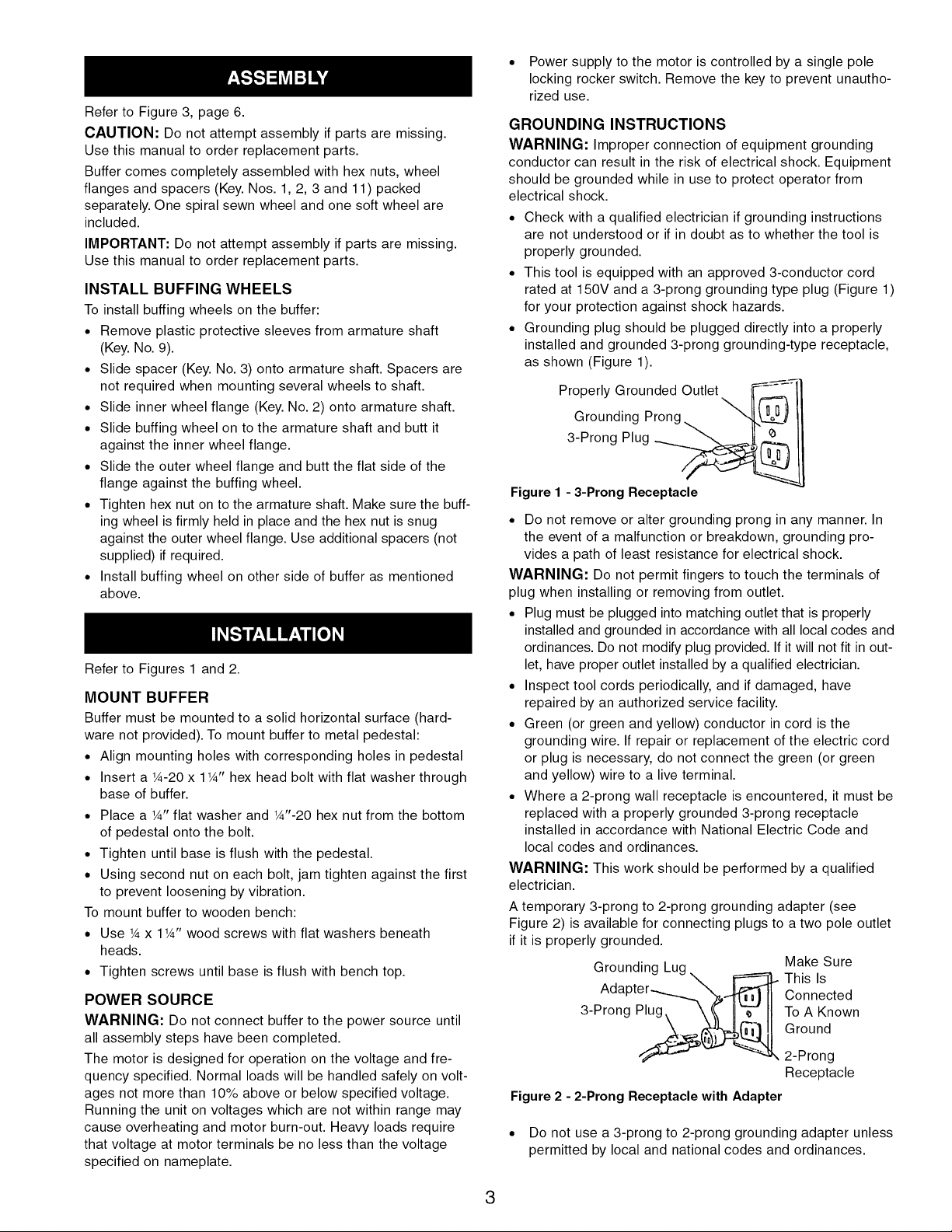
• This tool is equipped with an approved 3-conductor cord
rated at 150V and a 3-prong grounding type plug (Figure 1)
for your protection against shock hazards.
• Grounding plug should be plugged directly into a properly
installed and grounded 3-prong grounding-type receptacle,
as shown (Figure 1).
Grounded Outlet
Grounding Prong
3-Prong Plug
Properly __
Figure 1 - 3-Prong Receptacle
• Do not remove or alter grounding prong in any manner. In
the event of a malfunction or breakdown, grounding pro-
vides a path of least resistance for electrical shock.
WARNING: Do not permit fingers to touch the terminals of
plug when installing or removing from outlet.
• Plug must be plugged into matching outlet that is properly
installed and grounded in accordance with all local codes and
ordinances. Do not modify plug provided. If it will not fit in out-
let, have proper outlet installed by a qualified electrician.
• Inspect tool cords periodically, and if damaged, have
repaired by an authorized service facility.
• Green (or green and yellow) conductor in cord is the
grounding wire. If repair or replacement of the electric cord
or plug is necessary, do not connect the green (or green
and yellow) wire to a live terminal.
• Where a 2-prong wall receptacle is encountered, it must be
replaced with a properly grounded 3-prong receptacle
installed in accordance with National Electric Code and
local codes and ordinances.
WARNING: This work should be performed by a qualified
electrician.
A temporary 3-prong to 2-prong grounding adapter (see
Figure 2) is available for connecting plugs to a two pole outlet
if it is properly grounded.
Grounding Lug.
Adapter......_%_
3-Prong P_. __ 2-Prong
Figure 2 -
• Do not use a 3-prong to 2-prong grounding adapter unless
2-Prong Receptacle with Adapter
permitted by local and national codes and ordinances.
Make Sure
This Is
Connected
To A Known
Ground
Receptacle
3
(A 3-prong to 2-prong grounding adapter is not permitted in
Canada.) Where permitted, the rigid green tab or terminal on
the side of the adapter must be securely connected to a
permanent electrical ground such as a properly grounded
water pipe, a properly grounded outlet box or a properly
grounded wire system.
• Many cover plate screws, water pipes and outlet boxes are
not properly grounded. To ensure proper ground, grounding
means must be tested by a qualified electrician.
EXTENSION CORDS
• The use of any extension cord will cause some drop in volt-
age and loss of power.
• Wires of the extension cord must be of sufficient size to
carry the current and maintain adequate voltage.
• Use the table to determine the minimum wire size (A.W.G.)
extension cord.
• Use only 3-wire extension cords having 3-prong grounding
type plugs and 3-pole receptacles which accept the tool
plug.
• If the extension cord is worn, cut, or damaged in any way,
replace it immediately.
Extension Cord Length
Wire Size ................................... A.W.G.
Up to 25 ft....................................... 18
25 to 50 ft ....................................... 16
NOTE: Using extension cords over 50 ft. long is not
recommended.
ELECTRICAL CONNECTIONS
WARNING: All electrical connections must be performed by
a qualified electrician. Make sure tool is off and disconnected
from power source while motor is mounted, connected, recon-
nected or anytime wiring is inspected.
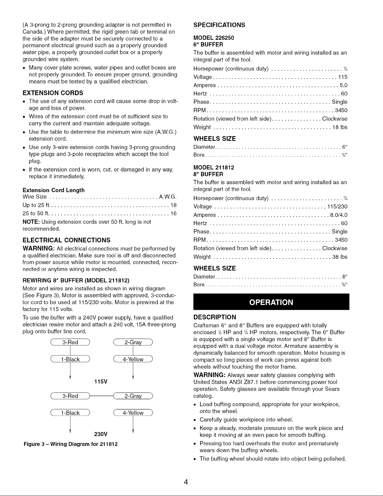
REWIRING 8" BUFFER (MODEL 211812)
Motor and wires are installed as shown in wiring diagram
(See Figure 3). Motor is assembled with approved, 3-conduc-
tor cord to be used at 115/230 volts. Motor is prewired at the
factory for 115 volts.
To use the buffer with a 240V power supply, have a qualified
electrician rewire motor and attach a 240 volt, 15A three-prong
plug onto buffer line cord.
3-Red "_ _ 2-Gray _
1-Black _ _ 4-Yellow _
115V
3-Red _-'__ 2-Gray
1-Black -'1 _ 4-Yellow
230V
Figure 3 -Wiring Diagram for 211812
SPECIFICATIONS
MODEL 226250
6" BUFFER
The buffer is assembled with motor and wiring installed as an
integral part of the tool.
Horsepower (continuous duty) ....................... 1/2
Voltage ........................................ 115
Amperes ....................................... 5.0
Hertz .......................................... 60
Phase ....................................... Single
RPM ......................................... 3450
Rotation (viewed from left side) ................ Clockwise
Weight ...................................... 18 Ibs
WHEELS SIZE
Diameter ........................................... 6"
Bore .............................................. 1/2"
MODEL 211812
8" BUFFER
The buffer is assembled with motor and wiring installed as an
integral part of the tool.
Horsepower (continuous duty) ....................... 3/4
Voltage .................................... 115/230
Amperes .................................... 8.0/4.0
Hertz .......................................... 60
Phase ....................................... Single
RPM ......................................... 3450
Rotation (viewed from left side) ................ Clockwise
Weight ...................................... 38 Ibs
WHEELS SIZE
Diameter ........................................... 8"
Bore .............................................. %"
DESCRIPTION
Craftsman 6" and 8" Buffers are equipped with totally
enclosed 1/2HP and 3/4HP motors, respectively. The 6" Buffer
is equipped with a single voltage motor and 8" Buffer is
equipped with a dual voltage motor. Armature assembly is
dynamically balanced for smooth operation. Motor housing is
compact so long pieces of work can press against both
wheels without touching the motor frame.
WARNING: Always wear safety glasses complying with
United States ANSI Z87.1 before commencing power tool
operation. Safety glasses are available through your Sears
catalog.
• Load buffing compound, appropriate for your workpiece,
onto the wheel.
• Carefully guide workpiece into wheel.
• Keep a steady, moderate pressure on the work piece and
keep it moving at an even pace for smooth buffing.
• Pressing too hard overheats the motor and prematurely
wears down the buffing wheels.
• The buffing wheel should rotate into object being polished.
4
 Loading...