

Craftsman 351226151 Owner’s Manual

RightFax 11/14/2002 9:40 PAGE 2/33 RightFax
Operator's Manual
CRRFTSMRN°
15"
PLANER
Model No,
351.226151
CAUTION: Read and follow
all Safety Rules and Operating
Instructions before First Use
of this Product.
Sears, Roebuck and Co., Hoffman Estates, IL 60179 U.S.A.
www._ar_ conVcraftsm an
17857.00 Draft (01/11/02)
RightFax ii/14/2002 9:40 PAGE 3/33 RightF&x
PREPARE WORK AREA FOR JOB
• Keepwork area clean. Clutteredwork areas invite
Warranty .................................. 2
Safety Rules.............................. 2-3
Unpacking................................. 3
Assembly ................................ 3-4
Installation ............................... 4-6
Operation ................................ 6-9
Maintenance ............................ 9-12
TroubLeshooting............................ 13
Parts Illustration and LIst .................. 14-19
EspeSol ............................... 20-31
accidents.
• Do notuse powertoolstn dangerousenvironments.
• Do notuse powertoolsin damp or wet locations. Do
notexpose powertools to rain.
• Work area shouldbe properlylighted.
• Proper electricalreceptacle shouldbe availablefor
tool Three prongplug shouldbe pluggeddirectly
into properly grounded, three-prongreceptacle.
• Extensioncords shouldhave a groundingprongand
thethree wires ofthe extensioncord shouldbeof
the correctgauge.
• Keep visitorsat a safedistancefrom work area.
• Keepchildrenoutof workplace.Makeworkshopchild-
FULL ONE YEAR WARRANTY
If this product fails due to a defectin materialor work-
manshipwithinone yearfrom the dateof purchase,
Searswillat itsoption repairor replaceItfreeof
charge.Contactyour nearest Sears ServiceCenter
(1-800-4-MY-HOME) to arrangefor productrepair,or
returnthisprodu_ to place of purchasefor replacement.
If thlsproductIs usedfor commercialor rental purpos-
es, thiswarrantywill applyfor 90 days fromthe date of
purchase.
Thiswarrantyappliesonly while this productIs usedIn
the United States.
This warrantygivesyou specificlegal rights andyoumay
also have otherrightswhichvaryfromstate to state.
Sears, Roebuck and Co., Dept. 817WA, Hoffman
Estates, IL 60179
proof. Use padlocks,master switchasor removeswitch
kaysto preventany unintentionaluseof powertools.
TOOL SHOULD BE MAINTAINED
• Always unplugtool priorto Inspection.
• Consultmanualfor specificmaintaining andadjust-
ingprocedures,
• Keeptool lubricatedand cleanfor safestoperation.
• Removeadjustingtools.Formhabitofcheckingto
see that adjustingtools are removedbefore switch-
ingmachineon.
• Keepan parts Inworkingorder.Check to determine
thatthe guard or other parts willoperate properly
and perform their intendedfunction,
• Checkfor damaged parts.Check for alignment of
movingparts, binding,breakage, mountingand any
otherconditionthat may affecta toots operation.
• A guardor other partthat isdamaged shouldbe
properlyrepairedor replaced.Do notperform
makeshiftrepairs.(Use partslistprovidedto order
WARNING: For your own safety,read all of the rules
replacementparts.)
and precautions beforeoperatingtool.
CAUTION; Always follow properoperatingprocedures
as definedIn this manual even Ifyou are familiar with
use ofthis or similartools,Remember that being care-
less foreven a fractionof a secondcan resultIn severe
personalInjury.
BE PREPARED FOR JOB
• wear properapparel. Do notwear loose clothing,
gloves,neckties,rings,braceletsor otherJewelry
which may get caughtin moving partsof machine.
• Wear protectivehaircoveringto containlong hair.
• Wear safetyshoeswith non-slip soles.
• Wear safetyglassescomplyingwith UnitedStates
ANSI 7.87.1.Everydayglasseshave onlyImpact
resistantlenses.They are NOT safetyglasses.
• Wear face mask or dustmask ifoperationIs dusty.
• Be alert and think clearly.Never operate powertools
when tired, Intoxicated or when taking medications
that causedrowsiness.
© Sears, Roebud_and Co.
KNOW HOW TO USE TOOL
• Use righttool for job. Do notforcetoolor attachment
to do a Jobforwhich it was not designed.
• Disconnecttoolwhen changingblades.
• Avoidacoidentaistart-ul_ Make surethatthe switch
Is Inthe OFF positionbeforepluggingin.
• Do notforcetool, Itwill work most efficientlyat the
ratefor which it was designed,
• Keep hands awayfrom movingparts and cutting
surfaces.
• Never leavetool runningunattended.Turnthe power
offend donotleave tool untilit comes to a complete
stop,
• Do not overreach.Keep proper footing and balance.
• Never standontool.Seriousinjurycouldoccuriftoolis
tippedor if blade Is unintentionallycontacted.
• Knowyour tool.Learnthe tool'soperation,applica-
tionand specificlimitations,
2
RightFax 11/14/2002 9:40 PAGE 4/33 RightF&x
• Use recommendedaccessories(referto page 15).
Use of improper accessories maycauserisk of
injuryto persons.
• Handle werkpieca correctly. Protect handsfrom pos-
sibleinjury,
• Turn machineoft if itjams. Bladejams when itdigs
toodeeply into workplese. (Motorforcekeeps it
stuckin the work.)
• Alwayskeep drive, cutterheadand blade guards In
place and in proper operatingcondition.
• Feed work intoblade or cutteragainstdlrectfonof
rotation.
CAUTION: Think safety!Safety Is a combination of
operatorcommon senseand alertnessat alltimes
when toolis being used,
WARNING: Do notattempt to operate tool untilit is
completely assembledacoordlngtothe Instructions.
Check for shippingdamage. If damage hasoccurred,a
claim must be fliedwith carrier. Check forcomplete-
ness.Immediately report missingparts todealer.
Additionalpartswhich needto befastenedto the planer
shouldbe locatedand accountedforbeforeassembling.
Planer is shipped assembled exceptfor thefollowing:
two table extensionswifh rollers,handwhael,handle,
chip chute,knifegauge rod,two knife gauges,hardware
bag,8/10 mmand 12/16 mmopen-endwrenches,and
3, 4, 5 and6 rnmhex wrenches.
Hardware bag includes:
• 8-1.25 x 20ram Hex Head Bolt (6)
• 6-1.0 x 12mm Socket Head Bolt(3)
• 6-1.0 x 12ram HexWasher Head Bolt (3)
• 6-1.0mm H_ Nut (3)
• 10-1.25mm Hex Nut (1)
• 6turnFlatWasher (6)
• 8mm FlatWasher (6)
• 10mm FlatWasher (1)
• 6rnrnLockWasher (3)
• 8-1.25 x 12mmSet Screw (6)
• 3 CMI-11 E-ring(4)
• 4x 4x 10mm Kay
• DirectionIndicator
IMPORTANT: Table is coated wifh a protectant.To
ensureproperfit and operation,removecoating.
CoatingIs easily removedwith mildsolvents,suchas
mineral spirits,and a soft cloth.Avoidgettingsolution
on paint or any of the rubber or plasticparts.Solvents
may deterioratethese finishes. Use soapand water on
paint, plasticor rubbercomponents, Aftercleaning,
cover allexposed surfaceswith a lightcoating ofoil
Paste wax Is recommended for tabletop.
WARNING: Never usahighlyvolatilesolvents.Non-
flammablesolventsare recommendedto avoidpossible
fire hazard.
WARNING: Do not attempt assemblyif partsare
missing. Usethis manual to orderreplacement parts.
PLANER INSTALLATION
Referto Figure20.
Beforeplaner isassembled,a suitablelocationshould
be chosen.The planerweighs approximately550 Ibs
when completely assembled.Planer shouldbe assem-
bledon location.
Planer needsto be set on a flat, level surface.This
improvesstability, accuracyand preventswarpage
and failureofcast components and welds.Adjust
machine levelersor use shimsas required.
Make sure there is arnpleroom on beth Infeedand
outfeedsidesof planerfor movingthe workplace
throughthe entire cut,There must be enoughroom
that neitherthe operatorsnorthe bystanderswill
haveto stand in linewith thewoodwhile usingthe
tool.
Good lightingand correct powersupply(230 volts)
are alsorequiredfor e properwork area.
Place planer in its designatedspot.Door panelfor
accessto motor is on back side.The planeris sup-
pliedwithfour movinghandlesthat slide intothe
base onthe infeedand outfeed sides.The planer
can be liftedbythese handlesand movedto the
required location.
MOUNT TABLE EXTENSIONS
Refer to Figure1, page 4,
• Required hardware:
8-1.25 x 20mmHex Head Bblt(6)
8rnm FlatWasher (6)
8-1.25 x 12ramSet Screw(6)
• Mounttable extensionto planertable onthe lnfeed
sideusingthree 8-1.25 x 20mrnhe_ head boltsand
8mm flatwashers, Do nottighten bolts.
• Thread three 8-1.25 x 12mm set screwsinto exten-
sions.
•Placa long straight edge acrosstable and table
extensions.
• Adjustset screwssothat the table extensionis at
the same heightasthe table.
• Tightenbaitsto secureextension.
• Repeat abovesteps forthe outfeede0(tension.
3
RightFm× ii/1412002 9:40 PAGE 5/33 RightF&×
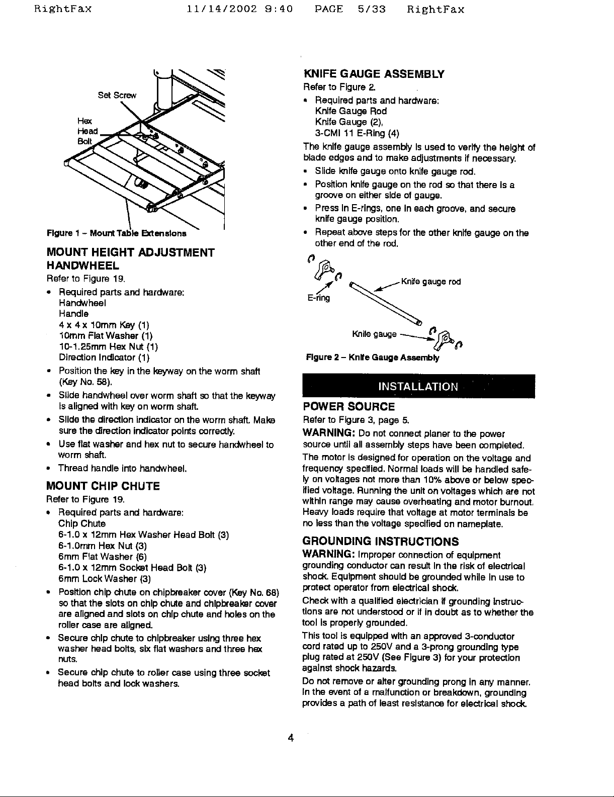
KNIFE GAUGE ASSEMBLY
Referto Figure2.
• Required parts and hardware:
KnifeGauge Rod
KnifeGauge (2),
3-CMI 11 E-Ring(4)
The knifegauge assemblyIs usedto verifythe heightof
bladeedges and to makeadjustmentsif necessary.
• Slide knifegauge onto knifegaugerod.
• Positionknifegauge on the rod so thatthere isa
grooveon eithersideof gauge.
• PressIn E-rings,one ineach groove,end secure
knifegaugeposition.
Figure1- MountTi 4eExtensions
MOUNT HEIGHT ADJUSTMENT
HANDWHEEL
Refer to Figure 19.
• Requiredparts and hardware:
Handwhael
Handle
4 x 4x lOmm Key (1)
lOmm Flat Washer (1)
10-1.25mm Hex Nut(1)
Direction Indicator (1)
• Positionthe k_=yin the keywayonthe worm shaft
• Repeat above steps forthe other knifegauge on the
otherend ofthe rod.
¢J_0 " rod
Figure2 - KnifeGaugeAssembly
(KeyNo.58).
• Slide handwheel over worm shaftsothat the keyway
isaligned with key on worm shaft.
• Slide the direction Indicator onthe worm shaft.Make
surethe directionindicatorpointscorrectly.
• Use flat washer and hexnutto securehandwheelto
worm shaft.
• Thread handle intohandwhael.
MOUNT CHIP CHUTE
Refer to Figure 19.
• Required parts and hardware:
Chip Chute
6-1.0 x 12ram Hex Washer Head Bolt(3)
6-1.0mm Hex Nut (3)
6ram FlatWasher (6)
6-1.0 x 12ramSocle_tHead Bolt(3)
6ram LockWasher (3)
• Positionchipchuteon chipbreakercover(KeyNo.68)
sothatthe slotson chip chute and chlpbreekercover
are alignedand slotson chipchuteand holesonthe
rollercase are aligned.
• Secure chipchute to chlpbreakerusingthree hex
washer head bolts,sixflatwashersand three he:<
nuts.
• Secure chip chute to roller case using three socket
head bolts and lock washers.
POWER SOURCE
Refer to Figure3, page 5.
WARNING: Do not connectplaner to the power
sourceuntilall assemblysteps havebeen completed.
The motoris designedfor operationonthe voltageand
frequency specified.Normal loadswillbe handled safe-
lyon voltagesnot morethan 10% aboveor below spec-
ifiedvoltage.Runningthe uniton voltageswhich are not
wifhlnrange may cause overheatingandmotorburnout,
Heavy loadsrequire that voltageat motorterminals be
no less thanthe voltage specifiedon nameplate.
GROUNDING INSTRUCTIONS
WARNING: Improperconnection of equipment
groundingconductor can resultIn the riskof electrical
shock.Equipmentshouldbe groundedwhile In use to
protectoperatorfrom electricalshock,
Check witha qualifiedelectricianif groundinginstruc-
tionsare not understoodor if in doul_ as to whetherthe
toolIs properlygrounded.
This toolts equippedwith an approved3-conductor
cord rated up to 250V and a 3-pronggroundingtype
plug ratedat 250V (See Figure3) for yourprotection
againstshockhazards.
Do notremoveor altergroundingprongIn any manner.
In the event of a malfunction or breakdown,grounding
provides a pathof least reslstancafor electricalshock.
4
Righ%F&x 11/14/2002 9:40 PAGE 6/33 RightFax
WARNING: Do not permit fingers totouch the termi-
nals of plug when installing or remevlncfromoutlet.
Grounding Pin
Figure 3 - Grounding Methods
Plugmust be pluggedintoa 230V matchingoutlet(See
Figure3) that is properlyinstaUedandgroundedin aocer-
dancewithall localcodesand ordinances,Do notmodify
plugprovided.If it will notfit inoutlet,have properoutlet
Installed_ a qualifiedelectrician.
Inspecttoolcordsperiodically,and ifdamaged, have
repeited by an authorized servlsefacility,
Green (orgreenand yellow)conductorin cord isthe
groundingwire.If repair or replacementof the electric
cordor plug isnecessaw, donot connect the green (or
greenand yellow) wire to a liveterminal.
Where a 2-pmng wall receptacleIs encountered,it
mustbe replacedwith a properlygrounded3-prong
receptacleinstalledin accordancewith NationalElectric
Code and local codesand ordinances.
WARNING: This work should be performed by a
qualified electrician.
EXTENSION CORDS
• The use of any extensioncordwillcause some drop
Lnvoltageand lossof power.
• Wires of the extensioncord must be of sufficientsize
to carry the currentand maintainadequate voltage.
• Usethe table to determine the minimumwire size
(A.W.G.) extensioncord.
* Useonly 3-wireextension cordshaving3-prong
groundingtype plugsand 3-pole receptacleswhich
acceptthe toolplug.
If the extensioncord is worn, cut, or damaged in any
way,replace it Immediately.
EXTENSION CORD LENGTH
Wire Size A.W.G.
Upto 50ft................................ 14
NOTE: Usingextensioncords ever 50 ft. long Isnot
recommended.
ELECTRICAL CONNECTIONS
Referto Figure 4.
WARNING: All eleotricalconnections mustbe per-
formed bya qcallfled electrician.Make sureunitisoff
and disconnectedfrom powersourcewhile motoris
mounted,connected, reconnectedor anytimewiring is
Inspected.
Planerhasan approved230 voltthree-conduotorline
curdwitha three-pronggroundingtypeplug,and a 230
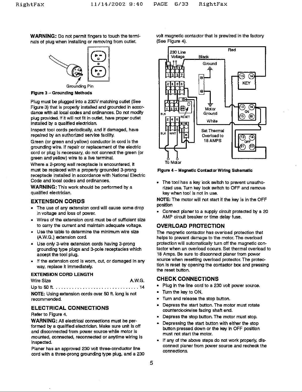
volt magnetic contactor that is prewired in the factory
(See Figure 4),
Black Red
Ground
Ground
Motor ,M
White t
SetThermal
18AMPS
Ovedoadto
To Motor
Rgure 4 - Magnetic Contactor Wiring Schematic
• The toolhas a key lock switchto prevent unautho-
rized use.Turnkey lockswitchto OFF andremove
keywhentool isnot in use.
NOTE: The motorwellnotstart ifthe key is inthe OFF
position
• Connect planerto a supplycircuitprotectedbya 20
AMP circuitbreakeror time delayfuse.
OVERLOAD PROTECTION
The magneticcentactor has overloadprotectionthat
helpsto preventdamage to the motor.The overload
protectionwillautomaticallyturn offthe magneticcen-
tactorwhen an overloadoccurs.Set thermaloverloadto
18 Amps. Be suretodisconnectplanerfrom power
sourcewhen resettingoverloadprotector.The protec-
tionis resetby openingthe contactor boxand pressing
the resetbutton.
CHECK CONNECTIONS
• Plugin theline cord to a 230 volt power source.
• Turnthe keyto ON,
• Turn and release the stopbutton,
• Depress the start button.The motormust mtate
counterclockwise facingshaftend.
• Depress the stopbutton.The motormust stop.
• Depressingthe start buttonwith eitherthe stop
buttonpresseddown or the key InOFF position
mustnotstart the motor.
• If any of the above steps do notwork properly,dis-
connectplaner from power source and recheckthe
connections.
5
RightFax 11/14/2002 9:40 PAGE 7/33 KiEhtFax
Do notforce cut.Slowingor stalling willoverheat
motor.Allow automaticfeed to functionproperly.
DESCRIPTION
Referto Figures5-20.
Craftsman15" Planer isa heavyduty cast ironunitthat
can plane lumbar upto 15"wide and 6" thick`Planer
hasa 3" diameter,3-blade cutterheadwith jack screws
for easy blade adjustmentand replacement.Cutterhead
and feed rollerstravel on precisiongroundsteel
columns.Lumbercan be fed at 16 or20 feet per minute
and can becut up to ',V"deep per pass.
Planarcomes with totallyenclosedwelded platesteel
cabinet withbuilt-inmobilebase, 4" portfor dustcollec-
tionand safetyelectricalcontrolwith magneticcontector.
includes3 HP RPM motor.
SPECIFICATIONS
Tablesize .......................... 20 x 15'/,"
Tablewith rollerextensions .................. 51"
Bladewidth .............................. 15"
Maximumcut......................... ,/,"Deep
Floorspace ..................... 4-3'hx 51 x 31"
V-pelts................................. M-60
Dust collectionport .................. 4" Diameter
Motor ......................... 3 HP,3500 RPM
Planing refers to the sizingof lumbar to a desired thick-
ness while creatinga level surfaceparallel to the oppc-
site sizeof the board.Depth of cut is the term used to
Indicate how deep the blades will cut Into the work-
piece.
OPERATION SAFETY RULES
WARNING: Operation of any power tool can resultIn
foreign objects beingthrown intoeyes which can result
in severe eye damage. Always wear safety goggles
complying with UnitedStates ANSI 7_87.1(shownon
package) before commencingpowertool operation.
CAUTION: Always observethe following safety
precautions:
• Knowgeneral powertool safety.Make sureall
precautionsare understood(See pages 2, 3 and 6).
Use qualitylumber.Blades lastlongerand cutsare
smootherwithgood qualitywood.
Do not performplaningoperationson materialshort-
erthan 17•, narrowerthans/,,, or less than '/="thick,
Never make planing operationon materialwider than
15" or cutdeeperthan ',V'
Always keep cutterheadand bladeguards in proper
workingcondition.
Maintainthe properrelationshipsof Infeed and out-
feed table surfacesand cutterheadblade path.
Do not packthe worktowardthe infeedtable.
Supportthe workpieceadequatelyat all times during
operation;maintain controlof theworkpieca.
Take precautionsagainst kickback.Do not permit
anyoneto stand or crossin line of cutterheads rota-
tion. Kickbackor throwndebriswilltravel Inthis
direction.
Turn switchoff and disconnectpowerwheneverplan-
er isnot in use.
Replace or sharpen bladesas they become dam-
aged or dull.
Keep planar maintained.Followmaintenance
instructions (See pages 9-12).
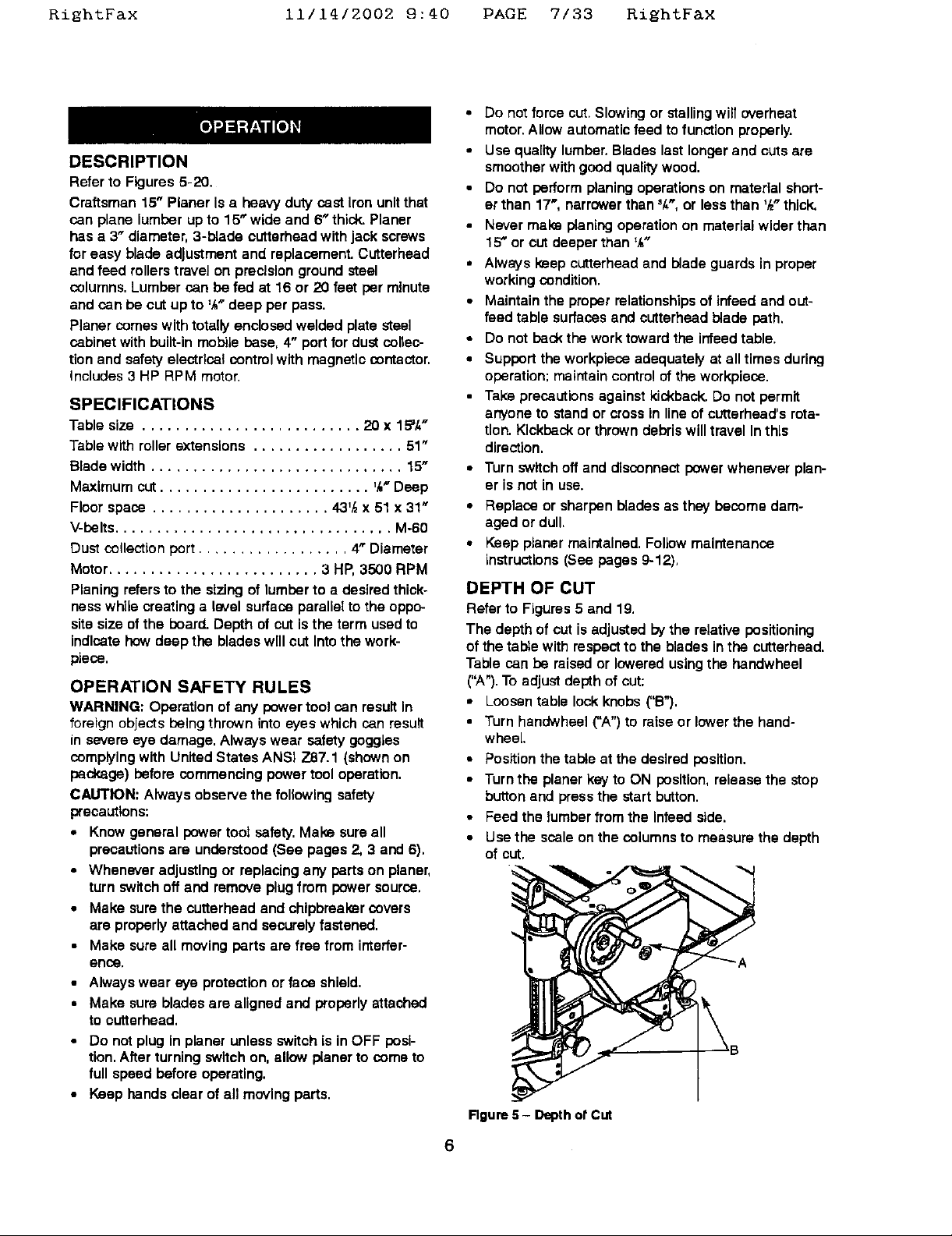
DEPTH OF CUT
Refer to Figures 5 and 19.
The depth of cut is adjusted by the relative positioning
of the table with respect to the blades in the cutterhead.
Table can be raised or lowered using the handwheel
("A").To adjust depth of cut:
• Loosen table lock knobs ("B").
• Turn handwheel CA") to raise or lowerthe hand-
wheel
• Position the table at the desired position.
• Turn the planer key to ON position, release the stop
button and press the start button.
• Feed the lumber from the Infeed side.
• Use the scaleon the columnsto measure the depth
of cut.
• Whenever adjustingor replacingarTypartson planer,
turnswitchoff and removeplugfrom powersource.
• Make surethe cutterheadand chipbreakercovers
are properlyattached and securelyfastened.
• Make sureall movingparts are free from interfer-
enoe.
• Always wear eye protection or face shield.
• Make sure blades are aligned and properly attached
to cutterhead.
• Do notplug in planer unless switchis inOFF posi-
tion.After turningswitch on, allowplanerto come to
full speedbeforeoperating.
• Keep hands clear of all moving parts.
Rgure 5- Depthof CUt
6
RightFax 11/14/2002 9:40 PAGE 8/33 RishtFax
• To increase depthof cut raisethe table:to decrease
depthof cutlowerthe table.
• Tighten the table lock knobs.
• When planingseveral pieces of wood, planeall the
lumber with the same set-upto have uniformthick-
ness removed.
A depth of cut limiter (Figure 19, Key No. 38) is
provided to limit depth of cut to maximum of 'At
Do not make planing outs deeper than _,V'.
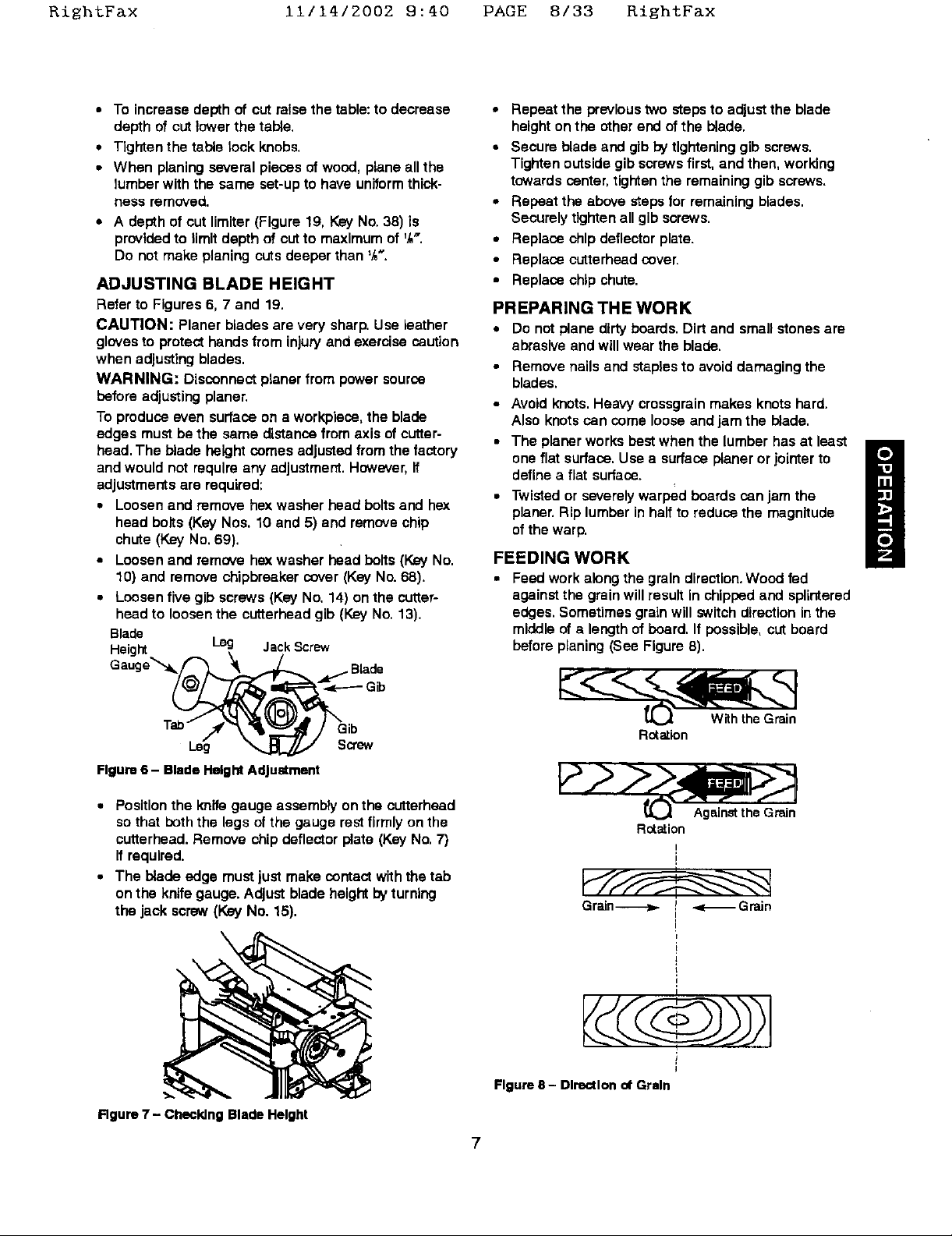
ADJUSTING BLADE HEIGHT
Refer to Figures 6, 7 and 19,
CAUTION: Planer blades are very sharp.Use laather
glovesto protecthandsfrom injury and exercisecaution
when adjustingblades.
WARNING: Disconnectplanerfrom powersource
beforeadjustingplaner.
To produce even surfaceon a workplace,the blade
edges mustbe the same distancefrom axis of cutter-
head.The blade height comes adjustedfrom the factory
andwould not raqulra any adjustment.However,if
adjustments are required;
• Loosenand remove hex washer head boltsand hex
head bolts (Key Nos. 10 and 5) and removechip
chute (KeyNo.69).
• Loosenand remove hex washer head bolts(Key No.
10) and removechipbraakercover (Key No. 68).
• Loosenfive gib screws(Key No. 14) on the cutter-
head to loosenthe cutterheadgib (Key No.13).
Blade
Height leg JackScrew
Gauge'_
• Repeat the previoustwo steps to adjustthe blade
heightonthe other endof the blade.
• Secure blade and glb bytighteninggib screws.
Tightenoutsidegib screwsfirst, and then, working
towardscenter, tightenthe remaininggib screws.
• Repeat the abovesteps for remainingblades.
Securelytightenall gib screws.
• Replace chipdeflectorplate.
• Replace cutterheadcover.
• Replace chip chute.
PREPARING THE WORK
• Do not plane dirty boards. Dirt and small stones are
abrasive and will wear the blade.
Remove nails and staples to avoiddamagingthe
blades.
• Avoid knots. Heavy crossgrain makes knots hard.
Also knots san come loose and jam the blade.
• The planer works best when the lumber has at least
one flat surface. Use a surface planer or jointer to
define a flat surface.
• Twisted or severely warped boards can jam the
planer. Rip lumber in half to reduce the magnitude
of the warp.
FEEDING WORK
• Feed work along the grain direction. Wood fed
against the grain will result in chipped and splintered
edges. Sometimes grain will switch direction inthe
middle of a length of board. If possible, cut board
before planing (See Figure 8).
m
6_
Figure 6- Blade Height Adjustment
• Position the knife gauge assembly on the cutterhead
so that both the legs of the gauge rest firmly on the
cutterhead. Remove chip deflector plate (Key No, 7)
if required.
• The blade edge must just make contact with the tab
on the knife gauge. Adjust blade height by turning
the jack screw (Key No. 15),
\
Rgure 7 - Checking Blade Height
Rotation
Rotation
Grain----->. I -._-_Grain
Figure 8 - Direction ot Grain
Against the Grain
!
I
!
!
i
RightF&x iii14/2002 9:40 PAGE 9/33 RightF&x
CAUTION: Do not plane a beard which Is less than
17" long. The force of the cut could split the board and
cause a kickback,
• Turn the planer on.
• Stand on the side of the planer to which the height
adjustment handwheal was attached.
• Lift the workto infeed support roller by grasping
edges at approxlmeteiy the middle of the length,
• Boards longer than 24" should have additional sup-
port from free standing material stands (See
Recommended Accessories, page 15).
• Rest the board end on infeed support roller and
direct the board Into the planer.
• Push slightly on board and allow automatic feed to
takB the board. Release beard and allow automatic
feed to function properly. Do not push or pull on
workpiace.
CAUTION: Do not stand directly in line with front or
rear of planer. When an object is projected from planer
itwill travel in this direction.
• Move to the side and receive the planed lumber by
grasping it in the came manner in which itwas fed,
• Do not grasp any portion of the board which has not
gone past the outfeed support roller,
• Repeat this operation on all beards which need to be
the same thickness or adjust the height.
• The planer has return roflers on the top so an
assistant can pass work beck to the operator,
NOTE: An assistant must follow the same precautions
as the operator_
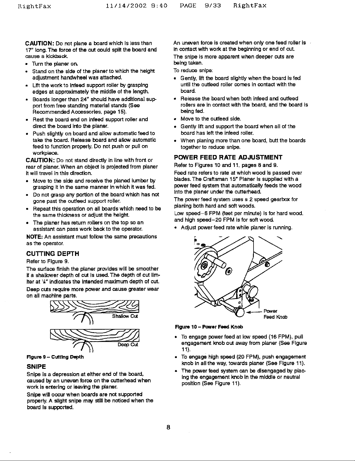
C U'I-I'ING DEPTH
Refer to Figure9.
The surfacefinishthe planer provideswill be smoother
it a shallowerdepth of cut Is used.The depth of cutUm-
iter at ',_"indicatesthe intended maximum depthof cut.
Deep cutsrequire morepowerand cause greater wear
on all machine parts.
An unevenforce is createdwhen onlyone feed rolleris
in contactwith workat the beginningor end of cut.
The snipeis moreapparentwhen deeper cutsare
being taken.
To reduce snipe:
• Gently, liftthe board slightlywhen the board Is fed
untilthe outfeadrollercomesin contactwith the
board.
• Release the boardwhen beth infeed and ouffaad
rollersare incontactwiththe beard, andthe beard is
beingfad.
• Moveto the outfaed side.
• Gentlyliftand supportthe boardwhen all of the
beard has leftthe infeed roller.
• When planing morethan one beard, buttthe boards
togetherto reduce snipe.
POWER FEED RATE ADJUSTMENT
Refer to Figures10 and 1% pages 8 and 9.
Feed rate refersto rate at whichwood is passed over
blades.The Craftsman15" Planer is suppliedwitha
powerfeed systemthat automaticallyfeeds the wood
Intothe planerunderthe cutterhead.
The powerfeed system usesa 2 speed gearboxfor
planingbeth herd and softwoods.
Lowsbeed-6 FPM (feet per minute)Isfor hard wood,
and highspeed-20 FPM isfor soft wood.
• Adjustpower feed ratewhile planer is running.
Rgure9- CuttingDepth
SNIPE
Snipe Is a depressionat either end ofthe beard,
caused by an unevenforce on the cutterbeedwhen
work is entering or leevingthe planer,
Snipewilloccurwhen beards are not supported
properly,A slightsnipe may stnibe noticedwhenthe
board Is supported,
-4e----- Power
Feed Knob
Figure 10 - Power Feed Knob
• To engage power fead at low speed (16 FPM), pull
engagementknobout awayfrom planer (See Figure
11).
• To engagehigh speed (20 FPM), pushengagement
knobin allthe way,towardsplaner (See Figure11).
• The powerfeed system can be disengagedby plac-
Ingthe engagementknob In the middleor neutral
position(See Figure 11).
8
_ightFax 11/14/2002 9:40 PAGE 10/33 RightFax
m
i
O
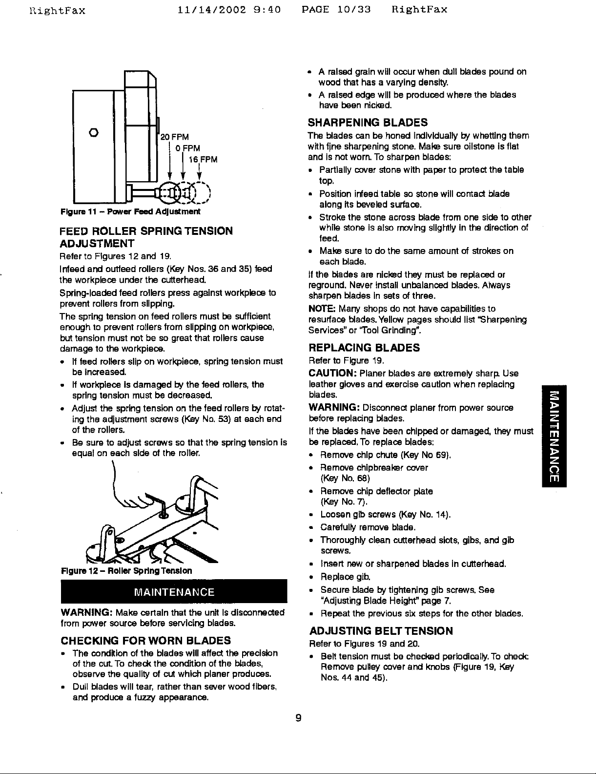
Figure 11 - Power Feed AdJuldment
FEED ROLLER SPRING TENSION
ADJUSTMENT
Refer to Figures 12 and 19.
Infeed and outfeed rollers (Key Nos. 36 and 35) feed
the workplace under the cutterhaad.
Swing-loaded feed rollers press against workplece to
prevent rollers from slipping.
The spring tension on feed rollers must be sufficient
enough to prevent rotlers from slipping on wcrkpiece,
but tension must not be so great that rollers cause
damage to the workplace.
• If feed milers slip on workpfece, spring tension must
be increased.
20 FPM
0 FPM
• Ifworkpleca is damaged bythe feed rollers,the
springtensionmust be decreased.
• Adjustthe springtension on thefeed rollersbyrotat-
ingthe adjustmentscrews(KeyNo.53) at each end
of the rollers.
• Be sure toadjustscrews sothat the springtensionis
equal on each side of the roller.
Figure 12 - Roller Spdng Tenelon
WARNING: Make certain that the unit Is disconnected
from power source before servicingblades.
CHECKING FOR WORN BLADES
• The condition of the blades will affect the precision
of the cut. To check the condition of the blades,
observe the quality of cut which planer produces.
• Dull blades will tear, rather than sever wood fibers,
and produce a fuzzy appearance.
• A raised grain will ocour when dull blades pound on
wood that has a varying density.
• A raised edge will be produced where the blades
have been nicked.
SHARPENING BLADES
The blades can be honed individually by whetting them
with fine sharpening stone. Make sure oilstone is flat
and is not worn. To sharpen blades:
• Partially cover stone with paper to protect the table
top.
• Position infead table so stone will contact blade
along its beveled surface.
• Stroke the stone across blade from one side to other
while stone is also moving slightly in the direction of
feed.
• Make sure to do the same amount of strokes on
each blade.
tf the blades are nici_d they must be replaced or
reground. Never install unbalanced blades. Always
sharpen blades in sets of three.
NOTE: Many shops do not have capabilities to
resurface blades. Yellow pages should list "Sharpening
Services" or "1"oolGrinding".
REPLACING BLADES
Refer to Figure19.
CAUTION: Planer blades are extremelysharp,Usa
leatherglovesand _0cercisecautionwhen replacing
blades.
WARNING: Disconnectplanerfrom powersource
beforereplacingblades.
Ifthe bladeshave been chippedor damaged, they must
be replaced.To replacablades:
• Remove chip chute(Key No 69),
• Remove chipbreakercover
(Key No.68)
• Remove chip deflectorplata
(Key No.7).
• Loosen gib screws(Key No. 14).
* Carefully remove blade.
• Thoroughlyclean cutterhaadslots,gibs,and gib
screws.
• insert new or sharpened bladesin cuttarhead,
• Replacegib,
• Secure bladeby tighteninggib screws.See
"Adjusting Blade Height"page 7,
• Repeat the previoussixstepsforthe otherblades,
ADJUSTING BELT TENSION
Refer to Figures 19 and 20.
• Belt tension must be checked periodically. To check:
Remove pulley cover and knobs (Figure 19, Key
Nos. 44 and 45).
9
RightFax 11/14/2002 9:40 PAGE 11/33 R±ghtF&x
• Adjust bolt tension by pivoting motor mounting plate
(Figure 20, Key No. 13). Pivot plate by loosening he_
nuts on tension bolt (Figure 20, Key Nos. 11 and 14)
as required.
• Belt ts properly tensioned when slight pressure
between thumb and inde_€finger causes '/z" deflec-
tion of bolt.
• Be sure to replace pulley cover and knobs,
LUBRICATION
The planergearbox has beenfilledwith lubrioatingoil
at the factory. The gearbox oil shouldbe changedeach
30 hours of operation.To changeo11:
• Drain old gearbox oil by removingplugat bottomof
gearbox.
• Replace drain plug.
• Remove fill plugat top of gearbox,
• Fillgearbox with 50 or 60 weightgear o11.
• Fill untiloll levelIs up to plughole.
• Replace fill plug.
Frequentlylubricateslidingsurfacesof columnswith
graphiteor industrialgrease.
ANTI-KICKBACK PAWLS
Refer to Figure 19,
The anti-kickback pawls (Key No. 21 ) prevent the work-
piece from kicking back against the direction of feed.
The pawls must rotate freely to ensure safe operation
of the planer.
• Inspect the anti-kickback pawls daily for proper oper-
ation checking that the pawls rotate freely.
• Clean the pawls of all gum and chips as required to
ensure safe operation.
TABLE ROLLER ADJUSTMENT
Refer to Figure 20.
The tablerollers(KeyNo. 59) are free-spinningrollers
that helpreducefriction, makingthe planingoperation
smoother.
The properheightof the table rollersisdependentupon
the hardnessand surfacefinishof the work,piece:
• The rollerheight shouldbe adjusted sothatthe
workplacefeeds smoothlythroughthe planerbutis
not damaged bythe table rollersor bythe feed
rollers.
• Roughcutwood requiresthe rollersto be adjusteda
littlehigher,while smoothfinishwood requiresthe
rollersto be a littlelower.
• Forall workplacematerialsand finishesthe table
rollersshould be positionedslightlyabove the table.
• Table roller heightIsadjusted by looseningset
screws(KeyNo.73) and rotatingeccentricadjusters
(Key No.57).
• Use a straight edge acrossthe table and table
rollersto checkmiler adjustment.
• Be sure thatboth ends of the table rollersare at the
same heightso that the rollersare parallel withthe
table and secureeccentricadjusterswith set screws
(Key No.73),
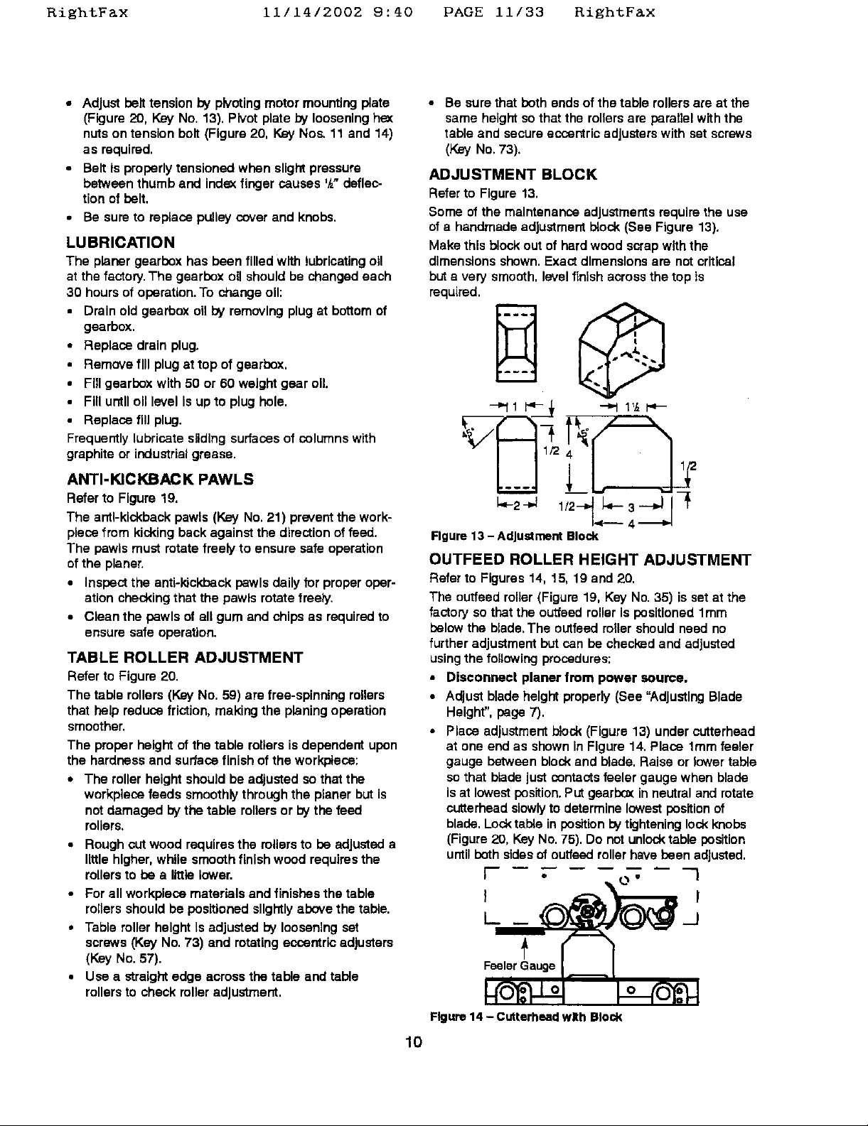
ADJUSTMENT BLOCK
Refer to Figure 13.
Some ofthe maintenance adjustmentsrequirethe use
ofa handmadeadjustmentblock (See Figure 13).
Makethis block out of hard wood scrapwiththe
dimensionsshown.Exactdimensionsare notcritical
but a very smooth,levelfinishacrossthe top Is
required.
_"11 i'_- ,_ _ 1'/_1_-
Figure 13 - Adjustment Block
OUTFEED ROLLER HEIGHT ADJUSTMENT
Referto Figures 14, 15, 19 and 20.
The outfeed roller(Figure19, Key No.35) isset at the
factory so that the outfeedrollerIs positioned 1ram
belowthe blade.The outfeedrollershouldneed no
further adjustmentbut can be checkz_dand adjusted
usingthe following procedures:
• Disconnect planer from power source.
• Adjust bladeheight properly(See "Adjusting Blade
Height".page 7).
• Place adjustmentbiock(Figure 13) under cutterhead
at one end as shownIn Figure14. Place 1ramfeeler
gauge betweenblockand blade.Raise or lower table
sothat bladejustcontactsfeeler gaugewhen blade
isat lowestposition.Putgearboxin neutraland rotate
cutterheadslowlyto determine lowestposition of
blade.Locktable in position _ tighteninglockknobs
(Figure20, KeyNo. 75). Do not unlocktable position
untilbothsidesof ouffeedrollerhave been adjusted.
l" , O" I
I-.__ _J
'
,°rOooo°"]
Figure 14 - Cutterheed w£h Block
10
 Loading...