

Craftsman 351226061 Owner’s Manual

CRRFTSMRNo
Operator's Manual I
6 x 48" Oscillating Belt
12" Disc
SANDER
Model No.
351.226061
CAUTION: Read and follow
all Safety Rules and Operating
Instructions before First Use
of this Product.
Sears, Roebuck and Co., Hoffman Estates, IL 60179 U.S.A.
17985.00 Draft (01/18/02)

Warranty ....................................... 2
Safety Rules .................................... 2
Unpacking ..................................... 3
Assembly ..................................... 3-4
Installation .................................... 4-5
Operation .................................... 5-8
Maintenance .................................... 8
Troubleshooting ................................. 9
Parts illustrationand List ....................... 10-13
Espahol .................................... 14-23
FULL ONE YEAR WARRANTY ON CRAFTSMAN
BELT & DISC SANDER
if within one full year from the date of purchase, this
Craftsman sander fails due to a defect in material or work-
manship, Sears will repair it free ofcharge. Warranty service
is available by contacting Sears in-home major brand repair
service.This warranty gives you specific legal rights and you
may also have other rights which vary from state to state.
If this sander is used for commercial purposes, this warranty
applies for only 90 days from the date of purchase.
Sears, Roebuck and Co., Dept. 817WA, Hoffman Estates, IL
60179
WARNING: For your own safety, read all of the instructions
and precautions before operating tool.
CAUTION: Always follow proper operating procedures as
defined in this manual even if you are familiar with use of this
or similar tools. Remember that being careless for even a
fraction of a second can result in severe personal injury.
BE PREPARED FOR JOB
• Wear proper apparel. Do not wear loose clothing, gloves,
neckties, rings, bracelets or other jewelry which may get
caught in moving parts of machine.
• Wear protective hair covering to contain long hair.
• Wear safety shoes with non-slip soles,
• Wear safety glasses complying with United States ANSI
Z87.1. Everyday glasses have only impact resistant lenses.
They are NOT safety glasses.
• Wear face mask or dust mask if operation is dusty.
• Be alert and think clearly. Never operate power tools when
tired, intoxicated or when taking medications that cause
drowsiness.
PREPARE WORK AREA FOR JOB
• Keep work area clean. Cluttered work areas invite accidents.
• Do not use power tools in dangerous environments. Do not
use power tools in damp or wet locations. Do not expose
power toolsto rain.
• Work area should be properly lighted.
• Proper electrical receptacle should be availablefor tool.
Three prong plug should be plugged directly into properly
grounded, three-prong receptacle.
• Extension cords should have a grounding prong and the three
wires of the extension cord should be of the correct gauge.
• Keep visitors at a safe distance from work area.
• Keep children out of workplace. Make workshop childproof.
Use padlocks, master switches or remove switch keys to
prevent any unintentional use of power tools.
TOOL SHOULD BE MAINTAINED
• Always unplug tool prior to inspection.
• Consult manual for specific maintaining and adjusting
procedures.
• Keep tool lubricated and clean for safest operation.
• Remove adjusting tools. Form habit of checking to see that
adjusting tools are removed before switching machine on.
• Keep all parts in working order, Check to determine that the
guard or other parts will operate properly and perform their
intended function.
• Check for damaged parts. Check for alignment of moving
parts, binding, breakage, mounting and any other condition
that may affect a tool's operation.
• A guard or other part that is damaged should be properly
repaired or replaced. Do not perform makeshift repairs.
(Use parts list provided to order replacement parts.)
KNOW HOW TO USE TOOL
• Use right tool for job. Do notforce tool or attachment to do
a job for which it was not designed.
• Disconnect tool when changing belt or abrasive disc.
• Avoid accidental start-up. Make sure that the tool is in the
"OFF" position before plugging in.
• Do not force tool. It will work most efficiently at the rate for
which it was designed.
• Keep hands away from moving parts and sanding surfaces.
• Never leave tool running unattended. Turn the power off
and do not leave tool until it comes to a complete stop.
• Do not overreach. Keep proper footing and balance,
• Never stand on tool. Serious injury could occur if tool is
tipped or if belt or disc are unintentionally contacted.
• Know your tool. Learn the tool's operation, application and
specific limitations.
• Use recommended accessories (refer to page 11). Use of
improper accessories may cause risk of injury to persons.
• Handle the workpiece correctly. Protect hands from possi-
ble injury.
• Turn machine off if it jams. Belt jams when it digs too
deeply into workpiece. (Motor force keeps it stuck in the
work.)
• Support workpiece with miter gauge, belt platen or work
table.
• Maintain Y,," maximum clearance between table and sand-
ing belt or disc.
CAUTION: Think safety! Safety is a combination of operator
common sense and alertness at all times when tool is being
used.
WARNING: Do not attempt to operate tool until it is com-
pletely assembled according to the instructions.
2
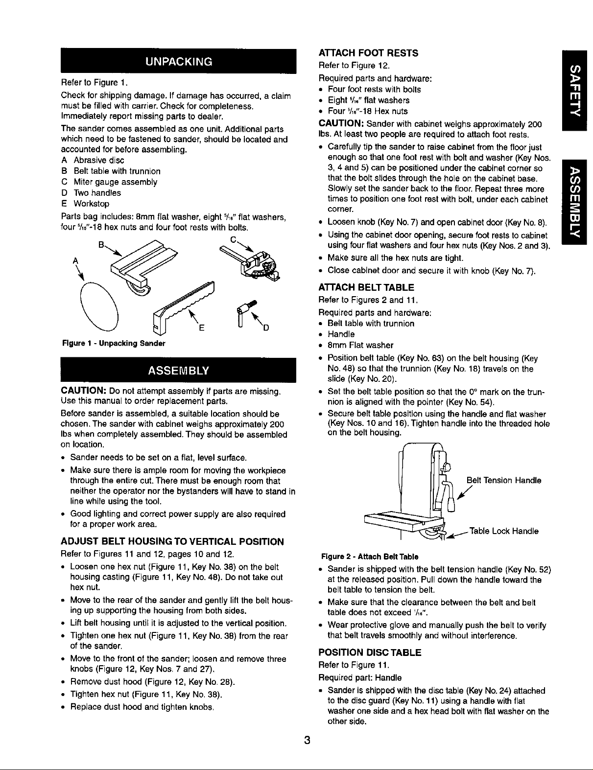
Refer to Figure 1.
Check for shipping damage. If damage has occurred, a claim
must be filled with carrier. Check for completeness.
Immediately report missing parts to dealer.
The sander comes assembled as one unit. Additional parts
which need to be fastened to sander, should be located and
accounted for before assembling.
A Abrasive disc
B Belt table with trunnion
C Miter gauge assembly
D Two handles
E Workstop
Parts bag includes: 8mm flat washer, eight '/_,"flat washers,
four '/,,"-18 hex nuts and four foot rests with bolts.
Figure1 - UnpackingSander
CAUTION: Do not attempt assembly if parts are missing.
Use this manual to order replacement parts.
Before sander is assembled, a suitable locationshould be
chosen. The sander with cabinet weighs approximately 200
Ibswhen completely assembled. They should be assembled
on location.
• Sander needs to be set on a flat, level surface.
• Make sure there is ample room for moving the workpiece
through the entire cut. There must be enough room that
neither the operator nor the bystanders will have to stand in
line while using the tool.
• Good lighting and correct power supply are also required
for a proper work area.
ADJUST BELT HOUSING TO VERTICAL POSITION
Refer to Figures 11 and 12, pages 10 and 12.
• Loosenone hex nut (Figure lt, Key No. 38) on the belt
housingcasting (Figure t 1, Key No. 48). Do not take out
hex nut.
• Move to the rear of the sander and gently liftthe belt hous-
ing up supportingthe housing from both sides.
• Liftbelt housing untilit is adjusted to the vertical position.
• Tighten one hex nut (Figure 11, Key No. 38) fromthe rear
of the sander.
• Move to the front of the sander; loosen and remove three
knobs(Figure 12, Key Noe. 7 and 27).
• Remove dust hood (Figure 12, Key No. 28).
• Tighten hex nut (Figure 11, Key No, 38).
• Replace dust hood and tighten knobs,
ATTACH FOOT RESTS
Refer to Figure 12.
Required parts and hardware:
• Fourfoot rests with bolts
• Eight 5/1o"flat washers
• Fours/_+"-18Hex nuts
CAUTION: Sander with cabinet weighs approximately200
Ibs.At least two people are required to attach foot rests.
• Carefully tip the sander to raisecabinet from the floor just
enough so that one foot restwith bolt and washer (Key Nos.
3, 4 and 5) can be positioned under the cabinet corner so
that the bolt slides through the hole on the cabinet base.
Slowly set the sander back to the floor. Repeat three more
times to position one foot rest with bolt, under each cabinet
corner.
• Loosen knob (Key No. 7) and open cabinet door (Key No. 8).
• Using the cabinet door opening, secure foot rests to cabinet
using four fiat washers and four hex nuts (Key Nos. 2 and 3).
• Make sure all the hex nuts are tight.
• Close cabinet door and secure it with knob (Key No. 7).
ATTACH BELT TABLE
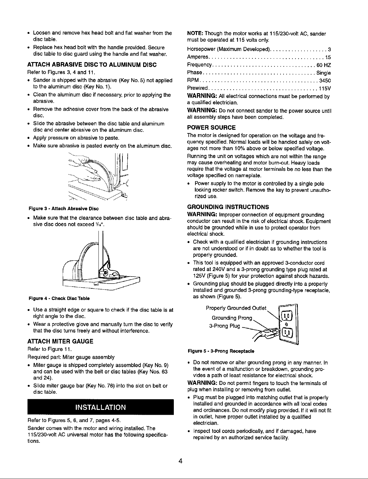
Refer to Figures 2 and 11.
Required parts and hardware:
• Belt table with trunnion
• Handle
• 8mm Flat washer
• Positionbelt table (Key No. 63) on the belt housing (Key
No. 48) so that the trunnion (Key No. 18) trave(s on the
slide (Key No. 20).
• Set the belt table position so that the 0° mark on the trun-
nion is aligned with the pointer (Key No. 54).
• Secure belt table position usingthe handle and flatwasher
(Key Hoe. 10 and 16). Tighten handle into the threaded hole
on the belt housing.
]elt Tension Handle
,_1.-Table Look Handle
Figure2 - AttachBeltTable
• Sander is shipped with the belt tension handle (Key No. 52)
at the released position. Pull down the handle toward the
belt table totension the belt.
• Make sure that the clearance between the belt and belt
table does not exceed _/1,".
• Wear protective glove and manually push the belt to verify
that belt travels smoothlyand without interference.
POSITION DISC TABLE
Refer to Figure 11.
Required part: Handle
• Sander isshipped with the disctable (Key No.24) attached
to the disc guard (Key No. 11) usinga handle withflat
washer one side and a hex head boltwith flat washer on the
other side.
I
H
3
• Loosen and remove hex head bolt and flat washer from the
disc table.
• Replace hex head bolt with the handle provided. Secure
disc table to disc guard using the handle and flat washer.
ATTACH ABRASIVE DISCTO ALUMINUM DISC
Refer to Figures 3, 4 and 11.
• Sander is shipped with the abrasive (Key No. 5) not applied
to the aluminum disc (Key No. 1).
• Clean the aluminum disc if necessary, priorto applyingthe
abrasive.
• Remove the adhesive cover from the back of the abrasive
disc.
• Slide the abrasive between the disc table and aluminum
disc and center abrasive on the aluminum disc.
• Apply pressure on abrasive to paste.
• Make sure abrasive is pasted evenly on the aluminum disc.
NOTE: Though the motor works at 115/230-volt AC, sander
must be operated at 115 voltsonly.
Horsepower (Maximum Developed)................... 3
Amperes ...................................... 15
Frequency.................................. 60 HZ
Phase ..................................... Single
RPM ....................................... 3450
Prewired.................................... 115V
WARNING: All electricalconnections must be performed by
a qualifiedelectrician.
WARNING: Do not connect sander to the power source until
all assembly steps have been completed.
POWER SOURCE
The motor is designed for operation on the voltage and fre-
quency specified. Normal loads will be handled safely on volt-
ages not more than 10% above or below specified voltage.
Running the unit on voltages which are not within the range
may cause overheating and motor burn-out. Heavy loads
require that the voltage at motor terminals be no less than the
voltage specified on nameplate.
• Power supply to the motor is controlled by a single pole
locking rocker switch. Remove the key to prevent unautho-
rized use.
Figure3 - AttachAbrasive Disc
• Make sure that the clearance between disc table and abra-
sive disc does not exceed '/_".
Figure 4 - Check DlscTable
• Use a straight edge or square to check if the disc table is at
right angle to the disc.
• Wear a protective glove and manually turn the disc to verify
that the disc turns freely and without interference.
ATTACH MITER GAUGE
Refer to Figure 11.
Required part: Miter gauge assembly
• Miter gauge is shipped completely assembled (Key No. 9)
and can be used with the belt or disc tables (Key Nos. 63
and 24).
• Slide miter gauge bar (Key No. 76) into the slot on belt or
disc table.
Refer to Figures 5, 6, and 7, pages 4-5.
Sander comes with the motor and wiring installed. The
115/230-volt AC universal motor has the following specifica-
tions.
GROUNDING INSTRUCTIONS
WARNING: Improper connection of equipment grounding
conductor can result in the risk of electrical shock. Equipment
should be grounded while in use to protect operator from
electricalshock.
• Check with a qualified electrician ifgrounding instructions
are not understood or if in doubt as to whether the tool is
properly grounded.
• This tool is equipped with an approved 3-conductor cord
rated at 240V and a 3-prong grounding type plug rated at
125V (Figure 5) for your protection against shock hazards.
• Grounding plug should be plugged directly into a properly
Lnstailedand grounded 3-preng grounding-type receptacle,
as shown (Figure 5).
Properly Grounded Outlet ---_,_
Grounding Prong
3-Prong Plug __
Figure 5 - 3.Prong Receptacle
• Do not remove or alter groundingprong in any manner. In
the event of a malfunction or breakdown, grounding pro-
vides a path of least resistance for electrical shock.
WARNING: Do not permLt fingers to touch the terminals of
plug when installing or removing from outlet.
• Plug must be plugged into matching outlet that is properly
installed and grounded in accordance with all local codes
and ordinances. Do not modify plug provided. If it will not fit
in outlet, have proper outlet installed by a qualified
electrician.
• Inspect tool cords periodically, and if damaged, have
repaired by an authorized service facility.
• Green(orgreenandyellow)conductorincordisthe
groundingwire.Ifrepairorreplacementoftheelectriccord
orplugisnecessary,donotconnectthegreen(orgreen
andyellow)wiretoaliveterminal.
• Where a 2-prong wall receptacle is encountered, it must be
replaced with a properly grounded 3-prong receptacle
installed in accordance with National Electric Code and
local codes and ordinances.
WARNING: This work should be performed by a qualified
electrician.
A temporary 3-prong to 2-prong grounding adapter (see
Figure 6) is available for connecting plugs to a two pole outlet
if it is properly grounded.
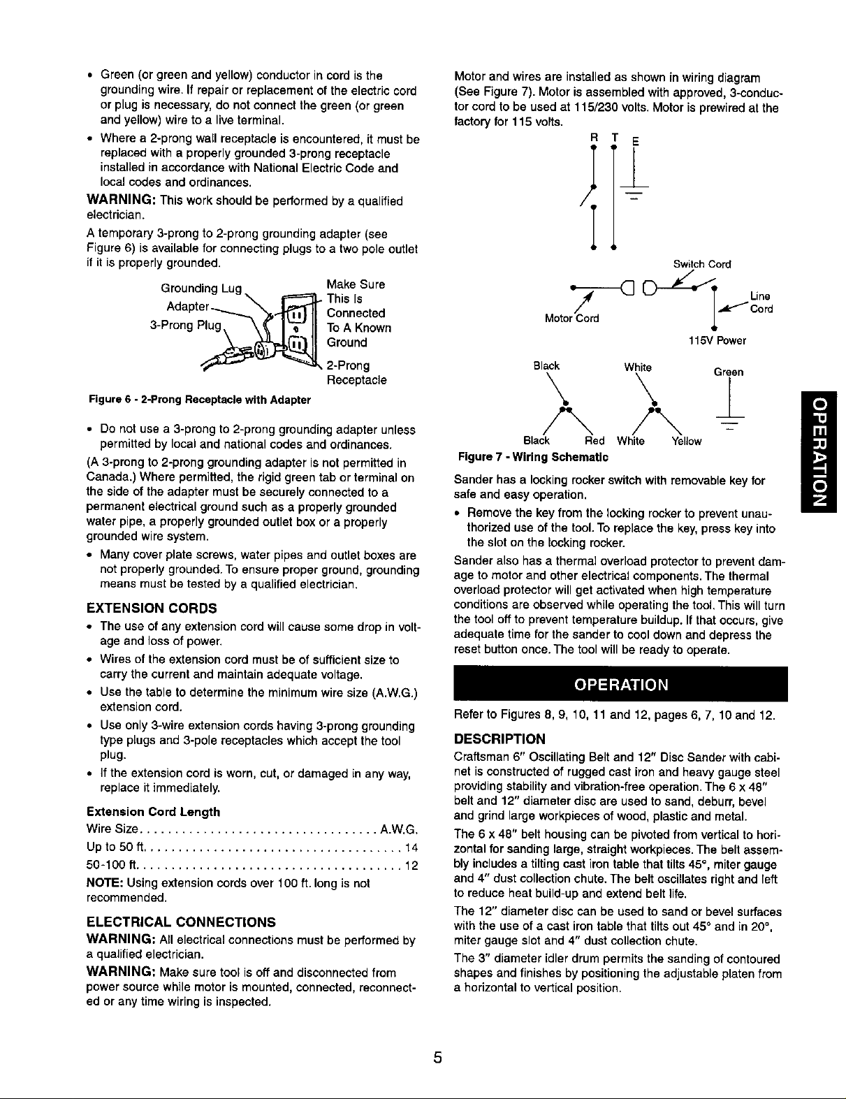
Motor and wires are installed as shown in wiring diagram
(See Figure 7). Motor is assembled with approved, 3-conduc-
torcord to be used at 115/230 volts.Motor is prewired at the
factoryfor 115 volts.
R E
Switch Cord
Grounding Lug Make Sure
Th,s,sAdapter Connected
3-Prong Plug_ _ I"_-" II To A Known
Ground
2-Prong
Receptacle
Figure 6 - 2-Prong Receptacle with Adapter
• Do not use a 3-prong to 2-prong grounding adapter unless
permitted by local and national codes and ordinances.
(A 3-prong to 2-prong grounding adapter is not permitted in
Canada.) Where permitted, the rigid green tab or terminal on
the side of the adapter must be securely connected to a
permanent electrical ground such as a properly grounded
water pipe, a properly grounded outlet box or a properly
grounded wire system.
• Many cover plate screws, water pipes and outlet boxes are
not properly grounded. To ensure proper ground, grounding
means must be tested by a qualified electrician.
EXTENSION CORDS
• The use of any extension cord will cause some drop in volt-
age and loss of power.
• Wires of the extension cord must be of sufficient size to
carry the current and maintain adequate voltage.
• Use the table to determine the minimum wire size (A.W.G.)
extension cord.
• Use only 3-wire extension cords having 3-prong grounding
type plugs and 3-pole receptacles which accept the tool
plug.
• Ifthe extension cord is worn, cut, or damaged in any way,
replace it immediately.
Extension Cord Length
Wire Size .................................. A.W,G.
Upto50 ft ..................................... 14
50 -100 ft...................................... 12
NOTE: Using extension cords over 100 ft. long is not
recommended.
ELECTRICAL CONNECTIONS
WARNING: All electrical connections must be performed by
a qualified electrician.
WARNING: Make sure tool is off and disconnected from
power source while motor is mounted, connected, reconnect-
ed or any time wiring is inspected.
_ Line
Motor Cord
Black White
\ \
Black Red
Figure 7-Wiring SchemaUc
Sander has a locking rocker switch with removable key for
safe and easy operation.
• Remove the key from the locking rockerto preventunau-
thorized use of the tool.To replace the key, press key into
the slot on the lockingrocker.
Sander also has a thermal overload protectorto prevent dam-
age to motor and other electrical components. The thermal
overload protector willget activated when high temperature
conditionsare observed while operating the tool, This willturn
the tool offto prevent temperature buildup. Ifthat occurs, give
adequate time for the sander to cool down and depress the
reset button once. The toolwill be ready to operate.
Refer to Figures 8, 9, 10, 11 and 12, pages 6, 7, 10 and 12.
White Yellow
_L.....'/Cord
115V Power
Green
I
DESCRIPTION
Craftsman 6" Oscillating Belt and 12" Disc Sander with cabi-
net is constructed of rugged cast iron and heavy gauge steel
providing stability and vibration-free operation. The 6 x 48"
belt and 12" diameter disc are used to sand, deburr, bevel
and grind large workpieces of wood, plastic and metal.
The 6 x 48" belt housing can be pivoted from vertical to hori-
zontal for sanding large, straight workpieces. The belt assem-
bly includes a tilting cast iron table that tilts 45°, miter gauge
and 4" dust collection chute. The belt oscillates right and left
to reduce heat build-up and extend belt life.
The 12" diameter disc can be used to sand or bevel surfaces
with the use of a cast irontable that tilts out 45° and in 20°,
miter gauge slot and 4" dust collection chute.
The 3" diameter idler drum permits the sanding of contoured
shapes and finishes by positioning the adjustable platen from
a horizontal to vertical position.
5
 Loading...